EP1548757A1 - Method of automatically marking article and automatic marking device - Google Patents
Method of automatically marking article and automatic marking device Download PDFInfo
- Publication number
- EP1548757A1 EP1548757A1 EP03784539A EP03784539A EP1548757A1 EP 1548757 A1 EP1548757 A1 EP 1548757A1 EP 03784539 A EP03784539 A EP 03784539A EP 03784539 A EP03784539 A EP 03784539A EP 1548757 A1 EP1548757 A1 EP 1548757A1
- Authority
- EP
- European Patent Office
- Prior art keywords
- wire
- article
- spouting
- coloring agent
- automatically marking
- Prior art date
- Legal status (The legal status is an assumption and is not a legal conclusion. Google has not performed a legal analysis and makes no representation as to the accuracy of the status listed.)
- Granted
Links
Images


Classifications
-
- H—ELECTRICITY
- H01—ELECTRIC ELEMENTS
- H01B—CABLES; CONDUCTORS; INSULATORS; SELECTION OF MATERIALS FOR THEIR CONDUCTIVE, INSULATING OR DIELECTRIC PROPERTIES
- H01B7/00—Insulated conductors or cables characterised by their form
- H01B7/36—Insulated conductors or cables characterised by their form with distinguishing or length marks
- H01B7/361—Insulated conductors or cables characterised by their form with distinguishing or length marks being the colour of the insulation or conductor
-
- H—ELECTRICITY
- H01—ELECTRIC ELEMENTS
- H01B—CABLES; CONDUCTORS; INSULATORS; SELECTION OF MATERIALS FOR THEIR CONDUCTIVE, INSULATING OR DIELECTRIC PROPERTIES
- H01B13/00—Apparatus or processes specially adapted for manufacturing conductors or cables
- H01B13/34—Apparatus or processes specially adapted for manufacturing conductors or cables for marking conductors or cables
- H01B13/345—Apparatus or processes specially adapted for manufacturing conductors or cables for marking conductors or cables by spraying, ejecting or dispensing marking fluid
Definitions
- the present invention relates to a method and device for automatically marking an article such as an electric wire including an electrically conductive core wire and an insulating coating which coats the core wire.
- a motor vehicle is provided with a wiring harness for supplying an electric power from an electric source to electronic equipment and for transferring control signals and so on from a computer to electronic equipment.
- the wiring harness includes a plurality of electric wires 106 (shown in Fig. 14) as articles, electric connectors, each being attached to an end of the wire 106, and so on.
- the wire 106 includes an electrically conductive core wire 105 (shown in Fig. 14) and a coating made of insulating synthetic resin, which coats the core wire 105.
- the wire 106 is so-called a coated wire.
- the wire 106 has been produced by using a producing device 100 shown in Fig. 14, which includes a supply unit 101, extrusion-coating unit 102, cooling water bath 103 and winding unit 104.
- the producing device 100 Upon producing the wire 106, the producing device 100 transfers a core wire 105 or a wire 106 in turn through the supply unit 101, extrusion-coating unit 102, cooling water bath 103 and winding unit 104.
- the device 100 has a plurality of pulleys 107 to transfer the core wire 105 or wire 106.
- the supply unit 101 supplies the core wire 105 which has no coating thereon.
- the extrusion-coating unit 102 extrudes the insulating synthetic resin onto the circumference of the core wire 105 supplied from the supply unit 101, forming the coating.
- the cooling water bath 103 cools the coating.
- the winding unit 104 cuts the wire 106 into a specific length and winds the cut wire 106 around a dram or the like placing the wire 106 in a condition of being shipped.
- the producing device 100 produces the wire 106.
- a connector includes an electrically conductive terminal fitting and an insulating connector housing.
- the terminal fitting is attached to an end of the wire 106 and electrically connected to the core wire 105 of the wire 106.
- the connector housing is formed into a box-shape and receives the terminal fitting.
- the wire 106 Upon assembling a wiring harness, first the wire 106 is cut into a specific length and thereafter a terminal fitting is attached to an end of the wire 106. The wires 106 are connected to each other according to the need. Thereafter, the terminal fitting is inserted into the connector housing, thereby assembling the wiring harness.
- the size of the core wire 105, the material of the coating (for possible change in the material depending on heat-resisting property), and a purpose of use must be distinguished.
- the purpose of use means a control signal for an airbag, antilock brake system and vehicle speed information, and a vehicle system in which the wire 106 in a power transmission system is used.
- an outer surface of the wire 106 of the wiring harness is formed in a stripe pattern with two different colors.
- a coloring agent is added into the synthetic resin which constitutes the coating.
- the synthetic resin is mixed with the coloring agent so as to make the color of the synthetic resin be the same as that of the coloring agent.
- the synthetic resin having the same color as that of the coloring agent is extrusion-coated onto the circumference of the core wire 105.
- a part of the outer surface of the wire 106 is colored with a color different from the color of the coloring agent, thereby coloring the wire 106 into a stripe pattern.
- a maker of motor vehicles receives various demands from users. That is, a motor vehicle is forced to have various electronic equipment therein. Accordingly, the wiring harness needs many types of the wire 106, such as a hundred of types of the wire 106. In this case, the wires 106 having various colors are needed. Therefore, the producing device 100 must frequently change the color of the coating of the wire 106.
- the extrusion-coating unit 102 upon changing the color of the coating (that is, the color of the wire 106), the extrusion-coating unit 102 is halted once and then, the coloring agent to be mixed with the synthetic resin is changed. In this case, when the wires 106 having various colors are produced, the extrusion-coating unit 102 must be halted frequently, causing the deterioration in the production efficiency of the wire 106.
- the coloring agent to be added to the synthetic resin is changed with the extrusion-coating unit 102 being kept in operation.
- the synthetic resin is mixed with both the coloring agent before the change and the coloring agent after the change, resulting in that the color of the coating becomes a mixed color of the color of the coloring agent before the change and that of the coloring agent after the change.
- the wire 106 having such a mixed color cannot be used for making a wiring harness because the mixed color is not a desired color to be used in the system described above.
- the resulted wire 106 has inevitably a portion which cannot be used to make a wiring harness, causing the deterioration in the yield of the material of the wire 106. Further, a part of the outer surface cannot be easily changed to a color which is different from the color of the coloring agent.
- the present invention described in claim 1 is a method of automatically marking an article which is transferred in one direction, comprising the steps of:
- a plurality of the coloring agents of the respective specific amount are spouted toward the outer surface of the article so as to mark the outer surface. Since the coloring agents of the respective specific amount are spouted, therefore when one coloring agent is replaced by the other coloring agent, the coloring agent is prevented from being mixed with the other coloring agent and the coloring agent to be adhered on the article can be changed immediately.
- the transfer speed of the article is detected and a plurality of the coloring agents are spouted toward the outer surface of the article in response to the detected transfer speed.
- a time interval for spouting the coloring agent is shortened, while the transfer speed of the article decreases, then a time interval for spouting the coloring agent is elongated, thereby the distance between the coloring agents adhered on the outer surface of the article can be maintained constant even when the transfer speed of the article changes. Consequently, even when the transfer speed of the article changes, the coloring agents can be adhered on the outer surface of the article according to a predetermined pattern.
- the coloring agent means a liquid substance, in which a coloring material (organic substance for use in industry) is dissolved and dispersed in water or other solvent.
- a coloring material organic substance for use in industry
- the organic substance described above is a dye or a pigment (mainly, organic substance and synthetic product). Sometimes, a dye is used as a pigment and a pigment is used as a dye.
- the coloring agent is a coloring liquid or coating material.
- the coloring liquid is a liquid, in which a dye is dissolved or dispersed in a solvent.
- the coating material is a material, in which a pigment is dispersed in a liquid dispersion.
- the dye permeates into the coating.
- the pigment adheres to the outer surface without permeating into the coating of the wire.
- "to mark the outer surface of the coating” means to dye a part of the outer surface of the coating with a dye or to coat a part of the outer surface of the coating with a pigment.
- the solvent and liquid dispersion have an affinity to the synthetic resin for constituting the coating in order to securely permeate the dye into the coating of the wire or to make the pigment securely adhere to the outer surface of the coating of the wire.
- the present invention described in claim 2 is the method of automatically marking an article according to claim 1, wherein the article is an electric wire.
- the outer surface of an electric wire as the article is marked. Since the marking is carried out in response to the transfer speed of the wire, the coloring agents can be adhered on the outer surface of the wire according to a predetermined pattern even when the transfer speed of the wire changes. Of course, the wire being transferred with a high speed can be securely marked and the wire of long length can be marked.
- the present invention described in claim 3 is a device for automatically marking an article which is transferred in one direction, comprising:
- a plurality of the spouting means spout the respective specific amount of the coloring agents toward the outer surface of the article so as to mark the outer surface.
- a plurality of the spouting means spout the coloring agent of the respective different colors. Since the respective specific amount of the coloring agents are spouted, when one coloring agent to be adhered on the article is replaced by the other coloring agent, one coloring agent is prevented from being mixed with the other coloring agent and the coloring agent to be adhered on the article can be changed immediately.
- the detecting means detects the transfer speed of the article and the control means controls the spouting of a plurality of the coloring agents toward the outer surface of the article in response to the detected transfer speed.
- the transfer speed of the article increases, then a time interval for spouting the coloring agent is shortened, while the transfer speed of the article decreases, then a time interval for spouting the coloring agent is elongated, thereby the distance between the coloring agents adhered on the outer surface of the article can be maintained constant even when the transfer speed of the article changes. Consequently, even when the transfer speed of the article changes, the coloring agents can be adhered on the outer surface of the article according to a predetermined pattern stored in the storing means.
- the present invention described in claim 4 is the device for automatically marking an article according to claim 3, wherein a plurality of the spouting means are arranged along the transfer direction of the article and the control means makes the spouting means spout the coloring agent according to a distance between the spouting means.
- a plurality of the spouting means are arranged along the transfer direction of the article. Therefore, the outer surface of the article can be securely marked with a plurality of the coloring agents.
- the storing means stores a distance between the spouting means and the control means controls the spouting means to spout the coloring agent according to the distance between the spouting means. Accordingly, the coloring agents can be adhered on the outer surface of the article according to a predetermined pattern stored in the storing means.
- the present invention described in claim 5 is the device for automatically marking an article according to claim 3, wherein a plurality of the spouting means are arranged along a circumferential direction around the article.
- a plurality of the spouting means are arranged along a circumferential direction around the article. Therefore, the outer surface of the article can be securely marked with a plurality of the coloring agents. Since a plurality of the spouting means are arranged along a circumferential direction around the article, the device for automatically marking an article can be made compact.
- a distance between means for transferring the article and the spouting means along the transferring direction of the article, that is, for example, the length direction of the electric wire can be shortened. Therefore, the article can be prevented from shaking in the vicinity of the spouting means, thereby the spouting means can securely mark the outer surface of the article.
- the present invention described in claim 6 is the device for automatically marking an article according to claim 5, wherein the spouting means spouts the coloring agent through an opening, which faces the outer surface of the article, a straight line obtained by connecting a center of the opening and a center of the article runs along a spouting direction of the coloring agent, and the spouting direction crosses both perpendicular and horizontal directions at an angle of 45°.
- the spouting means spouts the coloring agent through an opening, which faces the outer surface of the article, a straight line obtained by connecting a center of the opening and a center of the article runs along a spouting direction of the coloring agent, and the spouting direction crosses both perpendicular and horizontal directions at an angle of 45°. Therefore, even when the article shakes both in the perpendicular and horizontal directions, the spouting means can securely mark the outer surface of the article.
- the present invention described in claim 7 is the device for automatically marking an article as claimed in any one of claims 3 - 6, further comprising a device body for receiving the storing means and the control means, wherein the device body comprises a plurality of connectors for connecting the device body to the spouting means and the connectors are provided in the same number as that of the spouting means according to the respective spouting means.
- the device comprises a device body for receiving the storing means and the control means, wherein the device body comprises a plurality of connectors for connecting the device body to the spouting means and the connectors are provided in the same number as that of the spouting means according to the respective spouting means. Therefore, with one device body, a plurality of the spouting means can be securely controlled and a space for installing the device can be reduced.
- the present invention described in claim 8 is the device for automatically marking an article as claimed in any one of claims 3 - 7, wherein the article is an electric wire.
- the outer surface of an electric wire as the article is marked. Since the marking is carried out in response to the transfer speed of the wire, the coloring agents can be adhered on the outer surface of the wire according to a predetermined pattern even when the transfer speed of the wire changes. Of course, the wire being transferred with a high speed can be securely marked and the wire of long length can be marked.
- the present invention described in claim 9 is the device for automatically marking an article according to claim 8, wherein the electric wire is put in an electric wire cutting machine which cuts the electric wire after transferring the electric wire in said one direction.
- the electric wire is put in an electric wire cutting machine which cuts the electric wire after transferring the electric wire in said one direction. Therefore, when a long electric wire is cut into a specific length, the wire can be marked with a specific pattern. A space for installing can be reduced and a man-hour for processing the wire can be reduced.
- a device for automatically marking an electric wire (hereinafter, a device for automatically marking) as a device for automatically marking an article according to a first preferred embodiment of the present invention will be explained with reference to Figs. 1 - 7.
- the device 1 for automatically marking is mounted on an electric wire cutting machine 2, which cuts the wire 3 into a specific length, and the device 1 forms a mark 9 on a part of the outer surface 3a of the wire 3. That is, the device 1 for automatically marking marks the outer surface 3a of the wire 3 as the article.
- the electric wire cutting machine 2 includes a frame 10 as a machine body, guide roll 11, delivery roll 12 as a transfer means, corrective unit 13 as means for providing tension, slack-absorbing unit 14 as means for absorbing a slack, duct 16, and cutting mechanism 18 as means for processing.
- the frame 10 is placed on a floor in a plant.
- the frame 10 extends in a horizontal direction.
- the guide roll 11 is rotatably attached to an end of the frame 10.
- the guide roll 11 winds up a long electric wire 3 on which a mark 9 is not formed.
- the guide roll 11 delivers the wire 3 in sequence to the corrective unit 13, slack-absorbing unit 14, spouting unit 311, 312, duct 16, encoder 33 and cutting mechanism 18.
- a pair of the delivery rolls 12 are provided at an opposite end of the frame 10.
- the pair of the delivery rolls 12 is rotatably supported by the frame 10 and is arranged along the vertical direction.
- the delivery roll 12 is rotated in a direction reverse to that for the mating delivery roll 12 with the same revolving speed as that of the mating delivery roll 12 by a motor (not shown in the figure).
- the pair of the delivery rolls 12 puts the wire 3 therebetween and pulls the wire 3 from the guide roll 11 in the longitudinal direction of the wire 3.
- the delivery roll 12 functions as means for pulling the wire 3 in the longitudinal direction of the wire 3 so as to transfer the wire 3.
- the delivery rolls 12 transfer the wire 3 in the longitudinal direction of the wire 3 so that the wire 3 is moved in the longitudinal direction of the wire 3 relatively to a coloring nozzle 351, 352 (explained later on) of the spouting unit 311, 312. That is, the wire 3 is transferred from the guide roll 11 toward the delivery roll 12 along an arrow K shown in Fig. 1.
- the arrow K indicates the transfer direction of the wire 3.
- the corrective unit 13 is provided at the delivery roll 12-side of the guide roll 11, that is, between the guide roll 11 and delivery roll 12. That is, the corrective unit 13 is provided at the downstream side of the guide roll 11 in the transfer direction K of the wire 3 and provided at the upstream side of the delivery roll 12 in the transfer direction K of the wire 3.
- the corrective unit 13 includes a plate-shaped unit body 20, a plurality of first rollers 21, and a plurality of second rollers 22.
- the unit body 20 is fixed to the frame 10.
- the first and second rollers 21, 22 are rotatably supported by the unit body 20.
- a plurality of the first rollers 21 are arranged along the horizontal direction (i.e. the transfer direction K) above the wire 3.
- a plurality of the second rollers 22 are arranged along the horizontal direction (i.e. the transfer direction K) below the wire 3.
- the first and second rollers 21, 22 are provided zigzag as shown in Fig. 1.
- the corrective unit 13 puts the wire 3, which is delivered from the guide roll 11 by the delivery roll 12, between the first and second rollers 21, 22.
- the corrective unit 13 makes the wire 3 straight.
- the corrective unit 13 gives friction force to the wire 3 by putting the wire 3 between the first and second rollers 21, 22. That is, the corrective unit 13 gives the wire 3 the friction force, which is a first bias force H1 acting in a direction reverse to the direction (i.e. the transfer direction K) in which the delivery roll 12 pulls the wire 3.
- the first bias force H1 is smaller than a force that the delivery roll 12 pulls the wire 3. Therefore, the corrective unit 13 gives the tension acting along the longitudinal direction of the wire 3 to the wire 3 so as to stretch the wire 3.
- the slack-absorbing unit 14 is provided at the delivery roll 12-side of the corrective unit 13, that is, provided between the corrective unit 13 and the delivery roll 12. That is, the slack-absorbing unit 14 is provided at the downstream side of the corrective unit 13 along the transfer direction K of the wire 3 and provided at the upstream side of the delivery roll 12 along the transfer direction K of the wire 3. The slack-absorbing unit 14 is provided between the corrective unit 13 and the spouting units 311, 312.
- the slack-absorbing unit 14 includes frames 23 for supporting a pair of guide rollers, the pair of the guide rollers 24, a frame 25 for supporting a transfer roller, the transfer roller 26, and air cylinder 27 as bias means.
- the frames 23 are fixed to the frame 10.
- the frames 23 are provided above the frame 10.
- the frames 23 are arranged in the transfer direction K of the wire 3 having a distance therebetween.
- the pair of the guide rollers 24 is rotatably supported by the frame 23.
- the guide roller 24 is placed below the wire 3 and guides the wire 3 so that the wire 3 does not come off from the transfer direction K by coming in contact with the wire 3 on the outer surface of the guide roller 24. That is, the guide roller 24 guides the wire 3 along the transfer direction K.
- the frame 25 is fixed to the frame 10.
- the frame 25 rises upward from the frame 10.
- the frame 25 is provided between the pair of the frames 23.
- the transfer roller 26 is rotatably supported by the frame 25 and supported movably in the vertical direction.
- the transfer roller 26 is placed above the wire 3.
- the transfer roller 26 is supported movably in the vertical direction, so that the transfer roller 26 is supported movably in a direction crossing the transfer direction K of the wire 3 at right angles.
- the transfer roller 26 is provided at the center between the rollers 24.
- the air cylinder 27 includes a cylinder body 28 and a stretch rod 29 stretchable from the body 28.
- the cylinder body 28 is fixed to the frame 25 and placed above the wire 3.
- the stretch rod 29 extends downward from the body 28. That is, the stretch rod 29 extends toward the wire 3 from the body 28.
- the transfer roller 26 is attached to the stretch rod 29.
- the air cylinder 27 biases the stretch rod 29, that is, biases the transfer roller 26 downward along the direction crossing the transfer direction K at right angles with a second bias force H2 (shown in Figs. 1 and 2). That is, the air cylinder 27 biases the transfer roller 26 toward the wire 3 with the second bias force H2.
- the second bias force H2 is smaller than the first bias force H1.
- the wire 3 advances along arrow K by inertia and the wire 3 slackens between the pair of the guide rollers 24.
- the stretch rod 29 of the air cylinder 27 extends and the transfer roller 26 is displaced, for example, to a position indicated by an alternate long and two short dashes line shown in Fig. 2.
- the slack-absorbing unit 14 biases the wire 3, which slackens between the guide rollers 24, along the direction crossing the transfer direction K at right angles so as to absorb the slack, thereby keeping the wire 3 stretching.
- the duct 16 is provided at the delivery roll 12-side of the spouting units 311, 312 (explained later on) of the device 1 for automatically marking and provided between the spouting units 311, 312 and the delivery roll 12. That is, the duct 16 is provided at the downstream side of the spouting units 311, 312 along the transfer direction of the wire 3.
- the duct 16 is formed cylindrical and guides the wire 3 therethrough.
- the duct 16 is connected to suction means (not shown in the figure) such as a vacuum pump. The suction means sucks gas in the duct 16 so as to prevent solvent or fluid dispersion in the coloring agent from leaking out from the device 1.
- the cutting mechanism 18 is arranged at the downstream side of a pair of rotors 42 of the encoder 33 (explained later on) of the device 1 along the transfer direction K of the wire 3.
- the cutting mechanism 18 includes a pair of cutting blades 30a and 30b, which is arranged in the vertical direction.
- the pair of cutting blades 30a and 30b puts the wire 3, which is delivered by the pair of the delivery rolls 12, therebetween and cuts the wire 3.
- the pair of cutting blades 30a and 30b parts away from each other of course the pair of cutting blades 30a and 30b parts away from the wire 3.
- the electric wire cutting machine 2 puts the wire 2 between the delivery rolls 12, in a state that the pair of cutting blades 30a and 30b parts away from each other, and delivers the wire 3 along arrow K. After delivering the wire 3 of a specific length, the delivery roll 12 is halted. Then, the pair of cutting blades 30a and 30b approaches each other, puts the wire 3 therebetween, and cuts the wire 3. Thus, the electric wire cutting machine 2 transfers the wire 3 as an article along arrow K.
- the wires 3 constitute a wiring harness, which is arranged in, for example, a motor vehicle as a mobile unit.
- the wire 3 includes an electrically conductive core wire 4 and an electrically insulating coating 5.
- the core wire 4 is formed by twisting a plurality of element wires 6 made of conductive metal.
- the core wire 4 may be constructed by one element wire 6.
- the coating 6 is made of synthetic resin such as polyvinyl chloride (PVC).
- PVC polyvinyl chloride
- the coating 5 coats the core wire 4. Therefore, the outer surface 3a of the wire 3 is the outer surface of the coating 5.
- the coating is monochrome P.
- the outer surface 3a of the wire 3 may be monochrome P by mixing a desired coloring agent into the synthetic resin of the coating 5.
- the monochrome P may be a color of the synthetic resin itself without mixing a coloring agent into the synthetic resin of the coating 5.
- the outer surface 3a of the wire 3, that is, the outer surface of the coating 5 is called non-colored. That is, the "non-colored" means that the outer surface 3a of the wire 3 has a color of the synthetic resin itself.
- a mark 9 consisting of a plurality of first spots 7 and a plurality of second spots 8 is formed.
- the first spot 7 has a first color B (shown by parallel diagonal lines in Figs. 6 and 7).
- the first color B is different from the monochrome P.
- the second spot 8 has a second color R (shown by other parallel diagonal lines in Figs. 6 and 7).
- the second color R is different from both the monochrome P and the first color B.
- the first and second spots 7, 8 are round in a plan view.
- a plurality of the spots 7 and a plurality of the spots 8 are arranged in the longitudinal direction of the wire 3 according to a predetermined pattern.
- first spots 7 are formed, then four second spots 8 are formed and then, six first spots 7 are further formed.
- the following three distances are predetermined: a distance D1 between the centers of the first spots 7 adjacent to each other in the longitudinal direction of the wire 3; a distance D2 between the centers of the second spots 8 adjacent to each other in the longitudinal direction of the wire 3; and a distance D3 between the center of the first spot 7 and the center of the second spot 8 adjacent to each other in the longitudinal direction of the wire 3.
- a plurality of the wire 3 constructed as described above are twisted and, for example, a connector is attached thereto, thereby constructing the wiring harness.
- the connector is coupled with a mating connector of various electronic equipment in a motor vehicle, thereby the wiring harness, i.e. the wires 3 transfer various signals or electric power to the various electronic equipment.
- the wire 3 is the article described in the claims and this specification.
- the wire 3 can be distinguished from the other wire 3.
- the colors B and R are used to distinguish the type of the wire 3 of the wiring harness and to distinguish a system in a vehicle, that is, to distinguish a purpose of the wire 3 of the wiring harness.
- the device 1 for automatically marking forms the mark 9 on the outer surface 3a of the wire 3.
- the device 1 includes the first spouting unit 311 as the spouting means, the second spouting unit 312 as the spouting means, encoder 33 as the detecting means, and control device 34.
- the first and second spouting units 311 and 312 are arranged along arrow K.
- the spouting units 311, 312 are provided at the delivery roll 12-side of the slack-absorbing unit 14 of the wire cutting machine 2 and provided between the slack-absorbing unit 14 and the delivery roll 12. That is, the spouting units 311, 312 are provided at the downstream side of the slack-absorbing unit 14 along the transfer direction of the wire 3 and provided at the upstream side of the delivery roll 12 along the transfer direction of the wire 3. That is, the spouting units 311, 312 are provided between the delivery roll 12 and the corrective unit 13.
- the first spouting unit 311 includes a first nozzle 351 and a first valve 361.
- the first nozzle 351 faces the wire 3, which is transferred along arrow K by the pair of the delivery rolls 12.
- the first nozzle 351 includes a hole 351a, through which the first coloring agent can pass.
- the hole 351a extends straightly toward the outer surface 3a of the wire 3.
- An opening 351b of the hole 351a faces the wire 3, which is transferred along arrow K by the delivery rolls 12.
- the first spouting unit 311 includes the opening 351b which faces the wire 3.
- the opening 351b can guide the first coloring agent therethrough.
- the first coloring agent is supplied into the hole 351a of the first nozzle 351 from a first coloring agent-supply source 37 (shown in Fig. 2).
- the first coloring agent has the first color B.
- the first coloring agent-supply source 37 is connected to the first nozzle 351.
- the first valve 361 is provided between the first nozzle 351 and the first coloring agent-supply source 37 and connected to them. Further, a pressurized gas-supply source 38 (shown in Fig. 2) is connected to the first coloring agent-supply source 37. The pressurized gas-supply source 38 supplies pressurized gas into the first coloring agent-supply source 37. Further, pressurized gas-supply source 38 supplies pressurized gas into a second coloring agent-supply source 41 (explained later on).
- the first coloring agent within the hole 351a of the first nozzle 351 spouts toward the outer surface 3a of the wire 3 passing through the opening 351b.
- the first spouting unit 311 spouts the first coloring agent through the opening 351b, which faces the outer surface 3a of the wire 3.
- the first spouting unit 311 spouts the first coloring agent along arrow K1 shown in Fig. 4, which is parallel to the longitudinal direction of the hole 351a.
- the arrow K1 indicates the spouting direction described in the claims and this specification.
- valve 361 When the valve 361 is closed, the spouting of the first coloring agent within the first nozzle 351 is halted. In response to a signal from a valve-driving circuit 46 (explained later on) of the control device 34, the first valve 361 is opened for a predetermined period of time, thereby the first spouting unit 311 spouts a specific amount of the first coloring agent toward the outer surface 3a of the wire 3.
- the second spouting unit 312 is provided at the upstream side of the first spouting unit 311 along the transfer direction K of the wire 3.
- the second spouting unit 312 includes a second nozzle 352 and a second valve 362.
- the second nozzle 352 faces the wire 3, which is transferred along arrow K by the pair of the delivery rolls 12.
- the second nozzle 352 includes a hole 352a, through which the second coloring agent can pass.
- the hole 352a extends straightly toward the outer surface 3a of the wire 3.
- An opening 352b of the hole 352a faces the wire 3, which is transferred along arrow K by the delivery rolls 12.
- the second spouting unit 312 includes the opening 352b which faces the wire 3.
- the opening 352b can guide the second coloring agent therethrough.
- the second coloring agent is supplied into the hole 352a of the second nozzle 352 from a second coloring agent-supply source 41 (shown in Fig. 2).
- the second coloring agent has the second color R.
- the second coloring agent-supply source 41 is connected to the second nozzle 352.
- the second valve 362 is provided between the second nozzle 352 and the second coloring agent-supply source 41 and connected to them. Further, the pressurized gas-supply source 38 is connected to the second coloring agent-supply source 41.
- the second valve 362 is opened, with the aid of the pressurized gas supplied from the pressurized gas-supply source 38, the second coloring agent within the hole 352a of the second nozzle 352 spouts toward the outer surface 3a of the wire 3 passing through the opening 352b.
- the second spouting unit 312 spouts the second coloring agent through the opening 352b, which faces the outer surface 3a of the wire 3.
- the second spouting unit 312 spouts the second coloring agent along arrow K2 shown in Fig. 5, which is parallel to the longitudinal direction of the hole 352a.
- the arrow K2 indicates the spouting direction described in the claims and this specification.
- the valve 362 When the valve 362 is closed, the spouting of the second coloring agent within the second nozzle 352 is halted. In response to a signal from the valve-driving circuit 46 of the control device 34, the second valve 362 is opened for a predetermined period of time, thereby the second spouting unit 312 spouts a specific amount of the second coloring agent toward the outer surface 3a of the wire 3. Thus, the first and second spouting units 311 and 312 spout the specific amount of the respective coloring agents as a drop.
- the first and second coloring agents described above correspond to the coloring agents described in the claims and this specification, and mean liquid substances, in which the coloring material (organic substance for use in industry) is dissolved and dispersed in water or other solvent.
- the organic substance described above is a dye or a pigment (mainly, organic substance and synthetic product). Sometimes, a dye is used as a pigment and a pigment is used as a dye.
- the coloring agent is a coloring liquid or coating material.
- the coloring liquid is a liquid, in which a dye is dissolved or dispersed in a solvent.
- the coating material is a material, in which a pigment is dispersed in a liquid dispersion.
- the first and second spouting units 311 and 312 dyes a part of the outer surface 3a of the wire 3 with a dye, or alternatively, give a part of the outer surface 3a of the wire 3 of a coat of a pigment. That is, marking the outer surface 3a of the wire 3 means dyeing a part of the outer surface 3a of the wire 3 with a dye, or alternatively, giving a part of the outer surface 3a of the wire 3 of a coat of a pigment.
- the solvent and liquid dispersion have an affinity to the synthetic resin for constituting the coating 5 in order to securely permeate the dye into the coating 5 or to make the pigment securely adhere to the outer surface 3a.
- spouting the coloring agent as a drop means that the liquid coloring agent in its state of a drop is ejected toward the outer surface 3a of the wire 3 with the aid of bias. That is, the nozzles 351, 352 of the device 1 for automatically marking according to the preferred embodiment ejects the coloring agent in its state of a drop toward the outer surface 3a of the wire 3 with the aid of bias.
- the encoder 33 includes a pair of rotors 42.
- the rotors 42 are provided at the downstream side of the delivery roll 12 along the transfer direction K of the wire 3.
- the rotor 42 is rotatable around the axis.
- the outer circumferential surface of the rotor 42 comes in contact with the outer surface 3a of the wire 3, which is put between the delivery rolls 12.
- the pair of the rotors 42 puts the wire 3 therebetween.
- the core wire 4 moves, that is, the wire 3 moves along arrow K
- the rotor 42 rotates.
- the transfer distance of the core wire 4, that is, the transfer distance of the wire 3 along arrow K has a linear relation with the revolving number of the rotor 42.
- the encoder 33 is connected to a pulse count circuit 44 (explained later on) of the control device 34.
- the encoder 33 When the rotor 42 rotates by an every specific angle, the encoder 33 outputs a pulse signal to the control device 34. That is, the encoder 33 outputs an information in response to the transfer speed of the wire 3 transferring along arrow K to the pulse count circuit 44.
- encoder 33 measures an information in response to the transfer speed of the wire 3 and outputs the information in response to the transfer speed of the wire 3 to the pulse count circuit 44.
- the encoder 33 outputs a pulse signal in response to the transfer distance of the wire 3 with friction between the wire 3 and the rotor 42.
- the information of the speed may be obtained at another position and the information obtained may be fed back so as to carry out a specific comparative computation.
- the control device 34 includes a box-shaped device body 43, the pulse count circuit 44, valve-selecting circuit 45, a plurality of valve-driving circuits 46, and a plurality of interfaces (shown by I/F in Fig. 3; hereinafter I/F) 47 as connectors.
- the device body 43 receives the pulse count circuit 44, valve-selecting circuit 45, and a plurality of the valve-driving circuits 46.
- the pulse count circuit 44 counts the number of the pulse signals inputted from the encoder 33.
- the pulse count circuit 44 is connected to the valve-selecting circuit 45 and outputs an information indicating which number of the pulse signal is inputted at that time to the valve-selecting circuit 45.
- the pulse signal generated in the encoder of very high frequency may be divided so as to input it to the pulse count circuit 44.
- the valve-selecting circuit 45 is connected to the valve-driving circuits 46.
- the valve-selecting circuit 45 outputs a signal for opening the respective valves 361, 362 to the valve-driving circuits 46.
- the valve-selecting circuit 45 outputs a signal for opening the respective valves 361, 362 to the valve-driving circuits 46 according to a pattern of the mark 9 to be formed on the outer surface 3a of the wire 3 such as the distances D1, D2 and D3 and a distance L (shown in Fig. 2) between the centers C1 and C2 of the respective openings 351b and 352b.
- the distance L is a distance between the spouting means.
- valve-selecting circuit 45 memorizes which is to be opened the first valve 361 or second valve 362, or alternatively, both of which to be kept closed, and controls respective valve-driving circuits 46 according to this memorized pattern.
- the pulse count circuit 44 is directly connected to the valve-driving circuit 46, the valve-selecting circuit 45 can be passed.
- the valve-selecting circuit 45 memorizes in advance a pattern for marking the outer surface 3a of the wire 3.
- the valve-driving circuit 46 makes the respective spouting units 311, 312 spout the specific amount of the first or second coloring agent toward the outer surface 3a of the wire 3 in accordance with the memorized pattern in response to the transfer speed of the wire 3 inputted from the encoder 33.
- the valve-selecting circuit 45 makes the respective spouting units 311, 312 spout the first or second coloring agent according to the distance L between the centers C1 and C2 of the openings 351b and 352b, respectively.
- the valve-selecting circuit 45 corresponds to both the storing means and control means.
- the pulse count circuit 44 or the valve-selecting circuit 45 consists of a known digital circuit or the like.
- the valve-driving circuit 46 and I/F 47 are provided in the same number as the spouting units 311 or 312, corresponding to the respective spouting units 311 and 312. Valves 361 and 362 of the respective spouting units 311 and 312 are connected to the valve-driving circuit 46 through the I/F 47.
- the valve-driving circuit 46 When a signal for opening the valve 361, 362 is inputted from the valve-selecting circuit 45, the valve-driving circuit 46 outputs the signal to the valve 361, 362 through I/F 47 and so on.
- the valve-driving circuit 46 outputs the signal for opening the valve 361, 362 to the valve 361, 362, then the valve 361, 362 is opened.
- valve-driving circuit 46 outputs the signal described above to the corresponding valves 361, 362 so as to control the opening/closing motion of the corresponding valves 361, 362.
- the I/F 47 is used for electrically connecting the valve-driving circuit 46 to the corresponding valves 361, 362.
- the I/F 47 is attached to, for example, an outer wall of the device body 43.
- the guide roll 11 is mounted on the frame 10.
- the pair of the cutting blades 30a and 30b is kept apart from each other and the wire 3 wound around the guide roll 11 is passed in turn through the corrective unit 13, slack-absorbing unit 14, spouting units 311, 312 and duct 16, and put between the pair of the delivery rolls 12.
- the nozzles 351, 352 of the spouting units 311, 312 are mounted on specific positions and the coloring agent-supply sources 37, 41 are connected to the respective nozzles 351, 352.
- the pressurized gas-supply source 38 is connected to the coloring agent-supply sources 37, 41 and gas within the duct 16 is sucked by suck means.
- the delivery rolls 12 is rotated, the wire 3 is pulled from the guide roll 11 so as to transfer the wire 3 along the longitudinal direction of the wire 3, and the corrective unit 13 gives the friction force of the first bias force H1 to the wire 3 so as to stretch the wire 3.
- the air cylinder 27 gives the second bias force H2 to the transfer roll 26, that is, to the wire 3.
- the valve-driving circuit 46 that is connected to the first valve 361 opens the first valve 361 six times for a specific period of time according to the distance D1 described above. Then, as shown in Fig. 4, the first spouting unit 311 spouts (ejects) the specific amount of the first coloring agent toward the outer surface 3a of the wire 3.
- the solvent or liquid dispersion evaporates from the coloring agent adhered on the outer surface 3a of the wire 3 so as to dyes the outer surface 3a of the wire 3 with the dye, or alternatively, coats the pigment on the outer surface 3a.
- the solvent or liquid dispersion evaporated from the coloring agent adhered on the outer surface 3a of the wire 3 is sucked by the suck means from the duct 16.
- the outer surface 3a of the wire 3 is colored.
- the valve-driving circuit 46 that is connected to the second valve 362 opens the second valve 362 four times for a specific period of time according to the distance D2 described above. Then, as shown in Fig. 5, the second spouting unit 312 spouts (ejects) the specific amount of the second coloring agent toward the outer surface 3a of the wire 3.
- the valve-driving circuit 46 that is connected to the first valve 361 opens again the first valve 361 six times for a specific period of time according to the distance D1 described above. Then, the first spouting unit 311 spouts (ejects) the specific amount of the first coloring agent toward the outer surface 3a of the wire 3.
- the control device 34 judges that the wire 3 of the specific length is delivered on the basis of the information from the encoder and so on, the control device 34 halts the motion of the delivery roll 12. Then, the wire 3 slackens between the pair of the guide rollers 24 of the slack-absorbing unit 14 and the transfer roller 26 biased by the second bias force H2 shifts to a position indicated by an alternate long and two short dashes line shown in Fig. 1. Then, the stretch rod 29 of the air cylinder 27 of the slack-absorbing unit 14 extends. Then, the slack-absorbing unit 14 absorbs the slack of the wire 3.
- the respective specific amount of the first and second coloring agents are spouted (ejected) toward the outer surface 3a of the wire 3, thereby marking the outer surface 3a. Since the respective specific amount of the first and second coloring agents are spouted (ejected), upon changing the coloring agent to be adhered on the outer surface 3a of the wire 3, these coloring agents are prevented from being mixed with each other and the coloring agent can be changed immediately. Accordingly, the production yield of the wire 3 can be prevented from deteriorating and the color of the mark 9 to be formed on the wire 3 can be changed easily.
- the encoder 33 detects the transfer speed of the wire 3 and the control device 34 controls the spouting of a plurality of the coloring agents toward the outer surface 3a of the wire 3 according to the transfer speed.
- the pulse count circuit 44 counts the pulse signals sent from the encoder 33 and the valve-selecting circuit 45 opens or closes the respective valves 361, 362 according to the turn of the pulse signals.
- the distances between the coloring agents adhered on the outer surface 3a of the wire 3, that is, the distances D1, D2 and D3 can be maintained constant. That is, even if the transfer speed of the wire 3 changes, the coloring agents can be adhered on the outer surface 3a of the wire 3 according to a predetermined pattern. That is, the outer surface 3a of the wire 3 can be marked according to a predetermined pattern.
- the first and second spouting units 311 and 312 are arranged along arrow K. Therefore, the outer surface 3a of the wire 3 can be securely marked with the first and second coloring agents.
- the valve-selecting circuit 45 memorizes the distance L described above and the valves 361, 362 are controlled according to the distance L. Therefore, the outer surface 3a of the wire 3 can be marked according to a predetermined pattern.
- the I/F 47 for connecting to the spouting units 311 or 312 are provided in the same number as the spouting units 311 or 312 in the device body 43 of the control device 34. Therefore, only one device body 43, that is, only one control device 34 can securely control the first and second spouting units 311 and 312, thereby reducing a necessary space for installing.
- the device 1 for automatically marking is mounted on the wire cutting machine 2. Therefore, when the wire having long length is to be cut into a specific length, the wire 3 can be marked with a specific pattern. Therefore, the man-hour required to process the wire 3 can be restricted.
- a device 1 for automatically marking an electric wire hereinafter, a device for automatically marking
- a device for automatically marking as a device for automatically marking an article according to a second preferred embodiment of the present invention will be explained with reference to Figs. 8 - 10.
- the device 1 for automatically marking according to the second preferred embodiment forms a mark 9 on the outer surface 3a of the wire 3. That is, the device 1 marks the outer surface 3a of the wire 3.
- the first spot 7 shifts relatively from the second spot 8 in the circumferential direction of the wire 3.
- the first and second spouting units 311 and 312 are arranged in the circumferential direction of the wire 3 that is transferred along arrow K.
- a straight line L1 (shown by an alternate long and two short dashes line in Fig. 8) obtained by connecting the center C1 of an opening 351b of a hole 351a of the first nozzle 351 of the first spouting unit 311 with the center C of the wire 3 is parallel to arrow K1.
- a control device 34 opens or closes the respective valves 361 and 362 on the basis of a signal sent from an encoder 33. Then, the device 1 marks the outer surface 3a of the wire 3 according to a predetermined pattern.
- the delivery rolls 12 of the wire cutting machine 2 deliver the wire 3 for a specific length, the delivery rolls 12 are halted.
- Cutting blades 30a, 30b of a cutting mechanism 18 cuts the wire 3, on the surface 3a of which the mark 9 is formed.
- the wire 3 shown in Figs. 9 and 10, on the surface 3a of which the mark 9 is formed, is produced.
- the respective specific amount of the first and second coloring agents are spouted, upon changing the coloring agent to be adhered on the outer surface 3a of the wire 3, these coloring agents are prevented from being mixed with each other and the coloring agent can be changed immediately. Accordingly, the production yield of the wire 3 can be prevented from deteriorating and the color of the mark 9 to be formed on the wire 3 can be changed easily.
- the encoder 33 detects the transfer speed of the wire 3 and the control device 34 controls the spouting of a plurality of the coloring agents toward the outer surface 3a of the wire 3 according to the transfer speed. Therefore, even if the transfer speed of the wire 3 changes, the distances between the coloring agents adhered on the outer surface 3a of the wire 3, that is, the distances D1, D2 and D3 can be maintained constant. That is, even if the transfer speed of the wire 3 changes, the coloring agents can be adhered on the outer surface 3a of the wire 3 according to a predetermined pattern. That is, the outer surface 3a of the wire 3 can be marked according to a predetermined pattern.
- the I/F 47 for connecting to the spouting units 311 or 312 are provided in the same number as the spouting units 311 or 312 in the device body 43 of the control device 34. Therefore, only one device body 43, that is, only one control device 34 can securely control the first and second spouting units 311 and 312, thereby reducing a necessary space for installing.
- the device 1 for automatically marking is mounted on the wire cutting machine 2. Therefore, when the wire having long length is to be cut into a specific length, the wire 3 can be marked with a specific pattern. Therefore, the man-hour required to process the wire 3 can be restricted.
- the device 1 for automatically marking can be made compact.
- the wire 3 can be prevented from shaking in the vicinity of the spouting units 311, 312 and the spouting units 311, 312 can securely mark the outer surface 3a of the wire 3.
- the device 1 for automatically marking includes two spouting units 311 and 312.
- the device 1 may include three or more spouting units 311, 312, 313, ---, 31N as the spouting means.
- the device 1 includes N spouting units 311, 312, 313, ---, 31N (N:integer) and the device body 43 of the control device 34 includes N I/F 47.
- These spouting units 311, 312, 313, ---, 31N have the respective nozzles 351, 352, 353, ---, 35N and the respective valves 361, 362, 363, ---, 36N.
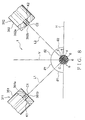
- the spouting units 311, 312, 313, and 314 as the spouting means may be arranged in the circumferential direction around the wire 3.
- the respective spouting units 311, 312, 313, and 314 are attached to a ring-shaped member 48 around the wire 3.
- the respective spouting units 311, 312, 313, and 314 are arranged in the circumferential direction around the wire 3 having the same distance therebetween.
- respective straight lines obtained by connecting the centers of the openings of the holes of the respective nozzles 351, 352, 353 and 354 of the respective spouting units 311, 312, 313, and 314 and the center of the wire 3 is parallel to the respective spouting direction of the respective coloring agents. Furthermore, each straight line crosses both the vertical direction and the horizontal direction at an angle of 45°.
- the device 1 includes respective valves 361, 362, 363 and 364 for the respective nozzles 351, 352, 353 and 354.
- the device 1 includes four spouting units 311, 312, 313 and 314. However, instead, in the present invention, the device 1 may include two or more spouting units.
- the outer surface 3a of the wire 3 can be securely marked with a plurality of the coloring agents.
- the device 1 for automatically marking can be made compact and the outer surface 3a of the wire 3 can be securely marked.
- control device 34 is constructed by digital circuits and so on.
- control device 34 may be constructed by a computer including a known RAM, ROM, CPU and known nonvolatile storage such as EPROM.
- nonvolatile storage such as the EPROM is the storing means and the CPU is the control means.
- the outer surface 3a of the wire 3 as the article is marked as an example.
- the device 1 for automatically marking may mark not only the electric wire 3 but also an outer surface of various articles being transferred by, for example, a known belt conveyer and the like.
- the article may be, for example, a connector housing, grommet, protector and various circuit components.
- the article means a matter, onto which the marking can be applied.
- the encoder 33 detects the transfer speed of an endless ring-shaped belt of the belt conveyer.
- the electric wire 3 for constituting a wiring harness to be mounted on a motor vehicle.
- the wire 3 may be used not only for a motor vehicle but also for various electronic equipment such as a portable computer and various electric machines.
- acrylic-based coating material ink (dye-based or pigment-based) and ultraviolet ink (UV ink) may be used as the coloring liquid or the coating material.
- ink ink-based or pigment-based
- UV ink ultraviolet ink
- a plurality of the coloring agents of the respective specific amount are spouted toward the outer surface of the article so as to mark the outer surface. Since the coloring agents of the respective specific amount are spouted, therefore when one coloring agent is replaced by the other coloring agent, the coloring agent is prevented from being mixed with the other coloring agent and the coloring agent to be adhered on the article can be changed immediately. Accordingly, the yield of the article can be prevented from deteriorating and the color for the mark to be formed on the article can be easily changed.
- the transfer speed of the article is detected and a plurality of the coloring agents are spouted toward the outer surface of the article in response to the detected transfer speed. Therefore, even when the transfer speed of the article changes, the distance between the coloring agents adhered on the outer surface of the article can be maintained constant. That is, the outer surface of the article can be marked according to a predetermined pattern.
- the outer surface of an electric wire as the article is marked. Since the marking is carried out in response to the transfer speed of the wire, the outer surface of the wire can be marked according to a predetermined pattern even when the transfer speed of the wire changes. Of course, the wire being transferred with a high speed can be securely marked and the wire having long length can be marked. Accordingly, the production yield of the electric wire can be prevented from deteriorating and the color for the mark to be formed on the wire can be easily changed.
- a plurality of the spouting means spout the respective specific amount of the coloring agents toward the outer surface of the article so as to mark the outer surface.
- a plurality of the spouting means spout the coloring agent of the respective different colors. Since the respective specific amount of the coloring agents are spouted, when one coloring agent to be adhered on the article is replaced by the other coloring agent, one coloring agent is prevented from being mixed with the other coloring agent and the coloring agent to be adhered on the article can be changed immediately. Accordingly, the yield of the article can be prevented from deteriorating and the color for the mark to be formed on the article can be easily changed.
- the detecting means detects the transfer speed of the article and the control means controls the spouting of a plurality of the coloring agents toward the outer surface of the article in response to the detected transfer speed. Therefore, even when the transfer speed of the article changes, the distance between the coloring agents adhered on the outer surface of the article can be maintained constant. Therefore, the outer surface of the article can be marked according to a predetermined pattern.
- a plurality of the spouting means are arranged along the transfer direction of the article. Therefore, the outer surface of the article can be securely marked with a plurality of the coloring agents.
- the storing means stores a distance between the spouting means and the control means controls the spouting means to spout the coloring agent according to the distance between the spouting means. Therefore, the outer surface of the article can be marked according to a predetermined pattern.
- a plurality of the spouting means are arranged along a circumferential direction around the article. Therefore, the outer surface of the article can be securely marked with a plurality of the coloring agents. Since a plurality of the spouting means are arranged along a circumferential direction around the article, the device for automatically marking an article can be made compact.
- a distance between means for transferring the article and the spouting means along the transferring direction of the article, that is, for example, the length direction of the electric wire can be shortened. Therefore, the article can be prevented from shaking in the vicinity of the spouting means, thereby the spouting means can securely mark the outer surface of the article.
- the spouting means spouts the coloring agent through an opening, which faces the outer surface of the article, a straight line obtained by connecting a center of the opening and a center of the article runs along a spouting direction of the coloring agent, and the spouting direction crosses both perpendicular and horizontal directions at an angle of 45°. Therefore, even when the article shakes both in the perpendicular and horizontal directions, the spouting means can securely mark the outer surface of the article.
- the device comprises a device body for receiving the storing means and the control means, wherein the device body comprises a plurality of connectors for connecting the device body to the spouting means and the connectors are provided in the same number as that of the spouting means according to the respective spouting means. Therefore, with one device body, a plurality of the spouting means can be securely controlled and a space for installing the device can be reduced.
- the outer surface of an electric wire as the article is marked. Since the marking is carried out in response to the transfer speed of the wire, the coloring agents can be adhered on the outer surface of the wire according to a predetermined pattern even when the transfer speed of the wire changes. Of course, the wire being transferred with a high speed can be securely marked and the wire of long length can be marked.
- the electric wire is put in an electric wire cutting machine which cuts the electric wire after transferring the electric wire in said one direction. Therefore, when a long electric wire is cut into a specific length, the wire can be marked with a specific pattern. A space for installing can be reduced and a man-hour for processing the wire can be reduced.
Abstract
Description
- The present invention relates to a method and device for automatically marking an article such as an electric wire including an electrically conductive core wire and an insulating coating which coats the core wire.
- Various electronic equipment is mounted on a motor vehicle as a mobile unit. Therefore, a motor vehicle is provided with a wiring harness for supplying an electric power from an electric source to electronic equipment and for transferring control signals and so on from a computer to electronic equipment. The wiring harness includes a plurality of electric wires 106 (shown in Fig. 14) as articles, electric connectors, each being attached to an end of the
wire 106, and so on. - The
wire 106 includes an electrically conductive core wire 105 (shown in Fig. 14) and a coating made of insulating synthetic resin, which coats thecore wire 105. Thewire 106 is so-called a coated wire. Thewire 106 has been produced by using a producingdevice 100 shown in Fig. 14, which includes asupply unit 101, extrusion-coating unit 102,cooling water bath 103 andwinding unit 104. - Upon producing the
wire 106, the producingdevice 100 transfers acore wire 105 or awire 106 in turn through thesupply unit 101, extrusion-coating unit 102,cooling water bath 103 andwinding unit 104. Thedevice 100 has a plurality ofpulleys 107 to transfer thecore wire 105 orwire 106. - The
supply unit 101 supplies thecore wire 105 which has no coating thereon. The extrusion-coating unit 102 extrudes the insulating synthetic resin onto the circumference of thecore wire 105 supplied from thesupply unit 101, forming the coating. The cooling water bath 103 cools the coating. Thewinding unit 104 cuts thewire 106 into a specific length and winds thecut wire 106 around a dram or the like placing thewire 106 in a condition of being shipped. Thus, the producingdevice 100 produces thewire 106. - A connector includes an electrically conductive terminal fitting and an insulating connector housing. The terminal fitting is attached to an end of the
wire 106 and electrically connected to thecore wire 105 of thewire 106. The connector housing is formed into a box-shape and receives the terminal fitting. - Upon assembling a wiring harness, first the
wire 106 is cut into a specific length and thereafter a terminal fitting is attached to an end of thewire 106. Thewires 106 are connected to each other according to the need. Thereafter, the terminal fitting is inserted into the connector housing, thereby assembling the wiring harness. - As for the
wire 106 of the wiring harness, the size of thecore wire 105, the material of the coating (for possible change in the material depending on heat-resisting property), and a purpose of use must be distinguished. Here, the purpose of use means a control signal for an airbag, antilock brake system and vehicle speed information, and a vehicle system in which thewire 106 in a power transmission system is used. - So far, in order to distinguish the purpose of use as described above, an outer surface of the
wire 106 of the wiring harness is formed in a stripe pattern with two different colors. In a conventional producingdevice 100 as shown in Fig. 14, in an extrusion-coating unit 102, a coloring agent is added into the synthetic resin which constitutes the coating. Then, in the extrusion-coating unit 102, the synthetic resin is mixed with the coloring agent so as to make the color of the synthetic resin be the same as that of the coloring agent. Then, the synthetic resin having the same color as that of the coloring agent is extrusion-coated onto the circumference of thecore wire 105. Further, a part of the outer surface of thewire 106 is colored with a color different from the color of the coloring agent, thereby coloring thewire 106 into a stripe pattern. - A maker of motor vehicles receives various demands from users. That is, a motor vehicle is forced to have various electronic equipment therein. Accordingly, the wiring harness needs many types of the
wire 106, such as a hundred of types of thewire 106. In this case, thewires 106 having various colors are needed. Therefore, the producingdevice 100 must frequently change the color of the coating of thewire 106. - In the conventional producing
device 100 as shown in Fig. 14, upon changing the color of the coating (that is, the color of the wire 106), the extrusion-coating unit 102 is halted once and then, the coloring agent to be mixed with the synthetic resin is changed. In this case, when thewires 106 having various colors are produced, the extrusion-coating unit 102 must be halted frequently, causing the deterioration in the production efficiency of thewire 106. - Therefore, a method has been proposed, in which the coloring agent to be added to the synthetic resin is changed with the extrusion-
coating unit 102 being kept in operation. When the coloring agent is changed with the extrusion-coating unit 102 being kept in operation, immediately after changing the coloring agent, the synthetic resin is mixed with both the coloring agent before the change and the coloring agent after the change, resulting in that the color of the coating becomes a mixed color of the color of the coloring agent before the change and that of the coloring agent after the change. Thewire 106 having such a mixed color cannot be used for making a wiring harness because the mixed color is not a desired color to be used in the system described above. That is, when the coloring agent is changed with the extrusion-coating unit 102 being kept in operation, theresulted wire 106 has inevitably a portion which cannot be used to make a wiring harness, causing the deterioration in the yield of the material of thewire 106. Further, a part of the outer surface cannot be easily changed to a color which is different from the color of the coloring agent. - Thus, with the conventional producing device, it has been difficult to change a color of a mark, which is formed on the outer surface of the wire, without deteriorating the production efficiency of the wire as an article.
- It is therefore an objective of the present invention to provide a method and device for automatically marking an article, by which the deterioration in the yield can be prevented from occurring and a color of a mark to be formed on the article can be easily changed.
- In order to attain the above objective, the present invention described in
claim 1 is a method of automatically marking an article which is transferred in one direction, comprising the steps of: - storing in advance a pattern for coloring an outer surface of the article with a plurality of coloring agents of respective colors different from each other;
- detecting a transfer speed of the article; and
- spouting a plurality of the coloring agents of respective specific amount toward the outer surface of the article according to the pattern in response to the detected transfer speed.
-
- According to the invention described in
claim 1, a plurality of the coloring agents of the respective specific amount are spouted toward the outer surface of the article so as to mark the outer surface. Since the coloring agents of the respective specific amount are spouted, therefore when one coloring agent is replaced by the other coloring agent, the coloring agent is prevented from being mixed with the other coloring agent and the coloring agent to be adhered on the article can be changed immediately. - Further, the transfer speed of the article is detected and a plurality of the coloring agents are spouted toward the outer surface of the article in response to the detected transfer speed. When the transfer speed of the article increases, then a time interval for spouting the coloring agent is shortened, while the transfer speed of the article decreases, then a time interval for spouting the coloring agent is elongated, thereby the distance between the coloring agents adhered on the outer surface of the article can be maintained constant even when the transfer speed of the article changes. Consequently, even when the transfer speed of the article changes, the coloring agents can be adhered on the outer surface of the article according to a predetermined pattern.
- The coloring agent means a liquid substance, in which a coloring material (organic substance for use in industry) is dissolved and dispersed in water or other solvent. The organic substance described above is a dye or a pigment (mainly, organic substance and synthetic product). Sometimes, a dye is used as a pigment and a pigment is used as a dye. In this specification, as a substantial example, the coloring agent is a coloring liquid or coating material.
- The coloring liquid is a liquid, in which a dye is dissolved or dispersed in a solvent. The coating material is a material, in which a pigment is dispersed in a liquid dispersion. When the outer surface of the wire is colored with a coloring liquid, the dye permeates into the coating. When the outer surface of the wire is colored with a coating material, the pigment adheres to the outer surface without permeating into the coating of the wire. In the specification, "to mark the outer surface of the coating" means to dye a part of the outer surface of the coating with a dye or to coat a part of the outer surface of the coating with a pigment.
- Preferably, the solvent and liquid dispersion have an affinity to the synthetic resin for constituting the coating in order to securely permeate the dye into the coating of the wire or to make the pigment securely adhere to the outer surface of the coating of the wire.
- The present invention described in
claim 2 is the method of automatically marking an article according toclaim 1, wherein the article is an electric wire. - According to the invention described in
claim 2, the outer surface of an electric wire as the article is marked. Since the marking is carried out in response to the transfer speed of the wire, the coloring agents can be adhered on the outer surface of the wire according to a predetermined pattern even when the transfer speed of the wire changes. Of course, the wire being transferred with a high speed can be securely marked and the wire of long length can be marked. - The present invention described in
claim 3 is a device for automatically marking an article which is transferred in one direction, comprising: - storing means for storing a pattern for coloring an outer surface of the article with a plurality of coloring agents of respective colors different from each other;
- detecting means for detecting a transfer speed of the article;
- a plurality of spouting means for spouting the coloring agents of respective colors different from each other of respective specific amount toward the outer surface of the article; and
- control means to make a plurality of the spouting means spout the coloring agent toward the outer surface of the article according to the pattern in response to the transfer speed of the article detected by the detecting means.
-
- According to the invention described in
claim 3, a plurality of the spouting means spout the respective specific amount of the coloring agents toward the outer surface of the article so as to mark the outer surface. A plurality of the spouting means spout the coloring agent of the respective different colors. Since the respective specific amount of the coloring agents are spouted, when one coloring agent to be adhered on the article is replaced by the other coloring agent, one coloring agent is prevented from being mixed with the other coloring agent and the coloring agent to be adhered on the article can be changed immediately. - Further, the detecting means detects the transfer speed of the article and the control means controls the spouting of a plurality of the coloring agents toward the outer surface of the article in response to the detected transfer speed. When the transfer speed of the article increases, then a time interval for spouting the coloring agent is shortened, while the transfer speed of the article decreases, then a time interval for spouting the coloring agent is elongated, thereby the distance between the coloring agents adhered on the outer surface of the article can be maintained constant even when the transfer speed of the article changes. Consequently, even when the transfer speed of the article changes, the coloring agents can be adhered on the outer surface of the article according to a predetermined pattern stored in the storing means.
- The present invention described in
claim 4 is the device for automatically marking an article according toclaim 3, wherein a plurality of the spouting means are arranged along the transfer direction of the article and the control means makes the spouting means spout the coloring agent according to a distance between the spouting means. - According to the invention described in
claim 4, a plurality of the spouting means are arranged along the transfer direction of the article. Therefore, the outer surface of the article can be securely marked with a plurality of the coloring agents. Further, the storing means stores a distance between the spouting means and the control means controls the spouting means to spout the coloring agent according to the distance between the spouting means. Accordingly, the coloring agents can be adhered on the outer surface of the article according to a predetermined pattern stored in the storing means. - The present invention described in
claim 5 is the device for automatically marking an article according toclaim 3, wherein a plurality of the spouting means are arranged along a circumferential direction around the article. - According to the invention described in
claim 5, a plurality of the spouting means are arranged along a circumferential direction around the article. Therefore, the outer surface of the article can be securely marked with a plurality of the coloring agents. Since a plurality of the spouting means are arranged along a circumferential direction around the article, the device for automatically marking an article can be made compact. - Further, since a plurality of the spouting means are arranged along a circumferential direction around the article, a distance between means for transferring the article and the spouting means along the transferring direction of the article, that is, for example, the length direction of the electric wire can be shortened. Therefore, the article can be prevented from shaking in the vicinity of the spouting means, thereby the spouting means can securely mark the outer surface of the article.
- The present invention described in
claim 6 is the device for automatically marking an article according toclaim 5, wherein the spouting means spouts the coloring agent through an opening, which faces the outer surface of the article, a straight line obtained by connecting a center of the opening and a center of the article runs along a spouting direction of the coloring agent, and the spouting direction crosses both perpendicular and horizontal directions at an angle of 45°. - According to the invention described in
claim 6, the spouting means spouts the coloring agent through an opening, which faces the outer surface of the article, a straight line obtained by connecting a center of the opening and a center of the article runs along a spouting direction of the coloring agent, and the spouting direction crosses both perpendicular and horizontal directions at an angle of 45°. Therefore, even when the article shakes both in the perpendicular and horizontal directions, the spouting means can securely mark the outer surface of the article. - The present invention described in
claim 7 is the device for automatically marking an article as claimed in any one of claims 3 - 6, further comprising a device body for receiving the storing means and the control means, wherein the device body comprises a plurality of connectors for connecting the device body to the spouting means and the connectors are provided in the same number as that of the spouting means according to the respective spouting means. - According to the invention described in
claim 7, the device comprises a device body for receiving the storing means and the control means, wherein the device body comprises a plurality of connectors for connecting the device body to the spouting means and the connectors are provided in the same number as that of the spouting means according to the respective spouting means. Therefore, with one device body, a plurality of the spouting means can be securely controlled and a space for installing the device can be reduced. - The present invention described in
claim 8 is the device for automatically marking an article as claimed in any one of claims 3 - 7, wherein the article is an electric wire. - According to the invention described in
claim 8, the outer surface of an electric wire as the article is marked. Since the marking is carried out in response to the transfer speed of the wire, the coloring agents can be adhered on the outer surface of the wire according to a predetermined pattern even when the transfer speed of the wire changes. Of course, the wire being transferred with a high speed can be securely marked and the wire of long length can be marked. - The present invention described in
claim 9 is the device for automatically marking an article according toclaim 8, wherein the electric wire is put in an electric wire cutting machine which cuts the electric wire after transferring the electric wire in said one direction. - According to the invention described in
claim 9, the electric wire is put in an electric wire cutting machine which cuts the electric wire after transferring the electric wire in said one direction. Therefore, when a long electric wire is cut into a specific length, the wire can be marked with a specific pattern. A space for installing can be reduced and a man-hour for processing the wire can be reduced. -
- Figure 1 illustrates a construction of an electric wire cutting machine to which a device for automatically marking an article according to the first preferred embodiment of the present invention is mounted;
- Figure 2 illustrates a construction of the device for automatically marking an article shown in Fig. 1;
- Figure 3 illustrates mainly a construction of a control device of the device for automatically marking an article shown in Fig. 2;
- Figure 4 illustrates a state when the first spouting unit of the device for automatically marking an article shown in Fig. 2 is in operation;
- Figure 5 illustrates a state when the second spouting unit of the device for automatically marking an article shown in Fig. 2 is in operation;
- Figure 6 is a perspective view of an electric wire which is marked by the device for automatically marking an article shown in Fig. 2;
- Figure 7 is a plan view of the electric wire shown in Fig. 6;
- Figure 8 is a cross sectional view illustrating a construction of a primary part of a device for automatically marking an article according to the second preferred embodiment of the present invention;
- Figure 9 is a perspective view of an electric wire which is marked by the device for automatically marking an article shown in Fig. 8;
- Figure 10 is a plan view of the electric wire shown in Fig. 9;
- Figure 11 illustrates a construction of a primary part of a modified example of the device for automatically marking an article shown in Fig. 2;
- Figure 12 illustrates mainly a construction of a control device of the device for automatically marking an article shown in Fig. 11;
- Figure 13 is a perspective view illustrating a primary part of another modified example of the device for automatically marking an article shown in Fig. 2; and
- Figure 14 illustrates a construction of a conventional device for producing a colored electric wire.
-
- In the following, a device for automatically marking an electric wire (hereinafter, a device for automatically marking) as a device for automatically marking an article according to a first preferred embodiment of the present invention will be explained with reference to Figs. 1 - 7. As shown in Fig. 1, the
device 1 for automatically marking is mounted on an electricwire cutting machine 2, which cuts thewire 3 into a specific length, and thedevice 1 forms amark 9 on a part of theouter surface 3a of thewire 3. That is, thedevice 1 for automatically marking marks theouter surface 3a of thewire 3 as the article. - As shown in Fig. 1, the electric
wire cutting machine 2 includes aframe 10 as a machine body, guideroll 11,delivery roll 12 as a transfer means,corrective unit 13 as means for providing tension, slack-absorbingunit 14 as means for absorbing a slack,duct 16, and cuttingmechanism 18 as means for processing. - The
frame 10 is placed on a floor in a plant. Theframe 10 extends in a horizontal direction. Theguide roll 11 is rotatably attached to an end of theframe 10. Theguide roll 11 winds up a longelectric wire 3 on which amark 9 is not formed. Theguide roll 11 delivers thewire 3 in sequence to thecorrective unit 13, slack-absorbingunit 14, spoutingunit duct 16,encoder 33 andcutting mechanism 18. - A pair of the delivery rolls 12 are provided at an opposite end of the
frame 10. The pair of the delivery rolls 12 is rotatably supported by theframe 10 and is arranged along the vertical direction. Thedelivery roll 12 is rotated in a direction reverse to that for themating delivery roll 12 with the same revolving speed as that of themating delivery roll 12 by a motor (not shown in the figure). The pair of the delivery rolls 12 puts thewire 3 therebetween and pulls thewire 3 from theguide roll 11 in the longitudinal direction of thewire 3. - The delivery roll 12 functions as means for pulling the
wire 3 in the longitudinal direction of thewire 3 so as to transfer thewire 3. Thus, the delivery rolls 12 transfer thewire 3 in the longitudinal direction of thewire 3 so that thewire 3 is moved in the longitudinal direction of thewire 3 relatively to acoloring nozzle 351, 352 (explained later on) of thespouting unit wire 3 is transferred from theguide roll 11 toward thedelivery roll 12 along an arrow K shown in Fig. 1. The arrow K indicates the transfer direction of thewire 3. - The
corrective unit 13 is provided at the delivery roll 12-side of theguide roll 11, that is, between theguide roll 11 anddelivery roll 12. That is, thecorrective unit 13 is provided at the downstream side of theguide roll 11 in the transfer direction K of thewire 3 and provided at the upstream side of thedelivery roll 12 in the transfer direction K of thewire 3. Thecorrective unit 13 includes a plate-shapedunit body 20, a plurality offirst rollers 21, and a plurality ofsecond rollers 22. Theunit body 20 is fixed to theframe 10. - The first and
second rollers unit body 20. A plurality of thefirst rollers 21 are arranged along the horizontal direction (i.e. the transfer direction K) above thewire 3. A plurality of thesecond rollers 22 are arranged along the horizontal direction (i.e. the transfer direction K) below thewire 3. The first andsecond rollers - The
corrective unit 13 puts thewire 3, which is delivered from theguide roll 11 by thedelivery roll 12, between the first andsecond rollers corrective unit 13 makes thewire 3 straight. Thecorrective unit 13 gives friction force to thewire 3 by putting thewire 3 between the first andsecond rollers corrective unit 13 gives thewire 3 the friction force, which is a first bias force H1 acting in a direction reverse to the direction (i.e. the transfer direction K) in which thedelivery roll 12 pulls thewire 3. The first bias force H1 is smaller than a force that thedelivery roll 12 pulls thewire 3. Therefore, thecorrective unit 13 gives the tension acting along the longitudinal direction of thewire 3 to thewire 3 so as to stretch thewire 3. - The slack-absorbing
unit 14 is provided at the delivery roll 12-side of thecorrective unit 13, that is, provided between thecorrective unit 13 and thedelivery roll 12. That is, the slack-absorbingunit 14 is provided at the downstream side of thecorrective unit 13 along the transfer direction K of thewire 3 and provided at the upstream side of thedelivery roll 12 along the transfer direction K of thewire 3. The slack-absorbingunit 14 is provided between thecorrective unit 13 and the spoutingunits - As shown in Figs. 1 and 2, the slack-absorbing
unit 14 includesframes 23 for supporting a pair of guide rollers, the pair of theguide rollers 24, aframe 25 for supporting a transfer roller, thetransfer roller 26, andair cylinder 27 as bias means. Theframes 23 are fixed to theframe 10. Theframes 23 are provided above theframe 10. Theframes 23 are arranged in the transfer direction K of thewire 3 having a distance therebetween. - The pair of the
guide rollers 24 is rotatably supported by theframe 23. Theguide roller 24 is placed below thewire 3 and guides thewire 3 so that thewire 3 does not come off from the transfer direction K by coming in contact with thewire 3 on the outer surface of theguide roller 24. That is, theguide roller 24 guides thewire 3 along the transfer direction K. - The
frame 25 is fixed to theframe 10. Theframe 25 rises upward from theframe 10. Theframe 25 is provided between the pair of theframes 23. - The
transfer roller 26 is rotatably supported by theframe 25 and supported movably in the vertical direction. Thetransfer roller 26 is placed above thewire 3. Thetransfer roller 26 is supported movably in the vertical direction, so that thetransfer roller 26 is supported movably in a direction crossing the transfer direction K of thewire 3 at right angles. Thetransfer roller 26 is provided at the center between therollers 24. - The
air cylinder 27 includes acylinder body 28 and astretch rod 29 stretchable from thebody 28. Thecylinder body 28 is fixed to theframe 25 and placed above thewire 3. Thestretch rod 29 extends downward from thebody 28. That is, thestretch rod 29 extends toward thewire 3 from thebody 28. - The
transfer roller 26 is attached to thestretch rod 29. By receiving pressurized gas in thecylinder body 28, theair cylinder 27 biases thestretch rod 29, that is, biases thetransfer roller 26 downward along the direction crossing the transfer direction K at right angles with a second bias force H2 (shown in Figs. 1 and 2). That is, theair cylinder 27 biases thetransfer roller 26 toward thewire 3 with the second bias force H2. The second bias force H2 is smaller than the first bias force H1. - When a pair of
cutting blades cutting mechanism 18 approaches each other and thewire 3 is stopped to be cut, thewire 3 advances along arrow K by inertia and thewire 3 slackens between the pair of theguide rollers 24. At this time, in the slack-absorbingunit 14, since theair cylinder 27 biases thetransfer roller 26 with the second bias force H2, thestretch rod 29 of theair cylinder 27 extends and thetransfer roller 26 is displaced, for example, to a position indicated by an alternate long and two short dashes line shown in Fig. 2. Then, the slack-absorbingunit 14 biases thewire 3, which slackens between theguide rollers 24, along the direction crossing the transfer direction K at right angles so as to absorb the slack, thereby keeping thewire 3 stretching. - The
duct 16 is provided at the delivery roll 12-side of the spoutingunits 311, 312 (explained later on) of thedevice 1 for automatically marking and provided between the spoutingunits delivery roll 12. That is, theduct 16 is provided at the downstream side of the spoutingunits wire 3. Theduct 16 is formed cylindrical and guides thewire 3 therethrough. Theduct 16 is connected to suction means (not shown in the figure) such as a vacuum pump. The suction means sucks gas in theduct 16 so as to prevent solvent or fluid dispersion in the coloring agent from leaking out from thedevice 1. - The
cutting mechanism 18 is arranged at the downstream side of a pair ofrotors 42 of the encoder 33 (explained later on) of thedevice 1 along the transfer direction K of thewire 3. Thecutting mechanism 18 includes a pair ofcutting blades cutting blades cutting blades wire 3, which is delivered by the pair of the delivery rolls 12, therebetween and cuts thewire 3. When the pair ofcutting blades cutting blades wire 3. - The electric
wire cutting machine 2 puts thewire 2 between the delivery rolls 12, in a state that the pair ofcutting blades wire 3 along arrow K. After delivering thewire 3 of a specific length, thedelivery roll 12 is halted. Then, the pair ofcutting blades wire 3 therebetween, and cuts thewire 3. Thus, the electricwire cutting machine 2 transfers thewire 3 as an article along arrow K. - As shown in Fig. 6, the
device 1 for automatically marking marks theouter surface 3a of thewire 3. Thewires 3 constitute a wiring harness, which is arranged in, for example, a motor vehicle as a mobile unit. - The
wire 3 includes an electricallyconductive core wire 4 and an electrically insulatingcoating 5. Thecore wire 4 is formed by twisting a plurality ofelement wires 6 made of conductive metal. Thecore wire 4 may be constructed by oneelement wire 6. Thecoating 6 is made of synthetic resin such as polyvinyl chloride (PVC). Thecoating 5 coats thecore wire 4. Therefore, theouter surface 3a of thewire 3 is the outer surface of thecoating 5. - The coating is monochrome P. The
outer surface 3a of thewire 3 may be monochrome P by mixing a desired coloring agent into the synthetic resin of thecoating 5. Alternatively, the monochrome P may be a color of the synthetic resin itself without mixing a coloring agent into the synthetic resin of thecoating 5. In the latter case, theouter surface 3a of thewire 3, that is, the outer surface of thecoating 5 is called non-colored. That is, the "non-colored" means that theouter surface 3a of thewire 3 has a color of the synthetic resin itself. - On the
outer surface 3a of thewire 3, amark 9 consisting of a plurality offirst spots 7 and a plurality ofsecond spots 8 is formed. Thefirst spot 7 has a first color B (shown by parallel diagonal lines in Figs. 6 and 7). The first color B is different from the monochrome P. Thesecond spot 8 has a second color R (shown by other parallel diagonal lines in Figs. 6 and 7). The second color R is different from both the monochrome P and the first color B. - As shown in Fig. 7, the first and
second spots spots 7 and a plurality of thespots 8 are arranged in the longitudinal direction of thewire 3 according to a predetermined pattern. - In this example of the figure, six
first spots 7 are formed, then foursecond spots 8 are formed and then, sixfirst spots 7 are further formed. The following three distances are predetermined: a distance D1 between the centers of thefirst spots 7 adjacent to each other in the longitudinal direction of thewire 3; a distance D2 between the centers of thesecond spots 8 adjacent to each other in the longitudinal direction of thewire 3; and a distance D3 between the center of thefirst spot 7 and the center of thesecond spot 8 adjacent to each other in the longitudinal direction of thewire 3. - A plurality of the
wire 3 constructed as described above are twisted and, for example, a connector is attached thereto, thereby constructing the wiring harness. The connector is coupled with a mating connector of various electronic equipment in a motor vehicle, thereby the wiring harness, i.e. thewires 3 transfer various signals or electric power to the various electronic equipment. Thewire 3 is the article described in the claims and this specification. - By changing the colors B and R of the
respective spots mark 9, thewire 3 can be distinguished from theother wire 3. The colors B and R are used to distinguish the type of thewire 3 of the wiring harness and to distinguish a system in a vehicle, that is, to distinguish a purpose of thewire 3 of the wiring harness. - The
device 1 for automatically marking forms themark 9 on theouter surface 3a of thewire 3. As shown in Figs. 1 and 2, thedevice 1 includes thefirst spouting unit 311 as the spouting means, thesecond spouting unit 312 as the spouting means,encoder 33 as the detecting means, andcontrol device 34. The first andsecond spouting units - As shown in Fig. 1, the spouting
units unit 14 of thewire cutting machine 2 and provided between the slack-absorbingunit 14 and thedelivery roll 12. That is, the spoutingunits unit 14 along the transfer direction of thewire 3 and provided at the upstream side of thedelivery roll 12 along the transfer direction of thewire 3. That is, the spoutingunits delivery roll 12 and thecorrective unit 13. Thefirst spouting unit 311 includes afirst nozzle 351 and afirst valve 361. - The
first nozzle 351 faces thewire 3, which is transferred along arrow K by the pair of the delivery rolls 12. Thefirst nozzle 351 includes ahole 351a, through which the first coloring agent can pass. Thehole 351a extends straightly toward theouter surface 3a of thewire 3. Anopening 351b of thehole 351a faces thewire 3, which is transferred along arrow K by the delivery rolls 12. - The
first spouting unit 311 includes theopening 351b which faces thewire 3. Theopening 351b can guide the first coloring agent therethrough. The first coloring agent is supplied into thehole 351a of thefirst nozzle 351 from a first coloring agent-supply source 37 (shown in Fig. 2). The first coloring agent has the first color B. The first coloring agent-supply source 37 is connected to thefirst nozzle 351. - The
first valve 361 is provided between thefirst nozzle 351 and the first coloring agent-supply source 37 and connected to them. Further, a pressurized gas-supply source 38 (shown in Fig. 2) is connected to the first coloring agent-supply source 37. The pressurized gas-supply source 38 supplies pressurized gas into the first coloring agent-supply source 37. Further, pressurized gas-supply source 38 supplies pressurized gas into a second coloring agent-supply source 41 (explained later on). - When the
first valve 361 is opened, with the aid of the pressurized gas supplied from the pressurized gas-supply source 38, the first coloring agent within thehole 351a of thefirst nozzle 351 spouts toward theouter surface 3a of thewire 3 passing through theopening 351b. Thus, thefirst spouting unit 311 spouts the first coloring agent through theopening 351b, which faces theouter surface 3a of thewire 3. At this time, thefirst spouting unit 311 spouts the first coloring agent along arrow K1 shown in Fig. 4, which is parallel to the longitudinal direction of thehole 351a. The arrow K1 indicates the spouting direction described in the claims and this specification. - When the
valve 361 is closed, the spouting of the first coloring agent within thefirst nozzle 351 is halted. In response to a signal from a valve-driving circuit 46 (explained later on) of thecontrol device 34, thefirst valve 361 is opened for a predetermined period of time, thereby thefirst spouting unit 311 spouts a specific amount of the first coloring agent toward theouter surface 3a of thewire 3. - As shown in Fig. 1, the
second spouting unit 312 is provided at the upstream side of thefirst spouting unit 311 along the transfer direction K of thewire 3. - The
second spouting unit 312 includes asecond nozzle 352 and asecond valve 362. Thesecond nozzle 352 faces thewire 3, which is transferred along arrow K by the pair of the delivery rolls 12. Thesecond nozzle 352 includes ahole 352a, through which the second coloring agent can pass. Thehole 352a extends straightly toward theouter surface 3a of thewire 3. Anopening 352b of thehole 352a faces thewire 3, which is transferred along arrow K by the delivery rolls 12. - The
second spouting unit 312 includes theopening 352b which faces thewire 3. Theopening 352b can guide the second coloring agent therethrough. The second coloring agent is supplied into thehole 352a of thesecond nozzle 352 from a second coloring agent-supply source 41 (shown in Fig. 2). The second coloring agent has the second color R. The second coloring agent-supply source 41 is connected to thesecond nozzle 352. - The
second valve 362 is provided between thesecond nozzle 352 and the second coloring agent-supply source 41 and connected to them. Further, the pressurized gas-supply source 38 is connected to the second coloring agent-supply source 41. When thesecond valve 362 is opened, with the aid of the pressurized gas supplied from the pressurized gas-supply source 38, the second coloring agent within thehole 352a of thesecond nozzle 352 spouts toward theouter surface 3a of thewire 3 passing through theopening 352b. Thus, thesecond spouting unit 312 spouts the second coloring agent through theopening 352b, which faces theouter surface 3a of thewire 3. At this time, thesecond spouting unit 312 spouts the second coloring agent along arrow K2 shown in Fig. 5, which is parallel to the longitudinal direction of thehole 352a. The arrow K2 indicates the spouting direction described in the claims and this specification. - When the
valve 362 is closed, the spouting of the second coloring agent within thesecond nozzle 352 is halted. In response to a signal from the valve-driving circuit 46 of thecontrol device 34, thesecond valve 362 is opened for a predetermined period of time, thereby thesecond spouting unit 312 spouts a specific amount of the second coloring agent toward theouter surface 3a of thewire 3. Thus, the first andsecond spouting units - The first and second coloring agents described above correspond to the coloring agents described in the claims and this specification, and mean liquid substances, in which the coloring material (organic substance for use in industry) is dissolved and dispersed in water or other solvent. The organic substance described above is a dye or a pigment (mainly, organic substance and synthetic product). Sometimes, a dye is used as a pigment and a pigment is used as a dye. As a substantial example, the coloring agent is a coloring liquid or coating material.
- The coloring liquid is a liquid, in which a dye is dissolved or dispersed in a solvent. The coating material is a material, in which a pigment is dispersed in a liquid dispersion. When the coloring agent adheres on the
outer surface 3a of thewire 3, the dye permeates into thecoating 5. When the coating material adheres on theouter surface 3a of thewire 3, the pigment adheres on theouter surface 3a of thewire 3 without permeating into thecoating 5. - That is, the first and
second spouting units outer surface 3a of thewire 3 with a dye, or alternatively, give a part of theouter surface 3a of thewire 3 of a coat of a pigment. That is, marking theouter surface 3a of thewire 3 means dyeing a part of theouter surface 3a of thewire 3 with a dye, or alternatively, giving a part of theouter surface 3a of thewire 3 of a coat of a pigment. - Preferably, the solvent and liquid dispersion have an affinity to the synthetic resin for constituting the
coating 5 in order to securely permeate the dye into thecoating 5 or to make the pigment securely adhere to theouter surface 3a. - Further, spouting the coloring agent as a drop means that the liquid coloring agent in its state of a drop is ejected toward the
outer surface 3a of thewire 3 with the aid of bias. That is, thenozzles device 1 for automatically marking according to the preferred embodiment ejects the coloring agent in its state of a drop toward theouter surface 3a of thewire 3 with the aid of bias. - As shown in Fig. 2, the
encoder 33 includes a pair ofrotors 42. Therotors 42 are provided at the downstream side of thedelivery roll 12 along the transfer direction K of thewire 3. Therotor 42 is rotatable around the axis. The outer circumferential surface of therotor 42 comes in contact with theouter surface 3a of thewire 3, which is put between the delivery rolls 12. The pair of therotors 42 puts thewire 3 therebetween. When thecore wire 4 moves, that is, thewire 3 moves along arrow K, therotor 42 rotates. Of course, the transfer distance of thecore wire 4, that is, the transfer distance of thewire 3 along arrow K has a linear relation with the revolving number of therotor 42. - The
encoder 33 is connected to a pulse count circuit 44 (explained later on) of thecontrol device 34. When therotor 42 rotates by an every specific angle, theencoder 33 outputs a pulse signal to thecontrol device 34. That is, theencoder 33 outputs an information in response to the transfer speed of thewire 3 transferring along arrow K to thepulse count circuit 44. Thus, encoder 33 measures an information in response to the transfer speed of thewire 3 and outputs the information in response to the transfer speed of thewire 3 to thepulse count circuit 44. Usually, theencoder 33 outputs a pulse signal in response to the transfer distance of thewire 3 with friction between thewire 3 and therotor 42. However, in the event that the transfer distance does not agree with the number of the pulse depending on the state of theouter surface 3a of thewire 3, the information of the speed may be obtained at another position and the information obtained may be fed back so as to carry out a specific comparative computation. - As shown in Fig. 3, the
control device 34 includes a box-shapeddevice body 43, thepulse count circuit 44, valve-selecting circuit 45, a plurality of valve-driving circuits 46, and a plurality of interfaces (shown by I/F in Fig. 3; hereinafter I/F) 47 as connectors. Thedevice body 43 receives thepulse count circuit 44, valve-selecting circuit 45, and a plurality of the valve-driving circuits 46. - The
pulse count circuit 44 counts the number of the pulse signals inputted from theencoder 33. Thepulse count circuit 44 is connected to the valve-selecting circuit 45 and outputs an information indicating which number of the pulse signal is inputted at that time to the valve-selecting circuit 45. In order to improve the resolution of the pulse, the pulse signal generated in the encoder of very high frequency may be divided so as to input it to thepulse count circuit 44. - The valve-selecting circuit 45 is connected to the valve-driving circuits 46. When a pulse signal of the predetermined turn is inputted, the valve-selecting circuit 45 outputs a signal for opening the
respective valves respective valves mark 9 to be formed on theouter surface 3a of thewire 3 such as the distances D1, D2 and D3 and a distance L (shown in Fig. 2) between the centers C1 and C2 of therespective openings - That is, the valve-selecting circuit 45 memorizes which is to be opened the
first valve 361 orsecond valve 362, or alternatively, both of which to be kept closed, and controls respective valve-driving circuits 46 according to this memorized pattern. When thepulse count circuit 44 is directly connected to the valve-driving circuit 46, the valve-selecting circuit 45 can be passed. - Thus, the valve-selecting circuit 45 memorizes in advance a pattern for marking the
outer surface 3a of thewire 3. The valve-driving circuit 46 makes therespective spouting units outer surface 3a of thewire 3 in accordance with the memorized pattern in response to the transfer speed of thewire 3 inputted from theencoder 33. The valve-selecting circuit 45 makes therespective spouting units openings pulse count circuit 44 or the valve-selecting circuit 45 consists of a known digital circuit or the like. - The valve-driving circuit 46 and I/
F 47 are provided in the same number as the spoutingunits respective spouting units Valves respective spouting units F 47. When a signal for opening thevalve valve F 47 and so on. When the valve-driving circuit 46 outputs the signal for opening thevalve valve valve - Thus, the valve-driving circuit 46 outputs the signal described above to the corresponding
valves valves F 47 is used for electrically connecting the valve-driving circuit 46 to the correspondingvalves F 47 is attached to, for example, an outer wall of thedevice body 43. - In the
device 1, when themark 9 is formed on theouter surface 3a of thewire 3, that is, when theouter surface 3a of thewire 3 is marked, first theguide roll 11 is mounted on theframe 10. The pair of thecutting blades wire 3 wound around theguide roll 11 is passed in turn through thecorrective unit 13, slack-absorbingunit 14, spoutingunits duct 16, and put between the pair of the delivery rolls 12. Then, thenozzles units supply sources respective nozzles supply source 38 is connected to the coloring agent-supply sources duct 16 is sucked by suck means. - Then, the delivery rolls 12 is rotated, the
wire 3 is pulled from theguide roll 11 so as to transfer thewire 3 along the longitudinal direction of thewire 3, and thecorrective unit 13 gives the friction force of the first bias force H1 to thewire 3 so as to stretch thewire 3. Then, theair cylinder 27 gives the second bias force H2 to thetransfer roll 26, that is, to thewire 3. - When the pulse signal of a specific turn is inputted to the
pulse count circuit 44 from theencoder 33, first the valve-driving circuit 46 that is connected to thefirst valve 361 opens thefirst valve 361 six times for a specific period of time according to the distance D1 described above. Then, as shown in Fig. 4, thefirst spouting unit 311 spouts (ejects) the specific amount of the first coloring agent toward theouter surface 3a of thewire 3. - Then, the solvent or liquid dispersion evaporates from the coloring agent adhered on the
outer surface 3a of thewire 3 so as to dyes theouter surface 3a of thewire 3 with the dye, or alternatively, coats the pigment on theouter surface 3a. The solvent or liquid dispersion evaporated from the coloring agent adhered on theouter surface 3a of thewire 3 is sucked by the suck means from theduct 16. Thus, theouter surface 3a of thewire 3 is colored. - After the spouting by the
first spouting unit 311 is once halted, when the pulse signal, which indicates that thewire 3 is transferred according the distance D3 and L described above, is inputted to thepulse count circuit 44 from theencoder 33, the valve-driving circuit 46 that is connected to thesecond valve 362 opens thesecond valve 362 four times for a specific period of time according to the distance D2 described above. Then, as shown in Fig. 5, thesecond spouting unit 312 spouts (ejects) the specific amount of the second coloring agent toward theouter surface 3a of thewire 3. - After the spouting by the
second spouting unit 312 is once halted, when the pulse signal, which indicates that thewire 3 is transferred according the distance D3 and L described above, is inputted to thepulse count circuit 44 from theencoder 33, the valve-driving circuit 46 that is connected to thefirst valve 361 opens again thefirst valve 361 six times for a specific period of time according to the distance D1 described above. Then, thefirst spouting unit 311 spouts (ejects) the specific amount of the first coloring agent toward theouter surface 3a of thewire 3. - When the
control device 34 judges that thewire 3 of the specific length is delivered on the basis of the information from the encoder and so on, thecontrol device 34 halts the motion of thedelivery roll 12. Then, thewire 3 slackens between the pair of theguide rollers 24 of the slack-absorbingunit 14 and thetransfer roller 26 biased by the second bias force H2 shifts to a position indicated by an alternate long and two short dashes line shown in Fig. 1. Then, thestretch rod 29 of theair cylinder 27 of the slack-absorbingunit 14 extends. Then, the slack-absorbingunit 14 absorbs the slack of thewire 3. - Then, the pair of the
cutting blades wire 3 therebetween. Thus, thewire 3 shown in Fig. 6, on the outer surface of which themark 9 is formed, is produced. - According to the preferred embodiment, the respective specific amount of the first and second coloring agents are spouted (ejected) toward the
outer surface 3a of thewire 3, thereby marking theouter surface 3a. Since the respective specific amount of the first and second coloring agents are spouted (ejected), upon changing the coloring agent to be adhered on theouter surface 3a of thewire 3, these coloring agents are prevented from being mixed with each other and the coloring agent can be changed immediately. Accordingly, the production yield of thewire 3 can be prevented from deteriorating and the color of themark 9 to be formed on thewire 3 can be changed easily. - The
encoder 33 detects the transfer speed of thewire 3 and thecontrol device 34 controls the spouting of a plurality of the coloring agents toward theouter surface 3a of thewire 3 according to the transfer speed. Thepulse count circuit 44 counts the pulse signals sent from theencoder 33 and the valve-selecting circuit 45 opens or closes therespective valves wire 3 increases, the time interval of spouting of the coloring agent becomes short, while when the transfer speed of thewire 3 decreases, the time interval of spouting of the coloring agent becomes long. - Therefore, even if the transfer speed of the
wire 3 changes, the distances between the coloring agents adhered on theouter surface 3a of thewire 3, that is, the distances D1, D2 and D3 can be maintained constant. That is, even if the transfer speed of thewire 3 changes, the coloring agents can be adhered on theouter surface 3a of thewire 3 according to a predetermined pattern. That is, theouter surface 3a of thewire 3 can be marked according to a predetermined pattern. - The first and
second spouting units outer surface 3a of thewire 3 can be securely marked with the first and second coloring agents. The valve-selecting circuit 45 memorizes the distance L described above and thevalves outer surface 3a of thewire 3 can be marked according to a predetermined pattern. - The I/
F 47 for connecting to the spoutingunits units device body 43 of thecontrol device 34. Therefore, only onedevice body 43, that is, only onecontrol device 34 can securely control the first andsecond spouting units - The
device 1 for automatically marking is mounted on thewire cutting machine 2. Therefore, when the wire having long length is to be cut into a specific length, thewire 3 can be marked with a specific pattern. Therefore, the man-hour required to process thewire 3 can be restricted. - In the following, a
device 1 for automatically marking an electric wire (hereinafter, a device for automatically marking) as a device for automatically marking an article according to a second preferred embodiment of the present invention will be explained with reference to Figs. 8 - 10. - As shown in Figs. 9 and 10, the
device 1 for automatically marking according to the second preferred embodiment forms amark 9 on theouter surface 3a of thewire 3. That is, thedevice 1 marks theouter surface 3a of thewire 3. As shown in Figs. 9 and 10, in thewire 3 marked by thedevice 1 for automatically marking according to the second preferred embodiment, thefirst spot 7 shifts relatively from thesecond spot 8 in the circumferential direction of thewire 3. - As shown in Fig. 8, in the
device 1 for automatically marking according to the second preferred embodiment, the first andsecond spouting units wire 3 that is transferred along arrow K. A straight line L1 (shown by an alternate long and two short dashes line in Fig. 8) obtained by connecting the center C1 of anopening 351b of ahole 351a of thefirst nozzle 351 of thefirst spouting unit 311 with the center C of thewire 3 is parallel to arrow K1. Further, the straight line L1 crosses both the vertical direction V shown by an alternate long and two short dashes line in Fig. 8 and the horizontal direction H shown by an alternate long and two short dashes line in Fig. 8 at an angle of 1 = 45°. - A straight line L2 (shown by an alternate long and two short dashes line in Fig. 8) obtained by connecting the center C2 of an
opening 352b of ahole 352a of thesecond nozzle 352 of thesecond spouting unit 312 with the center C of thewire 3 is parallel to arrow K2. Further, the straight line L2 crosses both the vertical direction V and the horizontal direction H at an angle of 2 = 45°. - Similarly to the first preferred embodiment, in the
device 1 for automatically marking according to the second preferred embodiment, when the delivery rolls 12 of awire cutting machine 2 transfer thewire 3 along arrow K, acontrol device 34 opens or closes therespective valves encoder 33. Then, thedevice 1 marks theouter surface 3a of thewire 3 according to a predetermined pattern. - After the delivery rolls 12 of the
wire cutting machine 2 deliver thewire 3 for a specific length, the delivery rolls 12 are halted. Cuttingblades cutting mechanism 18 cuts thewire 3, on thesurface 3a of which themark 9 is formed. Thus, thewire 3 shown in Figs. 9 and 10, on thesurface 3a of which themark 9 is formed, is produced. - According to the second preferred embodiment, similarly to the first preferred embodiment, since the respective specific amount of the first and second coloring agents are spouted, upon changing the coloring agent to be adhered on the
outer surface 3a of thewire 3, these coloring agents are prevented from being mixed with each other and the coloring agent can be changed immediately. Accordingly, the production yield of thewire 3 can be prevented from deteriorating and the color of themark 9 to be formed on thewire 3 can be changed easily. - The
encoder 33 detects the transfer speed of thewire 3 and thecontrol device 34 controls the spouting of a plurality of the coloring agents toward theouter surface 3a of thewire 3 according to the transfer speed. Therefore, even if the transfer speed of thewire 3 changes, the distances between the coloring agents adhered on theouter surface 3a of thewire 3, that is, the distances D1, D2 and D3 can be maintained constant. That is, even if the transfer speed of thewire 3 changes, the coloring agents can be adhered on theouter surface 3a of thewire 3 according to a predetermined pattern. That is, theouter surface 3a of thewire 3 can be marked according to a predetermined pattern. - The I/
F 47 for connecting to the spoutingunits units device body 43 of thecontrol device 34. Therefore, only onedevice body 43, that is, only onecontrol device 34 can securely control the first andsecond spouting units - The
device 1 for automatically marking is mounted on thewire cutting machine 2. Therefore, when the wire having long length is to be cut into a specific length, thewire 3 can be marked with a specific pattern. Therefore, the man-hour required to process thewire 3 can be restricted. - Since a plurality of the spouting
units wire 3 in the second preferred embodiment, thedevice 1 for automatically marking can be made compact. - Further, since a plurality of the spouting
units wire 3, a distance between the delivery rolls 12 and the spoutingunits wire 3 can be reduced. Therefore, thewire 3 can be prevented from shaking in the vicinity of the spoutingunits units outer surface 3a of thewire 3. - Further, each straight line L1, L2 crosses both the vertical direction V and the horizontal direction H at an angle of 1, 2 = 45°. Therefore, even if the
wire 3 shakes along both the vertical direction V and the horizontal direction H, the spoutingunits outer surface 3a of thewire 3. - In the preferred embodiments described above, the
device 1 for automatically marking includes twospouting units device 1 may include three or morespouting units device 1 includesN spouting units device body 43 of thecontrol device 34 includes N I/F 47. These spoutingunits respective nozzles respective valves - As shown in Fig. 13, in the present invention, the spouting
units wire 3. For an example shown in Fig. 13, therespective spouting units member 48 around thewire 3. Therespective spouting units wire 3 having the same distance therebetween. Further, respective straight lines obtained by connecting the centers of the openings of the holes of therespective nozzles respective spouting units wire 3 is parallel to the respective spouting direction of the respective coloring agents. Furthermore, each straight line crosses both the vertical direction and the horizontal direction at an angle of 45°. Of course, in this case, thedevice 1 includesrespective valves respective nozzles - For an example shown in Fig. 13, the
device 1 includes fourspouting units device 1 may include two or more spouting units. - For an example shown in Fig. 13, since plurality of the spouting
units wire 3, theouter surface 3a of thewire 3 can be securely marked with a plurality of the coloring agents. For the example shown in Fig. 13, thedevice 1 for automatically marking can be made compact and theouter surface 3a of thewire 3 can be securely marked. - In the preferred embodiment described above, the
control device 34 is constructed by digital circuits and so on. However, instead, in the present invention, thecontrol device 34 may be constructed by a computer including a known RAM, ROM, CPU and known nonvolatile storage such as EPROM. In this case, the nonvolatile storage such as the EPROM is the storing means and the CPU is the control means. - In the preferred embodiment described above, the
outer surface 3a of thewire 3 as the article is marked as an example. However, instead, thedevice 1 for automatically marking may mark not only theelectric wire 3 but also an outer surface of various articles being transferred by, for example, a known belt conveyer and the like. The article may be, for example, a connector housing, grommet, protector and various circuit components. In the present invention, the article means a matter, onto which the marking can be applied. When a connector housing, grommet, protector or various circuit components is transferred by a belt conveyer, theencoder 33 detects the transfer speed of an endless ring-shaped belt of the belt conveyer. - Further, in the preferred embodiment described above, explained is the
electric wire 3 for constituting a wiring harness to be mounted on a motor vehicle. However, instead, in the present invention, thewire 3 may be used not only for a motor vehicle but also for various electronic equipment such as a portable computer and various electric machines. - Further, in the present invention, various matters such as acrylic-based coating material, ink (dye-based or pigment-based) and ultraviolet ink (UV ink) may be used as the coloring liquid or the coating material.
- According to the invention described in
claim 1, a plurality of the coloring agents of the respective specific amount are spouted toward the outer surface of the article so as to mark the outer surface. Since the coloring agents of the respective specific amount are spouted, therefore when one coloring agent is replaced by the other coloring agent, the coloring agent is prevented from being mixed with the other coloring agent and the coloring agent to be adhered on the article can be changed immediately. Accordingly, the yield of the article can be prevented from deteriorating and the color for the mark to be formed on the article can be easily changed. - Further, the transfer speed of the article is detected and a plurality of the coloring agents are spouted toward the outer surface of the article in response to the detected transfer speed. Therefore, even when the transfer speed of the article changes, the distance between the coloring agents adhered on the outer surface of the article can be maintained constant. That is, the outer surface of the article can be marked according to a predetermined pattern.
- According to the invention described in
claim 2, the outer surface of an electric wire as the article is marked. Since the marking is carried out in response to the transfer speed of the wire, the outer surface of the wire can be marked according to a predetermined pattern even when the transfer speed of the wire changes. Of course, the wire being transferred with a high speed can be securely marked and the wire having long length can be marked. Accordingly, the production yield of the electric wire can be prevented from deteriorating and the color for the mark to be formed on the wire can be easily changed. - According to the invention described in
claim 3, a plurality of the spouting means spout the respective specific amount of the coloring agents toward the outer surface of the article so as to mark the outer surface. A plurality of the spouting means spout the coloring agent of the respective different colors. Since the respective specific amount of the coloring agents are spouted, when one coloring agent to be adhered on the article is replaced by the other coloring agent, one coloring agent is prevented from being mixed with the other coloring agent and the coloring agent to be adhered on the article can be changed immediately. Accordingly, the yield of the article can be prevented from deteriorating and the color for the mark to be formed on the article can be easily changed. - Further, the detecting means detects the transfer speed of the article and the control means controls the spouting of a plurality of the coloring agents toward the outer surface of the article in response to the detected transfer speed. Therefore, even when the transfer speed of the article changes, the distance between the coloring agents adhered on the outer surface of the article can be maintained constant. Therefore, the outer surface of the article can be marked according to a predetermined pattern.
- According to the invention described in
claim 4, a plurality of the spouting means are arranged along the transfer direction of the article. Therefore, the outer surface of the article can be securely marked with a plurality of the coloring agents. Further, the storing means stores a distance between the spouting means and the control means controls the spouting means to spout the coloring agent according to the distance between the spouting means. Therefore, the outer surface of the article can be marked according to a predetermined pattern. - According to the invention described in
claim 5, a plurality of the spouting means are arranged along a circumferential direction around the article. Therefore, the outer surface of the article can be securely marked with a plurality of the coloring agents. Since a plurality of the spouting means are arranged along a circumferential direction around the article, the device for automatically marking an article can be made compact. - Further, since a plurality of the spouting means are arranged along a circumferential direction around the article, a distance between means for transferring the article and the spouting means along the transferring direction of the article, that is, for example, the length direction of the electric wire can be shortened. Therefore, the article can be prevented from shaking in the vicinity of the spouting means, thereby the spouting means can securely mark the outer surface of the article.
- According to the invention described in
claim 6, the spouting means spouts the coloring agent through an opening, which faces the outer surface of the article, a straight line obtained by connecting a center of the opening and a center of the article runs along a spouting direction of the coloring agent, and the spouting direction crosses both perpendicular and horizontal directions at an angle of 45°. Therefore, even when the article shakes both in the perpendicular and horizontal directions, the spouting means can securely mark the outer surface of the article. - According to the invention described in
claim 7, the device comprises a device body for receiving the storing means and the control means, wherein the device body comprises a plurality of connectors for connecting the device body to the spouting means and the connectors are provided in the same number as that of the spouting means according to the respective spouting means. Therefore, with one device body, a plurality of the spouting means can be securely controlled and a space for installing the device can be reduced. - According to the invention described in
claim 8, the outer surface of an electric wire as the article is marked. Since the marking is carried out in response to the transfer speed of the wire, the coloring agents can be adhered on the outer surface of the wire according to a predetermined pattern even when the transfer speed of the wire changes. Of course, the wire being transferred with a high speed can be securely marked and the wire of long length can be marked. - According to the invention described in
claim 9, the electric wire is put in an electric wire cutting machine which cuts the electric wire after transferring the electric wire in said one direction. Therefore, when a long electric wire is cut into a specific length, the wire can be marked with a specific pattern. A space for installing can be reduced and a man-hour for processing the wire can be reduced.
Claims (9)
- A method of automatically marking an article which is transferred in one direction, comprising the steps of:storing in advance a pattern for coloring an outer surface of the article with a plurality of coloring agents of respective colors different from each other;detecting a transfer speed of the article; andspouting a plurality of the coloring agents of respective specific amount toward the outer surface of the article according to the pattern in response to the detected transfer speed.
- The method of automatically marking an article according to claim 1, wherein the article is an electric wire.
- A device for automatically marking an article which is transferred in one direction, comprising:storing means for storing a pattern for coloring an outer surface of the article with a plurality of coloring agents of respective colors different from each other;detecting means for detecting a transfer speed of the article;a plurality of spouting means for spouting the coloring agents of respective colors different from each other of respective specific amount toward the outer surface of the article; andcontrol means to make a plurality of the spouting means spout the coloring agent toward the outer surface of the article according to the pattern in response to the transfer speed of the article detected by the detecting means.
- The device for automatically marking an article according to claim 3, wherein a plurality of the spouting means are arranged along the transfer direction of the article and the control means makes the spouting means spout the coloring agent according to a distance between the spouting means.
- The device for automatically marking an article according to claim 3, wherein a plurality of the spouting means are arranged along a circumferential direction around the article.
- The device for automatically marking an article according to claim 5, wherein the spouting means spouts the coloring agent through an opening, which faces the outer surface of the article, a straight line obtained by connecting a center of the opening and a center of the article runs along a spouting direction of the coloring agent, and the spouting direction crosses both perpendicular and horizontal directions at an angle of 45°.
- The device for automatically marking an article as claimed in any one of claims 3 - 6, further comprising a device body for receiving the storing means and the control means, wherein the device body comprises a plurality of connectors for connecting the device body to the spouting means and the connectors are provided in the same number as that of the spouting means according to the respective spouting means.
- The device for automatically marking an article as claimed in any one of claims 3 - 7, wherein the article is an electric wire.
- The device for automatically marking an article according to claim 8, wherein the electric wire is put in an electric wire cutting machine which cuts the electric wire after transferring the electric wire in said one direction.
Applications Claiming Priority (5)
| Application Number | Priority Date | Filing Date | Title |
|---|---|---|---|
| JP2002233729 | 2002-08-09 | ||
| JP2002233729 | 2002-08-09 | ||
| JP2003193904A JP4477840B2 (en) | 2002-08-09 | 2003-07-08 | Automatic marking method and automatic marking apparatus for articles |
| JP2003193904 | 2003-07-08 | ||
| PCT/JP2003/009993 WO2004015722A1 (en) | 2002-08-09 | 2003-08-06 | Method of automatically marking article and automatic marking device |
Publications (3)
| Publication Number | Publication Date |
|---|---|
| EP1548757A1 true EP1548757A1 (en) | 2005-06-29 |
| EP1548757A4 EP1548757A4 (en) | 2007-01-17 |
| EP1548757B1 EP1548757B1 (en) | 2012-11-07 |
Family
ID=31719877
Family Applications (1)
| Application Number | Title | Priority Date | Filing Date |
|---|---|---|---|
| EP03784539A Expired - Fee Related EP1548757B1 (en) | 2002-08-09 | 2003-08-06 | Method of automatically marking article and automatic marking device |
Country Status (8)
| Country | Link |
|---|---|
| US (1) | US8017177B2 (en) |
| EP (1) | EP1548757B1 (en) |
| JP (1) | JP4477840B2 (en) |
| CN (1) | CN100356485C (en) |
| AU (1) | AU2003254822A1 (en) |
| MX (1) | MXPA05001574A (en) |
| PT (1) | PT1548757E (en) |
| WO (1) | WO2004015722A1 (en) |
Cited By (7)
| Publication number | Priority date | Publication date | Assignee | Title |
|---|---|---|---|---|
| WO2007060832A1 (en) * | 2005-11-25 | 2007-05-31 | Yazaki Corporation | Electric wire coloring device |
| WO2008007573A1 (en) * | 2006-07-10 | 2008-01-17 | Yazaki Corporation | Coloring ink for electrical wire |
| EP1958214B1 (en) * | 2005-12-09 | 2013-04-17 | Yazaki Corporation | Roller |
| DE102012211299A1 (en) | 2012-06-29 | 2014-01-02 | Lisa Dräxlmaier GmbH | Method for customizing line e.g. power line used in on-board system of motor car, involves applying ink on grids and viewing region color as result of mixture of colors with naked eye from specific distance |
| IL261476A (en) * | 2016-03-07 | 2018-10-31 | Coloreel Group AB | A system and method for in-line treatment of thread for use with a thread consumption device |
| CN113199153A (en) * | 2021-04-29 | 2021-08-03 | 山东镭泽智能科技有限公司 | Flame-retardant cable laser marking device and marking method thereof |
| US11352722B2 (en) | 2016-05-17 | 2022-06-07 | Coloreel Group AB | System for in-line treatment of thread |
Families Citing this family (18)
| Publication number | Priority date | Publication date | Assignee | Title |
|---|---|---|---|---|
| JP4486412B2 (en) * | 2004-05-31 | 2010-06-23 | 矢崎総業株式会社 | Electric wire coloring device and electric wire processing device |
| US7944673B2 (en) | 2004-06-07 | 2011-05-17 | Yazaki Corporation | Driving method of electromagnetic valve, electromagnetic valve driving unit and apparatus for coloring electric wire |
| JP4431141B2 (en) | 2004-06-07 | 2010-03-10 | 矢崎総業株式会社 | Electric wire coloring apparatus and electric wire coloring method |
| JP4426911B2 (en) * | 2004-06-25 | 2010-03-03 | 矢崎総業株式会社 | Coloring nozzle |
| JP2006049228A (en) * | 2004-08-09 | 2006-02-16 | Yazaki Corp | Coloring nozzle |
| JP4842691B2 (en) * | 2005-12-08 | 2011-12-21 | 矢崎総業株式会社 | Electric wire coloring apparatus and electric wire coloring method |
| JP4839092B2 (en) * | 2006-01-30 | 2011-12-14 | 矢崎総業株式会社 | Inkjet ink for wire marking |
| JP2008266453A (en) * | 2007-04-20 | 2008-11-06 | Yazaki Corp | Coloring ink for electric wire |
| JP5285923B2 (en) | 2008-02-13 | 2013-09-11 | 矢崎総業株式会社 | Electric wire coloring apparatus and electric wire coloring method |
| JP5202982B2 (en) | 2008-02-15 | 2013-06-05 | 矢崎総業株式会社 | Electric wire slack absorbing device and electric wire slack absorbing method |
| JP5452942B2 (en) | 2009-01-29 | 2014-03-26 | 東海染工株式会社 | Marking ink |
| EP2513015B1 (en) * | 2009-12-18 | 2019-03-13 | Construction Research & Technology GmbH | Method for qualitatively and quantitatively identifying bulk goods |
| JP5498203B2 (en) * | 2010-03-02 | 2014-05-21 | 矢崎総業株式会社 | Electric wire coloring method |
| CN104044352B (en) * | 2014-06-18 | 2016-05-18 | 浙江工业大学 | A kind of automatic coloring method of cutting apart based on image and color applicator |
| SE543374C2 (en) * | 2018-09-15 | 2020-12-22 | Coloreel Group AB | A method and a treatment unit for in-line treatment of thread |
| CN109605942A (en) * | 2018-10-18 | 2019-04-12 | 中国南方电网有限责任公司超高压输电公司柳州局 | A kind of substation cable recognition methods |
| WO2021138023A1 (en) * | 2020-01-03 | 2021-07-08 | Corning Incorporated | Apparatus and methods for forming colored marks on an optical fiber using multiple ink streams |
| KR102527464B1 (en) * | 2023-02-02 | 2023-04-28 | 유기돈 | Electric wire manufacturing device |
Citations (1)
| Publication number | Priority date | Publication date | Assignee | Title |
|---|---|---|---|---|
| GB1536178A (en) * | 1976-12-09 | 1978-12-20 | Boeing Co | Method and apparatus for printing indicia on a continuous elongate flexible three-dimensional member |
Family Cites Families (18)
| Publication number | Priority date | Publication date | Assignee | Title |
|---|---|---|---|---|
| US2428284A (en) * | 1943-08-18 | 1947-09-30 | Western Electric Co | Strand marking apparatus |
| GB769094A (en) * | 1954-01-20 | 1957-02-27 | British Insulated Callenders | Improvements in or relating to apparatus for marking wires and cables and the like |
| US3068838A (en) * | 1960-10-21 | 1962-12-18 | Joseph C Gemelli | Apparatus for printing spiral stripes |
| DE2261734C3 (en) * | 1971-12-25 | 1982-06-03 | Casio Computer Co., Ltd., Tokyo | Ink jet recorder |
| US3995772A (en) * | 1975-07-07 | 1976-12-07 | Liautaud James P | Non-pressurized fluid product dispenser |
| DE2555792A1 (en) | 1975-12-11 | 1977-06-23 | Eichhorn Friedrich Prof Dr | PROCEDURE FOR QUALITY ASSURANCE OF THE WELDED JOINTS DURING ELECTRIC RESISTANCE SPOT WELDING |
| DE2643353A1 (en) * | 1976-09-25 | 1978-03-30 | Kabel Metallwerke Ghh | Continuous marking of insulated conductors - with paint sprayed by nozzles moving together with conductor |
| DE2944103A1 (en) * | 1979-10-31 | 1981-05-14 | Siemens AG, 1000 Berlin und 8000 München | Machine colour coding multistrand cables - has automatic colour selection and writing mechanism with ink printers and nozzles and computer control system |
| DE3142374C2 (en) * | 1981-10-26 | 1984-10-31 | Siemens AG, 1000 Berlin und 8000 München | Method for printing a wire |
| JPS62270217A (en) * | 1986-05-19 | 1987-11-24 | Daido Steel Co Ltd | Marking method for wire rod to be brawn |
| US4877645A (en) * | 1988-02-26 | 1989-10-31 | American Telephone & Telegraph At&T Technologies, Inc. | Methods of and apparatus for applying a coating material to elongated material |
| US5237917A (en) * | 1992-03-31 | 1993-08-24 | At Information Products, Inc. | Wire marking system and a method of marking an insulated wire |
| DE4438090A1 (en) * | 1994-10-25 | 1996-05-02 | Siemens Ag | Coating and integrated durable marking of electrical and optical cables |
| JP3326066B2 (en) * | 1996-02-09 | 2002-09-17 | 矢崎総業株式会社 | Printing method for strands for braided wires and length measuring / printing device |
| JP3624560B2 (en) * | 1996-07-15 | 2005-03-02 | 住友電装株式会社 | Electric wire marking device |
| JP3706714B2 (en) * | 1997-05-19 | 2005-10-19 | キヤノン株式会社 | Image forming apparatus |
| US6481824B1 (en) * | 1998-01-30 | 2002-11-19 | Seiko Epson Corporation | Ink jet recording apparatus and recording head cleaning control method thereon |
| JP2000305238A (en) * | 1999-04-23 | 2000-11-02 | Konica Corp | Automatic developing machine for silver halide photographic sensitive material |
-
2003
- 2003-07-08 JP JP2003193904A patent/JP4477840B2/en not_active Expired - Fee Related
- 2003-08-06 PT PT37845393T patent/PT1548757E/en unknown
- 2003-08-06 CN CNB038212986A patent/CN100356485C/en not_active Expired - Fee Related
- 2003-08-06 US US10/523,975 patent/US8017177B2/en not_active Expired - Fee Related
- 2003-08-06 WO PCT/JP2003/009993 patent/WO2004015722A1/en active Application Filing
- 2003-08-06 AU AU2003254822A patent/AU2003254822A1/en not_active Abandoned
- 2003-08-06 EP EP03784539A patent/EP1548757B1/en not_active Expired - Fee Related
- 2003-08-06 MX MXPA05001574A patent/MXPA05001574A/en active IP Right Grant
Patent Citations (1)
| Publication number | Priority date | Publication date | Assignee | Title |
|---|---|---|---|---|
| GB1536178A (en) * | 1976-12-09 | 1978-12-20 | Boeing Co | Method and apparatus for printing indicia on a continuous elongate flexible three-dimensional member |
Non-Patent Citations (1)
| Title |
|---|
| See also references of WO2004015722A1 * |
Cited By (12)
| Publication number | Priority date | Publication date | Assignee | Title |
|---|---|---|---|---|
| WO2007060832A1 (en) * | 2005-11-25 | 2007-05-31 | Yazaki Corporation | Electric wire coloring device |
| EP1958214B1 (en) * | 2005-12-09 | 2013-04-17 | Yazaki Corporation | Roller |
| US8931149B2 (en) | 2005-12-09 | 2015-01-13 | Yazaki Corporation | Wire coloring apparatus includng a roller |
| WO2008007573A1 (en) * | 2006-07-10 | 2008-01-17 | Yazaki Corporation | Coloring ink for electrical wire |
| US8859640B2 (en) | 2006-07-10 | 2014-10-14 | Yazaki Corporation | Coloring ink for electrical wire |
| DE102012211299A1 (en) | 2012-06-29 | 2014-01-02 | Lisa Dräxlmaier GmbH | Method for customizing line e.g. power line used in on-board system of motor car, involves applying ink on grids and viewing region color as result of mixture of colors with naked eye from specific distance |
| IL261476A (en) * | 2016-03-07 | 2018-10-31 | Coloreel Group AB | A system and method for in-line treatment of thread for use with a thread consumption device |
| US20190100873A1 (en) * | 2016-03-07 | 2019-04-04 | Coloreel Group AB | A system and method for in-line treatment of thread for use with a thread consumption device |
| EP3426834A4 (en) * | 2016-03-07 | 2019-12-18 | Coloreel Group Ab | A system and method for in-line treatment of thread for use with a thread consumption device |
| US10829890B2 (en) * | 2016-03-07 | 2020-11-10 | Coloreel Group AB | System and method for in-line treatment of thread for use with a thread consumption device |
| US11352722B2 (en) | 2016-05-17 | 2022-06-07 | Coloreel Group AB | System for in-line treatment of thread |
| CN113199153A (en) * | 2021-04-29 | 2021-08-03 | 山东镭泽智能科技有限公司 | Flame-retardant cable laser marking device and marking method thereof |
Also Published As
| Publication number | Publication date |
|---|---|
| JP2004134371A (en) | 2004-04-30 |
| AU2003254822A1 (en) | 2004-02-25 |
| EP1548757A4 (en) | 2007-01-17 |
| CN100356485C (en) | 2007-12-19 |
| PT1548757E (en) | 2013-01-28 |
| MXPA05001574A (en) | 2005-08-19 |
| US20060100736A1 (en) | 2006-05-11 |
| JP4477840B2 (en) | 2010-06-09 |
| CN1682323A (en) | 2005-10-12 |
| US8017177B2 (en) | 2011-09-13 |
| WO2004015722A1 (en) | 2004-02-19 |
| EP1548757B1 (en) | 2012-11-07 |
Similar Documents
| Publication | Publication Date | Title |
|---|---|---|
| US8017177B2 (en) | Method of automatically marking article and automatic marking device | |
| US20050227015A1 (en) | Method and apparatus for coating electrical cable cross reference to related application | |
| US20100294533A1 (en) | Shielded electric wire and method of identifying shielded wire | |
| US7944673B2 (en) | Driving method of electromagnetic valve, electromagnetic valve driving unit and apparatus for coloring electric wire | |
| US7504586B2 (en) | Cable and cable identificating method | |
| EP1557846B1 (en) | Cable production system | |
| EP2243144B1 (en) | Apparatus and method for coloring electric wire | |
| JPWO2004061867A1 (en) | Electrical wire | |
| EP1775028B1 (en) | Coloring nozzle | |
| EP1638116A1 (en) | Electric wire-coloring device | |
| EP1557847B1 (en) | Wire and wire harness order reception and production method, order reception and production system thereof, and wire crosslinking device | |
| WO2006001371A1 (en) | Electric cable coloring method and electric cable coloring device | |
| US20070245951A1 (en) | Nozzle for Coloring Electric Wire | |
| JP4482290B2 (en) | Coloring nozzle for electric wires | |
| JP2005346939A (en) | Coloring device for electric cable and processing device for electric cable | |
| WO2007060832A1 (en) | Electric wire coloring device |
Legal Events
| Date | Code | Title | Description |
|---|---|---|---|
| PUAI | Public reference made under article 153(3) epc to a published international application that has entered the european phase |
Free format text: ORIGINAL CODE: 0009012 |
|
| 17P | Request for examination filed |
Effective date: 20050215 |
|
| AK | Designated contracting states |
Kind code of ref document: A1 Designated state(s): AT BE BG CH CY CZ DE DK EE ES FI FR GB GR HU IE IT LI LU MC NL PT RO SE SI SK TR |
|
| AX | Request for extension of the european patent |
Extension state: AL LT LV MK |
|
| DAX | Request for extension of the european patent (deleted) | ||
| RBV | Designated contracting states (corrected) |
Designated state(s): DE FR GB PT |
|
| A4 | Supplementary search report drawn up and despatched |
Effective date: 20061214 |
|
| RIC1 | Information provided on ipc code assigned before grant |
Ipc: H01B 13/34 20060101AFI20040305BHEP |
|
| RAP1 | Party data changed (applicant data changed or rights of an application transferred) |
Owner name: YAZAKI CORPORATION |
|
| 17Q | First examination report despatched |
Effective date: 20100719 |
|
| GRAP | Despatch of communication of intention to grant a patent |
Free format text: ORIGINAL CODE: EPIDOSNIGR1 |
|
| GRAS | Grant fee paid |
Free format text: ORIGINAL CODE: EPIDOSNIGR3 |
|
| GRAA | (expected) grant |
Free format text: ORIGINAL CODE: 0009210 |
|
| RIN1 | Information on inventor provided before grant (corrected) |
Inventor name: KAMATA, TAKESHI Inventor name: SUZUKI, SHIGEHARU Inventor name: SUGIMURA, KEIGO Inventor name: YAGI, KIYOSHI |
|
| AK | Designated contracting states |
Kind code of ref document: B1 Designated state(s): DE FR GB PT |
|
| REG | Reference to a national code |
Ref country code: GB Ref legal event code: FG4D |
|
| REG | Reference to a national code |
Ref country code: DE Ref legal event code: R096 Ref document number: 60342549 Country of ref document: DE Effective date: 20130103 |
|
| REG | Reference to a national code |
Ref country code: PT Ref legal event code: SC4A Free format text: AVAILABILITY OF NATIONAL TRANSLATION Effective date: 20130117 |
|
| PLBE | No opposition filed within time limit |
Free format text: ORIGINAL CODE: 0009261 |
|
| STAA | Information on the status of an ep patent application or granted ep patent |
Free format text: STATUS: NO OPPOSITION FILED WITHIN TIME LIMIT |
|
| 26N | No opposition filed |
Effective date: 20130808 |
|
| REG | Reference to a national code |
Ref country code: DE Ref legal event code: R097 Ref document number: 60342549 Country of ref document: DE Effective date: 20130808 |
|
| REG | Reference to a national code |
Ref country code: FR Ref legal event code: PLFP Year of fee payment: 14 |
|
| REG | Reference to a national code |
Ref country code: FR Ref legal event code: PLFP Year of fee payment: 15 |
|
| REG | Reference to a national code |
Ref country code: FR Ref legal event code: PLFP Year of fee payment: 16 |
|
| PGFP | Annual fee paid to national office [announced via postgrant information from national office to epo] |
Ref country code: FR Payment date: 20190711 Year of fee payment: 17 Ref country code: DE Payment date: 20190723 Year of fee payment: 17 Ref country code: PT Payment date: 20190805 Year of fee payment: 17 |
|
| PGFP | Annual fee paid to national office [announced via postgrant information from national office to epo] |
Ref country code: GB Payment date: 20190731 Year of fee payment: 17 |
|
| REG | Reference to a national code |
Ref country code: DE Ref legal event code: R119 Ref document number: 60342549 Country of ref document: DE |
|
| GBPC | Gb: european patent ceased through non-payment of renewal fee |
Effective date: 20200806 |
|
| PG25 | Lapsed in a contracting state [announced via postgrant information from national office to epo] |
Ref country code: PT Free format text: LAPSE BECAUSE OF NON-PAYMENT OF DUE FEES Effective date: 20210308 |
|
| PG25 | Lapsed in a contracting state [announced via postgrant information from national office to epo] |
Ref country code: DE Free format text: LAPSE BECAUSE OF NON-PAYMENT OF DUE FEES Effective date: 20210302 Ref country code: FR Free format text: LAPSE BECAUSE OF NON-PAYMENT OF DUE FEES Effective date: 20200831 |
|
| PG25 | Lapsed in a contracting state [announced via postgrant information from national office to epo] |
Ref country code: GB Free format text: LAPSE BECAUSE OF NON-PAYMENT OF DUE FEES Effective date: 20200806 |