TECHNICAL FIELD
The present invention relates to disk playback devices
for reproducing signals from a disk by irradiating the disk
with a laser beam from an optical head.
BACKGROUND ART
For use as recording media in disk recording-playback
devices, magneto-optical disks have been developed which
permit rewriting and have a great memory capacity and high
reliability. Such disks have found wide use as external
memories in computers and audio visual devices.
Developed especially in recent years are techniques for
achieving improved recording densities by forming lands 11
and grooves 12 alternately on a signal bearing surface of a
magneto-optical disk 1 as shown in FIG. 12 and recording
signals on both the lands 11 and the grooves 12. The lands
11 and the grooves 12 are wobbled as illustrated, and the
wobbling frequency is a predetermined center frequency as
frequency-modulated. A wobble signal is detected by signal
reproduction, and the rotation of the magneto-optical disk is
so adjusted that the wobble signal has the center frequency
at all times, whereby constant linear velocity control is
realized. Various items of information (wobble information)
such as address information are contained in the wobble
signal which is frequency-modulated as stated above. Various
control operations are realized based on the wobble
information at the time of signal reproduction.
When disk recording-playback devices are in operation
for reproducing or recording signals, focus servo or tracking
servo is performed for the actuator incorporated in the
optical head, based on focus error (FE) signals and tracking
error (TE) signals. When the disk recording-playback device
is initiated into operation, an offset adjustment is made for
focusing or tracking based on the TE signals and RF signals
to thereby effect accurate focus servo and tracking servo.
In a process for determining an optimum offset value for
a focus error based on the TE signal, as seen in FIG. 19,
first, focus offset values are respectively set at at least
five different values P0 to P4 centered about an initial value
P0, and amplitude values of the TE signal at the respective
offset values are measured. Among said at least five points
measured, a first point is set at a point having the maximum
amplitude value, a second point is set at a point having an
offset value smaller than the offset value P0 at the first
point and an amplitude value not greater than a value (T0 -
5) obtained by subtracting a predetermined value from an
amplitude value T0 at the first point, a third point is set
at a point having an offset value greater than the offset
value P0 at the first point and an amplitude value not
greater than the value (T0 - 5) obtained by subtracting the
predetermined value from the amplitude value T0 at the first
point. With reference to the offset values P0, P1, P4 and the
amplitude values T0, T1, T4 at the respective three points, a
quadratic curve representing the relationship between the
offset values and the amplitude values is determined. An
offset value corresponding to the peak of the quadratic curve
is determined as an optimum offset value Popt1· A procedure
for determining an optimum offset value based on the RF
signals is the same as the above.
FIGS. 13 to 15 show a focus offset adjustment procedure
to be executed based on the TE signals when the disk
recording-playback device is into an initiation operation.
First in steps S91 to S94 in FIG.13, focus offset values are
respectively set at an initial value P0, a value P1 smaller
than the initial value by eight steps, a value P2 smaller
than the initial value by four steps, a value P3 greater than
the initial value by four steps, and a value P4 greater than
the initial value by eight steps, and amplitude values T0 to
T4 are measured at the respective offset values. Among these
five points measured, thereafter, a first point is set at a
point having the maximum amplitude value. A first offset
value Pmax is set at an offset value at the first point. A
first amplitude value Tmax is set at an amplitude value at the
first point.
Subsequently in step S95, an inquiry is made as to
whether a second point having an offset value Px smaller than
the first offset value Pmax and an amplitude value Tx smaller
than the first amplitude value Tmax by five steps or more is
included in four measured points other than the first point.
If the inquiry is answered in the affirmative, step S96
follows to set a second offset value PA at the offset value Px
at the second point, set a second amplitude value TA at the
amplitude value Tx at the second point, and set to "TRUE" a
PA_flag indicating whether the second offset value PA is
obtained, thereafter followed by step S97.
In step S97, an inquiry is made as to whether a third
point having an offset value Px greater than the first offset
value Pmax and an amplitude value Tx smaller than the first
amplitude value Tmax by five steps or more is included in the
four measured points other than the first point. If the
inquiry is answered in the affirmative, step S98 follows to
set a third offset value PB at the offset value Px at the
third point, set a third amplitude value TB at the amplitude
value Tx at the third point, and set to "TRUE" a PB_flag
indicating whether the third offset value PB is obtained,
thereafter followed by step S99 shown in FIG. 14.
When the second point and the third point are both
included in the four measured points other than the first
point, answers to inquiries in step S99 in FIG. 14 and in
step S106 in FIG. 15 are affirmative, followed by step S113.
With reference to data on the first to third points (Pmax,
Tmax), (PA, TA) and (PB, TB) which are included in the five
measured points, the relationship between the offset values
and the amplitude values is approximated to a quadratic curve,
and an offset value corresponding to the peak of the
quadratic curve is calculated as an optimum offset value Popt,
to terminate the procedure.
On the other hand, when the second point is not included
in the four measured points other than the first point, an
answer to the inquiry in step S99 in FIG. 14 is negative. In
steps S100 to S105, an offset value P is decreased every four
step starting from a value smaller than the initial value P0
by 12 steps, to thereby vary the offset value until when the
amplitude value T becomes a value smaller than the first
amplitude value Tmax by five steps or more. Then the offset
value and amplitude value concerned are respectively set at a
second offset value PA and a second amplitude value TA.
Accordingly the second point is retrieved. When, in step
S113 in FIG. 15, the relationship between the offset values
and the amplitude values is approximated to a quadratic curve,
the data (PA, TA) at the retrieved second point is used.
Incidentally, in retrieving the second point, in the case
where the offset value P is smaller than the initial value P0
by 20 steps or more to make the answer to step S101
affirmative, or in the case where the amplitude value T is
not greater than a lower limit value TL to make the answer to
step S103 affirmative, focus servo deviates to terminate the
procedure.
Furthermore, when the third point is not included in the
four measured points other than the first point, an answer to
the inquiry in step S106 in FIG. 15 is negative. In steps
S107 to S112, an offset value P is increased every four step
starting from a value greater than the initial value P0 by 12
steps, to thereby vary the offset value until when the
amplitude value T becomes a value smaller than the first
amplitude value Tmax by five steps or more. Then the offset
value and amplitude value concerned are respectively set at a
third offset value PB and a third amplitude value TB.
Accordingly the third point is retrieved. When, in step S113,
the relationship between the offset values and the amplitude
values is approximated to a quadratic curve, the data (PB, TB)
at the retrieved third point is used. Incidentally, in
retrieving the third point, in the case where the offset
value P is greater than the initial value P0 by 20 steps or
more to make the answer to step S108 affirmative, or in the
case where the amplitude value T is not greater than a lower
limit value TL to make the answer to step S110 affirmative,
focus servo deviates to terminate the procedure.
According to the above procedure, the optimum offset
value Popt for the focus error is determined based on the TE
signals, and an offset adjustment for focusing is made based
on the optimum offset value Popt. According to the same
procedure, an optimum offset value for the focus error is
determined based on the RF signals, and an offset adjustment
for focusing is made based on the optimum offset value. The
disk recording-playback device starts signal reproduction or
signal recording after the offset adjustment for focusing
thus made.
In a usual operation for signal reproduction or signal
recording, variations in the ambient temperature, however,
lead to the distortion of the housing or parts of the optical
head, a shift of position of the optical sensor, variations
in the laser wavelength, etc., altering the offset value from
an optimum value and consequently impairing the accuracy of
focus servo. If the offset value deviates from the optimum
value greatly, the bit error rate of reproduced signal
exceeds a prescribed value, presenting difficulty in
effecting normal reproduction and recording.
In the usual operation, an offset adjustment for
focusing is made every time a temperature of the disk varies
by a predetermined temperature or more.
In a process of determining an optimum offset value for
a focus error based on the TE signals for the usual operation,
as seen in FIG. 20, first, focus offset values are
respectively set at at least five different values Popt1, P1'
to P4', centered about the optimum offset value Popt1, i.e.,
the set value concerned, determined in a previous offset
adjustment processing, and amplitude values of the TE signals
at the respective offset values are measured. Among said at
least five points measured, a first point is set at a point
having the maximum amplitude value, a second point is set at
a point having an offset value smaller than the offset value
Popt1 at the first point and an amplitude value not greater
than a value (Topt1 - 5) obtained by subtracting a
predetermined value from an amplitude value Topt1 at the first
point, a third point is set at a point having an offset value
greater than the offset value Popt1 at the first point and an
amplitude value not greater than the value (Topt1 - 5)
obtained by subtracting the predetermined value from the
amplitude value Topt1 at the first point. With reference to
the offset values Popt1, P1', P4' and the amplitude values Topt1,
T1', T4' at the respective three points, a quadratic curve
representing the relationship between the offset values and
the amplitude values is determined. An offset value
corresponding to the peak of the quadratic curve is
determined as an optimum offset value Popt2. A procedure of
determining an optimum offset value based on the RF signals
is the same as the above.
FIGS. 16 to 18 show a focus offset adjustment procedure
to be executed based on the TE signals when temperature
variations in excess of or equal to a predetermined value (=
5 °C) occur in a usual operation after the system's
initiation into operation. First in steps S121 to S124,
focus offset values are respectively set at a set value
concerned P0', a value P1' smaller than the set value by eight
steps, a value P2' smaller than the set value by four steps,
a value P3' greater than the set value by four steps, and a
value P4' greater than the set value by eight steps, and
amplitude values T0' to T4' are measured at the respective
offset values. Among these five points measured, thereafter,
the maximum amplitude value is a first point. An offset
value at the first point is a first offset value Pmax'. An
amplitude value at the first point is a first amplitude value
Tmax'.
Subsequently in step S125, an inquiry is made as to
whether a second point having an offset value Px' smaller
than the first offset value Pmax' and an amplitude value Tx'
smaller than the first amplitude value Tmax' by five steps or
more is included in four measured points other than the first
point. If the inquiry is answered in the affirmative, step
S126 follows to set a second offset value PA at the offset
value Px' at the second point, set a second amplitude value TA
at the amplitude value Tx' at the second point, and set to
"TRUE" a PA_flag indicating whether the second offset value PA
is obtained, thereafter followed by step S127.
In step S127, an inquiry is made as to whether a third
point having an offset value Px' greater than the first
offset value Pmax' and an amplitude value Tx' smaller than the
first amplitude value Tmax' by five steps or more is included
in the four measured points other than the first point. If
the inquiry is answered in the affirmative, step S128 follows
to set a third offset value PB at the offset value Px' at the
third point, set a third amplitude value TB at the amplitude
value Tx' at the third point, and set to "TRUE" a PB_flag
indicating whether the third offset value PB is obtained,
thereafter followed by step S129 shown in FIG. 17.
When the second point and the third point are included
in the four measured points other than the first point,
answers to inquiries in step S129 in FIG. 17 and in step S136
in FIG. 18 are affirmative, followed by step S143. With
reference to data on the first to third points (Pmax', Tmax'),
(PA, TA) and (PB, TB) which are included in the five measured
points, the relationship between the offset values and the
amplitude values is approximated to a quadratic curve, and an
offset value corresponding to the peak of the quadratic curve
is calculated as an optimum offset value Popt', to terminate
the procedure.
On the other hand, when the second point is not included
in the four measured points other than the first point, a
second point is retrieved according to the same procedure as
that in an initiation operation as shown in steps S130 to
S135 in FIG. 17. When, in step S143 in FIG. 18, the
relationship between the offset values and the amplitude
values is approximated to a quadratic curve, data (PA, TA) at
the retrieved second point is used.
Furthermore, when the third point is not included in the
four measured points other than the first point, a third
point is retrieved according to the same procedure as that in
an initiation operation as shown in steps S137 to S142 in FIG.
18. When, in step S143, the relationship between the offset
values and the amplitude values is approximated to a
quadratic curve, data (PB, TB) at the retrieved third point is
used.
According to the above procedure, the optimum offset
value Popt' for a focus error is determined based on the TE
signals, and the focus offset adjustment is made based on the
optimum offset value Popt'. According to the same procedure,
an optimum offset value for a focus error is determined based
on the RF signals, and the focus offset adjustment is made
based on the optimum offset value. The disk recording-playback
device starts signal reproduction or signal
recording after the offset adjustment for focusing thus made.
When the disk recording-playback device is in the usual
operation, the focus offset adjustment is thus made,
consequently effecting focus servo with high accuracy at all
times despite variations in temperature of the magneto-optical
disk.
However, the disk recording-playback device described
has the following problem: in the offset adjustment procedure
of the usual operation, the relationship between the offset
values and the amplitude values is approximated to a
quadratic curve with reference to the previous optimum offset
value Popt1, and the second and third offset values P1', P4'
each having an amplitude value smaller than the amplitude
value Topt1 at the offset value Popt1 by a predetermined value
or more, as shown in FIG. 20, to increase accuracy of the
quadratic curve. For obtaining the second and third offset
values P1', P4', amplitude values at at least five different
offset values Popt1 and P1' to P4' need be measured, requiring
a long period of time for determining the quadratic curve,
thereby entailing the problem of a long period of time taken
for the calculation of the optimum offset value.
An object of the present invention is to provide a disk
playback device which is adapted to determine the optimum
offset value for the error signal in a short period of time
when in the usual operation.
DISCLOSURE OF THE INVENTION
The present invention provides a disk playback device
comprising a calculation processing circuit for determining
an optimum value of offset for an error signal based on an
amplitude value of the error signal in accordance with focus
deviation or tracking deviation of an optical head, or an
amplitude value of an output signal of the optical head, and
making an offset adjustment based on the optimum offset value.
The calculation processing circuit approximates to a
quadratic curve the relationship between offset values and
the amplitude values in signal reproduction, and repeats
calculation of the optimum offset values based on the
quadratic curve. The calculation processing circuit
comprises:
According to an optimum offset value calculation
processing in a usual reproduction operation of the present
invention, the first offset value is set at an optimum offset
value obtained in a previous optimum offset value calculation
processing, and the second and third offset values are
respectively set at second and third offset values set in a
previous optimum offset value calculation processing.
Incidentally, the second and third offset values set in
the previous optimum offset value calculation processing each
has an amplitude value smaller than an amplitude value at the
first offset value by a predetermined value or more. Further,
the offset value corresponding to the peak of the quadratic
curve is calculated as the optimum offset value, so that the
optimum offset value obtained in the previous optimum offset
value calculation processing has an amplitude value greater
than the amplitude value at the first offset value.
Accordingly, the second and the third offset values each has
an amplitude value smaller than the amplitude value at the
optimum offset value by a predetermined value or more.
Furthermore, when the disk playback device is in a usual
reproduction operation, the quadratic curve representing the
relationship between the offset values and the amplitude
values shows little change. Therefore, also in the current
offset value calculation processing, the amplitude values at
the previous second and third offset values have a very high
possibility of being smaller than the amplitude value at the
previous optimum offset value by a predetermined value or
more, whereby the quadratic curve can be determined with high
accuracy with reference to the previous optimum offset value,
the second and third offset values, and the amplitude values
at the respective offset values.
According to the optimum offset value calculation
processing of the present invention, if the amplitude values
at at least three offset values, i.e., the previous optimum
offset value, the previous second and third offset values,
are measured, the quadratic curve can be determined with high
accuracy with reference to these three offset values and
three amplitude values. Thus a period of time required for
the determination of the quadratic curve is made shorter than
conventionally, because, with the conventional device, the
measurement of amplitude values at at least five different
offset values is required. This makes shorter a period of
time taken for the calculation of the optimum offset value.
Stated specifically, the calculation processing circuit
comprises:
As described above, also in the current offset value
calculation processing, the amplitude values at the previous
second and third offset values have a very high possibility
of being smaller than the amplitude value at the previous
optimum offset value by a predetermined value or more, but
the amplitude values fail to be smaller than the value by a
predetermined value or more as the case may be. In such a
case, when the quadratic curve is determined with reference
to the previous optimum offset value and the previous second
and third offset values, the quadratic curve has a low
accuracy, thereby impairing the accuracy of the optimum
offset value corresponding to the peak of the quadratic curve.
According to the specific construction described, when
the amplitude value at the previous second offset value is
not found to be smaller than the amplitude value at the
previous optimum offset value by a predetermined value or
more, retrieved is an offset value having an amplitude value
smaller than the amplitude value at the previous optimum
offset value by a predetermined value or more, to determine a
quadratic curve by setting a second offset value at the
retrieved offset value. Furthermore, when the amplitude
value at the previous third offset value is not found to be
smaller than the amplitude value at the previous optimum
offset value by a predetermined value or more, retrieved is
an offset value having an amplitude value smaller than the
amplitude value at the previous optimum offset value by a
predetermined value or more, to determine a quadratic curve
by setting a third offset value at the retrieved offset value.
Accordingly, the quadratic curve can be determined with high
accuracy, to thereby obtain the optimum offset value with
high accuracy at all times.
Stated further specifically, the disk playback device
comprises temperature detection means for detecting a
temperature of the disk. The calculation processing circuit
calculates the optimum offset value every time the disk is
varied in temperature by a predetermined temperature value.
According to the specific construction described, every
time the disk is varied in temperature by a predetermined
temperature value, the optimum offset value is obtained.
Based on the optimum offset value obtained, an offset
adjustment is made. This reproduces an error signal given
the optimum offset adjustment in accordance with temperature
variations, whereby focusing of the optical head or tracking
is controlled with high accuracy based on the error signal.
As described above, with the disk playback device of the
present invention, the optimum value of offset for the error
signals can be obtained in a short period of time when the
device is in the usual operation.
BRIEF DESCRIPTION OF THE DRAWINGS
FIG. 1 is a block diagram showing a construction of a
disk recording-playback device according to the present
invention;
FIG. 2 is a flow chart showing a procedure to be
executed when the disk recording-playback device is initiated
into operation;
FIG. 3 is a flow chart showing a first part of a
specific procedure of focus offset adjustment processing to
be executed when the device is initiated into operation;
FIG. 4 is a flow chart showing a second part of the
procedure;
FIG. 5 is a flow chart showing a third part of the
procedure;
FIG. 6 is a flow chart showing a procedure to be
executed when the disk recording-playback device is in a
usual operation;
FIG. 7 is a flow chart showing a first part of a
specific procedure of focus offset adjustment processing to
be executed when the device is in the usual operation;
FIG. 8 is a flow chart showing a second part of the
procedure;
FIG. 9 is a flow chart showing a third part of the
procedure;
FIG. 10 is a graph illustrating the procedure of focus
offset adjustment processing to be executed when the device
is initiated into operation;
FIG. 11 is a graph illustrating a procedure of offset
adjustment processing to be executed when the device is in
the usual operation;
FIG. 12 is an enlarged perspective view showing lands
and grooves formed on a magneto-optical disk;
FIG. 13 is a flow chart showing a first part of a
specific procedure of focus offset adjustment processing to
be executed when a conventional disk recording-playback
device is initiated into operation;
FIG. 14 is a flow chart showing a second part of the
procedure;
FIG. 15 is a flow chart showing a third part of the
procedure;
FIG. 16 is a flow chart showing a first part of a
specific procedure of focus offset adjustment processing to
be executed when the disk recording-playback device is in a
usual operation;
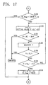
FIG. 17 is a flow chart showing a second part of the
procedure;
FIG. 18 is a flow chart showing a third part of the
procedure;
FIG. 19 is a graph illustrating a procedure of focus
offset adjustment processing to be executed when the device
is initiated into operation;
FIG. 20 is a graph illustrating a procedure of focus
offset adjustment processing to be executed when the device
is in the usual operation.
BEST MODE OF CARRYING OUT THE INVENTION
With reference to the drawings, a detailed description
will be given below of the present invention as embodied into
disk recording-playback devices for use with magneto-optical
disks serving as recording media.
FIG. 1 shows a disk recording-playback device embodying
the invention and comprising a spindle motor 2 for rotatingly
driving a magneto-optical disk 1, a magnetic head 3 and an
optical head 5 provided above and below the magneto-optical
disk 1, respectively. A magnetic head drive circuit 4 is
connected to the magnetic head 3 while a laser drive circuit
6 is connected to the optical head 5. Connected to the
magnetic head drive circuit 4 and the laser drive circuit 6
is a control circuit 7, which controls recording/reproduction
operations of signals. An output signal of the optical head
5 is fed to the control circuit 7, and output to a subsequent
circuit as reproduced data after processing such as
amplification, detection of reproduction signals, and error
correction.
Further, a servo circuit 9 is connected to the spindle
motor 2 and the optical head 5. An FE signal and a TE signal
obtained from the output signal of the optical head 5 are fed
to the servo circuit 9 from the control circuit 7. In
response to the FE signal and TE signal, focus servo and
tracking servo for an actuator (not shown) provided for the
optical head 5 are executed. Furthermore, an external
synchronizing signal is fed to the servo circuit 9 from the
control circuit 7, and the rotation of the spindle motor 2 is
controlled based on the signal.
Furthermore, provided opposed to the magneto-optical
disk 1 is a temperature sensor 8 for measuring a temperature
of the magneto-optical disk 1. An output terminal of the
temperature sensor 8 is connected to the control circuit 7,
where, based on temperature data obtained from the
temperature sensor 8, an offset adjustment procedure as will
be described below is executed, determining optimum offset
values respectively for the FE signal and the TE signal,
making the offset adjustment for the FE signal and the TE
signal with reference to the respective optimum offset
values. The FE signal and the TE signal given the offset
adjustment are input to the servo circuit 9, and are fed to
focus servo and tracking servo.
FIG. 2 shows a procedure to be executed by the control
circuit 7 in an initiation into operation of the disk
recording-playback device. When the device is turned on,
first in step S1 various gains of the servo circuit 9 are set
at initial values. In step S2 an offset value for focus is
adjusted based on the TE signal.
Next in step S3 an offset value for tracking is adjusted
based on the TE signal, and thereafter in step S4 each of a
recording power and reproduction power is set at an initial
value. Then in step S5 a gain necessary for reading out
address information recorded on the magneto-optical disk
(address gain) and a gain necessary for reading out an FCM
(fine clock mark) (FCM gain) are set at initial values.
Subsequently in step S6 the offset value for focus is
adjusted based on the RF signal, and thereafter in step S7
the reproduction power is adjusted. Then in step S8 a servo
gain for focus and a servo gain for tracking are adjusted,
and thereafter in step S9 the address gain and FCM gain are
adjusted. A series of the adjustment processing of step S6
to step S9 is executed for each of the lands and grooves of
the test tracks pre-provided on the magneto-optical disk.
Then in step S10 the recording power is adjusted for
each of the lands and grooves of the test tracks. In step
S11 current values of parameters adjusted as described are
checked. Lastly in step S12 the current values of those
parameters are stored in a built-in memory, and thereafter in
step S13 a current disk temperature T0 is stored in the
built-in memory to terminate the procedure.
In the focus offset adjustment processing of step S2 and
step S6 described, as seen in FIG. 10, focus offset values
are respectively set at at least five different values P0 to
P4 centered about an initial value P0, and amplitude values of
the TE signal or the RF signal at the respective offset
values are measured. Among said at least five points
measured, a first point is set at a point having the maximum
amplitude value, a second point is set at a point having an
offset value smaller than the offset value P0 at the first
point and an amplitude value not greater than a value (T0 -
5) obtained by subtracting a predetermined value from an
amplitude value T0 at the first point, a third point is set
at a point having an offset value greater than the offset
value P0 at the first point and an amplitude value not
greater than the value (T0 - 5) obtained by subtracting the
predetermined value from the amplitude value T0 at the first
point. With reference to the offset values P0, P1, P4 and the
amplitude values T0, T1, T4 at the respective three points, a
quadratic curve representing the relationship between the
offset values and the amplitude values is determined. An
offset value corresponding to the peak of the quadratic curve
is determined as an optimum offset value Popt1. This procedure
is the same as an offset adjustment processing to be executed
when a conventional disk recording-playback device is
initiated into operation.
FIGS. 3 to 5 show a specific procedure of the offset
adjustment processing to be executed in step S2 described. A
procedure of step S21 in FIG. 3 to step S43 in FIG. 5 is the
same as the conventional procedure shown in FIGS. 13 to 15.
In the case where the second point and the third point are
included in four measured points other than the first point
from among the five points measured, with reference to data
on the first to third points (Pmax, Tmax), (PA, TA) and (PB, TB)
which are included in the five points measured, the
relationship between the offset values and the amplitude
values is approximated to a quadratic curve, calculating an
offset value corresponding to the peak of the quadratic curve
as an optimum offset value Popt in step S43 in FIG. 5.
On the other hand, when the second point is not included
in the four measured points other than the first point, the
second point is retrieved in steps S30 to S35 in FIG. 4.
Data on the second point (PA, TA) retrieved is used when the
relationship between the offset values and the amplitude
values is approximated to a quadratic curve in step S43 in
FIG. 5.
Furthermore, when the third point is not included in the
four measured points other than the first point, the third
point is retrieved in steps S37 to S42 in FIG. 5. Data on
the third point (PB, TB) retrieved is used when the
relationship between the offset values and the amplitude
values is approximated to a quadratic curve in step S43.
In step S43 the optimum offset value is determined as
described, thereafter followed by step S44 wherein the offset
value PA at the second point and the offset value PB at the
third point are stored in a built-in memory, to terminate the
procedure.
Accordingly, the optimum offset value Popt for the focus
error is determined based on the TE signal, and the focus
offset adjustment is made with reference to the optimum
offset value Popt. Further, in the offset adjustment
processing to be executed in step S6 in FIG. 2, which is the
same as the processing shown in FIGS. 3 to 5, an optimum
offset value for the focus error is determined based on the
RF signal, and a focus offset adjustment is made based on the
optimum offset value.
With the disk recording-playback device described, the
focus offset adjustment is made based on the TE signal, as
described, while the focus offset adjustment is made based on
the RF signal, and signal reproduction and signal recording
are thereafter started.
FIG. 6 shows a procedure to be executed by the control
circuit 7 in a usual operation for signal reproduction and
signal recording after the system's initiation into
operation. When the usual operation is started, first in
step S51 a past disk temperature Told is set at a temperature
T0 stored in the built-in memory in the initiation into
operation of the device as described. In step S52 after the
elapse of a predetermined period of time, a current disk
temperature Tnow is measured.
Subsequently in step S53 an inquiry is made as to
whether the current disk temperature Tnow is not less than a
temperature (Told + Tthr) obtained by adding the past disk
temperature Told to a predetermined temperature Tthr. When the
answer is negative, the sequence returns to step S52 to
repeat the same procedure. Here, the predetermined
temperature Tthr is set at 5 °C, for example.
When variations of the disk temperature in excess of or
equal to the predetermined temperature Tthr make the answer
for step S53 affirmative, the sequence proceeds to step S54
wherein an inquiry is made as to whether the device is set
capable of adjusting various parameters in accordance with
temperature variations of the disk. When the answer for step
S54 is negative, the sequence returns to step S52. On the
other hand, when the answer is affirmative, step S55 follows
to adjust the reproduction power, and thereafter in step S56
the recording power is adjusted.
Then in step S57 the focus offset value is adjusted
based on the RF signal, and thereafter in step S58 the focus
offset value is adjusted based on the TE signal. Lastly in
step S59 current values of parameters adjusted as described
are stored in the built-in memory, and thereafter in step S60
the past disk temperature Told is set at the current disk
temperature Tnow. Then the sequence returns to step S52.
According to the procedure described, every time variations
in temperature of the disk in excess of or equal to a
predetermined temperature occur, the focus offset adjustment
processing is repeated.
In the previous offset adjustment processing, for
example, as seen in FIG. 10, the second and third offset
values P1, P4 each has an amplitude value smaller than the
amplitude value T0 at the first offset value P0 by a
predetermined value or more. Further, the optimum offset
value Topt1 has an amplitude value greater than the amplitude
value T0 at the first offset value P0. Thus the second and
third offset values P1, P4 each has an amplitude value smaller
than an amplitude value Topt1 at the optimum offset value Popt1
by a predetermined value or more.
Furthermore, when the disk recording-playback device is
in the usual reproduction operation, there is little change
in the quadratic curve representing the relationship between
the offset values and the amplitude values. Accordingly,
also in the current offset adjustment processing, amplitude
values T1, T4 at the second and third offset values P1, P4
obtained in the previous offset adjustment processing have a
very high possibility of being smaller than the amplitude
value Topt1 at the previous optimum offset value Popt1 by a
predetermined value or more, as seen in FIG. 11.
In the focus offset adjustment processing in step S57
and step S58 shown in FIG. 6, focus offset values are
respectively set at the optimum offset value Popt1 determined
in the previous offset adjustment processing, i.e., the set
value concerned, and the previous second offset value P1 and
the previous third offset value P4, as seen in FIG. 11, and
amplitude values at the respective offset values for the TE
signal or the RF signal are measured. When the second offset
value P1 and the third offset value P4 each has an amplitude
value not greater than a value (Topt1 - 5) obtained by
subtracting a predetermined value from the optimum offset
value Popt1, a quadratic curve representing the relationship
between the offset values and the amplitude values is
determined with reference to the offset values Popt1, P1, P4
and the amplitude values Topt1, T1, T4 at the respective three
measured point. An offset value corresponding to the peak of
the quadratic curve is determined as an optimum offset value
Popt2.
FIGS. 7 to 9 show a specific procedure of the focus
offset adjustment processing to be executed in step S57
described. First in step S61 in FIG. 7, set to "FALSE" are a
PA_flag and a PB_flag indicating whether the second and third
offset values PA, PB are each obtained. In step S62, a focus
offset value is set at a set value P0' concerned, i.e., the
previous optimum offset value, and an amplitude value T0' for
an RF signal is measured.
Subsequently in step S63, a first offset value Pmax' is
set at the set value P0', and a first amplitude value Tmax' is
set at the measured amplitude value T0'. In step S64, offset
values are respectively set at the two values PA, PB stored in
the built-in memory, i.e., the second offset and the third
offset value used when the quadratic curve is determined in
the previous offset adjustment processing, and amplitude
values TA, TB at the respective offset values are measured.
Next in step S65, an inquiry is made as to whether the
measured amplitude value TA is smaller than the first
amplitude value Tmax' by five steps or more. If the inquiry
is answered in the affirmative, step S66 follows to set to
"TRUE" the PA_flag indicating whether the second offset value
is obtained, and thereafter followed by step S67.
In step S67, an inquiry is made as to whether the
measured amplitude value TB is smaller than the first
amplitude value Tmax' by five steps or more. If the inquiry
is answered in the affirmative, step S68 follows to set to
"TRUE" the PB_flag indicating whether the third offset value
is obtained, and thereafter followed by step S69 in FIG. 8.
When the amplitude values TA, TB at the previous second
offset value PA and the third offset value PB are both smaller
than the first amplitude value Tmax' by five steps or more,
inquiries in step S69 in FIG. 8 and in step S76 in FIG. 9 are
answered in the affirmative. Then step S83 follows wherein
the relationship between the offset values and the amplitude
values is approximated to a quadratic curve with reference to
the data on the three measured points (Pmax', Tmax'), (PA, TA)
and (PB, TB), and an offset value corresponding to the peak of
the quadratic curve is calculated to be an optimum offset
value Popt. Lastly in step S84, the second offset value PA and
the third offset value PB are stored in the built-in memory,
to terminate the procedure. Accordingly, a new optimum
offset value Popt is obtained with reference to the optimum
offset value and the second and third offset values which are
obtained in the previous offset adjustment processing, and
the amplitude values at the respective offset values.
On the other hand, when the amplitude value TA at the
previous second offset value PA is not smaller than the first
amplitude value Tmax' by five steps or more, an inquiry in
step S69 in FIG. 8 is answered in the negative. In steps S70
to S75, an offset value is decreased starting from a value
smaller than the offset value PA by four steps, to thereby
vary the offset value until when an amplitude value T becomes
a value smaller than the first amplitude value Tmax' by five
steps or more. Then a second offset value PA and a second
amplitude value TA are respectively set at the offset value
and the amplitude value concerned. The second point is thus
retrieved. Thereafter in step S83 in FIG. 9, when the
relationship between the offset values and the amplitude
values is approximated to a quadratic curve, the retrieved
data (PA, TA) on the second point is referred to. However,
when an offset value becomes a value smaller than the
previous optimum offset value by 20 steps or more to make the
answer in step S71 affirmative, and when an amplitude value T
is not greater than a lower limit value TL to make the answer
in step S73 affirmative, focus servo deviates, to thereby
terminate the procedure.
Furthermore, when the amplitude value TB at the previous
third offset value PB is not smaller than the first amplitude
value Tmax' by five steps or more, an inquiry in step S76 in
FIG. 9 is answered in the negative. In steps S77 to S82, an
offset value is increased starting from a value greater than
the offset value PB by four steps, to thereby vary the offset
value until when the amplitude value T becomes a value
smaller than the first amplitude value Tmax' by five steps or
more. Then a third offset value PB and a third amplitude
value TB are respectively set at the offset value and the
amplitude value concerned. The third point is thus retrieved.
Thereafter in step S83, when the relationship between the
offset values and the amplitude values is approximated to a
quadratic curve, the retrieved data (PB, TB) on the third
point is referred to. However, when an offset value becomes
a value greater than the previous optimum offset value by 20
steps or more to make the answer in step S78 affirmative, and
when an amplitude value is not greater than a lower limit
value TL to make the answer in step S80 affirmative, focus
servo deviates, to thereby terminate the procedure.
Accordingly, the optimum offset value Popt for the focus
error is obtained based on the RF signals, to thereby make a
focus offset adjustment based on the optimum offset value.
Furthermore, in the offset adjustment processing to be
executed in step S58 in FIG. 6, the optimum offset value for
the focus error is obtained based on the TF signals according
to the same procedure as that in FIGS. 7 to 9, to thereby
make a focus offset adjustment based on the offset value.
Consequently, focus servo is effected with high accuracy at
all times despite variations in temperature of the magneto-optical
disk.
In the focus offset adjustment processing to be executed
in the usual operation of the disk recording-playback device
embodying the present invention, the amplitude values each at
the previous offset value Popt1, the previous second offset
value P1, and the previous third offset value P4 is measured,
as seen in FIG. 11. When the amplitude values at the second
and third offset values P1, P4 are both smaller than the
amplitude value at the optimum offset value Popt1 by five
steps or more, the quadratic curve representing the
relationship between the offset values and the amplitude
values is determined with reference to the offset values and
the amplitude values at the three measured points. This
makes a period of time required for the determination of the
quadratic curve shorter than conventionally, because, with
the conventional disk recording-playback device, the
amplitude values need be measured at at least five points.
Consequently, a period of time taken for deriving the optimum
offset value is reduced.
Furthermore, when the amplitude value at the previous
second offset value fails to be a value smaller than the
amplitude value at the previous optimum offset value by five
steps or more, a new offset value is retrieved wherein an
amplitude value is a value smaller than the amplitude value
at the previous optimum offset value by five steps or more,
as shown in FIG. 8. Further, when the amplitude value at the
previous third offset value fails to be a value smaller than
the amplitude value at the previous optimum offset value by
five steps or more, a new offset value is retrieved wherein
an amplitude value is a value smaller than the amplitude
value at the previous optimum offset value by five steps or
more, as shown in FIG. 9. Thereafter, a quadratic curve is
determined with reference to the offset value thus retrieved.
Accordingly, the quadratic curve is determined with high
accuracy constantly, to thereby obtain the optimum offset
value with high accuracy at all times.
The present invention is not limited to the foregoing
embodiment in construction but can be modified variously
within the technical scope defined in the appended claims.
For example, in the usual operation, tracking offset
adjustment processing can be performed. In this case the
optimum offset value can be obtained in accordance with the
procedure shown in FIG. 11.