EP1548718A1 - Disc reproduction device - Google Patents
Disc reproduction device Download PDFInfo
- Publication number
- EP1548718A1 EP1548718A1 EP03766640A EP03766640A EP1548718A1 EP 1548718 A1 EP1548718 A1 EP 1548718A1 EP 03766640 A EP03766640 A EP 03766640A EP 03766640 A EP03766640 A EP 03766640A EP 1548718 A1 EP1548718 A1 EP 1548718A1
- Authority
- EP
- European Patent Office
- Prior art keywords
- value
- offset
- amplitude
- offset value
- values
- Prior art date
- Legal status (The legal status is an assumption and is not a legal conclusion. Google has not performed a legal analysis and makes no representation as to the accuracy of the status listed.)
- Withdrawn
Links
Images








Classifications
-
- G—PHYSICS
- G11—INFORMATION STORAGE
- G11B—INFORMATION STORAGE BASED ON RELATIVE MOVEMENT BETWEEN RECORD CARRIER AND TRANSDUCER
- G11B7/00—Recording or reproducing by optical means, e.g. recording using a thermal beam of optical radiation by modifying optical properties or the physical structure, reproducing using an optical beam at lower power by sensing optical properties; Record carriers therefor
- G11B7/12—Heads, e.g. forming of the optical beam spot or modulation of the optical beam
- G11B7/125—Optical beam sources therefor, e.g. laser control circuitry specially adapted for optical storage devices; Modulators, e.g. means for controlling the size or intensity of optical spots or optical traces
- G11B7/126—Circuits, methods or arrangements for laser control or stabilisation
- G11B7/1267—Power calibration
-
- G—PHYSICS
- G11—INFORMATION STORAGE
- G11B—INFORMATION STORAGE BASED ON RELATIVE MOVEMENT BETWEEN RECORD CARRIER AND TRANSDUCER
- G11B7/00—Recording or reproducing by optical means, e.g. recording using a thermal beam of optical radiation by modifying optical properties or the physical structure, reproducing using an optical beam at lower power by sensing optical properties; Record carriers therefor
- G11B7/08—Disposition or mounting of heads or light sources relatively to record carriers
- G11B7/09—Disposition or mounting of heads or light sources relatively to record carriers with provision for moving the light beam or focus plane for the purpose of maintaining alignment of the light beam relative to the record carrier during transducing operation, e.g. to compensate for surface irregularities of the latter or for track following
-
- G—PHYSICS
- G11—INFORMATION STORAGE
- G11B—INFORMATION STORAGE BASED ON RELATIVE MOVEMENT BETWEEN RECORD CARRIER AND TRANSDUCER
- G11B11/00—Recording on or reproducing from the same record carrier wherein for these two operations the methods are covered by different main groups of groups G11B3/00 - G11B7/00 or by different subgroups of group G11B9/00; Record carriers therefor
- G11B11/10—Recording on or reproducing from the same record carrier wherein for these two operations the methods are covered by different main groups of groups G11B3/00 - G11B7/00 or by different subgroups of group G11B9/00; Record carriers therefor using recording by magnetic means or other means for magnetisation or demagnetisation of a record carrier, e.g. light induced spin magnetisation; Demagnetisation by thermal or stress means in the presence or not of an orienting magnetic field
- G11B11/105—Recording on or reproducing from the same record carrier wherein for these two operations the methods are covered by different main groups of groups G11B3/00 - G11B7/00 or by different subgroups of group G11B9/00; Record carriers therefor using recording by magnetic means or other means for magnetisation or demagnetisation of a record carrier, e.g. light induced spin magnetisation; Demagnetisation by thermal or stress means in the presence or not of an orienting magnetic field using a beam of light or a magnetic field for recording by change of magnetisation and a beam of light for reproducing, i.e. magneto-optical, e.g. light-induced thermomagnetic recording, spin magnetisation recording, Kerr or Faraday effect reproducing
- G11B11/1055—Disposition or mounting of transducers relative to record carriers
- G11B11/10576—Disposition or mounting of transducers relative to record carriers with provision for moving the transducers for maintaining alignment or spacing relative to the carrier
-
- G—PHYSICS
- G11—INFORMATION STORAGE
- G11B—INFORMATION STORAGE BASED ON RELATIVE MOVEMENT BETWEEN RECORD CARRIER AND TRANSDUCER
- G11B11/00—Recording on or reproducing from the same record carrier wherein for these two operations the methods are covered by different main groups of groups G11B3/00 - G11B7/00 or by different subgroups of group G11B9/00; Record carriers therefor
- G11B11/10—Recording on or reproducing from the same record carrier wherein for these two operations the methods are covered by different main groups of groups G11B3/00 - G11B7/00 or by different subgroups of group G11B9/00; Record carriers therefor using recording by magnetic means or other means for magnetisation or demagnetisation of a record carrier, e.g. light induced spin magnetisation; Demagnetisation by thermal or stress means in the presence or not of an orienting magnetic field
- G11B11/105—Recording on or reproducing from the same record carrier wherein for these two operations the methods are covered by different main groups of groups G11B3/00 - G11B7/00 or by different subgroups of group G11B9/00; Record carriers therefor using recording by magnetic means or other means for magnetisation or demagnetisation of a record carrier, e.g. light induced spin magnetisation; Demagnetisation by thermal or stress means in the presence or not of an orienting magnetic field using a beam of light or a magnetic field for recording by change of magnetisation and a beam of light for reproducing, i.e. magneto-optical, e.g. light-induced thermomagnetic recording, spin magnetisation recording, Kerr or Faraday effect reproducing
- G11B11/10595—Control of operating function
- G11B11/10597—Adaptations for transducing various formats on the same or different carriers
-
- G—PHYSICS
- G11—INFORMATION STORAGE
- G11B—INFORMATION STORAGE BASED ON RELATIVE MOVEMENT BETWEEN RECORD CARRIER AND TRANSDUCER
- G11B7/00—Recording or reproducing by optical means, e.g. recording using a thermal beam of optical radiation by modifying optical properties or the physical structure, reproducing using an optical beam at lower power by sensing optical properties; Record carriers therefor
- G11B7/08—Disposition or mounting of heads or light sources relatively to record carriers
- G11B7/09—Disposition or mounting of heads or light sources relatively to record carriers with provision for moving the light beam or focus plane for the purpose of maintaining alignment of the light beam relative to the record carrier during transducing operation, e.g. to compensate for surface irregularities of the latter or for track following
- G11B7/094—Methods and circuits for servo offset compensation
-
- G—PHYSICS
- G11—INFORMATION STORAGE
- G11B—INFORMATION STORAGE BASED ON RELATIVE MOVEMENT BETWEEN RECORD CARRIER AND TRANSDUCER
- G11B7/00—Recording or reproducing by optical means, e.g. recording using a thermal beam of optical radiation by modifying optical properties or the physical structure, reproducing using an optical beam at lower power by sensing optical properties; Record carriers therefor
- G11B7/08—Disposition or mounting of heads or light sources relatively to record carriers
- G11B7/09—Disposition or mounting of heads or light sources relatively to record carriers with provision for moving the light beam or focus plane for the purpose of maintaining alignment of the light beam relative to the record carrier during transducing operation, e.g. to compensate for surface irregularities of the latter or for track following
- G11B7/0945—Methods for initialising servos, start-up sequences
-
- G—PHYSICS
- G11—INFORMATION STORAGE
- G11B—INFORMATION STORAGE BASED ON RELATIVE MOVEMENT BETWEEN RECORD CARRIER AND TRANSDUCER
- G11B7/00—Recording or reproducing by optical means, e.g. recording using a thermal beam of optical radiation by modifying optical properties or the physical structure, reproducing using an optical beam at lower power by sensing optical properties; Record carriers therefor
- G11B7/08—Disposition or mounting of heads or light sources relatively to record carriers
- G11B7/09—Disposition or mounting of heads or light sources relatively to record carriers with provision for moving the light beam or focus plane for the purpose of maintaining alignment of the light beam relative to the record carrier during transducing operation, e.g. to compensate for surface irregularities of the latter or for track following
- G11B7/095—Disposition or mounting of heads or light sources relatively to record carriers with provision for moving the light beam or focus plane for the purpose of maintaining alignment of the light beam relative to the record carrier during transducing operation, e.g. to compensate for surface irregularities of the latter or for track following specially adapted for discs, e.g. for compensation of eccentricity or wobble
-
- G—PHYSICS
- G11—INFORMATION STORAGE
- G11B—INFORMATION STORAGE BASED ON RELATIVE MOVEMENT BETWEEN RECORD CARRIER AND TRANSDUCER
- G11B7/00—Recording or reproducing by optical means, e.g. recording using a thermal beam of optical radiation by modifying optical properties or the physical structure, reproducing using an optical beam at lower power by sensing optical properties; Record carriers therefor
- G11B7/007—Arrangement of the information on the record carrier, e.g. form of tracks, actual track shape, e.g. wobbled, or cross-section, e.g. v-shaped; Sequential information structures, e.g. sectoring or header formats within a track
- G11B7/00718—Groove and land recording, i.e. user data recorded both in the grooves and on the lands
-
- G—PHYSICS
- G11—INFORMATION STORAGE
- G11B—INFORMATION STORAGE BASED ON RELATIVE MOVEMENT BETWEEN RECORD CARRIER AND TRANSDUCER
- G11B7/00—Recording or reproducing by optical means, e.g. recording using a thermal beam of optical radiation by modifying optical properties or the physical structure, reproducing using an optical beam at lower power by sensing optical properties; Record carriers therefor
- G11B7/08—Disposition or mounting of heads or light sources relatively to record carriers
- G11B7/09—Disposition or mounting of heads or light sources relatively to record carriers with provision for moving the light beam or focus plane for the purpose of maintaining alignment of the light beam relative to the record carrier during transducing operation, e.g. to compensate for surface irregularities of the latter or for track following
- G11B7/0941—Methods and circuits for servo gain or phase compensation during operation
Definitions
- the present invention relates to disk playback devices for reproducing signals from a disk by irradiating the disk with a laser beam from an optical head.
- magneto-optical disks For use as recording media in disk recording-playback devices, magneto-optical disks have been developed which permit rewriting and have a great memory capacity and high reliability. Such disks have found wide use as external memories in computers and audio visual devices.
- focus offset values are respectively set at at least five different values P 0 to P 4 centered about an initial value P 0 , and amplitude values of the TE signal at the respective offset values are measured.
- a first point is set at a point having the maximum amplitude value
- a second point is set at a point having an offset value smaller than the offset value P 0 at the first point and an amplitude value not greater than a value (T 0 - 5) obtained by subtracting a predetermined value from an amplitude value T 0 at the first point
- a third point is set at a point having an offset value greater than the offset value P 0 at the first point and an amplitude value not greater than the value (T 0 - 5) obtained by subtracting the predetermined value from the amplitude value T 0 at the first point.
- a quadratic curve representing the relationship between the offset values and the amplitude values is determined.
- An offset value corresponding to the peak of the quadratic curve is determined as an optimum offset value P opt1 ⁇
- a procedure for determining an optimum offset value based on the RF signals is the same as the above.
- step S95 an inquiry is made as to whether a second point having an offset value P x smaller than the first offset value P max and an amplitude value T x smaller than the first amplitude value T max by five steps or more is included in four measured points other than the first point. If the inquiry is answered in the affirmative, step S96 follows to set a second offset value P A at the offset value P x at the second point, set a second amplitude value T A at the amplitude value T x at the second point, and set to "TRUE" a P A _flag indicating whether the second offset value P A is obtained, thereafter followed by step S97.
- the relationship between the offset values and the amplitude values is approximated to a quadratic curve, the data (P A , T A ) at the retrieved second point is used.
- the offset value P is smaller than the initial value P 0 by 20 steps or more to make the answer to step S101 affirmative, or in the case where the amplitude value T is not greater than a lower limit value T L to make the answer to step S103 affirmative, focus servo deviates to terminate the procedure.
- step S113 When, in step S113, the relationship between the offset values and the amplitude values is approximated to a quadratic curve, the data (P B , T B ) at the retrieved third point is used.
- the offset value P is greater than the initial value P 0 by 20 steps or more to make the answer to step S108 affirmative, or in the case where the amplitude value T is not greater than a lower limit value T L to make the answer to step S110 affirmative, focus servo deviates to terminate the procedure.
- an offset adjustment for focusing is made every time a temperature of the disk varies by a predetermined temperature or more.
- a quadratic curve representing the relationship between the offset values and the amplitude values is determined.
- An offset value corresponding to the peak of the quadratic curve is determined as an optimum offset value P opt2 .
- a procedure of determining an optimum offset value based on the RF signals is the same as the above.
- focus offset values are respectively set at a set value concerned P 0 ', a value P 1 ' smaller than the set value by eight steps, a value P 2 ' smaller than the set value by four steps, a value P 3 ' greater than the set value by four steps, and a value P 4 ' greater than the set value by eight steps, and amplitude values T 0 ' to T 4 ' are measured at the respective offset values.
- the maximum amplitude value is a first point.
- An offset value at the first point is a first offset value P max '.
- An amplitude value at the first point is a first amplitude value T max '.
- step S125 an inquiry is made as to whether a second point having an offset value P x ' smaller than the first offset value P max ' and an amplitude value T x ' smaller than the first amplitude value T max ' by five steps or more is included in four measured points other than the first point. If the inquiry is answered in the affirmative, step S126 follows to set a second offset value P A at the offset value P x ' at the second point, set a second amplitude value T A at the amplitude value T x ' at the second point, and set to "TRUE" a P A _flag indicating whether the second offset value P A is obtained, thereafter followed by step S127.
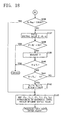
- step S143 When the second point and the third point are included in the four measured points other than the first point, answers to inquiries in step S129 in FIG. 17 and in step S136 in FIG. 18 are affirmative, followed by step S143.
- the relationship between the offset values and the amplitude values is approximated to a quadratic curve, and an offset value corresponding to the peak of the quadratic curve is calculated as an optimum offset value P opt ', to terminate the procedure.
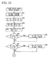
- a second point is retrieved according to the same procedure as that in an initiation operation as shown in steps S130 to S135 in FIG. 17.
- step S143 in FIG. 18 the relationship between the offset values and the amplitude values is approximated to a quadratic curve, data (P A , T A ) at the retrieved second point is used.
- the disk recording-playback device described has the following problem: in the offset adjustment procedure of the usual operation, the relationship between the offset values and the amplitude values is approximated to a quadratic curve with reference to the previous optimum offset value P opt1 , and the second and third offset values P 1 ', P 4 ' each having an amplitude value smaller than the amplitude value T opt1 at the offset value P opt1 by a predetermined value or more, as shown in FIG. 20, to increase accuracy of the quadratic curve.
- amplitude values at at least five different offset values P opt1 and P 1 ' to P 4 ' need be measured, requiring a long period of time for determining the quadratic curve, thereby entailing the problem of a long period of time taken for the calculation of the optimum offset value.
- the present invention provides a disk playback device comprising a calculation processing circuit for determining an optimum value of offset for an error signal based on an amplitude value of the error signal in accordance with focus deviation or tracking deviation of an optical head, or an amplitude value of an output signal of the optical head, and making an offset adjustment based on the optimum offset value.
- the calculation processing circuit approximates to a quadratic curve the relationship between offset values and the amplitude values in signal reproduction, and repeats calculation of the optimum offset values based on the quadratic curve.
- the calculation processing circuit comprises:
- the first offset value is set at an optimum offset value obtained in a previous optimum offset value calculation processing
- the second and third offset values are respectively set at second and third offset values set in a previous optimum offset value calculation processing.
- the second and third offset values set in the previous optimum offset value calculation processing each has an amplitude value smaller than an amplitude value at the first offset value by a predetermined value or more.
- the offset value corresponding to the peak of the quadratic curve is calculated as the optimum offset value, so that the optimum offset value obtained in the previous optimum offset value calculation processing has an amplitude value greater than the amplitude value at the first offset value.
- the second and the third offset values each has an amplitude value smaller than the amplitude value at the optimum offset value by a predetermined value or more.
- the quadratic curve representing the relationship between the offset values and the amplitude values shows little change. Therefore, also in the current offset value calculation processing, the amplitude values at the previous second and third offset values have a very high possibility of being smaller than the amplitude value at the previous optimum offset value by a predetermined value or more, whereby the quadratic curve can be determined with high accuracy with reference to the previous optimum offset value, the second and third offset values, and the amplitude values at the respective offset values.
- the amplitude values at the previous second and third offset values have a very high possibility of being smaller than the amplitude value at the previous optimum offset value by a predetermined value or more, but the amplitude values fail to be smaller than the value by a predetermined value or more as the case may be.
- the quadratic curve when the quadratic curve is determined with reference to the previous optimum offset value and the previous second and third offset values, the quadratic curve has a low accuracy, thereby impairing the accuracy of the optimum offset value corresponding to the peak of the quadratic curve.
- retrieved is an offset value having an amplitude value smaller than the amplitude value at the previous optimum offset value by a predetermined value or more, to determine a quadratic curve by setting a second offset value at the retrieved offset value.
- retrieved is an offset value having an amplitude value smaller than the amplitude value at the previous optimum offset value by a predetermined value or more, to determine a quadratic curve by setting a third offset value at the retrieved offset value. Accordingly, the quadratic curve can be determined with high accuracy, to thereby obtain the optimum offset value with high accuracy at all times.
- the disk playback device comprises temperature detection means for detecting a temperature of the disk.
- the calculation processing circuit calculates the optimum offset value every time the disk is varied in temperature by a predetermined temperature value.
- the optimum offset value is obtained. Based on the optimum offset value obtained, an offset adjustment is made. This reproduces an error signal given the optimum offset adjustment in accordance with temperature variations, whereby focusing of the optical head or tracking is controlled with high accuracy based on the error signal.
- the optimum value of offset for the error signals can be obtained in a short period of time when the device is in the usual operation.
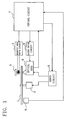
- FIG. 1 shows a disk recording-playback device embodying the invention and comprising a spindle motor 2 for rotatingly driving a magneto-optical disk 1, a magnetic head 3 and an optical head 5 provided above and below the magneto-optical disk 1, respectively.
- a magnetic head drive circuit 4 is connected to the magnetic head 3 while a laser drive circuit 6 is connected to the optical head 5.
- a control circuit 7, Connected to the magnetic head drive circuit 4 and the laser drive circuit 6 is a control circuit 7, which controls recording/reproduction operations of signals.
- An output signal of the optical head 5 is fed to the control circuit 7, and output to a subsequent circuit as reproduced data after processing such as amplification, detection of reproduction signals, and error correction.
- a servo circuit 9 is connected to the spindle motor 2 and the optical head 5.
- An FE signal and a TE signal obtained from the output signal of the optical head 5 are fed to the servo circuit 9 from the control circuit 7.
- focus servo and tracking servo for an actuator (not shown) provided for the optical head 5 are executed.
- an external synchronizing signal is fed to the servo circuit 9 from the control circuit 7, and the rotation of the spindle motor 2 is controlled based on the signal.
- a temperature sensor 8 for measuring a temperature of the magneto-optical disk 1.
- An output terminal of the temperature sensor 8 is connected to the control circuit 7, where, based on temperature data obtained from the temperature sensor 8, an offset adjustment procedure as will be described below is executed, determining optimum offset values respectively for the FE signal and the TE signal, making the offset adjustment for the FE signal and the TE signal with reference to the respective optimum offset values.
- the FE signal and the TE signal given the offset adjustment are input to the servo circuit 9, and are fed to focus servo and tracking servo.
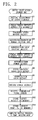
- FIG. 2 shows a procedure to be executed by the control circuit 7 in an initiation into operation of the disk recording-playback device.
- step S1 various gains of the servo circuit 9 are set at initial values.
- step S2 an offset value for focus is adjusted based on the TE signal.
- step S3 an offset value for tracking is adjusted based on the TE signal, and thereafter in step S4 each of a recording power and reproduction power is set at an initial value. Then in step S5 a gain necessary for reading out address information recorded on the magneto-optical disk (address gain) and a gain necessary for reading out an FCM (fine clock mark) (FCM gain) are set at initial values.
- address gain a gain necessary for reading out address information recorded on the magneto-optical disk
- FCM fine clock mark
- step S6 the offset value for focus is adjusted based on the RF signal, and thereafter in step S7 the reproduction power is adjusted. Then in step S8 a servo gain for focus and a servo gain for tracking are adjusted, and thereafter in step S9 the address gain and FCM gain are adjusted.
- step S6 the offset value for focus is adjusted based on the RF signal
- step S8 the reproduction power is adjusted.
- step S8 a servo gain for focus and a servo gain for tracking are adjusted, and thereafter in step S9 the address gain and FCM gain are adjusted.
- a series of the adjustment processing of step S6 to step S9 is executed for each of the lands and grooves of the test tracks pre-provided on the magneto-optical disk.
- step S10 the recording power is adjusted for each of the lands and grooves of the test tracks.
- step S11 current values of parameters adjusted as described are checked.
- step S12 the current values of those parameters are stored in a built-in memory, and thereafter in step S13 a current disk temperature T 0 is stored in the built-in memory to terminate the procedure.
- focus offset values are respectively set at at least five different values P 0 to P 4 centered about an initial value P 0 , and amplitude values of the TE signal or the RF signal at the respective offset values are measured.
- a first point is set at a point having the maximum amplitude value
- a second point is set at a point having an offset value smaller than the offset value P 0 at the first point and an amplitude value not greater than a value (T 0 - 5) obtained by subtracting a predetermined value from an amplitude value T 0 at the first point
- a third point is set at a point having an offset value greater than the offset value P 0 at the first point and an amplitude value not greater than the value (T 0 - 5) obtained by subtracting the predetermined value from the amplitude value T 0 at the first point.
- a quadratic curve representing the relationship between the offset values and the amplitude values is determined.
- An offset value corresponding to the peak of the quadratic curve is determined as an optimum offset value P opt1 .
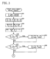
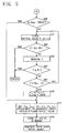
- FIGS. 3 to 5 show a specific procedure of the offset adjustment processing to be executed in step S2 described.
- a procedure of step S21 in FIG. 3 to step S43 in FIG. 5 is the same as the conventional procedure shown in FIGS. 13 to 15.
- the relationship between the offset values and the amplitude values is approximated to a quadratic curve, calculating an offset value corresponding to the peak of the quadratic curve as an optimum offset value P opt in step S43 in FIG. 5.
- the second point is retrieved in steps S30 to S35 in FIG. 4.
- Data on the second point (P A , T A ) retrieved is used when the relationship between the offset values and the amplitude values is approximated to a quadratic curve in step S43 in FIG. 5.
- the third point is retrieved in steps S37 to S42 in FIG. 5.
- Data on the third point (P B , T B ) retrieved is used when the relationship between the offset values and the amplitude values is approximated to a quadratic curve in step S43.
- step S43 the optimum offset value is determined as described, thereafter followed by step S44 wherein the offset value P A at the second point and the offset value P B at the third point are stored in a built-in memory, to terminate the procedure.
- the optimum offset value P opt for the focus error is determined based on the TE signal, and the focus offset adjustment is made with reference to the optimum offset value P opt . Further, in the offset adjustment processing to be executed in step S6 in FIG. 2, which is the same as the processing shown in FIGS. 3 to 5, an optimum offset value for the focus error is determined based on the RF signal, and a focus offset adjustment is made based on the optimum offset value.
- the focus offset adjustment is made based on the TE signal, as described, while the focus offset adjustment is made based on the RF signal, and signal reproduction and signal recording are thereafter started.
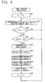
- FIG. 6 shows a procedure to be executed by the control circuit 7 in a usual operation for signal reproduction and signal recording after the system's initiation into operation.
- a past disk temperature T old is set at a temperature T 0 stored in the built-in memory in the initiation into operation of the device as described.
- a current disk temperature T now is measured.
- step S53 an inquiry is made as to whether the current disk temperature T now is not less than a temperature (T old + T thr ) obtained by adding the past disk temperature T old to a predetermined temperature T thr .
- the predetermined temperature T thr is set at 5 °C, for example.
- step S53 When variations of the disk temperature in excess of or equal to the predetermined temperature T thr make the answer for step S53 affirmative, the sequence proceeds to step S54 wherein an inquiry is made as to whether the device is set capable of adjusting various parameters in accordance with temperature variations of the disk. When the answer for step S54 is negative, the sequence returns to step S52. On the other hand, when the answer is affirmative, step S55 follows to adjust the reproduction power, and thereafter in step S56 the recording power is adjusted.
- step S57 the focus offset value is adjusted based on the RF signal, and thereafter in step S58 the focus offset value is adjusted based on the TE signal.
- step S59 current values of parameters adjusted as described are stored in the built-in memory, and thereafter in step S60 the past disk temperature T old is set at the current disk temperature T now . Then the sequence returns to step S52. According to the procedure described, every time variations in temperature of the disk in excess of or equal to a predetermined temperature occur, the focus offset adjustment processing is repeated.
- the second and third offset values P 1 , P 4 each has an amplitude value smaller than the amplitude value T 0 at the first offset value P 0 by a predetermined value or more. Further, the optimum offset value T opt1 has an amplitude value greater than the amplitude value T 0 at the first offset value P 0 . Thus the second and third offset values P 1 , P 4 each has an amplitude value smaller than an amplitude value T opt1 at the optimum offset value P opt1 by a predetermined value or more.
- amplitude values T 1 , T 4 at the second and third offset values P 1 , P 4 obtained in the previous offset adjustment processing have a very high possibility of being smaller than the amplitude value T opt1 at the previous optimum offset value P opt1 by a predetermined value or more, as seen in FIG. 11.
- focus offset values are respectively set at the optimum offset value P opt1 determined in the previous offset adjustment processing, i.e., the set value concerned, and the previous second offset value P 1 and the previous third offset value P 4 , as seen in FIG. 11, and amplitude values at the respective offset values for the TE signal or the RF signal are measured.
- the second offset value P 1 and the third offset value P 4 each has an amplitude value not greater than a value (T opt1 - 5) obtained by subtracting a predetermined value from the optimum offset value P opt1 , a quadratic curve representing the relationship between the offset values and the amplitude values is determined with reference to the offset values P opt1 , P 1 , P 4 and the amplitude values T opt1 , T 1 , T 4 at the respective three measured point.
- An offset value corresponding to the peak of the quadratic curve is determined as an optimum offset value P opt2 .
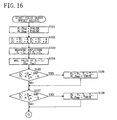
- FIGS. 7 to 9 show a specific procedure of the focus offset adjustment processing to be executed in step S57 described.
- step S61 in FIG. 7 set to "FALSE" are a P A _flag and a P B _flag indicating whether the second and third offset values P A , P B are each obtained.
- step S62 a focus offset value is set at a set value P 0 ' concerned, i.e., the previous optimum offset value, and an amplitude value T 0 ' for an RF signal is measured.
- step S63 a first offset value P max ' is set at the set value P 0 ', and a first amplitude value T max ' is set at the measured amplitude value T 0 '.
- step S64 offset values are respectively set at the two values P A , P B stored in the built-in memory, i.e., the second offset and the third offset value used when the quadratic curve is determined in the previous offset adjustment processing, and amplitude values T A , T B at the respective offset values are measured.
- step S65 an inquiry is made as to whether the measured amplitude value T A is smaller than the first amplitude value T max ' by five steps or more. If the inquiry is answered in the affirmative, step S66 follows to set to "TRUE" the P A _flag indicating whether the second offset value is obtained, and thereafter followed by step S67.
- step S67 an inquiry is made as to whether the measured amplitude value T B is smaller than the first amplitude value T max ' by five steps or more. If the inquiry is answered in the affirmative, step S68 follows to set to "TRUE" the P B _flag indicating whether the third offset value is obtained, and thereafter followed by step S69 in FIG. 8.
- step S83 follows wherein the relationship between the offset values and the amplitude values is approximated to a quadratic curve with reference to the data on the three measured points (P max ', T max '), (P A , T A ) and (P B , T B ), and an offset value corresponding to the peak of the quadratic curve is calculated to be an optimum offset value P opt .
- step S84 the second offset value P A and the third offset value P B are stored in the built-in memory, to terminate the procedure. Accordingly, a new optimum offset value P opt is obtained with reference to the optimum offset value and the second and third offset values which are obtained in the previous offset adjustment processing, and the amplitude values at the respective offset values.
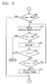
- step S69 in FIG. 8 an inquiry in step S69 in FIG. 8 is answered in the negative.
- steps S70 to S75 an offset value is decreased starting from a value smaller than the offset value P A by four steps, to thereby vary the offset value until when an amplitude value T becomes a value smaller than the first amplitude value T max ' by five steps or more.
- a second offset value P A and a second amplitude value T A are respectively set at the offset value and the amplitude value concerned. The second point is thus retrieved.
- step S76 in FIG. 9 an inquiry in step S76 in FIG. 9 is answered in the negative.
- steps S77 to S82 an offset value is increased starting from a value greater than the offset value P B by four steps, to thereby vary the offset value until when the amplitude value T becomes a value smaller than the first amplitude value T max ' by five steps or more.
- a third offset value P B and a third amplitude value T B are respectively set at the offset value and the amplitude value concerned. The third point is thus retrieved.
- step S83 when the relationship between the offset values and the amplitude values is approximated to a quadratic curve, the retrieved data (P B , T B ) on the third point is referred to.
- an offset value becomes a value greater than the previous optimum offset value by 20 steps or more to make the answer in step S78 affirmative, and when an amplitude value is not greater than a lower limit value T L to make the answer in step S80 affirmative, focus servo deviates, to thereby terminate the procedure.
- the optimum offset value P opt for the focus error is obtained based on the RF signals, to thereby make a focus offset adjustment based on the optimum offset value. Furthermore, in the offset adjustment processing to be executed in step S58 in FIG. 6, the optimum offset value for the focus error is obtained based on the TF signals according to the same procedure as that in FIGS. 7 to 9, to thereby make a focus offset adjustment based on the offset value. Consequently, focus servo is effected with high accuracy at all times despite variations in temperature of the magneto-optical disk.
- the amplitude values each at the previous offset value P opt1 , the previous second offset value P 1 , and the previous third offset value P 4 is measured, as seen in FIG. 11.
- the quadratic curve representing the relationship between the offset values and the amplitude values is determined with reference to the offset values and the amplitude values at the three measured points.
- a new offset value is retrieved wherein an amplitude value is a value smaller than the amplitude value at the previous optimum offset value by five steps or more, as shown in FIG. 8.
- a new offset value is retrieved wherein an amplitude value is a value smaller than the amplitude value at the previous optimum offset value by five steps or more, as shown in FIG. 9.
- a quadratic curve is determined with reference to the offset value thus retrieved. Accordingly, the quadratic curve is determined with high accuracy constantly, to thereby obtain the optimum offset value with high accuracy at all times.
- tracking offset adjustment processing can be performed.
- the optimum offset value can be obtained in accordance with the procedure shown in FIG. 11.
Landscapes
- Physics & Mathematics (AREA)
- Optics & Photonics (AREA)
- Optical Recording Or Reproduction (AREA)
Abstract
Description
Claims (3)
- A disk playback device comprising a calculation processing circuit for determining an optimum value of offset for an error signal based on an amplitude value of the error signal in accordance with focus deviation or tracking deviation of an optical head or an amplitude value of an output signal of the optical head, and making an offset adjustment based on the optimum offset value, the calculation processing circuit approximating to a quadratic curve the relationship between offset values and the amplitude values in signal reproduction, and repeating calculation of the optimum offset values based on the quadratic curve, and comprising:the value setting means setting the first offset value at an optimum offset value obtained in a previous optimum offset value calculation processing, and setting the second and third offset values respectively at second and third offset values set in a previous optimum offset value calculation processing.calculation processing means for approximating to a quadratic curve the relationship between the offset values and the amplitude values with reference to three different offset values and three amplitude values at the respective offset values, and calculating an offset value corresponding to the peak of the quadratic curve as the optimum offset value, andvalue setting means for setting the three different offset values: a first offset value; a second offset value smaller than the first offset value and having an amplitude value smaller than an amplitude value at the first offset value by a predetermined value or more; a third offset value greater than the first offset value and having an amplitude value smaller than an amplitude value at the first offset value by a predetermined value or more, and setting the three amplitude values respectively at three amplitude values at the first to third offset values,
- A disk playback device according to claim 1 wherein the calculation processing circuit comprises:first checking means for checking whether an amplitude value at the previous second offset value is smaller than an amplitude value at the previous optimum offset value by a predetermined value or more,second checking means for checking whether an amplitude value at the previous third offset value is smaller than an amplitude value at the previous optimum offset value by a predetermined value or more, the value setting means comprising:second offset value setting means for retrieving an offset value having an amplitude value smaller than the amplitude value at the previous optimum offset value by a predetermined value or more when the amplitude value at the previous second offset value is not found to be smaller than the amplitude value at the previous optimum offset value by a predetermined value or more, and setting a second offset value at the retrieved offset value, andthird offset value setting means for retrieving an offset value having an amplitude value smaller than the amplitude value at the previous optimum offset value by a predetermined value or more when the amplitude value at the previous third offset value is not found to be smaller than the amplitude value at the previous optimum offset value by a predetermined value or more, and setting a third offset value at the retrieved offset value.
- A disk playback device according to claim 1 or claim 2 wherein the disk playback device comprises temperature detection means for detecting a temperature of the disk, and the calculation processing circuit calculates the optimum offset value every time the disk is varied in temperature by a predetermined temperature value.
Applications Claiming Priority (3)
| Application Number | Priority Date | Filing Date | Title |
|---|---|---|---|
| JP2002228978A JP4046571B2 (en) | 2002-08-06 | 2002-08-06 | Disc player |
| JP2002228978 | 2002-08-06 | ||
| PCT/JP2003/009506 WO2004013849A1 (en) | 2002-08-06 | 2003-07-25 | Disc reproduction device |
Publications (2)
| Publication Number | Publication Date |
|---|---|
| EP1548718A1 true EP1548718A1 (en) | 2005-06-29 |
| EP1548718A4 EP1548718A4 (en) | 2009-05-06 |
Family
ID=31492277
Family Applications (1)
| Application Number | Title | Priority Date | Filing Date |
|---|---|---|---|
| EP03766640A Withdrawn EP1548718A4 (en) | 2002-08-06 | 2003-07-25 | Disc reproduction device |
Country Status (6)
| Country | Link |
|---|---|
| US (1) | US7376054B2 (en) |
| EP (1) | EP1548718A4 (en) |
| JP (1) | JP4046571B2 (en) |
| KR (1) | KR20050026706A (en) |
| CN (1) | CN1303597C (en) |
| WO (1) | WO2004013849A1 (en) |
Families Citing this family (4)
| Publication number | Priority date | Publication date | Assignee | Title |
|---|---|---|---|---|
| TWI244080B (en) * | 2003-07-21 | 2005-11-21 | Via Tech Inc | Calibration method for focus balance |
| JP4770688B2 (en) * | 2006-10-12 | 2011-09-14 | 船井電機株式会社 | Optical disk device |
| JP5117728B2 (en) * | 2007-01-11 | 2013-01-16 | 株式会社リコー | Sheet processing apparatus, image forming apparatus, and sheet processing method |
| CN101393752B (en) * | 2008-11-10 | 2012-05-30 | 中国华录·松下电子信息有限公司 | Automatic Measurement Method of Linearity of Focus Error Signal of Optical Head |
Family Cites Families (13)
| Publication number | Priority date | Publication date | Assignee | Title |
|---|---|---|---|---|
| EP0354754B1 (en) | 1988-08-09 | 1994-03-09 | Matsushita Electric Industrial Co., Ltd. | Method and apparatus for adjusting target position for focusing of light beam |
| JP2718154B2 (en) * | 1989-03-17 | 1998-02-25 | 松下電器産業株式会社 | Focus position adjusting method and focus control device |
| US5251194A (en) * | 1989-04-17 | 1993-10-05 | Mitsubishi Denki Kabushiki Kaisha | Techniques for controlling beam position and focus in optical disk drives |
| JP2751493B2 (en) * | 1989-12-07 | 1998-05-18 | 松下電器産業株式会社 | Focus control device |
| US5343454A (en) * | 1991-11-22 | 1994-08-30 | Matsushita Electric Industrial Co., Ltd. | Tracking control apparatus for correcting tracking error signal according to approximate equation of a function of track address |
| JP3465413B2 (en) * | 1995-06-16 | 2003-11-10 | ソニー株式会社 | Optical disk drive and focus control method |
| US6028826A (en) * | 1996-09-18 | 2000-02-22 | Matsushita Electric Industrial Co., Ltd. | Optical disk apparatus performing correction of phase difference tracking error signal, adjustment of focus position and process of gain adjustment |
| US6252835B1 (en) * | 1996-09-19 | 2001-06-26 | L G Electronics Inc | Apparatus for automatically adjusting focus offset and method thereof in a disc player |
| JPH1153744A (en) | 1997-08-01 | 1999-02-26 | Samsung Electron Co Ltd | Method of setting offset voltage of optical pickup and reproducing apparatus therefor |
| US6487146B1 (en) * | 2000-03-13 | 2002-11-26 | Plasmon Lms Inc. | Read focus optimization for an optical disk drive |
| US7242651B2 (en) * | 2000-12-11 | 2007-07-10 | Sanyo Electric Co., Ltd. | Disk reproduction device |
| JP2003173546A (en) | 2001-11-30 | 2003-06-20 | Alpine Electronics Inc | Disk player |
| CN1277252C (en) * | 2002-04-26 | 2006-09-27 | 松下电器产业株式会社 | Optical disc device, method for moving beam spot, program executed in optical disc device |
-
2002
- 2002-08-06 JP JP2002228978A patent/JP4046571B2/en not_active Expired - Fee Related
-
2003
- 2003-07-25 EP EP03766640A patent/EP1548718A4/en not_active Withdrawn
- 2003-07-25 CN CNB038188791A patent/CN1303597C/en not_active Expired - Fee Related
- 2003-07-25 WO PCT/JP2003/009506 patent/WO2004013849A1/en not_active Ceased
- 2003-07-25 KR KR1020057001988A patent/KR20050026706A/en not_active Ceased
- 2003-07-25 US US10/523,519 patent/US7376054B2/en not_active Expired - Fee Related
Also Published As
| Publication number | Publication date |
|---|---|
| KR20050026706A (en) | 2005-03-15 |
| JP4046571B2 (en) | 2008-02-13 |
| JP2004071054A (en) | 2004-03-04 |
| CN1675694A (en) | 2005-09-28 |
| US7376054B2 (en) | 2008-05-20 |
| WO2004013849A1 (en) | 2004-02-12 |
| US20050254362A1 (en) | 2005-11-17 |
| EP1548718A4 (en) | 2009-05-06 |
| CN1303597C (en) | 2007-03-07 |
Similar Documents
| Publication | Publication Date | Title |
|---|---|---|
| US8184510B2 (en) | Method of recording and reproducing an optical recording medium | |
| US6853609B2 (en) | Optical disc drive | |
| EP0749117B1 (en) | Recording and/or reproduction apparatus and method for optical record medium | |
| US6842414B1 (en) | Apparatus and method for compensating tilt of optical disc | |
| US5343454A (en) | Tracking control apparatus for correcting tracking error signal according to approximate equation of a function of track address | |
| US5084849A (en) | Method for setting the loop gain of servo loops in a disc player | |
| JP3553241B2 (en) | Optical disk drive | |
| US7768891B2 (en) | Optical disc recording and reproduction apparatus having automatic gate signal generation modes | |
| US7133344B2 (en) | Disk recording-playback device | |
| JP2003109232A (en) | Servo circuit used in optical disk reproducing apparatus and servo method therefor | |
| US6347067B1 (en) | Apparatus and method for adjusting a reference voltage to detect a Traverse signal based on the types of optical medium | |
| US7242651B2 (en) | Disk reproduction device | |
| US7376054B2 (en) | Disc reproduction device | |
| EP1355300A1 (en) | Disk unit | |
| EP1921615A1 (en) | Optical disc apparatus and method of focus balance adjustment | |
| JP2000222747A (en) | Optical disk device and servo parameter adjusting device | |
| US20060007824A1 (en) | Disc reproduction device | |
| JP3481527B2 (en) | Optical disk drive | |
| US7603027B2 (en) | Information recording medium, information recording device and method, information recording/reproducing device and method, and computer program | |
| JP2005276427A (en) | Tilt compensation method and apparatus, and optical recording and / or reproducing apparatus using the same | |
| JPH07121891A (en) | Optical information recording / reproducing device | |
| JP2002092914A (en) | Automatic servo adjustment method for optical disk drive | |
| KR20040049463A (en) | Method and apparatus for compensating disc tilt | |
| JPH10208247A (en) | Optical disk device, laser beam correction method, tracking signal correction method for optical disk device, focusing signal correction method for optical disk device | |
| JPH0916983A (en) | Focus control method in information recording / reproducing apparatus |
Legal Events
| Date | Code | Title | Description |
|---|---|---|---|
| PUAI | Public reference made under article 153(3) epc to a published international application that has entered the european phase |
Free format text: ORIGINAL CODE: 0009012 |
|
| 17P | Request for examination filed |
Effective date: 20050303 |
|
| AK | Designated contracting states |
Kind code of ref document: A1 Designated state(s): AT BE BG CH CY CZ DE DK EE ES FI FR GB GR HU IE IT LI LU MC NL PT RO SE SI SK TR |
|
| RBV | Designated contracting states (corrected) |
Designated state(s): DE FR GB |
|
| A4 | Supplementary search report drawn up and despatched |
Effective date: 20090403 |
|
| RIC1 | Information provided on ipc code assigned before grant |
Ipc: G11B 11/105 20060101ALI20090330BHEP Ipc: G11B 7/09 20060101AFI20040226BHEP |
|
| STAA | Information on the status of an ep patent application or granted ep patent |
Free format text: STATUS: THE APPLICATION HAS BEEN WITHDRAWN |
|
| 18W | Application withdrawn |
Effective date: 20090520 |