[Technical Field]
The present invention relates to an optical disc
reproducing apparatus, an obj ective lens, a protecting member
and an optical disc reproducing method.
[Background Art]
As shown in Fig 1A, according to the prior art, an optical
disc recording/reproducing apparatus 1 which optically records
data with a laser beam or the like on an optical disc, which
is an recording medium, and reads and reproduces data recorded
on the optical disc causes a laser beam emitted from a laser
generating device (not shown), such as a semiconductor laser
oscillator, to be converged by an objective lens 3 disposed
on a pickup body 2 to irradiate a recording medium 4, such as
an optical disc, to record data thereon or to read data recorded
thereon.
The pickup body 2 is disposed to be shiftable in the
radial direction of the recording medium 4 in an optical disc
form (in the direction of arrow A or B), guided by a guide shaft
6.
To the pickup body 2 is fixed a yoke 5 and to the yoke
5 is fixed a fixed part 8.
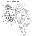
As shown in Fig 1B, Fig 2 and Fig 3, four supporting
springs 9, which are members elastic in the lengthwise direction
are firmly stuck to the fixed part 8 in the horizontal direction.
At the tips of the four supporting springs 9 is arranged a movable
part 10, which is supported by the supporting springs 9 to be
oscillatable in the directions of arrow C or D and of arrow
E or F.
In the movable part 10 the objective lens 3 is arranged
opposite the recordingmedium 4, and a raisingmirror (not shown)
is disposed underneath the objective lens 3, so that the laser
beam from the laser generating device be reflected by the raising
mirror to bring it into incidence on the objective lens 3. The
laser beam is narrowed down by the objective lens 3 to focus
on the recording face of the recording medium 4.
Underneath the movable part 10 is arranged a focusing
coil 11a and on a side of it is disposed a tracking coil 11b
so that the movable part 10 be slightly shifted in the direction
of arrow C or D to control focusing by electrifying the focusing
coil 11a and be slightly shifted in the direction of arrow E
or F to control tracking by electrifying the tracking coil 11b.
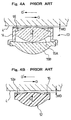
As shown in Figs 4, a single lens 12 (see Fig 4B) made
of glass, transparent plastic or the like or a paired lens 13
(see Fig 4A) is used as the objective lens 3. The paired lens
13 is configured of two lenses 15A and 15B built into a mirror
tube 14 which is formed of metals, plastic or the like. The
tube 14 may be structurally integrated with the lens 15A or
the lens 15B.
Usually an optical disc recording/reproducing system
requires a beam spot size which takes into account the recording
density, system margin and tolerance for manufacturing errors.
The beam spot size of an objective lens can be represented by
the following formula:
Beam spot diameter ∝ wavelength/NA (NA: aperture number
of objective lens)
When the density of an optical disc is increased with
its size unchanged, the required beam spot size becomes smaller
because the recording mark becomes smaller. Therefore,
according to Formula 1, in order to reduce the beam spot size,
it is required either to shorten the wavelength or to enlarge
the NA or both.
Then, the NA can be represented by the following formula :
NA = Effective radius of objective lens/focal distance
of objective lens ... Formula 2
According to Formula 2, in order to achieve a large NA,
either the effective radius of the objective lens can be
increased or the focal distance of the objective lens can be
reduced, but if the effective radius is increased, the diameter
of the objective lens and other optical components will
inevitably increase, resulting in an increased size of the
optical pickup device and ensuing disadvantages including a
higher price, higher power consumption and exceeding the size
limitation of the computer or other applications due to an
increased weight; therefore it is more advantageous to reduce
the focal distance.
Or if a short working wavelength is determined to reduce
the spot size, the refractive index of the material of the
objective lens will become high, resulting in a reduced focal
distance.
Therefore, usually in a high density optical disc
recording/reproducing apparatus, the wavelength is shortened,
the NA is increased and the focal distance of the objective
lens is reduced.
Further, whereas the distance from the closest face of
the objective lens to the optical disc to the surface of the
optical disc is usually referred to as the WD (working distance),
this factor, though not completely proportional to the focal
distance of the lens, tends to become shorter with a decrease
in focal distance. Therefore, in a high density optical disc
reproducing apparatus, the WD tends to become shorter.
If an optical pickup device is to be further reduced
in size with the wavelength and the NA kept unchanged, especially
if an optical disc recording/reproducing system is to be made
thinner to mount it on a low profile product, such as a laptop
personal computer, the effective radius of the beam will have
to be reduced. As is evident from Formula 2, the focal distance
would become smaller at the rate of reduction of the effective
radius. Then, even though it is an optical disc
recording/reproducing system of the same recording density,
its focal distance will become shorter, and the WD will also
become shorter.
When recording or reproduction is to be done onto or
from an optical disc (recording medium) with an optical disc
recording/reproducing system, an actuator movable part and the
objective lens are subjected to focusing control and tracking
control according to a prescribed detection signal obtained
from the optical disc. If in this process there is a major
defect or the like in the optical disc under recording or
reproduction and the detection signal is heavily affected, servo
may go off, and the actuator movable part may abruptly shift
in a direction other than the prescribed and at a speed beyond
the prescribed. If then the system is a high density or small
and thin optical pickup device, the objective lens may hit
against the optical disc.
Even if there is no major defect in the optical disc,
if the vibration due to any geometrical deformation of or density
imbalance in the optical disc, the vibration due to the state
in which the apparatus is installed, or the impact or vibration
working from outside on the apparatus accelerates very
significantly, a similar phenomenon will arise.
If then the objective lens hits against the optical disc
turning at high speed, the objective lens may be damaged, or
the dust resulting from scratching the optical disc may stick
to the surface of the objective lens, which could cause trouble
to subsequent recording and/or reproduction.
As shown in Fig 2, Fig 3 and Figs 4, for the objective
lens 3 of the conventional optical disc recording/reproducing
apparatus 1, a ring-shaped buffer 16 is fitted with an adhesive
or otherwise to the face of the tube 14 opposite an optical
disc 4 (Fig 4A) or to the top face of the peripheral part 12a
of the objective lens 12. This prevents the optical disc 4
from coming into direct contact with the objective lens 3 or,
even if it does come into contact, the lens 12 or the lens 15A
constituting the objective lens 3 from being damaged or the
optical disc 4 from being scratched. The buffer 16 is shaped
in a ring because this shape facilitates fitting of the buffer
16 and makes it possible to secure an appropriate WD by minimizing
the error of fitting height (e.g. see the Japanese Patent
Application Laid-Open No. 5-144041).
In recent years, with a view to further increasing the
density of data to be recorded, a large capacity optical disc
reproducing apparatus of the next generation has come to be
studied, which is to use a blue laser beam of 405 nm in laser
wavelength and capable of recording high resolution video images
for two hours. The aperture number (NA) of an objective lens
using a blue laser beam has to be 0.7 or more, and along with
that the WD should be extremely shortened, to 0.51 mm or less
(e.g. 0.24 mm).
When the optical disc is turned at high speed to record
or read out data, the air adjoining the optical disc will be
taken around along with the rotation of the optical disc, and
a high speed air flow will arise in the narrow gap (WD) between
the optical disc and the objective lens, and the pressure drops
in this gap.
In this case of the prior art in which the ring-shaped
protecting member is arranged on the face of the objective lens
opposite the optical disc, if the gap (WD) between the objective
lens and the optical disc is narrow, the flow rate of air in
the narrow part will rise with the rotation of the optical disc,
resulting in a reduced pressure, which may cause the objective
lens to be sucked toward the optical disc (in the direction
of arrows H in Figs 4). In the large capacity optical disc
reproducing apparatus of the next generation, which is to use
a blue laser beam of 405 nm in wavelength, the WD will be short,
and the pressure drop will tend to be greater.
This would give rise to problems such as the obstruction
of appropriate focusing control and tracking control, an
increased frequency of contact with the optical disc to invite
damaging of the objective lens, damaging of the optical disc
by scratching of its surface or sticking of the dust of scratching
to the objective lens to invite functional trouble.
[Disclosure of the Invention]
As one of the problems to be solved by the present
invention, the above-described problem can be cited as an
example.
In order to solve the problem noted above, according
to one aspect of the invention, an optical disc reproducing
apparatus for reading out data optically recorded on the optical
disc via an objective lens provided with a ring-shaped lens
protecting part arranged opposite an optical disc and protruding
toward the optical disc, the lens protecting part is
characterized in that at least one concave or concaves for
establishing communication between the inside and the outside
of the ring is or are formed therein.
In order to solve the problem noted above, according
to another aspect of the invention, an obj ective lens for reading
out data optically recorded on an optical disc, the objective
lens being provided with a lens protecting part arranged
opposite the optical disc, is characterized in that the lens
protecting part is formed in a ring-shape protruding toward
the optical disc and at least one concave or concaves for
establishing communication between the inside and the outside
of the ring is or are formed therein.
The concave or concaves of the lens protecting part is
or are characterized by being disposed in a direction tangential
to the optical disc and orthogonal to the tracking direction
so as to bisect the face of the lens protecting part opposite
the optical disc.
In order to solve the problem noted above, according
to still another aspect of the invention, a lens protecting
part is characterized in that it is disposed on a face of an
objective lens, for optically reading out data recorded on an
optical disc, opposite the optical disc, is formed in a ring
shape protruding toward the optical disc, and has at least one
concave or concaves for establishing communication between the
inside and the outside of the ring being formed therein.
The concave or concaves of the lens protecting part is
or are characterized by being disposed in a direction parallel
to a tangent to the optical disc and orthogonal to the tracking
direction so as to bisect the face of the lens protecting part
opposite the optical disc.
In order to solve the problem noted above, according
to still another aspect of the invention, an optical disc
reproducing method for reading out data optically recorded on
an optical disc via an obj ective lens provided with a ring-shaped
lens protecting part opposite the optical disc and protruding
toward the optical disc is characterized in that at least one
concave or concaves for establishing communication between the
inside and the outside of the ring is or are formed in the lens
protecting part, and the pressures inside and outside the ring
are equalized to prevent the optical disc and the objective
lens from coming into contact with each other.
[Brief Description of the Drawings]
Fig 1A is a plan of the essential part showing a schematic
configuration of an optical disc reproducing apparatus;
Fig 1B is a perspective view showing a schematic
configuration of an actuator;
Fig 2 is a perspective view of the actuator;
Fig 3 is an exploded perspective view of the essential
part of the actuator;
Fig 4A is a vertical section of an objective lens and
a lens protecting part configured of two lenses built into a
tube;
Fig 4B is a vertical section of a single objective lens
and a lens protecting part;
Fig 5, pertaining to a first embodiment for carrying
out the invention, is a perspective view of an actuator;
Fig 6, pertaining to the first embodiment for carrying
out the invention, is a vertical section of an objective lens
configured of double lenses and a lens protecting part;
Fig 7, pertaining to the first embodiment of the
invention, is a perspective view of an obj ective lens configured
of double lenses and a lens protecting part;
Fig 8, pertaining to the first embodiment of the
invention, is a plan of the essential part showing a schematic
configuration of an optical disc reproducing apparatus;
Fig 9, pertaining to a second embodiment for carrying
out the invention, is a perspective view of a single objective
lens and a lens protecting part;
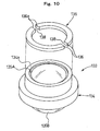
Fig 10, pertaining to a third embodiment for carrying
out the invention, is a perspective view of an objective lens
configured of double lenses and a pair of circular lens
protecting parts;
Fig 11, pertaining to a fourth embodiment for carrying
out the invention, is a perspective view of a single objective
lens and a pair of circular lens protecting parts;
Fig 12A pertains to a fifth embodiment for carrying out
the invention, showing a perspective view of a lens protecting
part formed integrally with a single objective lens;
Fig 12B pertains to a fifth embodiment for carrying out
the invention, showing a perspective view showing a vertical
section, of a lens protecting part formed integrally with a
single objective lens;
Fig 13A pertains to a sixth embodiment for carrying out
the invention, showing a perspective view, and (B) showing a
vertical section, of a lens protecting part formed integrally
with a tube;
Fig 13B pertains to a sixth embodiment for carrying out
the invention, showing a vertical section, of a lens protecting
part formed integrally with a tube;
Fig 14, pertaining to a seventh embodiment for carrying
out the invention, is a perspective view of a lens protecting
part in which a concave is formed in one position;
Fig 15, pertaining to an eighth embodiment for carrying
out the invention, is a perspective view of a lens protecting
part in which one position is cut off to form a C shape;
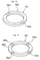
Fig 16, pertaining to a ninth embodiment for carrying
out the invention, is a perspective view of a lens protecting
part in which substantially V-shaped concaves are formed in
two positions;
Fig 17, pertaining to a 10th embodiment for carrying
out the invention, is a perspective view of a lens protecting
part in which concaves are formed in four positions; and
Fig 18, pertaining to an 11th embodiment for carrying
out the invention, is a perspective view of a lens protecting
part in which paired concaves are formed in a total of four
positions along the circumference.
[Best Mode for Carrying Out the Invention]
Embodiments for carrying out the present invention will
be described in detail below with reference to drawings.
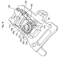
As shown in Fig 5 and Fig 8, an optical disc reproducing
apparatus 100 pertaining to the first embodiment for carrying
out the invention causes a blue laser beam of 405 nm in wavelength
emitted from a laser generating device (not shown), such as
a semiconductor laser oscillator, to be converged by an
obj ective lens 103 disposed in a movable part 110, and irradiates
an optical disc recording medium 104 to record data or to read
out recorded data.
As shown in Fig 8, substantially at the center of the
base (not shown) of the optical disc reproducing apparatus 100,
there is disposed a spindle motor (not shown). The optical
disc recording medium 104 is fitted to a disk table (not shown)
fixed to the rotation shaft of the spindle motor, and enabled
to turn in the direction of arrow G (or the direction of G')
at a prescribed rotating speed.
Two guide shafts 106 are arranged on the base in parallel
to the radial direction of the optical disc recording medium
104. A pickup body 102 is slidably disposed on the two guide
shafts 106 and, guided by the guide shafts 106, can shift in
the radial direction of the optical disc recording medium 104
which is in the form of an optical disc (direction of arrow
A or B).
As shown in Fig 5 and Fig 8, a yoke 105 is fixed to the
pickup body 102, and to the yoke 105 is fixed a fixed part 108,
which is shifted in the direction of arrow A or B together with
the pickup body 102. To the fixed part 108 are firmly stuck
four supporting springs 109 in the horizontal direction. At
the tips of the four supporting springs 109 is arranged the
movable part 110, which are supported by the supporting springs
109 to be oscillatable in the tracking direction (the direction
of arrow A or B) and the focusing direction (the direction of
toward or away from the optical disc recording medium 104).
On the movable part 110, there is arranged the obj ective
lens 103 opposite the recording face of the optical disc
recording medium 104; underneath the objective lens 103 is
arranged a raising mirror (not shown), and a laser beam, which
may be blue for instance, emitted from a laser generating device
(not shown) is reflected by the raising mirror and comes incident
on the objective lens 103. The luminous flux of the laser beam
is narrowed down by the objective lens 103 to focus on the
recording face of the optical disc recording medium 104.
At the time of recording data, the recording face of
the optical disc recording medium 104 is irradiated with the
laser beam, and the data are recorded as pits. Data recorded
thereon are read out by irradiating a pit formed in the recording
face of the optical disc recording medium 104 with the laser
beam, detecting the reflected beam from the pit with a
photosensor (not shown) via the objective lens 103 and the
raising mirror, and converting it into electric signals.
As shown in Fig 5, a focusing coil 111a is arranged
underneath the movable part 110, and a tracking coil 111b is
arranged beside it. Focusing control is accomplished by
electrifying the focusing coil 111a as required, slightly
shifting the movable part 110 in the direction toward or away
from the optical disc recording medium 104, and accurately
focusing on a pit formed in the optical disc recording medium
104. Similarly, tracking control is accomplished by
electrifying the tracking coil 111b, slightly shifting the
movable part 110 in the radial direction of the optical disc
recording medium 104, and irradiating the center of the pit
in its widthwise direction with the blue laser beam.
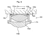
As shown in Fig 6 and Fig 7, the objective lens 103 is
configured of two lenses 115A and 115B fabricated of transparent
glass, plastic or the like into a mirror tube 114 formed of
metals, plastic or the like.
To the top face 114a of the tube 114 (the face opposite
the optical disc recording medium 104) is firmly stuck a
protecting part 116 with an adhesive or otherwise. The tube
114 may be structurally integrated with the lens 115A or the
lens 115B.
The protecting part 116 is a member formed in a
substantially ring shape of, for instance, Teflon (registered
trademark), nylon, elastomer, unwoven cloth or the like, and
has concaves 116a formed in two positions in the diametric
direction in the face opposite the optical disc recordingmedium
104.
Therefore, the inside and the outside of the ring-shaped
protecting part 116 communicate with each other via the concaves
116a.
As shown in Fig 8, the concaves 116a are so arranged
as to be tangential to the optical disc recording medium 104
and orthogonal to the tracking direction.
As shown in Fig 6, the top face 116b of the protecting
part 116 is at least as high as or higher than the top face
of the lens 115A, and is intended to protect the objective lens
103.
The gap (WD) between the objective lens 103 using a blue
laser beam of 405 nm in wavelength, for instance, and the optical
disc recording medium 104 is very short, only about 0.24 mm.
Should the protecting part 116 and the optical disc
recording medium 104 come into contact with each other, the
optical disc recording medium 104 and the lens 115A could be
prevented from being damaged because the protecting part 116
is small in friction coefficient and formed of a soft material.
When the optical disc recording medium 104 is turned
to record data onto or reading data recorded on the optical
disc recording medium 104, the air surrounding the optical disc
recording medium 104 is taken around along with the rotation.
This causes a high speed air flow to occur between the optical
disc recording medium 104 and the objective lens 103 with only
a very short WD in-between, and a negative pressure is generated.
However, as the ring-shaped protecting part 116 is
provided with the concaves 116a in a direction tangential to
the optical disc recording medium 104 and orthogonal to the
tracking direction and communicates with the outside, no
significant increase in flow rate occurs in the narrow gap,
the negative pressure is kept to the minimum, and the pressures
in and out of the protecting part 116 become substantially the
same.
Therefore, the objective lens 103 is not sucked toward
the optical disc recording medium 104, and the objective lens
103 and the optical disc recording medium 104 can be prevented
from coming into contact with each other.
Also, the impact of the negative pressure that is
generated on focusing control and tracking control can be
minimized to make possible highly accurate data recording and
reproduction.
To add, the formation of the concaves 116a in a direction
tangential to the optical disc recording medium 104 and
orthogonal to the tracking direction is intended to enable the
air flow taken around along with the rotation of the optical
disc recording medium 104 to readily flow from the outside into
the inside of, and from the inside to the outside of, the
ring-shaped protecting part 116 via the concaves 116a and
thereby to equalize the pressures in and out of the ring-shaped
protecting part 116.
Next will be described reproduction from the optical
disc pertaining to the second embodiment for carrying out the
invention.
Incidentally in the following description, since other
parts than the objective lens are the same as in the optical
disc reproducing apparatus 100 in the first embodiment for
implementation described with reference to Fig 5 and Fig 8,
the description of the other parts than the objective lens will
be dispensed with.
As shown in Fig 9, an objective lens 123 in the second
embodiment for implementation is configured as a single lens
formed of glass, transparent plastic or the like. Thus the
central part 122a of an obj ective lens 122 is formed in a curved
shape having a prescribed radius of curvature so as to serve
as a lens. A ring-shaped flat part 122b is formed in the
circumferential part. To the ring-shaped flat part 122b is
firmly stuck a ring-shaped protecting part 126 with an adhesive
or otherwise.
The protecting part 126 is a member formed in a
substantially ring shape of, for instance, Teflon (registered
trademark), nylon, elastomer, unwoven cloth or the like, and
has concaves 126a formed in two positions in the diametric
direction in the face opposite the optical disc recording medium
104. Therefore, the top face 126b of the ring-shapedprotecting
part 126 is bisected by the concaves 126a, and the inside and
the outside of the ring communicate with each other via the
concaves 126a. The concaves 126a are arranged in a movable
part (not shown) in a direction tangential to the optical disc
recording medium 104 and orthogonal to the tracking direction.
As shown in Figs 10, an objective lens 133 in the third
embodiment for implementation has a configuration in which two
lenses 135A and 135B formed of glass, transparent plastic or
the like are built into a tube 134 formed of ceramic, aluminum,
magnesium, bronze, zinc, nickel, an alloy thereof or the like.
To a face 134a of the tube 134 opposite the optical disc recording
medium 104 are firmly stuck with an adhesive or otherwise a
pair of circular protecting parts 136 to constitute a
substantial circle. The mutually opposite end faces 136a of
the pair of protecting parts 136 are so arranged as to be away
from each other, and two gaps 138 are formed between the end
faces 136a. The inside and the outside of the pair of protecting
parts 136 arranged in a substantially circular shape communicate
with each other via the two gaps 138. The gaps 138 are arranged
in a movable part in a direction tangential to the optical disc
recording medium 104 and orthogonal to the tracking direction.
As shown in Fig 11, an objective lens 143 in the fourth
embodiment for implementation is configured of a single lens
formed of glass, transparent plastic or the like.
Thus, the central part 143a of an objective lens 143
is formed in a curved shape having a prescribed radius of
curvature so as to serve as a lens. In the circumferential
part is formed a ring-shaped flat part 143b. To the ring-shaped
flat part 143b are firmly stuck a pair of circular protecting
parts 146 with an adhesive or otherwise to constitute a
substantial circle. The mutually opposite end faces 146a of
the pair of protecting parts 146 are so arranged as to be away
from each other, and two gaps 148 are formed between them. The
inside and the outside of the pair of protecting parts 146
arranged in a substantially circular shape communicate with
each other via the gaps 148. The gaps 148 are arranged in a
movable part in a direction tangential to the optical disc
recording medium 104 and orthogonal to the tracking direction.
As shown in Figs 12, an objective lens 153 in the fifth
embodiment for implementation is configured of a single lens
formed of transparent plastic or the like.
Thus, the central part of the obj ective lens 153 is formed
in a curved shape having a prescribed radius of curvature, and
a lens part 153a is formed there. The circumferential part
of the lens part 153a is raised in a ring shape to the same
height as the lens part 153a, and on the top face is formed
a ring-shaped flat part 153b. In the ring-shaped flat part
153b, substantially U-shaped concaves 153c are formed in two
positions in the diametric direction. The concaves 153c are
arranged in a movable part in a direction parallel to a tangent
to the optical disc recording medium 104 and orthogonal to the
tracking direction. In this embodiment for implementation,
the obj ective lens and the protecting part are integrally molded
of the same material, and the ring-shaped flat part 153b serves
as the protecting part. Further, since the objective lens 153
in this embodiment for implementation permits mass production
by injection molding or otherwise, the objective lens 153 can
be fabricated inexpensively.
As shown in Figs 13, an objective lens 163 in the sixth
embodiment for implementation has a configuration in which two
lenses 165A and 165B formed of glass, transparent plastic or
the like are built into a tube 164 formed of ceramic, aluminum,
magnesium, bronze, zinc, nickel, an alloy thereof or the like.
A face 164a of the tube 164 opposite the optical disc recording
medium 104 (the top face) is set to be as high as the lens 165A,
and in the top face 164a are formed substantially U-shaped
concaves 164b in two positions in the diametric direction. The
concaves 164b are arranged in a movable part in a direction
parallel to a tangent to the optical disc recording medium 104
and orthogonal to the tracking direction.
In this embodiment for implementation, a protecting part
is integrally formed with the top face 164a of the tube 164
of the objective lens 163, and the top face 164a of the tube
164 serves as the protecting part.
As shown in Fig 14, a protecting part 176 in the seventh
embodiment for implementation is a member formed in a
substantially ring shape of, for instance, Teflon (registered
trademark), nylon, elastomer, unwoven cloth or the like, and
in part of the surface 176b (the face opposite the optical disc
recording medium 104) isformedasubstantiallyU-shapedconcave
176a in one position, via which the inside and the outside of
the ring-shaped protecting part 176 communicate with each other.
The protecting part 176, like the protecting part 116 or 126
shown in Fig 7 or Fig 9, respectively, is firmly stuck to the
tube or the circumferential part of the single lens with an
adhesive or otherwise.
As shown in Fig 15, a protecting part 186 in the eighth
embodiment for implementation is formed in a substantially C
shape having a gap 18 6a provided in one position of, for instance,
Teflon (registered trademark), nylon, elastomer, unwoven cloth
or the like. Communication is established by the gap 186a
between the inside and the outside of the protecting part 186.
The protecting part 186, like the protecting part 116 or 126
shown in Fig 7 or Fig 9, respectively, is firmly stuck to the
top face of the tube or the circumferential flat part of the
single lens with an adhesive or otherwise.
As shown in Fig 16, a protecting part 196 in the ninth
embodiment for implementation is a member formed in a
substantially ring shape of, for instance, Teflon (registered
trademark), nylon, elastomer, unwoven cloth or the like, and
in the surface 196b (the face opposite the optical disc recording
medium 104) are formed substantially V-shaped concaves 196a
in two positions in the diametric direction to establish
communication between the inside and the outside of the
ring-shaped protecting part 196. The protecting part 196, like
the protecting part 116 or 126 shown in Fig 7 or Fig 9,
respectively, is firmly stuck to the tube or the circumferential
part of the single lens with an adhesive or otherwise.
Incidentally, the shape of concaves is not limited to
substantially U or V shapes, but can be any shape that can
effectively establish communication between the inside and the
outside of the protecting part.
As shown in Fig 17, a protecting part 206 in the 10th
embodiment for implementation is a member formed in a
substantially ring shape of, for instance, Teflon (registered
trademark), nylon, elastomer, unwoven cloth or the like, and
in the surface 206b (the face opposite the optical disc recording
medium 104) are formed substantially U-shaped concaves 206a
in four positions at 90° intervals to establish communication
between the inside and the outside of the ring-shaped protecting
part 206. The protecting part 206, like the protecting part
116 or 126 shown in Fig 7 or Fig 9, respectively, is firmly
stuck to the tube or the circumferential part of the single
lens with an adhesive or otherwise.
Incidentally the number of concaves is not limited to
two or four, but can be increased or decreased as appropriate
so as to effectively establish communication between the inside
and the outside of the protecting part.
As shown in Fig 18, a protecting part 216 in the 11th
embodiment for implementation is a member formed in a
substantially ring shape of, for instance, Teflon (registered
trademark), nylon, elastomer, unwoven cloth or the like, and
in the surface 216b (the face opposite the optical disc recording
medium 104) are formed pairs of substantially U-shaped concaves
216a in a total of four positions in the radial direction to
establish communication between the inside and the outside of
the ring-shaped protecting part 216. The protecting part 216,
like the protecting part 116 or 126 shown in Fig 7 or Fig 9,
respectively, is firmly stuck to the tube or the circumferential
part of the single lens with an adhesive or otherwise.
In the optical disc reproducing apparatus in each of
the embodiments for implementation, a ring-shaped lens
protecting part is provided on the surface of the objective
lens opposite the optical disc recording medium. In each lens
protecting part, to establish communication between the inside
and the outside of the ring, concaves are formed in a direction
parallel to a tangent to the optical disc recording medium and
orthogonal to the tracking direction.
For this reason, the pressure difference is extremely
small between the inside and the outside of the ring-shaped
lens protecting part. Therefore, the objective lens is not
sucked toward the optical disc recording medium by a drop in
pressure.
This enables the optical disc recording medium and the
lens protecting part to be prevented from coming into contact
with each other, and accordingly to avoid injuring of the
objective lens by the contact, damaging of the optical disc
recording medium by scratching of its surface or sticking of
the dust of scratching to the obj ective lens to invite functional
trouble.
Furthermore, as the impact on the focusing control and
tracking control of the objective lens can be completely
eliminated, proper focusing control and tracking control can
be readily accomplished, making possible highly reliable
recording and reading-out of data.
To sum up the contents hitherto stated, the optical disc
reproducing apparatus 100 optically records data onto or read
data recorded on the optical disc recording medium 104 via the
objective lens 103, 123, 133, 143, 153 or 163 provided with
the ring-shaped lens protecting part 116, 126, 136, 146, 153b,
164a, 176, 186, 196 or 206 disposed opposite and protruding
toward the optical disc recording medium 104. In this optical
disc reproducing apparatus 100, at least one concave or concaves
116a, 126a, 138, 148, 153c, 164b, 176a, 186a, 196a, 206a or
216a for establishing communication between the inside and the
outside of the ring is or are formed in the lens protecting
part 116, 126, 136, 146, 153b, 164a, 176, 186, 196, 206 or 216.
The objective lens 103, 123, 133, 143, 153 or 163 for
recording data onto or reading data optically recorded on the
optical disc recording medium 104 is provided with the lens
protecting part 116, 126, 136, 146, 153b, 164a, 176, 186, 196,
206 or 216 disposed opposite the optical disc recording medium
104. In the lens protecting part 116, 126, 136, 146, 153b,
164a, 176, 186, 196, 206 or 216, which is formed in a ring shape
protruding toward the optical disc recording medium 104, at
least one concave or concaves 116a, 126a, 138, 148, 153c, 164b,
176a, 186a, 196a, 206a or 216a for establishing communication
between the inside and the outside of the ring is or are formed.
The lens protecting part 116, 126, 136, 146, 153b, 164a,
176, 186, 196, 206 or 216 is disposed on the face of the objective
lens 103, 123, 133, 143, 153 or 163, which is for recording
data onto or reading data optically recorded on the optical
disc recording medium 104, opposite the optical disc recording
medium 104, is formed in a ring shape protruding toward the
optical disc recording medium 104, and has at least one concave
or concaves 116a, 126a, 138, 148, 153c, 164b, 176a, 186a, 196a,
206a or 216a formed therein to establish communication between
the inside and the outside of the ring.
By the optical disc reproducing method in each of the
embodiments for implementation, data are optically recorded
onto the optical disc recording medium 104 or data recorded
thereon are read out via the objective lens 103, 123, 133, 143,
153 or 163 provided with the ring-shaped lens protecting part
116, 126, 136, 146, 153b, 164a, 176, 186, 196, 206 or 216 disposed
opposite and protruding toward the optical disc recordingmedium
104, wherein at least one concave or concaves 116a, 126a, 138,
148, 153c, 164b, 176a, 186a, 196a, 206a or 216a for establishing
communication between the inside and the outside of the ring
is or are formed in the lens protecting part 116, 126, 136,
146, 153b, 164a, 176, 186, 196, 206 or 216 to equalize the
pressures inside and outside the ring, and the optical disc
recording medium 104 and the obj ective lens 103, 123, 133, 143,
153 or 163 are prevented from coming into contact with each
other.
To add, the optical disc reproducing apparatus, the
objective lens, the protecting member and the optical disc
reproducing method according to the invention are not limited
to the embodiments for implementation described above, but
permit modifications, improvements or other changes as
appropriate. For instance, although the lens protecting part
in some of the above-described embodiments for implementation
is supposed to be integrally molded with a ring-shaped member
formed of Teflon (registered trademark), nylon, elastomer,
unwoven cloth or the like or with the objective lens, it could
as well be formed by printing on or transferring onto the tube
or the circumferential flat part of the objective lens.
Also, the materials, shapes, dimensions, forms, numbers,
positions of arrangement and other factors of the optical disc,
lens protecting part, objective lens, concaves and the like,
examples of which are described in connection with the
above-described embodiments for implementation, are not
limited to what were stated above, but any other alternatives
can be used if they enable the present invention to be
implemented.
Further, the invention is not limited to the
above-described embodiments for implementation, which were
cited merely as examples. Any embodiment in which
substantially the same configuration as the technical ideas
stated in the claims for the invention and which would provide
similar effects and advantages is covered by the technical scope
of the invention.
All the disclosures in the Japanese Patent Application
(No. 2002-285243) filed on September 30, 2002, including its
specification, claims, drawings and abstract, are hereby
incorporated by reference into this application in its entirety.