JP3666632B2 - Aberration correction apparatus and optical pickup apparatus using the same - Google Patents
Aberration correction apparatus and optical pickup apparatus using the same Download PDFInfo
- Publication number
- JP3666632B2 JP3666632B2 JP35334998A JP35334998A JP3666632B2 JP 3666632 B2 JP3666632 B2 JP 3666632B2 JP 35334998 A JP35334998 A JP 35334998A JP 35334998 A JP35334998 A JP 35334998A JP 3666632 B2 JP3666632 B2 JP 3666632B2
- Authority
- JP
- Japan
- Prior art keywords
- optical
- optical axis
- light
- aberration correction
- aberration
- Prior art date
- Legal status (The legal status is an assumption and is not a legal conclusion. Google has not performed a legal analysis and makes no representation as to the accuracy of the status listed.)
- Expired - Fee Related
Links
Images


Classifications
-
- G—PHYSICS
- G11—INFORMATION STORAGE
- G11B—INFORMATION STORAGE BASED ON RELATIVE MOVEMENT BETWEEN RECORD CARRIER AND TRANSDUCER
- G11B7/00—Recording or reproducing by optical means, e.g. recording using a thermal beam of optical radiation by modifying optical properties or the physical structure, reproducing using an optical beam at lower power by sensing optical properties; Record carriers therefor
- G11B7/12—Heads, e.g. forming of the optical beam spot or modulation of the optical beam
- G11B7/135—Means for guiding the beam from the source to the record carrier or from the record carrier to the detector
- G11B7/1372—Lenses
- G11B7/1378—Separate aberration correction lenses; Cylindrical lenses to generate astigmatism; Beam expanders
-
- G—PHYSICS
- G11—INFORMATION STORAGE
- G11B—INFORMATION STORAGE BASED ON RELATIVE MOVEMENT BETWEEN RECORD CARRIER AND TRANSDUCER
- G11B7/00—Recording or reproducing by optical means, e.g. recording using a thermal beam of optical radiation by modifying optical properties or the physical structure, reproducing using an optical beam at lower power by sensing optical properties; Record carriers therefor
- G11B7/08—Disposition or mounting of heads or light sources relatively to record carriers
- G11B7/09—Disposition or mounting of heads or light sources relatively to record carriers with provision for moving the light beam or focus plane for the purpose of maintaining alignment of the light beam relative to the record carrier during transducing operation, e.g. to compensate for surface irregularities of the latter or for track following
- G11B7/095—Disposition or mounting of heads or light sources relatively to record carriers with provision for moving the light beam or focus plane for the purpose of maintaining alignment of the light beam relative to the record carrier during transducing operation, e.g. to compensate for surface irregularities of the latter or for track following specially adapted for discs, e.g. for compensation of eccentricity or wobble
- G11B7/0956—Disposition or mounting of heads or light sources relatively to record carriers with provision for moving the light beam or focus plane for the purpose of maintaining alignment of the light beam relative to the record carrier during transducing operation, e.g. to compensate for surface irregularities of the latter or for track following specially adapted for discs, e.g. for compensation of eccentricity or wobble to compensate for tilt, skew, warp or inclination of the disc, i.e. maintain the optical axis at right angles to the disc
-
- G—PHYSICS
- G11—INFORMATION STORAGE
- G11B—INFORMATION STORAGE BASED ON RELATIVE MOVEMENT BETWEEN RECORD CARRIER AND TRANSDUCER
- G11B7/00—Recording or reproducing by optical means, e.g. recording using a thermal beam of optical radiation by modifying optical properties or the physical structure, reproducing using an optical beam at lower power by sensing optical properties; Record carriers therefor
- G11B7/12—Heads, e.g. forming of the optical beam spot or modulation of the optical beam
- G11B7/135—Means for guiding the beam from the source to the record carrier or from the record carrier to the detector
- G11B7/1392—Means for controlling the beam wavefront, e.g. for correction of aberration
- G11B7/13925—Means for controlling the beam wavefront, e.g. for correction of aberration active, e.g. controlled by electrical or mechanical means
- G11B7/13927—Means for controlling the beam wavefront, e.g. for correction of aberration active, e.g. controlled by electrical or mechanical means during transducing, e.g. to correct for variation of the spherical aberration due to disc tilt or irregularities in the cover layer thickness
-
- G—PHYSICS
- G11—INFORMATION STORAGE
- G11B—INFORMATION STORAGE BASED ON RELATIVE MOVEMENT BETWEEN RECORD CARRIER AND TRANSDUCER
- G11B7/00—Recording or reproducing by optical means, e.g. recording using a thermal beam of optical radiation by modifying optical properties or the physical structure, reproducing using an optical beam at lower power by sensing optical properties; Record carriers therefor
- G11B7/12—Heads, e.g. forming of the optical beam spot or modulation of the optical beam
- G11B7/135—Means for guiding the beam from the source to the record carrier or from the record carrier to the detector
- G11B7/1372—Lenses
- G11B2007/13727—Compound lenses, i.e. two or more lenses co-operating to perform a function, e.g. compound objective lens including a solid immersion lens, positive and negative lenses either bonded together or with adjustable spacing
Landscapes
- Physics & Mathematics (AREA)
- Optics & Photonics (AREA)
- Optical Head (AREA)
- Optical Recording Or Reproduction (AREA)
- Lenses (AREA)
Description
【0001】
【発明の属する技術分野】
本発明は、光学式情報記録媒体である光ディスクから信号を読み出し/書込む光学式情報記録再生装置における光ピックアップ装置に関する。
【0002】
【従来の技術】
光ディスクへの記録密度を向上させる目的で、光ピックアップ装置の対物レンズの開口数を大きくすることが考えられる。例えば、0.45から0.6へ開口数を大きくする。このとき、所定の厚さの透明ディスク基板を透過して情報記録面から情報を記録するように取り決められた規格においては、その透明ディスク基板の傾きによってコマ収差が発生し、適切な光スポットを情報記録面に照射することができなくなる。特にこのコマ収差発生量は開口数が大きくなると顕著に増大するため、射出成形などによって成形した透明ディスク基板を用いて光ディスクを廉価に作製した場合には、光ディスクの反りによる傾きが大きくなり、コマ収差による悪影響を大きく受ける。
【0003】
このコマ収差の影響を低減するために、透明ディスク基板厚を薄くする。例えば、1.2mmから0.6mmへ基板厚を薄くする。こうすると、光ディスク表面の汚れ、傷などの影響を顕著に受けるようになってしまい、長期間の使用などによって光ディスク性能の劣化が生じると言う問題点がある。
また、光ディスクの傾き(スキュー)調整機構をピックアップ装置に取り付け、光ディスクの傾きに追従してピックアップ自体を傾けるチルト・サーボ機構が用いることが考えられるが、このような方法では可動部分の慣性重量が大きく応答速度が遅いことが懸念される。このために光ディスクの1回転中での傾き変動、特に時間軸方向(接線方向)の傾きにピックアップ自体の傾動が追従することができない。よって、接線方向傾きによるコマ収差の補正が開口数を大きくした対物レンズを用いたピックアップ装置において問題となる。
【0004】
【発明が解決しようとする課題】
コマ収差の補正を行なう方法として、特開平7−140381に示したような技術が知られている。図1に示すように、瞳上半径Rに対し、Rの4乗で変化するような凸面と同一形状の凹面を組み合せた2枚の補償板1及び2を光軸に直交する方向に相互に移動させることによってコマ収差の補正を行なっている。
【0005】
ここで、もし光ディスク5が接線方向に傾いている場合には、これによる接線方向の収差が発生する。対物レンズ4のような、比較的開口数の大きい凸レンズを用いる場合には、この収差は3次のいわゆるコマ収差が大きく、このほかに非点収差、高次の収差が加わる。この高次の収差は開口数が大きいほど顕著に現れる。
【0006】
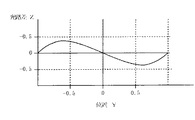
図2に示す(A)は、光ディスク5の透明ディスク基板が傾いた場合の収差による瞳内での光路長差の変化を示す。図では横軸は瞳上の半径位置、縦軸は発生する波面の位相差を光路長差として1波長を単位として表している。理想的な無収差状態ではこの光路長差は発生しない。光ビームが垂直に入射して周縁が光軸に対して対称であるからである。図2は対物レンズの開口数を0.85とし、光ディスクが水平から1度の角度で傾いた場合の数値を計算した結果である。この変化量は光ディスクの傾き量に伴って増減する。
【0007】
この収差は光ディスクの透明ディスク基板の傾きによって発生するものであり、図2に示す光路長差の曲線形状が左上がりとなっていることは、透明ディスク基板が傾くことによる波面、すなわち光軸からの光の進行方向の偏向を表している。
例えば光源から対物レンズに到る光路中に、この波面収差をそのままの形(図2(A))の逆波面収差の上記補償板を挿入して補正することは、光ディスク上で回折限界スポットを結ぶための波面を構成することに加え補償板通過後の光の進行方向に偏向を与えることとなり、図1に示すように、この偏向は光ビームが対物レンズへ斜め方向から入射するような悪効果を生み出し、結像性能の低下をきたす。さらに、接線方向傾きの補正に用いる場合には、一般的に光ピックアップでは接線方向に照射位置を調整する手段を持たないので、この偏向が照射位置の変移を生み出し、この変移が接線方向のジッタとなる。また、この周辺部での必要な収差補正量が大きいため、補正量に比例して厳しくなる位置変移による補正誤差も大きくなり、大きな開口数では実現が難しくなる。
【0008】
すなわち、この従来方法によると、挿入された補償板の移動によって光軸が偏向し、光ディスク上に照射されるスポットの中心位置が変移する。この照射光軸の偏向は、特に、接線方向の補正を行なうにあたって時間変動ノイズ(ジッタ)として作用し、接線方向の傾き補正を良好に行なえないと言う問題点があった。本発明は、上述した点に鑑みなされたものであり、従来のコマ収差の補正にあたって補償板の移動に起因する照射光軸の偏向を防止して時間変動ノイズ成分を良好に除去できる光ピックアップ装置を提供することを目的とする。
【0009】
【課題を解決するための手段】
本発明の収差補正装置は、光ディスクに光ビームを照射する光ピックアップ装置の光源から光ディスクに到る光路中に配置される収差補正装置であって、
離間して対向する互いに相補的な曲面を有する一対の光透過基板からなり、前記光透過基板の少なくとも一方は前記光路の光軸に垂直方向に移動自在に保持され、
前記曲面は、次式
【数4】
z = (ax) 6 −(bx) 4 +Cx 2 +Dx
(式中、zは光軸に平行な方向における高さ、xは光軸を中心とした半径を示す)を満たす形状であり、
前記数式における各係数は、前記光ディスクの透明板によって透過光ビームに与えられるコマ収差を最小とすべく、前記一対の光透過基板を透過する光ビームの光路長が前記光透過基板の移動によって変化することにより透過光ビームに位相差を与えつつ該位相差が該光ビームの進行方向を維持するように決定されている、ことを特徴とする。
【0010】
本発明の収差補正装置においては、前記曲面は、前記光ディスクの少なくとも半径又は接線の方向に関して対称であることを特徴とする。
本発明の収差補正装置においては、前記曲面は、次式
【0011】
【数5】
z=(ax)4−(bx)2
(式中、2a2=bである)を満たす形状であることを特徴とする。
本発明の収差補正装置においては、前記光透過基板の一方の表面形状は光軸周りで凸面でありかつ有効径内最外部における面法線が光軸に対して平行であり、他方の光透過基板は表面形状が光軸周りで凹面でありかつ有効径内最外部における面法線が光軸に対して平行であるように構成されることを特徴とする。
【0012】
本発明の収差補正装置においては、前記光透過基板の一方の表面形状は光軸周りで凸面でありかつ有効径内の外側において凹部が形成されており該凹部底部における面法線が光軸に対して平行であり、他方の光透過基板は表面形状が光軸周りで凹面でありかつ有効径内の外側において凸部が形成されており該凸部頂部における面法線が光軸に対して平行であるように構成されることを特徴とする。
【0013】
本発明の収差補正装置においては、前記光透過基板の一方の形状は光軸を含む平面を対称面とし、対称面を中心とする凸面であり、かつ、有効径内最外部における面法線が光軸に対して平行であり、他方の光透過基板は前記対称面を中心とする凹面であり、かつ、有効径内最外部における面法線が光軸に対して平行であることを特徴とする。
【0014】
本発明の収差補正装置においては、前記光透過基板の一方の形状は光軸を含む平面を対称面とし、対称面を中心とする凸面であり、かつ、有効径内外部において凹部が形成されており、該凹部底面の面法線が光軸に対して平行であり、他方の光透過基板は前記対称面を中心とする凹面であり、かつ、有効径内外部において凸部が形成されており、該凸部底面の面法線が光軸に対して平行であることを特徴とする。
【0015】
本発明の収差補正装置においては、前記光透過基板の少なくとも一方は前記光軸上の1点を中心とした円筒面内において駆動されることを特徴とする。
本発明の収差補正装置においては、前記光透過基板の少なくとも一方は前記光軸上の1点を中心とした球面内において駆動されることを特徴とする。
本発明の光ピックアップ装置は、光ビームを射出する光源、光ビームを光ディスクの情報記録面上に向け集光する対物レンズ、該光ビームを前記対物レンズに導く照射光学系、並びに、光検出手段を含み前記対物レンズを介して前記情報記録面からの反射光を前記光検出手段へ導く検出光学系、を備える、光ディスクから信号を読み出し及び/又は書込む光ピックアップ装置であって、
前記光ディスクの少なくとも半径又は接線の方向に関する傾きを検出する傾き検出手段と、
前記照射光学系に配置され、離間して対向する互いに相補的な曲面を有する一対の光透過基板からなり、前記光透過基板の少なくとも一方は前記曲面の光軸が前記光路の光軸に略平行にかつ前記光路の光軸に垂直方向に移動自在に保持され、前記曲面は、次式
【数6】
z = (ax) 6 −(bx) 4 +Cx 2 +Dx
(式中、zは光軸に平行な方向における高さ、xは光軸を中心とした半径を示す)を満たす非球面であり、前記数式における各係数は、前記光透過基板の移動によって前記一対の光透過基板を透過する光ビームの光路長を変化させて透過光ビームに位相差を与えつつ該位相差が該光ビームの進行方向を維持するように決定されている、収差補正装置と、
前記傾き検出手段からの前記光ディスクの傾き量に対応する出力に応じて、前記光透過基板を前記光路の光軸に垂直方向に移動せしめ、前記光ディスクの透明板によって透過光ビームに与えられる少なくとも半径又は接線方向のコマ収差を最小とする収差補正駆動手段と、を有することを特徴とする。
【0016】
本発明の光ピックアップ装置においては、前記光透過基板の少なくとも一方は、前記光軸と交差する前記光ディスクの半径方向へ伸長する回転軸を中心とした円筒面内において駆動されることを特徴とする。
本発明の光ピックアップ装置においては、前記光透過基板の少なくとも一方は、前記光軸上の1点を中心とした球面内において駆動されることを特徴とする。
【0017】
本発明の光ピックアップ装置における収差補正装置によれば、照射光軸方向に部分的に厚さが異なる2枚の光透過基板を略平行にしてそれらの光軸が照射光軸にほぼ一致するように配置し、この光透過基板の一方を照射光軸にほぼ垂直に移動せしめることによって、透過光の光路すなわち光透過基板の合計厚さを部分的に可変できるようにする。これによって、透過光ビームに所定の位相差分布を与えて、少ない補正量で波面補正を高速に行なえる。さらに、透過光の偏向による光スポットの変移を起こさずに収差の補正ができ、時間軸変動ノイズ成分を良好に除去できる。このように、本発明による光ピックアップの装置においては、光透過基板の移動により透過光ビームの部分的光路長を変えて光軸の偏向を抑制又は除去して補償板の移動に起因する照射光軸の偏向を防止し、照射光スポットの変移を起さない。
【0018】
【発明の実施の形態】
以下、本発明の実施例を図面を参照しつつ説明する。
図3に示す第1の実施例の収差補正装置100は、光ディスクから信号を読み出し及び/又は書込む光ピックアップ装置の例えば半導体レーザから光ディスク5に到る光路、あるいは光ディスク5から光検出器に到る光路中に配置され、例えばコリメータレンズと対物レンズの間に配置される。収差補正装置100は第1補正板101及び第2補正板102からなる。第1補正板101及び第2補正板102は部分的に厚さが異なるガラス板すなわち光透過基板であり、それぞれの平坦面がピックアップ光軸に対して垂直になるように配置されている。このうち第2補正板102は光軸に垂直な方向、例えば光ディスクの接線方向又は、及び半径方向に移動制御可能に支持されている。第2補正板102の移動により、半径方向のコマ収差のみの補正でも、接線方向のコマ収差のみの補正でも、半径方向と接線方向の両方のコマ収差の補正も可能となる。
【0019】
尚、光ビームは何度も屈折されたり反射されたりして光ディスクに導かれるため、補正板が配置される箇所の光ビームの光軸は、光ディスク面に垂直とは限らない。そのため、補正板は光ディスクの半径方向や接線方向と平行な方向に移動するものに限られるものではなく、光ディスク面上に照射される光ビームの光ディスク面上における接線方向や半径方向に対応する方向に移動する。
【0020】
第1補正板101及び第2補正板102は、離間して対向する互いに相補的な非球面である曲面101a及び102aをそれぞれ有する。第1及び第2補正板101,102の対向する曲面101a及び102aの反対側は、互いに平行で平坦な面101b及び102bである。第1及び第2補正板101,102の少なくとも一方は曲面の光軸が光ビームの光路の光軸に略平行にかつ垂直方向に移動自在に保持されていればよい。また、接線方向又は半径方向の一方の方向にのみ関係するコマ収差を補正をするものであれば、補正板の曲面は光軸を含む平面を対称面とする面対称な非球面で形成される。さらに、補正板の曲面が光軸を中心とする軸対称な非球面の場合は、接線方向と半径方向の両方のコマ収差を補正することができる。
【0021】
なお、接線方向又は半径方向の一方の方向のコマ収差を補正する補正板については、光軸を含む平面で、かつ、光ディスク面上に照射される光ビームの光ディスク面上における接線方向又は半径方向に対応する方向に平行な平面を、対称面という。
また、接線方向と半径方向の両方のコマ収差を補正する補正板については、光軸に平行な軸を対称軸とする。
【0022】
次に、第1及び第2補正板の曲面101a及び102aの面形状について説明する。光ピックアップの対物レンズを含む光学系においては、所定値の厚さを持つ透明ディスク基板を通して信号の記録再生を行なう。よって、透明ディスク基板に傾きが存在しない場合、すなわち、光軸に対して垂直に透明ディスク基板が配置された場合に光ディスク記録面上に回折限界スポットを結ぶように光学系が設計されている。
【0023】
本実施例においては、基板に傾きが存在する場合に発生する波面収差をそのままの形(図2)での逆波面収差を発生させる上記従来の補償板を光路中に挿入して補正するのではなく、光の進行方向の偏向を減らした波面収差を付与した曲面を有する補正板を用いる。一般に、レンズなどの光学素子の入射瞳径に対する収差の関係において、コマ収差は入射瞳径に大きく依存している。つまり入射瞳開口数が大きくなるとコマ収差も大きくなる。よって、収差補正装置によってディスク基板のコマ収差の逆のコマ収差を付与して当該コマ収差を相殺するに加えて、光学素子の近軸から外周へ向け光路長差を減ずるように変化させることにより、光軸の偏向を抑制することができる。
【0024】
そこで、この曲面101a及び102aは、光ディスクの透明基板を透過する光ビームに与えられる少なくとも接線方向のコマ収差を最小とすべく、透過光ビームの光路長が第1及び第2補正板の少なくとも一方の移動によって変化することにより透過光ビームに位相差を与えつつ該位相差が該光ビームの進行方向を維持するように、形成されている。
【0025】
すなわち、本発明において補正すべき波面の位相差形状は、図4に示すように、図4(A)(図2(A)に対応)の収差のある波面から移動分を除去した図4(B)に示すような位相差形状である。
図5,図6及び図7は、図3に示す第1の実施例で用いる第1及び第2補正板の曲面101a及び102aの面形状を示す。
【0026】
図5は、直交座標系でとった第1補正板101の半径方向の厚さを示す断面図である。図6はその等高線図である。図5及び図6に示すように、第1補正板101の曲面は光軸Oから対称に、最外周部P側に行くに従って薄くなっていて、しかも中央部Oだけでなく最外周部Pにおける厚さの変化率が0となるような形状になっている。すなわち、第1補正板101の断面は中央部Oの頂部及び最外周部Pの環状領域では面法線の方向が光軸方向と平行となるように形成されている。
【0027】
図7に示す第2補正板102も直交座標系でとった半径方向の厚さを表したものである。図7に示すように、その曲面は光軸Oから対称に、外側に行くに従って厚くなっていて、しかも最外周部Pにおける厚さの変化率が0となるような形状になっている。すなわち、第2補正板102の断面は中央部Oの陥没部及び最外周部Pの隆起環状領域では面法線の方向が光軸方向と平行となるように形成されている。この第2補正板102の曲面は図5及び図6に示す第1補正板101の曲面と相補的な関係で形成されるので、曲面側を重ねると平行平板となる。いずれも曲面は、光ディスクの少なくとも半径又は接線の方向に関して対称である。
【0028】
収差補正装置は、この二つの第1及び第2補正板101,102がそれらの光軸を共通として、照射光軸に一致させて、それぞれが接触しないように離間させて重ねて配置され、さらに少なくとも一方例えば第1補正板101を所定距離だけ光軸に垂直に移動自在にして構成される。
次に、第1の実施例の第1及び第2補正板の曲面101a及び102aの面形状をの設計例を説明する。まず、光ディスクの傾きによる収差の代表的な光軸からの距離の3次関数に比例して位相差(図4(A))が発生する場合を考える。この位相差から変移分を除いた光路長差(図4(B))を表すOPD0は光軸からの距離をxとして、
【0029】
【数7】
OPD0(x,y)=αx3−αx
と表すことができる。
いま、求めようとする第1補正板101の第2補正板に面する側の曲面101aの凸面形状が
【0030】
【数8】
z1=(ax)4−(bx)2
という面形状であるとする。ここで、定数aの値は後ほど特定する。
第2補正板102の第1補正板101に面する側の凸面形状も、第1補正板101と同じ相補形状で、
【0031】
【数9】
z2=(ax)4−(bx)2
である。第1補正板101と第2補正板102の間隔が十分近く、aが小さい値であれば、この2枚を透過した平行光の光路差OPDは
【0032】
【数10】
OPD(x,y)=z2(x)−z1(x)=0
となり、この2枚を通過したことによる波面位相差分布の変化はない。
次に、第2補正板102をx方向にΔxだけ動かした場合の位相差を考える。このときの光路差は
【0033】
【数11】
OPD(x;y+Δx,y)=z1(x)−z2(x+Δx)
=4a4Δxx3−2b2Δxx+6a4Δx2x2−b2Δx2+4a4Δx3x+a4Δx4
ここで、Δxの2乗以上の項を無視すれば、
【0034】
【数12】
OPD=4a4Δxx3−2b2Δxx
となる。ここで、xは瞳半径を単位として表し、
【0035】
【数13】
2a2=b
とすれば、図4(B)の変化を有する波面を補正するように構成できる。すなわち、以上の設計を簡単にまとめると、図4(B)の光路差を、入射瞳面に対して当該光路差に反対の図8に示す光路差を付与して位相差を相殺するのである。
【0036】
第1の実施例の収差補正装置を用いた、光ディスクから信号を読み出し及び又は書込む光ピックアップ装置を説明する。
図9に非点収差法を用いた光ピックアップ装置を示す。光学式ビデオ光ディスクやディジタルオーディオ光ディスクなどの光ディスク5を装荷して情報を記録/再生する記録再生装置には、光ディスクの情報記録面上に螺旋又は同心円状に形成されたピット列などへ常に正確に情報書込/読取用の光ビームを収束せしめる、いわゆるフォーカスサーボ及びトラッキングサーボが備えられている。
【0037】
光ピックアップ装置は大きく分けて対物レンズユニットと、対物レンズユニットを支える本体ユニットとから構成される。本体ユニットは、光ディスク5の半径方向に伸長するシャフト上を移動するスライダ機構に固定されている。
図9に示すように、対物レンズユニットは、対物レンズ4、該対物レンズ4を対物レンズユニット40に対して支持する板バネなどの弾性支持部材、並びに、光ビームを光ディスク5の情報記録面上に向け集光するために光ディスクの半径方向及びフォーカシング方向に対物レンズ4を駆動するアクチュエータなどの対物レンズ駆動機構15を備えている。なお、対物レンズ駆動機構は、対物レンズホルダに協働する半径方向及びフォーカシング方向に伸長するコイル及び磁気回路を有している。
【0038】
図9に示すように、本体ユニットは、半導体レーザ1、コリメータレンズ2、偏光ビームスプリッタ3及び1/4波長板18などを含み、半導体レーザからの光ビームを対物レンズに導く照射光学系を備える。さらに本体ユニットは偏光ビームスプリッタ3、検出用集光レンズ7、シリンドリカルレンズ、マルチレンズなどの非点収差発生素子8など、直交する2線分によって4分割されてなる4つの受光面を有する4分割光検出器9の光検出手段へ導く検出光学系を備える。
【0039】
照射光学系の偏光ビームスプリッタ3及び対物レンズ4間に、離間して対向する互いに相補的な曲面を有する一対の第1及び第2補正板101,102はそれらの光軸が光学系の光軸に一致するように配置されている。第1補正板101は収差補正駆動手段110により、光軸に対し垂直方向へ移動自在に保持されている。 収差補正駆動手段110はアクチュエータ114、傾き検出フォトディテクタ120及びアクチュエータ駆動回路121を含み、傾き検出フォトディテクタ120は光ディスクの傾き量に対応する出力信号を生成しこれをアクチュエータ駆動回路121へ供給し、アクチュエータ駆動回路121は傾きエラー信号に応じて、第1補正板101を光路の光軸に垂直方向に移動せしめ、光ディスクの透明基板によって透過光ビームに与えられる少なくとも接線方向又は半径方向のコマ収差を最小とする。
【0040】
傾き検出フォトディテクタ120は、光ディスク5少なくとも接線方向(又は半径方向)に関する傾きを検出するが、傾き検出手段として、回折格子を照射光学系に挿入した3ビーム方法を用いて、4分割光検出器両側に検出領域を設け、これらの出力から信号検出手段12によって傾き検出をなし、これにより信号検出手段12がアクチュエータ114を直接駆動することもできる。
【0041】
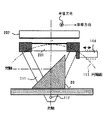
図10及び図11は第1の実施例における光ピックアップにおける収差補正駆動装置110の一例を示す。
図10に示すように、本体ユニット50の照射光学系には、そのベース部50a上に、立ち上げ反射鏡20が設けられている。立ち上げ反射鏡20は、半導体レーザ1から発射され、順にコリメータレンズ2、偏光ビームスプリッタ3、及び1/4波長板18を透過する光軸を、対物レンズ4へ立ち上げる。立ち上げ反射鏡20の光軸に対して45度の角度で交わる鏡面によって直角に光路が偏向される。
【0042】
第2補正板102は、図示しないジグによってベース部50aに固定される。第2補正板102から平行に離間する第1補正板101は、偏向され対物レンズ4へ入射する光軸に垂直に、すなわちそれらの光軸が照射光軸に一致するように、2枚の平行バネ105,106によって支えられている。よって、第2補正板102に対して第1補正板101が平行を維持したまま移動自在となっている。第1補正板101は、アクチュエータ114により、アクチュエータ駆動回路121からの光ディスクの傾き量に対応する出力に応じて、接線方向に駆動される。
【0043】
検出光学系の1/4波長板18を貼着した偏光ビームスプリッタ3と対物レンズ4との間に、収差補正装置を設けているので、照射光ビーム及び戻り反射光におけるコマ収差を良好に補正することができる。なお、ここで用いられる偏光ビームスプリッタ3は、半導体レーザ1からコリメータレンズ2を経た平行光ビームをビーム整形しつつ対物レンズ4へ導くと同時に光ディスクからの反射光を4分割光検出器9へ導くような検出光学系の一部の機能を有する複合プリズムである。
【0044】
次に第1の実施例における収差補正駆動装置を用いた光ピックアップにの動作について述べる。図10に示すように、半導体レーザ1から放射された直線偏光光ビームは、コリメータレンズ2で平行化され、偏光ビームスプリッタ3で整形され、1/4波長板18で円偏光化され、立ち上げ反射鏡20により、光ディスク5にほぼ垂直な照射光学系光軸に沿って対物レンズ4へ向けて偏向される。そして、図11に示すように、光ビームは収差補正装置の第1及び第2補正板101,102を透過して所定の光路長分布を付与され、対物レンズ4で集光され光ディスク5の記録面上に光スポットを形成する。光ディスク5の透明基板にてコマ収差が相殺され、光スポットからの反射光は、対物レンズ4、収差補正装置の第1及び第2補正板101,102及び立ち上げ反射鏡20を経て、1/4波長板18で直線偏光化され、偏光ビームスプリッタ3の誘電体多層膜にて反射され検出用集光レンズ7へ分離され、非点収差発生素子のマルチレンズ8を経て、4分割光検出器9へ入射する。マルチレンズ8は、光ディスク5の記録面に集光された光ビームの合焦時は真円の光スポットを4分割光検出器9に照射し、フォーカスが合っていない時は、エレメントの対角線方向に楕円の光スポットを4分割光検出器9に照射する、いわゆる非点収差を生ぜしめる。
【0045】
4分割光検出器9は、図9に示すように4つの各受光面に照射された光スポットの部分をその強度に応じて各々電気信号に光電変換して信号検出回路12に供給する。信号検出回路12は、4分割光検出器9から供給される電気信号に基づいてフォーカスエラー信号及びトラッキングエラー信号を生成し、アクチュエータ駆動回路13に供給する。アクチュエータ駆動回路13はそれぞれの駆動信号をアクチュエータ15に供給する。アクチュエータ15は、各駆動信号に応じて対物レンズ4を対応する方向に移動せしめる。ここで、収差補正装置によって、常時収差の補正をかけているので、コマ収差と、コマ収差とが互いに打ち消し合うようにして、全体として光源から光ディスクに到る光学系全体がもつ収差をほぼ最小にすることができる。
【0046】
本発明の第2の実施例を図12〜図18において説明する。これら図において第1の実施例の部材と同一の部材は同一の参照符合にて示される。
第2の実施例では、図11に示す上記実施例の2枚の平行バネ105,106に支持された第1補正板101が平行移動する駆動装置に代えて、図12に示すように、第1補正板201が揺動する駆動装置を用いる。第1及び第2補正板201,202は、第1の実施例の第1及び第2補正板101,102に相当するが、それぞれの曲面の面形状のやや異なる収差補正レンズである。
【0047】
図12に示すように、本体ユニット50の照射光学系においても、第2補正板202は、図示しないジグによってベース部50aに固定され、第2補正板202から平行に離間する第1補正板201は、偏向され対物レンズ4へ入射する光軸に垂直に、すなわちそれらの光軸が照射光軸に一致するように支持部材111によって支持されている。支持部材111は、光軸と交差する光ディスク5の半径方向へ伸長する回転軸112を中心にベース部50aに軸支さているので、図11に示すように、第1補正板201は回転軸112を中心とした円筒面113内において光ディスク5の接線方向へ移動自在である。支持部材111は、アクチュエータ114により、アクチュエータ駆動回路121からの光ディスクの傾き量に対応する出力に応じて、第1補正板201とともに駆動される。
【0048】
また、図20に示すように、支持部材111の代わりに、第1補正板201が照射光学系光軸上の1点Sを中心として枢支されたピボット支持部材117の上面に第1補正板201を固定して、第1補正板201が点Sを中心とした球面113内において駆動されるようにすることもできる。この場合、光ディスク5の接線方向に駆動するアクチュエータ114に加えて、半径方向に駆動するアクチュエータ118を設けることにより、接線方向に加えて、半径方向のコマ収差を同時に高速に補正できるようになる。
【0049】
図14に示す第2の実施例の収差補正装置100Aにおいても、第1補正板201及び第2補正板202は、離間して対向する互いに相補的な非球面である曲面201a及び202aをそれぞれ有する。第1及び第2補正板201,202の対向する曲面201a及び202aの反対側は、初期状態において互いに平行で平坦な面201b及び202bである。第1及び第2補正板201,202の少なくとも一方は曲面の光軸が光ビームの光路の光軸に略平行にかつ垂直方向に移動自在に保持されていればよい。
【0050】
次に、第1及び第2補正板の曲面201a及び202aの面形状について説明する。ここで、回転軸112から第1補正板201までの距離は、第1補正板201が第2補正板202に対して移動する距離より十分大きくとられているものとして説明する。
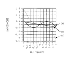
図14に示すように、第1補正板201の回転軸112側の面201bは平面となっているので、この回転駆動によって、入射平行光ビームに対しその平面201bは傾斜する。図15(C)の光路長差の変化に示すように、これは入射する平行光に対して駆動方向への変移を与える。このとき、図15(A)に示す透明ディスク基板の傾きによる収差がこの素子傾斜変移分を含めて補正されればよいので、収差補正を行なう量は図15(B)に示すようなもので良い。これに伴い、面形状の係数a,bを決定する。当該係数a,bは数値計算によって第1補正板201と第2補正板202の面形状を収差の発生を最小に抑えるように決定することができる。
【0051】
いま、第1実施例と同様に光ディスク傾きによる収差の代表的な形である、光軸からの距離の3次関数に比例して位相差が発生する場合を考える。このときの位相差は半径方向に沿って図16に示すように変化している。このとき、この面201a及び202aでは、第1実施例の位相差からさらに反対面の傾きによる変移分を除いたものを補正すればよいので、光路長差OPD0は光軸からの距離をxとして、この傾きをβxとして
【0052】
【数14】
OPD0(x,y)=αx3−αx+βx
と表すことができる。このとき、補正すべき波面は図16に示すようなものである。
この補正を与える第1補正板201の面形状は図17及び図18に示した形状となり、その厚さの最大値は光軸Oから最外周部OM側に行く中間Pの位置に存在するようになっている。すなわち、中心部Oが凹部であり、有効径内の外側において凸環状部Pが形成されている。また、第2補正板202の形状はこれとは逆に、図19に示すように中心部Oが凸部であり、有効径内の外側において凹環状部Pが形成されている。
【0053】
第2の実施例によれば、収差補正板の面形状を第1の実施例よりも平面に近く設計できるために、作成が容易である。また、回転軸112によって支えられて駆動するので、駆動時の変移や面の揺れを小さく抑えることができ、良好な性能を得ることができる。
以上説明したように、この収差補正板は補償しようとする光学系と設定する移動量が決まればその形状を決定できるので、精密NC加工機を用いて金型を製作し、ガラスのプレス加工あるいは樹脂成形によって安価に大量生産が可能である。補正板の一方を微動アクチュエータに取り付け、検出された光ディスク傾き量、あるいはコマ収差量信号に基づいてこのアクチュエータを駆動して、光ディスク傾きによる収差を常に押え込むようなサーボ系を構成することができる。ここで、アクチュエータは高い周波数に亘るまで動作をするものを用いることができるので、光ディスクの傾きが一周のうちで何度も変動するような形状の光ディスクを用いても良好な信号の再生が可能になる。また、このサーボは信号の振幅やジッタなどの品質をモニタし、常に最良の信号を得るように制御する手法を用いても構成できる。
【0054】
上記実施例においては瞳上距離の4乗に比例する成分のみを扱って形状を示した。ディスクの傾きのみに起因するコマ収差を補正するためには、上記実施例通りで対応できるが、光ディスクの透明基板の厚みが均一でない歪んだものに対応させるために、瞳上距離の6乗、8乗、10乗といった更に高次の偶数次の成分を加えることによって5次、7次、9次といった高次の収差成分の補正をすることができる。
【0055】
なお、この場合は、曲面の式5を
【数15】
z=(ax)6−(bx)4+Cx2+Dx
に当てはめて求めることができる。なお、この場合も各項の係数は3次の補正と同様な手法を用いて決定することができる。
上記実施例においては接線方向の傾き補正を行なう場合を例にとって示したが、収差補正板方向及びその駆動方向を光ディスクに対して回転させて、同様に半径方向の光ディスク傾きを補正するように構成することができる。
【0056】
また、上記補正板を半径方向と接線方向との双方に研磨し、一つの収差補正板をx軸及びy軸に駆動することによって2方向の傾きを同時に補正する構成も可能である。この場合、部品の工作加工及び調整を容易にするために、図21及び図22の等高線図に示すように、それぞれ光軸Oに対して軸対称な曲線形状を有する補正板301及び401として用いることもできる。
【0057】
上記実施例では面の傾き角度が僅かであるので第1補正板と第2補正板の間にできる空気間隙による悪影響は小さいが、もっと大きいコマ収差を補正するような場合や高精度の補正が必要な用途などにおいては、この間隙による光線の変移をあらかじめ計算して第1補正板あるいは第2補正板の面形状を決めることができる。
【0058】
上記実施例においては発生する収差を正確に取り去るように補正板の面の形状を決定したが、補正板の面の形状は、エッチング方法などを用いて、例えば何段かのステップ状の平面で構成することもできる。こうすることによって、簡便に収差補正板を作成することが可能になる。
本発明は、第1及び第2補正板の対向しない側の面を平面ではなく曲率を持ったレンズとすることでコリメータレンズなどの機能を持たせるようにも構成できる。また、この非対向面をホログラムとして、サーボ信号の発生やビームの分割などの機能を持たせる構成も可能である。また、この外側の非対向面の一つを反射面とし、この収差補正板を往復する光に対して位相差を与えるような構成も可能である。各面の形状は補正したい波面形状に応じて様々な設計が可能であり、要は補正板の一方を移動することによって通過光路長が非対称に変化するようなものであれば、同様の効果を得ることができる。
【0059】
上記実施例においては、アクチュエータの巻き線コイルを用いた普通の電磁アクチュエータの他に、圧電素子を用いたアクチュエータを用いるなど、様々な構成方法が可能である。
上記実施例においては、光ディスクの記録再生に用いるピックアップ装置を例にとって説明を行なったが、本装置はこれに限らず、顕微鏡装置、天体望遠鏡など、コマ収差の補正が必要となるいろいろな光学装置に適用することが可能である。このような場合には上記収差補正板の移動量を自動制御することなく、手動によって収差を調整するような簡単な構成も可能である。
【0060】
【発明の効果】
本発明においては、上述のように構成したことにより、僅かな方正板の移動によって高速かつ正確に光ディスクの透明板の傾きによる収差の補正を行い、かつ対物レンズを透過する光の進行方向を変えないので、高開口数対物レンズを使用するシステムにおいてもある程度の厚さを持つ光ディスクの透明板を使用することが可能になり、光ディスクの汚れ、ディフェクトなどに対する余裕度の高いシステムを構成することが可能になる。また、フレキシブルな透明基板材料を用いた光カード、光ディスクなどの高密度記録再生の道をも開くものである。
【図面の簡単な説明】
【図1】コマ収差補正方法を実行する装置の概略断面図。
【図2】光ディスク基板が傾いた場合の収差による光路長差の変化を示すグラフ。
【図3】実施例の光ピックアップ装置における収差補正装置の概略断面図。
【図4】実施例の光ピックアップ装置における収差補正装置の光路長差の変化を示すグラフ。
【図5】実施例の光ピックアップ装置における収差補正装置の概略断面図。
【図6】実施例の光ピックアップ装置における収差補正装置の概略平面図。
【図7】実施例の光ピックアップ装置における収差補正装置の概略断面図。
【図8】実施例の光ピックアップ装置における収差補正装置の光路長差の逆の変化を示すグラフ。
【図9】本発明の光ピックアップ装置を示す概略構成図。
【図10】実施例の光ピックアップ装置の照射光学系と検出光学系との関係を示す概略部分斜視図。
【図11】実施例の光ピックアップ装置における収差補正装置の駆動機構を示す概略断面図。
【図12】他の実施例の光ピックアップ装置における収差補正装置の駆動機構を示す概略断面図。
【図13】他の実施例の光ピックアップ装置の照射光学系と検出光学系との関係を示す概略部分斜視図。
【図14】他の実施例の光ピックアップ装置における収差補正装置の概略断面図。
【図15】他の実施例の光ピックアップ装置における収差補正装置の光路長差の変化を示すグラフ。
【図16】他の実施例の光ピックアップ装置における収差補正装置の光路長差の逆の変化を示すグラフ。
【図17】他の実施例の光ピックアップ装置における収差補正装置の概略断面図。
【図18】他の実施例の光ピックアップ装置における収差補正装置の概略平面図。
【図19】他の実施例の光ピックアップ装置における収差補正装置の概略断面図。
【図20】他の実施例の光ピックアップ装置における収差補正装置の概略平面図。
【図21】他の実施例の光ピックアップ装置における収差補正装置の概略平面図。
【図22】他の実施例の光ピックアップ装置における収差補正装置の概略平面図。
【主要部分の符号の説明】
1 半導体レーザ
2 コリメータレンズ
3 偏光ビームスプリッタ
4 対物レンズ
5 光ディスク
7 検出レンズ
8 マルチレンズ
9 4分割光検出器
12 信号検出回路
13、121 アクチュエータ駆動回路
50 本体ユニット
101、102、201、202 補正板
111 支持部材
114 アクチュエータ[0001]
BACKGROUND OF THE INVENTION
The present invention relates to an optical pickup device in an optical information recording / reproducing apparatus for reading / writing a signal from an optical disk which is an optical information recording medium.
[0002]
[Prior art]
In order to improve the recording density on the optical disc, it is conceivable to increase the numerical aperture of the objective lens of the optical pickup device. For example, the numerical aperture is increased from 0.45 to 0.6. At this time, in a standard that is determined to transmit information from the information recording surface through a transparent disk substrate having a predetermined thickness, coma aberration occurs due to the inclination of the transparent disk substrate, and an appropriate light spot is generated. It becomes impossible to irradiate the information recording surface. In particular, the amount of coma aberration increases remarkably as the numerical aperture increases. Therefore, when an optical disc is manufactured inexpensively using a transparent disc substrate formed by injection molding or the like, the inclination due to warping of the optical disc increases and the coma becomes large. Largely affected by aberrations.
[0003]
In order to reduce the influence of the coma aberration, the thickness of the transparent disk substrate is reduced. For example, the substrate thickness is reduced from 1.2 mm to 0.6 mm. As a result, the surface of the optical disk is significantly affected by dirt, scratches, etc., and there is a problem in that the optical disk performance deteriorates due to long-term use.
In addition, it is conceivable to use a tilt servo mechanism that attaches an optical disc tilt adjustment mechanism to the pickup device and tilts the pickup itself following the optical disc tilt. There is a concern that the response speed is large and slow. For this reason, the tilt of the pickup itself cannot follow the tilt fluctuation during one rotation of the optical disk, particularly the tilt in the time axis direction (tangential direction). Therefore, correction of coma aberration due to tangential tilt becomes a problem in a pickup device using an objective lens having a large numerical aperture.
[0004]
[Problems to be solved by the invention]
As a method for correcting coma aberration, a technique as disclosed in Japanese Patent Laid-Open No. 7-140381 is known. As shown in FIG. 1, two
[0005]
Here, if the
[0006]
FIG. 2A shows a change in the optical path length difference in the pupil due to aberration when the transparent disk substrate of the
[0007]
This aberration is caused by the tilt of the transparent disk substrate of the optical disk, and the curve shape of the optical path length difference shown in FIG. 2 is rising to the left because of the wavefront caused by the tilt of the transparent disk substrate, that is, from the optical axis. Represents the deflection of the light traveling direction.
For example, in the optical path from the light source to the objective lens, this wavefront aberration can be corrected by inserting the compensation plate for the inverse wavefront aberration in the form as it is (FIG. 2A). In addition to constructing a wavefront for tying, deflection is given in the traveling direction of the light after passing through the compensation plate. As shown in FIG. 1, this deflection is a bad effect that the light beam is incident on the objective lens from an oblique direction. Creates an effect and degrades imaging performance. In addition, when used to correct tangential tilt, optical pickups generally do not have a means to adjust the irradiation position in the tangential direction, so this deflection creates a shift in the irradiation position, and this shift causes tangential jitter. It becomes. In addition, since a necessary aberration correction amount in the peripheral portion is large, a correction error due to a position shift that becomes severer in proportion to the correction amount also increases, and it is difficult to realize with a large numerical aperture.
[0008]
That is, according to this conventional method, the optical axis is deflected by the movement of the inserted compensation plate, and the center position of the spot irradiated on the optical disk changes. This deflection of the irradiation optical axis particularly acts as time-varying noise (jitter) in correcting the tangential direction, and there is a problem that the tilt correction in the tangential direction cannot be performed satisfactorily. The present invention has been made in view of the above-described points, and in the conventional correction of coma aberration, an optical pickup device capable of satisfactorily removing a time-varying noise component by preventing deflection of an irradiation optical axis caused by movement of a compensation plate. The purpose is to provide.
[0009]
[Means for Solving the Problems]
An aberration correction apparatus according to the present invention is an aberration correction apparatus disposed in an optical path from a light source of an optical pickup device that irradiates a light beam to an optical disk to an optical disk,
It consists of a pair of light transmitting substrates having curved surfaces that are spaced apart and opposed to each other, and at least one of the light transmitting substrates is held movably in a direction perpendicular to the optical axis of the optical path,
The curved surface isNext formula
[Expression 4]
z = (Ax) 6 -(Bx) Four + Cx 2 + Dx
(Where, z is a height in a direction parallel to the optical axis, and x is a radius around the optical axis),
Each coefficient in the formula isIn order to minimize the coma aberration given to the transmitted light beam by the transparent plate of the optical disc, the optical path length of the light beam transmitted through the pair of light transmissive substrates is changed by the movement of the light transmissive substrate. The phase difference maintains the traveling direction of the light beam while giving the phase difference.Has been determined,It is characterized by that.
[0010]
In the aberration correction apparatus of the present invention, the curved surface is symmetric with respect to at least a radius or a tangential direction of the optical disc.
In the aberration correction apparatus of the present invention, the curved surface has the following formula:
[0011]
[Equation 5]
z = (ax)Four-(Bx)2
(In the formula2a2= B).
In the aberration correction apparatus of the present invention, one surface shape of the light transmission substrate is convex around the optical axis, and the surface normal at the outermost effective diameter is parallel to the optical axis, and the other light transmission substrate The substrate is characterized in that the surface shape is concave around the optical axis, and the surface normal at the outermost portion in the effective diameter is parallel to the optical axis.
[0012]
In the aberration correction apparatus of the present invention, one surface shape of the light transmission substrate is a convex surface around the optical axis, and a concave portion is formed outside the effective diameter, and the surface normal at the bottom of the concave portion is the optical axis. The other light-transmitting substrate has a concave surface around the optical axis and a convex portion formed outside the effective diameter, and the surface normal at the top of the convex portion is relative to the optical axis. It is characterized by being configured to be parallel.
[0013]
In the aberration correction apparatus of the present invention, one of the shapes of the light transmitting substrate is a convex surface centered on the symmetry plane with the plane including the optical axis as the symmetry plane, and the surface normal at the outermost portion within the effective diameter is It is parallel to the optical axis, the other light transmitting substrate is a concave surface centered on the symmetry plane, and the surface normal at the outermost effective diameter is parallel to the optical axis. To do.
[0014]
In the aberration correction apparatus of the present invention, one of the shapes of the light transmitting substrate is a convex surface centered on the symmetry plane with a plane including the optical axis as a center, and a recess is formed inside and outside the effective diameter. The surface normal of the bottom surface of the concave portion is parallel to the optical axis, the other light transmitting substrate is a concave surface centered on the symmetry plane, and a convex portion is formed inside and outside the effective diameter. The surface normal of the bottom surface of the convex portion is parallel to the optical axis.
[0015]
In the aberration correction apparatus of the present invention, at least one of the light transmission substrates is driven in a cylindrical surface centered on one point on the optical axis.
In the aberration correction apparatus of the present invention, at least one of the light transmission substrates is driven within a spherical surface centered on one point on the optical axis.
An optical pickup device of the present invention includes a light source that emits a light beam, an objective lens that focuses the light beam onto an information recording surface of an optical disc, an irradiation optical system that guides the light beam to the objective lens, and a light detection unit An optical pickup device that reads and / or writes a signal from an optical disc, comprising: a detection optical system that guides reflected light from the information recording surface to the light detection means via the objective lens,
Inclination detecting means for detecting an inclination of at least a radius or a tangent direction of the optical disc;
The light-transmitting substrate includes a pair of light-transmitting substrates that are disposed in the irradiation optical system and have mutually opposing curved surfaces that are spaced apart from each other, and at least one of the light-transmitting substrates has an optical axis of the curved surface substantially parallel to the optical axis of the optical path And is movably held in a direction perpendicular to the optical axis of the optical path, and the curved surface isNext formula
[Formula 6]
z = (Ax) 6 -(Bx) Four + Cx 2 + Dx
(Wherein z is a height in a direction parallel to the optical axis, and x is a radius centered on the optical axis) satisfying an aspherical surface,The phase difference maintains the traveling direction of the light beam while changing the optical path length of the light beam transmitted through the pair of light transmissive substrates by moving the light transmissive substrate to give a phase difference to the transmitted light beam.Has been determined,An aberration correction device;
The light transmission substrate is moved in a direction perpendicular to the optical axis of the optical path in accordance with the output corresponding to the tilt amount of the optical disk from the tilt detection means, and at least the radius given to the transmitted light beam by the transparent plate of the optical disk Or an aberration correction driving unit that minimizes coma in the tangential direction.
[0016]
In the optical pickup device of the present invention, at least one of the light transmitting substrates is driven in a cylindrical surface centering on a rotation axis extending in a radial direction of the optical disc that intersects the optical axis. .
In the optical pickup device of the present invention, at least one of the light transmitting substrates is driven within a spherical surface centered on one point on the optical axis.
[0017]
According to the aberration correction device in the optical pickup device of the present invention, two light transmission substrates having partially different thicknesses in the irradiation optical axis direction are made substantially parallel so that their optical axes substantially coincide with the irradiation optical axis. The optical path of the transmitted light, that is, the total thickness of the light transmissive substrate can be partially varied by moving one of the light transmissive substrates substantially perpendicular to the irradiation optical axis. Thereby, a predetermined phase difference distribution is given to the transmitted light beam, and wavefront correction can be performed at high speed with a small correction amount. Further, the aberration can be corrected without causing the light spot to change due to the deflection of the transmitted light, and the time-axis fluctuation noise component can be removed satisfactorily. As described above, in the optical pickup apparatus according to the present invention, the irradiation light caused by the movement of the compensation plate is changed by suppressing or removing the deflection of the optical axis by changing the partial optical path length of the transmitted light beam by the movement of the light transmission substrate. Prevents deflection of the axis and does not shift the irradiation light spot.
[0018]
DETAILED DESCRIPTION OF THE INVENTION
Embodiments of the present invention will be described below with reference to the drawings.
An
[0019]
Since the light beam is refracted and reflected many times and guided to the optical disc, the optical axis of the light beam at the position where the correction plate is disposed is not necessarily perpendicular to the optical disc surface. Therefore, the correction plate is not limited to one that moves in a direction parallel to the radial direction or tangential direction of the optical disc, but a direction corresponding to the tangential direction or radial direction on the optical disc surface of the light beam irradiated on the optical disc surface. Move to.
[0020]
The
[0021]
The correction plate for correcting coma aberration in one of the tangential direction and the radial direction is a plane including the optical axis and the tangential direction or the radial direction on the optical disc surface of the light beam irradiated on the optical disc surface. A plane parallel to the direction corresponding to is called a symmetry plane.
In addition, for a correction plate that corrects both tangential and radial coma, the axis parallel to the optical axis is the axis of symmetry.
[0022]
Next, the surface shapes of the
[0023]
In this embodiment, the wavefront aberration generated when the substrate is tilted is corrected by inserting the above-described conventional compensation plate that generates the inverse wavefront aberration in the form as it is (FIG. 2). Instead, a correction plate having a curved surface to which wavefront aberration with reduced deflection in the traveling direction of light is used. In general, coma aberration greatly depends on the entrance pupil diameter in relation to the aberration with respect to the entrance pupil diameter of an optical element such as a lens. That is, as the entrance pupil numerical aperture increases, the coma aberration also increases. Therefore, in addition to giving a coma aberration opposite to the coma aberration of the disk substrate by the aberration correction device to cancel the coma aberration, by changing the optical path length from the paraxial to the outer periphery of the optical element to reduce it. The deflection of the optical axis can be suppressed.
[0024]
Therefore, the
[0025]
In other words, the phase difference shape of the wavefront to be corrected in the present invention is, as shown in FIG. 4, FIG. It is a phase difference shape as shown in B).
5, 6 and 7 show the surface shapes of the
[0026]
FIG. 5 is a cross-sectional view showing the thickness in the radial direction of the
[0027]
The
[0028]
The aberration correction device is arranged such that the two first and
Next, a design example of the surface shapes of the
[0029]
[Expression 7]
OPD0(X, y) = αxThree-Αx
It can be expressed as.
The convex shape of the
[0030]
[Equation 8]
z1= (Ax)Four-(Bx)2
It is assumed that the surface shape. Here, the value of the constant a will be specified later.
The convex shape of the
[0031]
[Equation 9]
z2= (Ax)Four-(Bx)2
It is. If the distance between the
[0032]
[Expression 10]
OPD (x, y) = z2(X) -z1(X) = 0
Thus, there is no change in the wavefront phase difference distribution due to passing through these two sheets.
Next, a phase difference when the
[0033]
[Expression 11]
OPD (x; y + Δx, y) = z1(X) -z2(X + Δx)
= 4aFourΔxxThree-2b2Δxx + 6aFourΔx2x2-B2Δx2+ 4aFourΔxThreex + aFourΔxFour
Here, if a term greater than or equal to the square of Δx is ignored,
[0034]
[Expression 12]
OPD = 4aFourΔxxThree-2b2Δxx
It becomes. Here, x represents the pupil radius as a unit,
[0035]
[Formula 13]
2a2= B
If so, the wavefront having the change of FIG. 4B can be corrected. That is, when the above design is simply summarized, the optical path difference shown in FIG. 4B is added to the optical path difference shown in FIG. 8 opposite to the optical path difference to cancel the phase difference. .
[0036]
An optical pickup apparatus that reads and / or writes a signal from an optical disk using the aberration correction apparatus of the first embodiment will be described.
FIG. 9 shows an optical pickup device using the astigmatism method. In a recording / reproducing apparatus for recording / reproducing information by loading an
[0037]
The optical pickup device is roughly divided into an objective lens unit and a main unit that supports the objective lens unit. The main unit is fixed to a slider mechanism that moves on a shaft extending in the radial direction of the
As shown in FIG. 9, the objective lens unit includes an
[0038]
As shown in FIG. 9, the main unit includes a
[0039]
A pair of first and
[0040]
The tilt
[0041]
10 and 11 show an example of the aberration
As shown in FIG. 10, in the irradiation optical system of the main unit 50, a rising reflecting
[0042]
The
[0043]
Since the aberration correction device is provided between the
[0044]
Next, the operation of the optical pickup using the aberration correction driving apparatus in the first embodiment will be described. As shown in FIG. 10, the linearly polarized light beam emitted from the
[0045]
As shown in FIG. 9, the four-divided
[0046]
A second embodiment of the present invention will be described with reference to FIGS. In these drawings, the same members as those of the first embodiment are indicated by the same reference numerals.
In the second embodiment, as shown in FIG. 12, the
[0047]
As shown in FIG. 12, also in the irradiation optical system of the main unit 50, the
[0048]
As shown in FIG. 20, instead of the support member 111, the
[0049]
Also in the
[0050]
Next, the surface shapes of the
As shown in FIG. 14, since the surface 201b of the
[0051]
Now, let us consider a case where a phase difference is generated in proportion to a cubic function of the distance from the optical axis, which is a typical form of aberration due to the tilt of the optical disk, as in the first embodiment. The phase difference at this time changes along the radial direction as shown in FIG. At this time, in the
[0052]
[Expression 14]
OPD0(X, y) = αxThree-Αx + βx
It can be expressed as. At this time, the wavefront to be corrected is as shown in FIG.
The surface shape of the
[0053]
According to the second embodiment, the surface shape of the aberration correction plate can be designed to be closer to a plane than in the first embodiment, so that the creation is easy. In addition, since it is supported and driven by the
As described above, since the shape of the aberration correction plate can be determined once the optical system to be compensated and the amount of movement to be set are determined, a mold is manufactured using a precision NC processing machine, and glass pressing or Mass production at low cost is possible by resin molding. A servo system can be constructed in which one of the correction plates is attached to a fine movement actuator and this actuator is driven based on the detected optical disc tilt amount or coma aberration amount signal to constantly suppress aberration due to the optical disc tilt. . Here, since an actuator that operates up to a high frequency can be used, good signal reproduction is possible even with an optical disk having a shape in which the inclination of the optical disk fluctuates many times within one round. become. This servo can also be configured by using a method of monitoring the quality of the signal amplitude, jitter and the like and always controlling so as to obtain the best signal.
[0054]
In the above embodiment, only the component proportional to the fourth power of the distance above the pupil is handled and the shape is shown. In order to correct the coma caused by only the tilt of the disc, it can be dealt with as in the above embodiment, but in order to cope with the distortion of the transparent substrate of the optical disc that is not uniform, By adding higher-order even-order components such as the eighth power and the tenth power, higher-order aberration components such as the fifth, seventh, and ninth orders can be corrected.
[0055]
In this case, the curved surfaceFormula 5The
[Expression 15]
z = (ax)6-(Bx)Four+ Cx2+ Dx
Can be applied to. In this case as well, the coefficient of each term can be determined using the same method as the third-order correction.
In the above embodiment, the case of correcting the tangential tilt is shown as an example, but the configuration is such that the optical disc tilt in the radial direction is similarly corrected by rotating the aberration correction plate direction and its driving direction with respect to the optical disc. can do.
[0056]
It is also possible to correct the tilt in two directions simultaneously by polishing the correction plate in both the radial direction and the tangential direction and driving one aberration correction plate in the x-axis and y-axis. In this case, in order to facilitate the machining and adjustment of the parts, as shown in the contour diagrams of FIGS. 21 and 22, they are used as
[0057]
In the above embodiment, since the inclination angle of the surface is small, the adverse effect of the air gap formed between the first correction plate and the second correction plate is small. However, in the case where a larger coma aberration is corrected, high accuracy correction is necessary. In applications and the like, the surface shape of the first correction plate or the second correction plate can be determined by calculating in advance the shift of the light beam due to this gap.
[0058]
In the above embodiment, the shape of the surface of the correction plate is determined so as to accurately remove the generated aberration. However, the shape of the surface of the correction plate is determined by, for example, several stepped planes using an etching method or the like. It can also be configured. By doing so, an aberration correction plate can be easily created.
The present invention can also be configured to have a function such as a collimator lens by making the surfaces of the first and second correction plates that do not face each other into a lens having a curvature instead of a flat surface. In addition, it is possible to adopt a configuration in which this non-facing surface is used as a hologram to have functions such as generation of servo signals and beam splitting. Further, it is possible to adopt a configuration in which one of the outer non-facing surfaces is a reflecting surface and a phase difference is given to the light traveling back and forth through the aberration correction plate. The shape of each surface can be designed in various ways depending on the wavefront shape to be corrected. In short, the same effect can be obtained if the passing optical path length changes asymmetrically by moving one of the correction plates. Can be obtained.
[0059]
In the above embodiment, various configuration methods such as using an actuator using a piezoelectric element in addition to a normal electromagnetic actuator using a wound coil of the actuator are possible.
In the above embodiment, the description has been given by taking the pickup device used for recording / reproducing of the optical disk as an example. It is possible to apply to. In such a case, a simple configuration in which the aberration is adjusted manually without automatically controlling the movement amount of the aberration correction plate is possible.
[0060]
【The invention's effect】
In the present invention, the optical disk is transmitted through the optical disk at high speed and accurately by the slight movement of the square plate.Light boardCorrection of aberration due to the tilt of the light source and the direction of travel of the light transmitted through the objective lens is not changed. Therefore, even in a system using a high numerical aperture objective lens, an optical disc having a certain thickness can be transmitted.Light boardCan be used, and it is possible to configure a system with a high margin for contamination, defects, etc. of the optical disk. It also opens the way for high-density recording and reproduction of optical cards, optical disks, and the like using flexible transparent substrate materials.
[Brief description of the drawings]
FIG. 1 is a schematic cross-sectional view of an apparatus for executing a coma aberration correction method.
FIG. 2 is a graph showing a change in optical path length difference due to aberration when the optical disk substrate is tilted.
FIG. 3 is a schematic cross-sectional view of an aberration correction device in the optical pickup device of the embodiment.
FIG. 4 is a graph showing a change in optical path length difference of the aberration correction device in the optical pickup device of the example.
FIG. 5 is a schematic cross-sectional view of an aberration correction device in the optical pickup device of the embodiment.
FIG. 6 is a schematic plan view of an aberration correction device in the optical pickup device of the embodiment.
FIG. 7 is a schematic cross-sectional view of an aberration correction device in the optical pickup device of the embodiment.
FIG. 8 is a graph showing a reverse change in the optical path length difference of the aberration correction device in the optical pickup device of the example.
FIG. 9 is a schematic configuration diagram showing an optical pickup device of the present invention.
FIG. 10 is a schematic partial perspective view illustrating a relationship between an irradiation optical system and a detection optical system of the optical pickup device according to the embodiment.
FIG. 11 is a schematic cross-sectional view showing a drive mechanism of the aberration correction device in the optical pickup device of the embodiment.
FIG. 12 is a schematic cross-sectional view showing a drive mechanism of an aberration correction device in an optical pickup device of another embodiment.
FIG. 13 is a schematic partial perspective view showing a relationship between an irradiation optical system and a detection optical system of an optical pickup device according to another embodiment.
FIG. 14 is a schematic cross-sectional view of an aberration correction device in an optical pickup device of another embodiment.
FIG. 15 is a graph showing a change in optical path length difference of an aberration correction device in an optical pickup device of another example.
FIG. 16 is a graph showing an opposite change in the optical path length difference of the aberration correction device in the optical pickup device of another embodiment.
FIG. 17 is a schematic cross-sectional view of an aberration correction device in an optical pickup device of another embodiment.
FIG. 18 is a schematic plan view of an aberration correction device in an optical pickup device according to another embodiment.
FIG. 19 is a schematic cross-sectional view of an aberration correction device in an optical pickup device of another embodiment.
FIG. 20 is a schematic plan view of an aberration correction device in an optical pickup device of another embodiment.
FIG. 21 is a schematic plan view of an aberration correction device in an optical pickup device of another embodiment.
FIG. 22 is a schematic plan view of an aberration correction device in an optical pickup device of another embodiment.
[Explanation of main part codes]
1 Semiconductor laser
2 Collimator lens
3 Polarizing beam splitter
4 Objective lens
5 Optical disc
7 Detection lens
8 Multi lens
9 Quadrant photodetector
12 Signal detection circuit
13, 121 Actuator drive circuit
50 Main unit
101, 102, 201, 202 Correction plate
111 Support members
114 Actuator
Claims (12)
離間して対向する互いに相補的な曲面を有する一対の光透過基板からなり、前記光透過基板の少なくとも一方は前記光路の光軸に垂直方向に移動自在に保持され、
前記曲面は、次式
前記数式における各係数は、前記光ディスクの透明板によって透過光ビームに与えられるコマ収差を最小とすべく、前記一対の光透過基板を透過する光ビームの光路長が前記光透過基板の移動によって変化することにより透過光ビームに位相差を与えつつ該位相差が該光ビームの進行方向を維持するように決定されている、ことを特徴とする収差補正装置。An aberration correction device disposed in an optical path from a light source of an optical pickup device that irradiates a light beam to an optical disc to an optical disc,
It consists of a pair of light transmitting substrates having curved surfaces that are spaced apart and opposite each other, and at least one of the light transmitting substrates is held movably in a direction perpendicular to the optical axis of the optical path,
The curved surface is expressed by the following equation
Each coefficient in the mathematical formula varies with the movement of the light transmitting substrate so that the coma aberration given to the transmitted light beam by the transparent plate of the optical disc is minimized. Thus, the aberration correction apparatus is characterized in that the phase difference is determined so as to maintain the traveling direction of the light beam while giving the phase difference to the transmitted light beam.
前記光ディスクの少なくとも半径又は接線の方向に関する傾きを検出する傾き検出手段と、
前記照射光学系に配置され、離間して対向する互いに相補的な曲面を有する一対の光透過基板からなり、前記光透過基板の少なくとも一方は前記光路の光軸に垂直方向に移動自在に保持され、前記曲面は、次式
前記傾き検出手段からの前記光ディスクの傾き量に対応する出力に応じて、前記光透過基板を前記光路の光軸に垂直方向に移動せしめ、前記光ディスクの透明板によって透過光ビームに与えられる少なくとも半径又は接線方向のコマ収差を最小とする収差補正駆動手段と、を有することを特徴とする光ピックアップ装置。A light source that emits a light beam, an objective lens that focuses the light beam on an information recording surface of an optical disc, an irradiation optical system that guides the light beam to the objective lens, and a light detection unit that includes a light detection unit. A detection optical system that guides reflected light from the information recording surface to the light detection means, and an optical pickup device that reads and / or writes a signal from an optical disc,
An inclination detecting means for detecting an inclination of at least a radius or a tangent direction of the optical disc;
A pair of light-transmitting substrates that are disposed in the irradiation optical system and have mutually spaced curved surfaces that are spaced apart from each other, and at least one of the light-transmitting substrates is held movably in a direction perpendicular to the optical axis of the optical path. , the curved surface is expressed by the following equation
The light transmission substrate is moved in a direction perpendicular to the optical axis of the optical path according to the output corresponding to the tilt amount of the optical disk from the tilt detection means, and at least the radius given to the transmitted light beam by the transparent plate of the optical disk Or an aberration correction driving unit that minimizes coma in the tangential direction.
Priority Applications (2)
| Application Number | Priority Date | Filing Date | Title |
|---|---|---|---|
| JP35334998A JP3666632B2 (en) | 1998-12-11 | 1998-12-11 | Aberration correction apparatus and optical pickup apparatus using the same |
| US09/458,074 US6751175B1 (en) | 1998-12-11 | 1999-12-10 | Aberration correcting device and optical pickup apparatus using the same |
Applications Claiming Priority (1)
| Application Number | Priority Date | Filing Date | Title |
|---|---|---|---|
| JP35334998A JP3666632B2 (en) | 1998-12-11 | 1998-12-11 | Aberration correction apparatus and optical pickup apparatus using the same |
Publications (3)
| Publication Number | Publication Date |
|---|---|
| JP2000182268A JP2000182268A (en) | 2000-06-30 |
| JP2000182268A5 JP2000182268A5 (en) | 2005-04-07 |
| JP3666632B2 true JP3666632B2 (en) | 2005-06-29 |
Family
ID=18430248
Family Applications (1)
| Application Number | Title | Priority Date | Filing Date |
|---|---|---|---|
| JP35334998A Expired - Fee Related JP3666632B2 (en) | 1998-12-11 | 1998-12-11 | Aberration correction apparatus and optical pickup apparatus using the same |
Country Status (2)
| Country | Link |
|---|---|
| US (1) | US6751175B1 (en) |
| JP (1) | JP3666632B2 (en) |
Families Citing this family (17)
| Publication number | Priority date | Publication date | Assignee | Title |
|---|---|---|---|---|
| JP2002140831A (en) * | 2000-11-02 | 2002-05-17 | Sharp Corp | Optical pickup device |
| WO2002061488A1 (en) * | 2001-01-30 | 2002-08-08 | Matsushita Electric Industrial Co., Ltd. | Variable mirror and information apparatus comprising variable mirror |
| JP4014840B2 (en) | 2001-10-12 | 2007-11-28 | 株式会社日立製作所 | Coma aberration correcting element and optical system for optical head using the same |
| KR20040068944A (en) * | 2001-12-19 | 2004-08-02 | 코닌클리케 필립스 일렉트로닉스 엔.브이. | Optical scanning device |
| JP3849523B2 (en) * | 2001-12-26 | 2006-11-22 | ティアック株式会社 | Optical pickup and optical disc apparatus |
| CN100395579C (en) | 2002-01-29 | 2008-06-18 | 松下电器产业株式会社 | Shape-variable mirror and light control device having the shape-variable mirror |
| AU2003277565A1 (en) | 2002-11-06 | 2004-06-07 | Matsushita Electric Industrial Co., Ltd. | Microactuator provided with diplacement detection function, and deformable mirror provided with this microactuator |
| DE10300810A1 (en) * | 2003-01-10 | 2004-07-22 | Deutsche Thomson-Brandt Gmbh | Device for reading and / or writing to optical recording media |
| JP2005108321A (en) * | 2003-09-30 | 2005-04-21 | Konica Minolta Opto Inc | Optical pickup device and optical information recording and reproducing device |
| WO2005078713A1 (en) * | 2004-01-19 | 2005-08-25 | Koninklijke Philips Electronics N.V. | Optical device with wavefront modifier |
| US7414929B2 (en) * | 2004-09-22 | 2008-08-19 | Lsi Corporation | Optical disc tilt detection and tilt servo control method |
| KR100746221B1 (en) * | 2005-12-23 | 2007-08-03 | 삼성전자주식회사 | Off-axis illumination apparatus and lithography apparatus and off-axis illumination method |
| US7779099B2 (en) * | 2006-03-16 | 2010-08-17 | Us Beverage Net Inc. | Distributed intelligent systems and methods therefor |
| JP2009170071A (en) * | 2007-09-20 | 2009-07-30 | Panasonic Corp | Optical pickup optical system, and optical pickup device using the same |
| JP2011028823A (en) * | 2008-10-31 | 2011-02-10 | Asahi Glass Co Ltd | Aberration correction device, optical device, and optical head device |
| DE102013101711A1 (en) | 2013-02-21 | 2014-08-21 | Carl Zeiss Microscopy Gmbh | Lens and optical observation device |
| JP6690217B2 (en) * | 2015-03-09 | 2020-04-28 | セイコーエプソン株式会社 | Light source device and projector |
Family Cites Families (5)
| Publication number | Priority date | Publication date | Assignee | Title |
|---|---|---|---|---|
| NL171641C (en) * | 1974-02-13 | 1983-04-18 | Philips Nv | DEVICE FOR READING A REGISTRATION BEARER ON WHICH INFORMATION IS INCLUDED IN AN OPTICALLY READABLE STRUCTURE. |
| US5202875A (en) * | 1991-06-04 | 1993-04-13 | International Business Machines Corporation | Multiple data surface optical data storage system |
| JPH0777031B2 (en) * | 1991-10-16 | 1995-08-16 | インターナショナル・ビジネス・マシーンズ・コーポレイション | Aberration compensator |
| JPH07140381A (en) * | 1993-11-18 | 1995-06-02 | Sony Corp | Method for correcting coma aberration |
| JP3691188B2 (en) * | 1996-12-09 | 2005-08-31 | パイオニア株式会社 | Tilt servo system |
-
1998
- 1998-12-11 JP JP35334998A patent/JP3666632B2/en not_active Expired - Fee Related
-
1999
- 1999-12-10 US US09/458,074 patent/US6751175B1/en not_active Expired - Fee Related
Also Published As
| Publication number | Publication date |
|---|---|
| US6751175B1 (en) | 2004-06-15 |
| JP2000182268A (en) | 2000-06-30 |
Similar Documents
| Publication | Publication Date | Title |
|---|---|---|
| KR100388515B1 (en) | Optical pickup apparatus | |
| KR100653289B1 (en) | Optical head and recording/reproducing device | |
| JP3666632B2 (en) | Aberration correction apparatus and optical pickup apparatus using the same | |
| KR100389071B1 (en) | Optical pick-up device | |
| JP3640059B2 (en) | Aberration correction apparatus and optical apparatus using the same | |
| US6741406B2 (en) | Objective lens, optical pickup-device equipped with same and assembling method of same | |
| JPH07140381A (en) | Method for correcting coma aberration | |
| JP3861586B2 (en) | Optical pickup device and recording / reproducing device | |
| US20060198254A1 (en) | Objective lens, optical pickup, and optical information processing apparatus | |
| US20050243674A1 (en) | Optical pickup, optical information processing apparatus and optical information processing method | |
| JPS62132247A (en) | Optical head device | |
| US7042817B2 (en) | Aberration detection device, aberration detection method, and optical pick-up device for controlling spherical aberration | |
| JP3787925B2 (en) | Objective lens device and recording / reproducing device | |
| JP4144763B2 (en) | Information pickup device and optical disk device | |
| JPH10134400A (en) | Optical head | |
| US7254098B2 (en) | CD-DVD compatible optical pickup and optical recording and/or reproducing apparatus using the same | |
| TWI224330B (en) | Optical pick-up and optical disc drive | |
| JP3744187B2 (en) | Optical head device | |
| JP2005535063A (en) | Scanning device including an objective lens formed of two kinds of materials | |
| JP2000501545A (en) | Apparatus for writing to and / or reading from optical storage media having different structures | |
| JPH11190818A (en) | Objective lens, optical head and recording and reproducing device | |
| US7130134B2 (en) | Optical scanning device | |
| WO2007108446A1 (en) | Optical head, optical disc device and optical head manufacturing method | |
| JP4333807B2 (en) | Information pickup device and optical disk device | |
| KR100607937B1 (en) | Apparatus for compensating tilt of optical disk and optical pickup apparatus adopting thereof |
Legal Events
| Date | Code | Title | Description |
|---|---|---|---|
| A521 | Written amendment |
Free format text: JAPANESE INTERMEDIATE CODE: A523 Effective date: 20040428 |
|
| A621 | Written request for application examination |
Free format text: JAPANESE INTERMEDIATE CODE: A621 Effective date: 20040428 |
|
| A977 | Report on retrieval |
Free format text: JAPANESE INTERMEDIATE CODE: A971007 Effective date: 20041112 |
|
| A131 | Notification of reasons for refusal |
Free format text: JAPANESE INTERMEDIATE CODE: A131 Effective date: 20041122 |
|
| A521 | Written amendment |
Free format text: JAPANESE INTERMEDIATE CODE: A523 Effective date: 20050117 |
|
| TRDD | Decision of grant or rejection written | ||
| A01 | Written decision to grant a patent or to grant a registration (utility model) |
Free format text: JAPANESE INTERMEDIATE CODE: A01 Effective date: 20050330 |
|
| A61 | First payment of annual fees (during grant procedure) |
Free format text: JAPANESE INTERMEDIATE CODE: A61 Effective date: 20050330 |
|
| R150 | Certificate of patent or registration of utility model |
Free format text: JAPANESE INTERMEDIATE CODE: R150 |
|
| FPAY | Renewal fee payment (event date is renewal date of database) |
Free format text: PAYMENT UNTIL: 20090415 Year of fee payment: 4 |
|
| FPAY | Renewal fee payment (event date is renewal date of database) |
Free format text: PAYMENT UNTIL: 20090415 Year of fee payment: 4 |
|
| FPAY | Renewal fee payment (event date is renewal date of database) |
Free format text: PAYMENT UNTIL: 20100415 Year of fee payment: 5 |
|
| FPAY | Renewal fee payment (event date is renewal date of database) |
Free format text: PAYMENT UNTIL: 20110415 Year of fee payment: 6 |
|
| FPAY | Renewal fee payment (event date is renewal date of database) |
Free format text: PAYMENT UNTIL: 20120415 Year of fee payment: 7 |
|
| LAPS | Cancellation because of no payment of annual fees |