EP1548534B1 - Verfahren und Gerät zur Verwendung einer Drehbewegungsmenge einer mobilen Vorrichtung und computerlesbares Speichermedium zum Speichern eines Computerprogrammes - Google Patents
Verfahren und Gerät zur Verwendung einer Drehbewegungsmenge einer mobilen Vorrichtung und computerlesbares Speichermedium zum Speichern eines Computerprogrammes Download PDFInfo
- Publication number
- EP1548534B1 EP1548534B1 EP04254937A EP04254937A EP1548534B1 EP 1548534 B1 EP1548534 B1 EP 1548534B1 EP 04254937 A EP04254937 A EP 04254937A EP 04254937 A EP04254937 A EP 04254937A EP 1548534 B1 EP1548534 B1 EP 1548534B1
- Authority
- EP
- European Patent Office
- Prior art keywords
- mobile device
- posture information
- movement amount
- checking
- obtaining
- Prior art date
- Legal status (The legal status is an assumption and is not a legal conclusion. Google has not performed a legal analysis and makes no representation as to the accuracy of the status listed.)
- Expired - Lifetime
Links
Images



Classifications
-
- G—PHYSICS
- G05—CONTROLLING; REGULATING
- G05D—SYSTEMS FOR CONTROLLING OR REGULATING NON-ELECTRIC VARIABLES
- G05D1/00—Control of position, course, altitude or attitude of land, water, air or space vehicles, e.g. using automatic pilots
- G05D1/20—Control system inputs
- G05D1/24—Arrangements for determining position or orientation
- G05D1/247—Arrangements for determining position or orientation using signals provided by artificial sources external to the vehicle, e.g. navigation beacons
-
- G—PHYSICS
- G05—CONTROLLING; REGULATING
- G05D—SYSTEMS FOR CONTROLLING OR REGULATING NON-ELECTRIC VARIABLES
- G05D1/00—Control of position, course, altitude or attitude of land, water, air or space vehicles, e.g. using automatic pilots
- G05D1/02—Control of position or course in two dimensions
- G05D1/021—Control of position or course in two dimensions specially adapted to land vehicles
- G05D1/0231—Control of position or course in two dimensions specially adapted to land vehicles using optical position detecting means
- G05D1/0246—Control of position or course in two dimensions specially adapted to land vehicles using optical position detecting means using a video camera in combination with image processing means
- G05D1/0253—Control of position or course in two dimensions specially adapted to land vehicles using optical position detecting means using a video camera in combination with image processing means extracting relative motion information from a plurality of images taken successively, e.g. visual odometry, optical flow
-
- G—PHYSICS
- G05—CONTROLLING; REGULATING
- G05D—SYSTEMS FOR CONTROLLING OR REGULATING NON-ELECTRIC VARIABLES
- G05D1/00—Control of position, course, altitude or attitude of land, water, air or space vehicles, e.g. using automatic pilots
- G05D1/20—Control system inputs
- G05D1/24—Arrangements for determining position or orientation
- G05D1/246—Arrangements for determining position or orientation using environment maps, e.g. simultaneous localisation and mapping [SLAM]
-
- G—PHYSICS
- G05—CONTROLLING; REGULATING
- G05D—SYSTEMS FOR CONTROLLING OR REGULATING NON-ELECTRIC VARIABLES
- G05D1/00—Control of position, course, altitude or attitude of land, water, air or space vehicles, e.g. using automatic pilots
- G05D1/02—Control of position or course in two dimensions
- G05D1/021—Control of position or course in two dimensions specially adapted to land vehicles
- G05D1/0268—Control of position or course in two dimensions specially adapted to land vehicles using internal positioning means
- G05D1/027—Control of position or course in two dimensions specially adapted to land vehicles using internal positioning means comprising intertial navigation means, e.g. azimuth detector
-
- G—PHYSICS
- G05—CONTROLLING; REGULATING
- G05D—SYSTEMS FOR CONTROLLING OR REGULATING NON-ELECTRIC VARIABLES
- G05D1/00—Control of position, course, altitude or attitude of land, water, air or space vehicles, e.g. using automatic pilots
- G05D1/02—Control of position or course in two dimensions
- G05D1/021—Control of position or course in two dimensions specially adapted to land vehicles
- G05D1/0268—Control of position or course in two dimensions specially adapted to land vehicles using internal positioning means
- G05D1/0272—Control of position or course in two dimensions specially adapted to land vehicles using internal positioning means comprising means for registering the travel distance, e.g. revolutions of wheels
-
- G—PHYSICS
- G05—CONTROLLING; REGULATING
- G05D—SYSTEMS FOR CONTROLLING OR REGULATING NON-ELECTRIC VARIABLES
- G05D2111/00—Details of signals used for control of position, course, altitude or attitude of land, water, air or space vehicles
- G05D2111/50—Internal signals, i.e. from sensors located in the vehicle, e.g. from compasses or angular sensors
- G05D2111/54—Internal signals, i.e. from sensors located in the vehicle, e.g. from compasses or angular sensors for measuring the travel distances, e.g. by counting the revolutions of wheels
-
- Y—GENERAL TAGGING OF NEW TECHNOLOGICAL DEVELOPMENTS; GENERAL TAGGING OF CROSS-SECTIONAL TECHNOLOGIES SPANNING OVER SEVERAL SECTIONS OF THE IPC; TECHNICAL SUBJECTS COVERED BY FORMER USPC CROSS-REFERENCE ART COLLECTIONS [XRACs] AND DIGESTS
- Y10—TECHNICAL SUBJECTS COVERED BY FORMER USPC
- Y10S—TECHNICAL SUBJECTS COVERED BY FORMER USPC CROSS-REFERENCE ART COLLECTIONS [XRACs] AND DIGESTS
- Y10S700/00—Data processing: generic control systems or specific applications
- Y10S700/90—Special robot structural element
Definitions
- the present invention relates to a mobile device, and more particularly, to a method and apparatus for obtaining an amount of rotational movement of a mobile device and using the same, and a computer-readable recording medium for storing a computer program.
- posture information of the mobile device should be obtained in real time.
- the posture information means information on the position and orientation (known herein also as "pose") of the mobile device.
- a conventional method in which the mobile device itself obtains the posture information is largely classified into a local tracking method and a global localization method. These methods are disclosed on page 10 of a technical report entitled "Where am I? Sensors and Methods for Mobile Robot Positioning" written by J. Borenstein, H. R. Everett, and L. Feng and published on April 1996, prepared by the University of Michigan for the Oak Ridge National Lab. D & D Program.
- the posture information can be simply recognized using odometry.
- this method has a problem of being sensitive to a kinematic modeling error and a unstructured error.
- error modeling and compensation methods have been developed and are disclosed on pages 132-150 of the above technical report, a thesis entitled “ Measurement and Correction of Systematic Odometry Errors in Mobile Robots” (J. Borenstein, and L. Feng, IEEE Transactions on Robotics and Automation, Vol. 12, No. 6, December 1996, pp.
- the position of the mobile device is estimated using a linear accelerometer while the pose of the mobile device is estimated using a gyro or compass.
- conventional filter design methods to stably estimate the posture information from a sensed signal exist.
- the conventional method of estimating the posture information by integrating the sensed result has problems of not only considerably degrading accuracy in recognizing posture information as time passes due to accumulated integral errors, and but also using expensive sensors.
- a method of using a rotational movement amount of a mobile device comprising obtaining images at two different points on a path along which the mobile device moves, searching for matching points with respect to the obtained images and obtaining an image coordinate value of each of the matching points, sensing linear movement of the mobile device and obtaining a linear movement amount using a result of sensing, and obtaining the rotational movement amount using the image coordinate values and the linear movement amount.
- an apparatus for using a rotational movement amount of a mobile device comprising an image obtaining portion which obtains images from two different points on a path along which the mobile device moves, a coordinate value generating portion which searches for matching points with respect to the obtained images and generates an image coordinate value for each of the matching points, a sensing portion which senses linear movement of the mobile device, and a movement amount generating portion which generates a linear movement amount from a result of sensing and generates the rotational movement amount from the image coordinate values and the linear movement amount.
- a computer-readable recording medium for storing at least one computer program to control an apparatus for using a rotational movement amount of a mobile device
- the computer program comprises obtaining images at two different points on a path along which the mobile device moves, searching for matching points with respect to the obtained images and generating an image coordinate value of each of the matching points, sensing linear movement of the mobile device and generating a linear movement amount using a result of sensing, and generating the rotational movement amount using the image coordinate values and the linear movement amount.
- the present invention provides a method of using an amount of rotational movement of a mobile device by estimating a rotational movement amount from a linear movement amount obtained from the result of sensing linear movement of the mobile device and using the estimated rotational movement amount.
- the present invention provides an apparatus for using an amount of rotational movement of a mobile device by estimating a rotational movement amount from a linear movement amount obtained from the result of sensing linear movement of the mobile device and using the estimated rotational movement amount.
- the present invention provides a computer-readable recording medium for storing a computer program which controls the apparatus for using an amount of rotational movement of a mobile device.
- a method of using a rotational movement amount of a mobile device includes the steps of initializing a mobile device (Steps 10 and 12), obtaining amounts of a linear movement and a rotational movement of the mobile device (Steps 14, 16, 18, and 20), updating posture information (Step 22), and determining whether the mobile device arrives at a target position (Step 24).
- a mobile device starts to move (Step 10).
- the mobile device may be devices moving in 3-D or 2-D, for example, a mobile robot, an Artificial Intelligent automobile, or a unmanned air vehicle.
- posture information of the mobile device is initialized (Step 12).
- the posture information of the mobile device means information on the position and pose (i.e. orientation) of the mobile device.
- the initialization of the posture information signifies setting the information on the position and pose of the mobile device to, for example, "0" and a movement start point to the origin.
- two images are obtained from the first and second points which are different from each other on a path along which the mobile device moves (Step 14).
- the matching points may be the minimum required matching points.
- the number of the minimum required matching points may be 8 or 2.
- the number of the matching points can be set as the number of the minimum required matching points, that is, an integral multiple of 8 or 2.
- a linear movement of the mobile device is sensed and the amount of the linear movement is obtained using the result of sensing (Step 18).
- the linear movement amount can be obtained in various forms according to the mechanical characteristic of the mobile device, for example, whether a wheel mechanism of the mobile device moving using wheels is adopted or whether the mobile device is an air vehicle.
- the various forms of the linear movement amount can be realized by using the contents disclosed in a book entitled " Sensors for Mobile Robots -- Theory and Application" (H.R. Everette, A K Peters, Ltd., 1995 pp. 35-65 ).
- the linear movement amount can be obtained directly from the result of sensing of the linear movement of the mobile device.
- the acceleration of the mobile device is sensed using an acceleration sensor and the sensed acceleration is integrated twice to obtain the linear movement amount of the mobile device.
- the linear movement amount can be obtained indirectly from the result of sensing of the linear movement of the mobile device.
- the linear movement velocity at the center of the mobile device is obtained from the rotational velocity of a wheel of the mobile device and the linear movement velocity is integrated to calculate the linear movement amount of the mobile device.
- a rotational movement amount is obtained using the stored image coordinate values and the linear movement amount (Step 20).
- the rotational movement amount of the mobile device can be obtained using a conversion matrix (R 1,2 ) by the rotational movement amount obtained from Equation 1.
- the conversion matrix refers to a matrix to convert a vector component expressed in a first coordinate system 1 (Coord. 1) to a vector component expressed as a second coordinate system 2 (Coord. 2).
- R 2,1 is an inverse matrix of R 1, 2 and denotes a normalized matrix.
- f 1 and f 2 denote focal distances from the two points where the two images are obtained.
- s x and s y denote scale factors.
- T denotes a transposed matrix and a 1 denotes a constant.
- the normalized matrix refers to a matrix in which a scale is adjusted such that the size of each column vector of the matrix is 1.
- Equation 1 The u i , 1 ⁇ f sx ⁇ a i ⁇ v i , 1 ⁇ f sy of Equation 1 can be expressed as shown in Equation 2.
- u i , 1 ⁇ f sx ⁇ a i ⁇ v i , 1 ⁇ f sy [ u i , 1 f sx ⁇ 1 ⁇ v i , 1 f sy ] s t 1 , 2 1
- t 1, 2 denotes a linear movement amount and 1 t 1, 2 denotes a linear movement amount expressed as Coord.
- u i,1 and v i,1 denote the image coordinate values obtained in Step 16.
- s() denotes a skew-symmetric matrix defined to express the cross product calculation of a vector. The process of obtaining s( 1 t 1, 2 ) from 1 t 1,2 is disclosed in a book entitled " Image Processing, Analysis and Machine Vision" (Sonka, V. Hlavac and R. Boyle, PWS Publishing, 1999, p. 462 ).
- Equation 1 The process of obtaining of Equation 1 is described below with reference to the accompanying drawings.
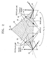
- FIG. 2 is a view for explaining the principle of Epipolar Geometry.
- Equation 1 is based on the Epipolar Geometry disclosed in a book entitled " Image Processing, Analysis and Machine Vision” (Sonka, V. Hlavac and R. Boyle, PWS Publishing, 1999, pp. 448-465 ).
- a focal point of a camera (not shown) photographing an object 28 in a space is disposed at a point 38 and an optical axis is set along a direction 30.
- the object 28 is projected on an image plane 34.
- u 1 f sx Y 1 ⁇ X 1
- v 1 f sy Y 1 ⁇ Z 1
- the unit of each of u 1 and v 1 is the number of pixels.
- the focal point of a camera photographing the object 28 in a space is disposed at another point 40 and an optical axis is set along a direction 32.
- the object 28 is projected on another image plane 36.
- the unit of each of u 2 and v 2 is the number of pixels.
- Equation 5 A conversion relationship between the coordinate systems ( 1 P 1 and 2 P 1 ) with respect to the same object is expressed in Equation 5.
- P 1 1 R 2 , 1 ⁇ P 1 2 + t 1 , 2 1
- Equation 5 can be expressed into Equation 6.
- Y 1 f sx ⁇ u 1 Y 1 Y 1 f sy ⁇ v 1 T R 2 , 1 ⁇ Y 2 f sx ⁇ u 2 Y 2 Y 2 f sy ⁇ v 2 T + t 1 , 2
- a matter of ego-motion estimation using the Epipolar Geometry refers to estimation of the linear movement amount (t 1, 2 ) and the matrix (R 2, 1 ) using the image coordinate values.
- constraints need to be used to remove a term for a coordinate value of the point P j in the space from Equation 6.
- the constraints are that the object P j in the space in FIG. 2 , Epipoles, and the projected objects 42 and 44 all must be present on an Epipolar plane 46 corresponding to a shaded portion in FIG. 2 . This can be expressed by Equation 7.
- Equation 7 is a final matrix to be obtained. Since the matrix Q has a size of 3 ⁇ 3, the number of equations to determine a normalized matrix satisfying Equation 7 is 8. This means that 8 or more matching points must be present in the space to calculate the matrix Q.
- the respective components of the matrix Q are obtained from equations to determine a normalized matrix satisfying Equation 7. This is disclosed in the book “ Image Processing, Analysis and Machine Vision” (Sonka, V. Hlavac and R. Boyle, PWS Publishing, 1999, pp. 466-476 ).
- Equation 8 A component of a vector ( 1 t 1, 2 ) can be calculated in advance through the linear movement amount (t 1, 2 ) obtained from Step 18.
- u 1 , 1 ⁇ f sx ⁇ a 1 ⁇ v 1 , 1 ⁇ f sy ⁇ R 2 , 1 ⁇ u 1 , 2 f sx ⁇ 1 ⁇ v 1 , 2 f sy T 0
- the rotational movement amount of the mobile device is determined only by considering a rotational component (Yaw) in a vertical direction with respect to the movement plane.
- Yaw rotational component
- the number of the minimum required matching points to obtain the normalized matrix (R 2,1 ) can be reduced to 2.
- the posture information of the mobile device is updated using the linear movement amount and the rotational movement amount (Step 22). That is, the posture information of the mobile device obtained previously, that is, information on the position Trs' and pose Rot' of the mobile device, is updated to a new posture information of the mobile device, that is, information on the position Trs and pose Rot of the mobile device, as shown in Equation 9.
- ⁇ Trs denotes a linear movement amount (t 1, 2 ) obtained from Step 18 and ⁇ Rot denotes the rotational movement amount obtained form Step 20.
- Step 24 whether the mobile device arrives at a target position is checked. If the mobile device does not arrive at the target position, the process goes back to Step 14. However, if the mobile device arrives at the target position, the method of using a rotational movement amount of a mobile device shown in FIG. 1 is terminated.
- the method of using a rotational movement amount of a mobile device shown in FIG. 1 may selectively include Steps 10, 12, 22, and 24. That is, the method shown in FIG. 1 may include merely Steps 14, 16, 18, and 20, but not Steps 10, 12, 22, and 24. Alternatively, the method shown in FIG. 1 may include merely Steps 14, 16, 18, 20, and 22, but not Steps 10, 12, and 24.
- a finally updated posture information can be obtained by repeatedly executing Step 14 through 22 until the mobile device arrives the target position.
- the posture information of the mobile device can be recognized through the finally updated posture information.
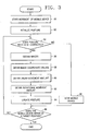
- FIG. 3 is a flow chart for explaining a method of using a rotational movement amount of a mobile device according to another embodiment of the present invention.
- the method includes the steps of initializing a mobile device (Steps 50 and 52), correcting (Steps 54, 56, 58, 60, 62, and 64), that is, updating, posture information when the posture information needs to be corrected, moving the mobile device when the posture information does not need to be corrected (Step 68), and determining whether the mobile device arrives at a target position (Step 66).
- Steps 50 and 52 of FIG. 3 are the same as those of Steps 10 and 12 of FIG. 1 and the functions of Steps 56-66 of FIG. 3 are the same as those of Step 14-24 of FIG. 1 , detailed descriptions on these steps are omitted. Accordingly, the method shown in FIG. 3 further includes Steps 54 and 68 compared to the method shown in FIG. 1 .
- Step 54 whether the posture information of the mobile device is to be corrected is determined (Step 54). For this, for example, whether a time for which the mobile device moves lapses a predetermined time can be determined.
- the predetermined time can be set by a user as a time period to correct posture information.
- Step 56 If it is determined that the posture information of the mobile device is to be corrected, the process goes to Step 56. If it is determined that the posture information of the mobile device does not need to be corrected, the mobile device is moved and the process goes to Step 66 (Step 68).
- a path formed two points may be a curve or straight line.
- the path formed by two points may be a straight line.
- FIG. 4 is a block diagram illustrating an apparatus for using a rotational movement amount of a mobile device according to an embodiment of the present invention.
- the apparatus includes an image obtaining portion 100, a coordinate value generating portion 102, a sensing portion 104, a movement amount generating portion 106, a posture information updating portion 108, a control portion 110, and a position checking portion 112.
- An apparatus plays the role of performing the method shown in FIG. 1 .
- Step 10 of FIG. 1 the control portion 110 generates a movement control signal and the generated movement control signal is output through an output port OUT1.
- the mobile device starts to move in response to the movement control signal.
- the control portion 110 and the posture information updating portion 108 perform Step 12. That is, the control portion 110 generates a posture information initialization signal and the generated posture information initialization signal is output through the posture information updating portion 108.
- the posture information updating portion 108 initializes the posture information, that is, information on the position and pose of the mobile device, in response to the posture information initialization signal output from the control portion 110.
- the image obtaining portion 100 obtains images at two different points on a path along which the mobile device moves and outputs the obtained images to the coordinate value generating portion 102. For example, when the initialization of the mobile device is recognized to be completed through the obtainment control signal, the image obtaining portion 100 obtains the two images.
- the image obtaining portion 100 may be at least one camera (not shown) attached to the mobile device. While moving with the mobile device, the camera obtains two images from two different points.
- the coordinate value generating portion 102 searches for matching points with respect to the obtained images, generates an image coordinate value of each matching point, and outputs the generated image coordinate value to the movement amount generating portion 106.
- the matching points found by the coordinate value generating portion 102 may correspond to the minimum required matching points.
- the sensing portion 104 and the movement amount generating portion 106 perform Step 18.
- the sensing portion 104 senses linear movement of the mobile device and outputs the sensed result to the movement amount generating portion 106.
- the sensing portion 104 may be a wheel encoder (not shown).
- the sensing portion 104 may be a linear accelerometer (not shown).
- the movement amount generating portion 106 generates a linear movement amount from the result sensed by the sensing portion 104 and outputs the generated linear movement amount to the posture information updating portion 108.
- the movement amount generating portion 106 generates a rotational movement amount from the generated linear movement amount and the image coordinate values output from the coordinate value generating portion 102, and outputs the generated rotational movement amount to the posture information updating portion 108.
- the posture information updating portion 108 updates the posture information of the mobile device from the rotational movement amount and the linear movement amount generated by the movement amount generating portion 106, and outputs the updated result through an output port OUT2.
- the position checking portion 112 in response to an update completion signal, checks whether the mobile device arrives at the target position and outputs the checked result to the image obtaining portion 100. That is, when the completion of the update of the posture information is recognized through the update completion signal output from the posture information updating portion 108, the position checking portion 112 checks whether the mobile device arrives at the target position.
- the image obtaining portion 100 obtains an image in response to the result checked by the position checking portion 112 (Step 14). That is, when it is recognized from the result of checking output from the position checking portion 112 that the mobile device does not arrive at the target position, two images at different two points on the path along which the mobile device moves are obtained.
- the apparatus shown in FIG. 3 may selectively adopt the posture information updating portion 108 and the position checking portion 112 and restrict the operation of the control portion 110 to selectively execute Steps 10 and 12.
- FIG. 5 is a block diagram illustrating an apparatus for using a rotational movement amount of a mobile device according to another embodiment of the present invention.
- the apparatus shown in FIG. 5 includes an image obtaining portion 150, a coordinate value generating portion 152, a sensing portion 154, a movement amount generating portion 156, a posture information updating portion 158, a correction checking portion 160, a control portion 162, and a position checking portion 164.
- the apparatus shown in FIG. 5 performs the method shown in FIG. 3 . Since the coordinate value generating portion 152, the sensing portion 154, the movement amount generating portion 156, and the posture information updating portion 158 shown in FIG. 5 have the same functions as those of the coordinate value generating portion 102, the sensing portion 104, the movement amount generating portion 106, and the posture information updating portion 108 shown in FIG. 4 , detailed descriptions thereof will be omitted.
- Step 50 the control portion 162 generates a movement control signal and outputs the generated movement control signal through an output port OUT3.
- the mobile device starts to move in response to the movement control signal.
- the control portion 162 and the posture information updating portion 158 execute Step 52.
- the control portion 162 generates a posture information initialization signal and outputs the generated posture information initialization signal to the posture information updating portion 158.
- the posture information updating portion 158 initializes posture information in response to the posture information initialization signal.
- Step 54 in response to a correction control signal generated by the control portion 162, the correction checking portion 160 checks whether to correct the posture information of the mobile device and outputs the result of checking to the image obtaining portion 150 and the control portion 162. For example, when the completion of the initialization of the mobile device is recognized through the correction control signal, the correction checking portion 160 starts to check whether to correct the posture information of the mobile device.
- the image obtaining portion 150 in response to the result of checking an output from the correction checking portion 160, obtains images and outputs the obtained images to the coordinate value generating portion 152. That is, when it is recognized from the result of checking output from the correction checking portion 160 that the posture information needs to be corrected, the image obtaining portion 150 obtains two images.
- the position checking portion 164 in response to an update completion signal output from the posture information updating portion 158, checks whether the mobile device arrives at the target position and outputs the result of checking to the correction checking portion 160. That is, if the it is recognized from the update completion signal that the updating of the posture information is completed, the position checking portion 164 checks whether the mobile device arrives the target position.
- the correction checking portion 160 in response to the result of checking by the position checking portion 164, checks whether the posture information is corrected. That is, if it is recognized from the result of checking by the position checking portion 164 that the mobile device does not arrived at the target position, the correction checking portion 160 checks whether to correct the posture information.
- Step 68 the control portion 162 generates a movement control signal in response to the result of checking by the correction checking portion 160. That is, if it is recognized from the result of checking by the correction checking portion 160 that the posture information does not need to be corrected, the control portion 162 generates the movement control signal to move the mobile device and outputs the movement control signal through the output port OUT3.
- the control portion 162 controls the position checking portion 164 so that the position checking portion 164 executes Step 66.
- a computer-readable recording medium for storing at least one computer program to control the above-described apparatus for using a rotational movement amount is described below.
- the computer program stored in a computer capable of reading a recording medium according to the present invention executes the steps of obtaining images at two different points on a path along which a mobile device moves, searching for matching points with respect to the obtained images and generating an image coordinate value of each matching point, generating a linear movement amount by sensing linear movement of the mobile device, and generating a rotational movement amount using the image coordinate values and the linear movement amount.
- the computer program may further execute a step of updating posture information of the mobile device using the linear movement amount and the rotational movement amount.
- the computer program stored on the recording medium may further execute a step of determining whether to correct the posture information of the mobile device. In this case, if it is determined that the posture information of the mobile device needs to be corrected, the process goes to the step of obtaining the images. Otherwise, the mobile device is moved.
- the method and apparatus for using a rotational movement amount of a mobile device and a computer-readable recording medium for storing a computer program according to the present invention can be applied to an self-running technology that is a core technology of a mobile robot, development of an environment recognition technology, an unmanned flying system, or an extremely cold or hot area expedition equipment.
- the method and apparatus for using a rotational movement amount of a mobile device and a computer-readable recording medium for storing a computer program according to the present invention through a chief structure consisting of the sensor 104 or 154 sensing the linear movement amount of the mobile device and the image obtaining portion 100 or 150 obtaining images, for example, a camera, estimate the rotational movement amount of the mobile device to locally recognize the posture information.
- a chief structure consisting of the sensor 104 or 154 sensing the linear movement amount of the mobile device and the image obtaining portion 100 or 150 obtaining images, for example, a camera.
- the present invention has an effect of high applicability in development of a self-running system in real time of a mobile device, for example, a robot.
Landscapes
- Engineering & Computer Science (AREA)
- Physics & Mathematics (AREA)
- Automation & Control Theory (AREA)
- Remote Sensing (AREA)
- Radar, Positioning & Navigation (AREA)
- General Physics & Mathematics (AREA)
- Aviation & Aerospace Engineering (AREA)
- Computer Vision & Pattern Recognition (AREA)
- Multimedia (AREA)
- Electromagnetism (AREA)
- Image Processing (AREA)
- Image Analysis (AREA)
- Length Measuring Devices By Optical Means (AREA)
- Control Of Position, Course, Altitude, Or Attitude Of Moving Bodies (AREA)
Claims (21)
- Verfahren zur Ermittlung eines Drehbewegungsbetrags einer mobilen Vorrichtung umfassend:Aufnehmen von Bildern an zwei verschiedenen Punkten auf einem Weg, entlang dem sich die mobile Vorrichtung bewegt,Suchen nach Übereinstimmungspunkten in Bezug auf die aufgenommenen Bilder und Ermitteln eines Bildkoordinatenwerts zu jedem der Übereinstimmungspunkte,gekennzeichnet durch die Schritte:Messen einer Linearbewegung der mobilen Vorrichtung und Ermitteln eines Linearbewegungsbetrags unter Verwendung eines Messergebnisses undErmitteln des Drehbewegungsbetrags unter Verwendung der Bildkoordinatenwerte und des Linearbewegungsbetrags.
- Verfahren nach Anspruch 1, ferner umfassend Aktualisieren von Lageinformation der mobilen Vorrichtung unter Verwendung des Linearbewegungsbetrags und des Drehbewegungsbetrags.
- Verfahren nach Anspruch 2, ferner umfassend Bestimmen, ob Lageinformation der mobilen Vorrichtung zu korrigieren ist, wobei die Bilder aufgenommen werden, wenn bestimmt ist, dass die Lageinformation der mobilen Vorrichtung korrigiert werden muss.
- Verfahren nach Anspruch 2, wobei die mobile Vorrichtung sich von einem Zeitpunkt, an dem der Bildkoordinatenwert ermittelt ist, bis die Lageinformation aktualisiert ist, bewegt.
- Verfahren nach Anspruch 3, wobei die mobile Vorrichtung von einem Zeitpunkt, an dem der Bildkoordinatenwert ermittelt ist, bis die Lageinformation aktualisiert ist, steht.
- Verfahren nach Anspruch 2 oder 3, ferner umfassend:Beginnen einer Bewegung der mobilen Vorrichtung,Initialisieren der Lageinformation der mobilen Vorrichtung und Übergang zum Aufnehmen der Bilder undBestimmen, ob die mobile Vorrichtung an einer Zielposition ankommt, nachdem die Lageinformation der mobilen Vorrichtung aktualisiert ist, und wenn bestimmt ist, dass die mobile Vorrichtung nicht an der Zielposition ankommt, Übergang zum Aufnehmen der Bilder.
- Verfahren nach Anspruch 3, ferner umfassend:Beginnen einer Bewegung der mobilen Vorrichtung,Initialisieren der Lageinformation der mobilen Vorrichtung und Übergang zum Bestimmen, ob die Lageinformation zu korrigieren ist, undBestimmen, ob die mobile Vorrichtung an einer Zielposition ankommt, nachdem die Lageinformation der mobilen Vorrichtung aktualisiert ist, und wenn bestimmt ist, dass die mobile Vorrichtung nicht an der Zielposition ankommt, Übergang zum Bestimmen, ob die Lageinformation zu korrigieren ist.
- Verfahren nach Anspruch 7, ferner umfassend Bewegen der mobilen Vorrichtung und Übergang zum Bestimmen, ob die mobile Vorrichtung an der Zielposition ankommt, wenn bestimmt ist, dass die Lageinformation der mobilen Vorrichtung nicht korrigiert werden muss.
- Verfahren nach einem der vorhergehenden Ansprüche, wobei ein Intervall zwischen den beiden Punkt eng festgesetzt wird.
- Verfahren nach einem der vorhergehenden Ansprüche, wobei die Anzahl an Übereinstimmungspunkten 8 beträgt, was eine minimale Anzahl an erforderlichen Übereinstimmungspunkten ist.
- Verfahren nach Anspruch 1, wobei die Anzahl an Übereinstimmungspunkten 2 beträgt, was eine minimale Anzahl an erforderlichen Übereinstimmungspunkten ist.
- Verfahren nach Anspruch 10, wobei die Anzahl an Übereinstimmungspunkten so festgesetzt wird, dass sie ein ganzzahliges Vielfaches der minimalen Anzahl an erforderlichen Übereinstimmungspunkten ist.
- Verfahren nach Anspruch 3, wobei der durch die zwei Punkte gebildete Weg eine gerade Linie ist.
- Verfahren nach Anspruch 1, wobei der Drehbewegungsbetrag der mobilen Vorrichtung unter Verwendung einer Konversionsmatrix (R1, 2) ermittelt wird, die ermittelt wird aus

wobei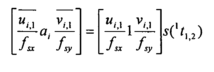
1 die minimale Anzahl an erforderlichen Übereinstimmungspunkten bezeichnet, t1,2 einen Linearbewegungsbetrag bezeichnet und 1t1,2 einen Linearbewegungsbetrag bezeichnet, der in einem ersten Koordinatensystem 1 ausgedrückt ist, ui,2, ui,1, vi,1 und vi,2 die Bildkoordinatenwerte bezeichnen, s() eine schiefsymmetrische Matrix bezeichnet, die so definiert ist, dass sie die Kreuzproduktberechnung eines Vektors ausdrückt, R2, 1 eine inverse Matrix zu R1, 2 ist,

- Vorrichtung zur Ermittlung eines Drehbewegungsbetrags einer mobilen Vorrichtung umfassend:einen Bildaufnahmeteil, der Bilder an zwei verschiedenen Punkten auf einem Weg aufnimmt, entlang dem sich die mobile Vorrichtung bewegt,einen Koordinatenwerterzeugungsteil, der nach Übereinstimmungspunkten in Bezug auf die aufgenommenen Bilder sucht und einen Bildkoordinatenwert zu jedem der Übereinstimmungspunkte erzeugt,gekennzeichnet durch:einen Messteil, der Linearbewegung der mobilen Vorrichtung misst, undeinen Bewegungsbetragerzeugungsteil, der einen Linearbewegungsbetrag aus einem Ergebnis der Messung erzeugt und den Drehbewegungsbetrag aus den Bildkoordinatenwerten und dem Linearbewegungsbetrag erzeugt.
- Vorrichtung nach Anspruch 15, ferner umfassend einen Lageinformationsaktualisierungsteil, der Lageinformation der mobilen Vorrichtung aus dem Linearbewegungsbetrag und dem Drehbewegungsbetrag, die vom Bewegungsbetragerzeugungsteil erzeugt sind, aktualisiert und ein aktualisiertes Ergebnis ausgibt.
- Vorrichtung nach Anspruch 16, ferner umfassend einen Korrekturprüfteil, der prüft, ob die Lageinformation der mobilen Vorrichtung zu korrigieren ist, wobei der Bildaufnahmeteil die Bilder in Abhängigkeit vom Prüfergebnis aufnimmt.
- Vorrichtung nach Anspruch 16, ferner umfassend:einen Steuerteil, der ein Bewegungssteuersignal, ein Lageinformationsinitialisierungssignal und ein Aufnahmesteuersignal erzeugt, undeinen Positionsprüfteil, der in Abhängigkeit von einem Aktualisierungsabschlusssignal, das den Abschluss einer Aktualisierung angibt und vom Lageinformationsaktualisierungsteil empfangen wird, prüft, ob die mobile Vorrichtung an einer Zielposition ankommt,wobei die mobile Vorrichtung sich in Abhängigkeit vom Bewegungssteuersignal bewegt, der Lageinformationsaktualisierungsteil die Lageinformation in Abhängigkeit vom Lageinformationsinitialisierungssignal initialisiert und der Bildaufnahmeteil das Bild in Abhängigkeit vom Aufnahmesteuersignal und einem Ergebnis der Prüfung durch den Positionsprüfteil aufnimmt.
- Vorrichtung nach Anspruch 17, ferner umfassend:einen Steuerteil, der ein Bewegungssteuersignal, ein Lageinformationsinitialisierungssignal und ein Korrektursteuersignal erzeugt, undeinen Positionsprüfteil, der in Abhängigkeit von einem Aktualisierungsabschlusssignal, das den Abschluss einer Aktualisierung angibt und vom Lageinformationsaktualisierungsteil empfangen wird, prüft, ob die mobile Vorrichtung an einer Zielposition ankommt,wobei die mobile Vorrichtung sich in Abhängigkeit vom Bewegungssteuersignal bewegt, der Lageinformationsaktualisierungsteil die Lageinformation in Abhängigkeit vom Lageinformationsinitialisierungssignal initialisiert und der Korrekturprüfteil in Abhängigkeit vom Korrektursteuersignal oder einem Prüfergebnis, das vom Positionsprüfteil erhalten wird, prüft, ob die Lageinformation zu korrigieren ist.
- Vorrichtung nach Anspruch 19, wobei der Steuerteil das Bewegungssteuersignal in Abhängigkeit vom Prüfergebnis des Korrekturprüfteils erzeugt und einen Prüfvorgang des Positionsprüfteils steuert.
- Computerlesbares Aufzeichnungsmedium, das mindestens ein Computerprogramm speichert, um unter Verwendung eines Drehbewegungsbetrags einer mobilen Vorrichtung ein Gerät zu steuern, wobei ein Verfahren nach einem der Ansprüche 1 bis 14 ausgeführt wird.
Applications Claiming Priority (2)
| Application Number | Priority Date | Filing Date | Title |
|---|---|---|---|
| KR1020030095522A KR100543709B1 (ko) | 2003-12-23 | 2003-12-23 | 이동체의 회전 이동량 이용 방법과 장치 및 컴퓨터프로그램을 저장하는 컴퓨터로 읽을 수 있는 기록 매체 |
| KR2003095522 | 2003-12-23 |
Publications (3)
| Publication Number | Publication Date |
|---|---|
| EP1548534A2 EP1548534A2 (de) | 2005-06-29 |
| EP1548534A3 EP1548534A3 (de) | 2006-11-29 |
| EP1548534B1 true EP1548534B1 (de) | 2008-06-25 |
Family
ID=34545900
Family Applications (1)
| Application Number | Title | Priority Date | Filing Date |
|---|---|---|---|
| EP04254937A Expired - Lifetime EP1548534B1 (de) | 2003-12-23 | 2004-08-17 | Verfahren und Gerät zur Verwendung einer Drehbewegungsmenge einer mobilen Vorrichtung und computerlesbares Speichermedium zum Speichern eines Computerprogrammes |
Country Status (6)
| Country | Link |
|---|---|
| US (1) | US7747348B2 (de) |
| EP (1) | EP1548534B1 (de) |
| JP (1) | JP4171459B2 (de) |
| KR (1) | KR100543709B1 (de) |
| CN (1) | CN100394340C (de) |
| DE (1) | DE602004014586D1 (de) |
Families Citing this family (22)
| Publication number | Priority date | Publication date | Assignee | Title |
|---|---|---|---|---|
| DE102005058312A1 (de) * | 2005-12-07 | 2007-06-14 | Dürr Ecoclean GmbH | Greifvorrichtung für einen Roboter oder einen Portallader |
| US7459624B2 (en) | 2006-03-29 | 2008-12-02 | Harmonix Music Systems, Inc. | Game controller simulating a musical instrument |
| US20090075711A1 (en) | 2007-06-14 | 2009-03-19 | Eric Brosius | Systems and methods for providing a vocal experience for a player of a rhythm action game |
| US8678896B2 (en) | 2007-06-14 | 2014-03-25 | Harmonix Music Systems, Inc. | Systems and methods for asynchronous band interaction in a rhythm action game |
| US20110130940A1 (en) * | 2008-05-23 | 2011-06-02 | Foundacion Fatronik | Wheelchair and method for correcting the guidance of a wheelchair |
| WO2010006054A1 (en) | 2008-07-08 | 2010-01-14 | Harmonix Music Systems, Inc. | Systems and methods for simulating a rock and band experience |
| US8465366B2 (en) | 2009-05-29 | 2013-06-18 | Harmonix Music Systems, Inc. | Biasing a musical performance input to a part |
| US8449360B2 (en) | 2009-05-29 | 2013-05-28 | Harmonix Music Systems, Inc. | Displaying song lyrics and vocal cues |
| WO2011056657A2 (en) | 2009-10-27 | 2011-05-12 | Harmonix Music Systems, Inc. | Gesture-based user interface |
| US9981193B2 (en) | 2009-10-27 | 2018-05-29 | Harmonix Music Systems, Inc. | Movement based recognition and evaluation |
| US8550908B2 (en) | 2010-03-16 | 2013-10-08 | Harmonix Music Systems, Inc. | Simulating musical instruments |
| WO2011155958A1 (en) | 2010-06-11 | 2011-12-15 | Harmonix Music Systems, Inc. | Dance game and tutorial |
| US9358456B1 (en) | 2010-06-11 | 2016-06-07 | Harmonix Music Systems, Inc. | Dance competition game |
| US8562403B2 (en) | 2010-06-11 | 2013-10-22 | Harmonix Music Systems, Inc. | Prompting a player of a dance game |
| US9024166B2 (en) | 2010-09-09 | 2015-05-05 | Harmonix Music Systems, Inc. | Preventing subtractive track separation |
| CN103777872A (zh) * | 2012-10-24 | 2014-05-07 | 中国电信股份有限公司 | 移动终端及其解锁方法 |
| KR101891980B1 (ko) * | 2012-12-11 | 2018-08-27 | 한국전자통신연구원 | 회전체의 회전 특성 측정 방법 및 장치 |
| CN104162894B (zh) * | 2013-05-17 | 2016-03-02 | 光宝电子(广州)有限公司 | 清扫机器人及清扫机器人的定位方法 |
| CN104552341B (zh) * | 2014-12-29 | 2016-05-04 | 国家电网公司 | 移动工业机器人单点多视角挂表位姿误差检测方法 |
| CN105072402B (zh) * | 2015-08-11 | 2017-11-28 | 余路 | 一种机器人巡视监测的方法 |
| WO2019138640A1 (ja) * | 2018-01-10 | 2019-07-18 | ソニー株式会社 | 情報処理装置、情報処理方法、および、プログラム |
| US11029698B2 (en) * | 2018-04-17 | 2021-06-08 | AI Incorporated | Method for tracking movement of a mobile robotic device |
Family Cites Families (26)
| Publication number | Priority date | Publication date | Assignee | Title |
|---|---|---|---|---|
| JPH03290800A (ja) | 1990-04-06 | 1991-12-20 | Hitachi Ltd | 自走車のナビゲーションシステム |
| CN1141427A (zh) * | 1995-12-29 | 1997-01-29 | 西安交通大学 | 基于图像识别的运动物体测量方法 |
| US5950020A (en) * | 1997-01-22 | 1999-09-07 | Polaroid Corporation | Folding photographic method and apparatus |
| AUPP299498A0 (en) * | 1998-04-15 | 1998-05-07 | Commonwealth Scientific And Industrial Research Organisation | Method of tracking and sensing position of objects |
| US6292171B1 (en) * | 1999-03-31 | 2001-09-18 | Seiko Epson Corporation | Method and apparatus for calibrating a computer-generated projected image |
| JP4028135B2 (ja) * | 1999-05-27 | 2007-12-26 | 本田技研工業株式会社 | 物体検出装置 |
| US7050606B2 (en) * | 1999-08-10 | 2006-05-23 | Cybernet Systems Corporation | Tracking and gesture recognition system particularly suited to vehicular control applications |
| JP3760068B2 (ja) * | 1999-12-02 | 2006-03-29 | 本田技研工業株式会社 | 画像認識装置 |
| JP2003016429A (ja) * | 2001-06-28 | 2003-01-17 | Honda Motor Co Ltd | 車両周辺監視装置 |
| JP2003178309A (ja) | 2001-10-03 | 2003-06-27 | Toyota Central Res & Dev Lab Inc | 移動量推定装置 |
| JP3764086B2 (ja) * | 2001-10-29 | 2006-04-05 | 本田技研工業株式会社 | 車両用情報提供装置 |
| KR100837776B1 (ko) | 2001-12-24 | 2008-06-13 | 주식회사 케이티 | 2차원 영상을 3차원 영상으로 변환하는 영상 변환 장치 및그 방법 |
| JP3756452B2 (ja) * | 2002-01-18 | 2006-03-15 | 本田技研工業株式会社 | 赤外線画像処理装置 |
| JP3983573B2 (ja) * | 2002-03-06 | 2007-09-26 | 富士重工業株式会社 | ステレオ画像特性検査システム |
| CN101763118B (zh) * | 2002-03-18 | 2015-09-02 | 索尼株式会社 | 机器人设备及其动作控制方法 |
| US20040068416A1 (en) * | 2002-04-22 | 2004-04-08 | Neal Solomon | System, method and apparatus for implementing a mobile sensor network |
| EP1510896B1 (de) * | 2002-05-31 | 2016-03-09 | Fujitsu Limited | Ferngesteuerter roboter und roboter-selbstpositionsidentifizierungsverfahren |
| CA2633137C (en) * | 2002-08-13 | 2012-10-23 | The Governors Of The University Of Calgary | Microsurgical robot system |
| EP1398601A3 (de) * | 2002-09-13 | 2014-05-07 | Canon Kabushiki Kaisha | Head-up-Anzeige für Navigationszwecke in einem Fahrzeug |
| JP3902109B2 (ja) * | 2002-10-02 | 2007-04-04 | 本田技研工業株式会社 | 赤外線カメラ特性確認治具 |
| WO2004033160A1 (ja) * | 2002-10-10 | 2004-04-22 | Sony Corporation | ロボット装置の動作制御装置及び動作制御方法 |
| WO2004059900A2 (en) * | 2002-12-17 | 2004-07-15 | Evolution Robotics, Inc. | Systems and methods for visual simultaneous localization and mapping |
| JP3987048B2 (ja) * | 2003-03-20 | 2007-10-03 | 本田技研工業株式会社 | 車両周辺監視装置 |
| US8896660B2 (en) * | 2003-05-30 | 2014-11-25 | Alcatel Lucent | Method and apparatus for computing error-bounded position and orientation of panoramic cameras in real-world environments |
| JP3987013B2 (ja) * | 2003-09-01 | 2007-10-03 | 本田技研工業株式会社 | 車両周辺監視装置 |
| KR200354360Y1 (ko) | 2004-03-31 | 2004-06-23 | 주식회사 씨플러스 | 대차 탑재형 이동식 방수포 |
-
2003
- 2003-12-23 KR KR1020030095522A patent/KR100543709B1/ko not_active Expired - Fee Related
-
2004
- 2004-08-17 EP EP04254937A patent/EP1548534B1/de not_active Expired - Lifetime
- 2004-08-17 DE DE602004014586T patent/DE602004014586D1/de not_active Expired - Fee Related
- 2004-09-08 US US10/935,592 patent/US7747348B2/en not_active Expired - Fee Related
- 2004-12-14 CN CNB2004101021088A patent/CN100394340C/zh not_active Expired - Fee Related
- 2004-12-24 JP JP2004372414A patent/JP4171459B2/ja not_active Expired - Fee Related
Also Published As
| Publication number | Publication date |
|---|---|
| KR20050065710A (ko) | 2005-06-30 |
| CN100394340C (zh) | 2008-06-11 |
| CN1637675A (zh) | 2005-07-13 |
| EP1548534A2 (de) | 2005-06-29 |
| JP4171459B2 (ja) | 2008-10-22 |
| EP1548534A3 (de) | 2006-11-29 |
| DE602004014586D1 (de) | 2008-08-07 |
| JP2005182834A (ja) | 2005-07-07 |
| US7747348B2 (en) | 2010-06-29 |
| US20050137750A1 (en) | 2005-06-23 |
| KR100543709B1 (ko) | 2006-01-20 |
Similar Documents
| Publication | Publication Date | Title |
|---|---|---|
| US7747348B2 (en) | Method and apparatus for using rotational movement amount of mobile device and computer-readable recording medium for storing computer program | |
| US12529563B2 (en) | Vision-aided inertial navigation | |
| CN109991636B (zh) | 基于gps、imu以及双目视觉的地图构建方法及系统 | |
| CN107741234B (zh) | 一种基于视觉的离线地图构建及定位方法 | |
| CN111220153B (zh) | 基于视觉拓扑节点和惯性导航的定位方法 | |
| CN114526745A (zh) | 一种紧耦合激光雷达和惯性里程计的建图方法及系统 | |
| EP2460059B1 (de) | Einschätzung der Positionen einer Vorrichtung und mindestens eines Zieles in einer Umgebung | |
| US9122278B2 (en) | Vehicle navigation | |
| CN107402012A (zh) | 一种车辆的组合导航方法 | |
| CN110763224A (zh) | 一种自动导引运输车导航方法及导航系统 | |
| Ivanjko et al. | Extended Kalman filter based mobile robot pose tracking using occupancy grid maps | |
| KR100864801B1 (ko) | 이동로봇에서 홈포지셔닝을 이용한 오도메트리 보정 방법 | |
| CN112837352A (zh) | 基于图像的数据处理方法、装置及设备、汽车、存储介质 | |
| AU2012260626A1 (en) | Vehicle navigation | |
| Antonelli et al. | Linear estimation of the physical odometric parameters for differential-drive mobile robots | |
| CN118603077A (zh) | 一种基于多传感器融合的四足机器人巡检地图构建系统及方法 | |
| JP7594691B2 (ja) | 自動運転および/または支援運転のための駆動装置、車両、および方法 | |
| CN112556681B (zh) | 一种基于视觉的果园机械导航定位方法 | |
| EP2527943A1 (de) | Fahrzeugnavigation | |
| CN116794640B (zh) | 一种可移动载体的LiDAR-GPS/IMU自标定方法 | |
| CN117928553A (zh) | 基于误差扩展卡尔曼滤波器的多源融合定位方法及系统 | |
| EP2287698A1 (de) | Einschätzung der Positionen einer Vorrichtung und mindestens eines Zieles in einer Umgebung | |
| Baer et al. | EgoMaster: A central ego motion estimation for driver assist systems | |
| US12625504B2 (en) | Autonomous mobile device and control method thereof | |
| TW202134151A (zh) | 載具即時精準位置校正系統 |
Legal Events
| Date | Code | Title | Description |
|---|---|---|---|
| PUAI | Public reference made under article 153(3) epc to a published international application that has entered the european phase |
Free format text: ORIGINAL CODE: 0009012 |
|
| AK | Designated contracting states |
Kind code of ref document: A2 Designated state(s): AT BE BG CH CY CZ DE DK EE ES FI FR GB GR HU IE IT LI LU MC NL PL PT RO SE SI SK TR |
|
| AX | Request for extension of the european patent |
Extension state: AL HR LT LV MK |
|
| PUAL | Search report despatched |
Free format text: ORIGINAL CODE: 0009013 |
|
| AK | Designated contracting states |
Kind code of ref document: A3 Designated state(s): AT BE BG CH CY CZ DE DK EE ES FI FR GB GR HU IE IT LI LU MC NL PL PT RO SE SI SK TR |
|
| AX | Request for extension of the european patent |
Extension state: AL HR LT LV MK |
|
| 17P | Request for examination filed |
Effective date: 20070321 |
|
| AKX | Designation fees paid |
Designated state(s): DE FR GB NL |
|
| GRAP | Despatch of communication of intention to grant a patent |
Free format text: ORIGINAL CODE: EPIDOSNIGR1 |
|
| GRAS | Grant fee paid |
Free format text: ORIGINAL CODE: EPIDOSNIGR3 |
|
| GRAA | (expected) grant |
Free format text: ORIGINAL CODE: 0009210 |
|
| AK | Designated contracting states |
Kind code of ref document: B1 Designated state(s): DE FR GB NL |
|
| REG | Reference to a national code |
Ref country code: GB Ref legal event code: FG4D |
|
| REF | Corresponds to: |
Ref document number: 602004014586 Country of ref document: DE Date of ref document: 20080807 Kind code of ref document: P |
|
| PG25 | Lapsed in a contracting state [announced via postgrant information from national office to epo] |
Ref country code: NL Free format text: LAPSE BECAUSE OF FAILURE TO SUBMIT A TRANSLATION OF THE DESCRIPTION OR TO PAY THE FEE WITHIN THE PRESCRIBED TIME-LIMIT Effective date: 20080625 |
|
| NLV1 | Nl: lapsed or annulled due to failure to fulfill the requirements of art. 29p and 29m of the patents act | ||
| PGFP | Annual fee paid to national office [announced via postgrant information from national office to epo] |
Ref country code: FR Payment date: 20081112 Year of fee payment: 5 |
|
| PLBE | No opposition filed within time limit |
Free format text: ORIGINAL CODE: 0009261 |
|
| STAA | Information on the status of an ep patent application or granted ep patent |
Free format text: STATUS: NO OPPOSITION FILED WITHIN TIME LIMIT |
|
| PGFP | Annual fee paid to national office [announced via postgrant information from national office to epo] |
Ref country code: DE Payment date: 20081103 Year of fee payment: 5 |
|
| 26N | No opposition filed |
Effective date: 20090326 |
|
| PGFP | Annual fee paid to national office [announced via postgrant information from national office to epo] |
Ref country code: GB Payment date: 20081105 Year of fee payment: 5 |
|
| GBPC | Gb: european patent ceased through non-payment of renewal fee |
Effective date: 20090817 |
|
| REG | Reference to a national code |
Ref country code: FR Ref legal event code: ST Effective date: 20100430 |
|
| PG25 | Lapsed in a contracting state [announced via postgrant information from national office to epo] |
Ref country code: DE Free format text: LAPSE BECAUSE OF NON-PAYMENT OF DUE FEES Effective date: 20100302 Ref country code: FR Free format text: LAPSE BECAUSE OF NON-PAYMENT OF DUE FEES Effective date: 20090831 |
|
| PG25 | Lapsed in a contracting state [announced via postgrant information from national office to epo] |
Ref country code: GB Free format text: LAPSE BECAUSE OF NON-PAYMENT OF DUE FEES Effective date: 20090817 |