EP1548489A1 - Progressive power contact lenses having an opaque ring in the transition region - Google Patents
Progressive power contact lenses having an opaque ring in the transition region Download PDFInfo
- Publication number
- EP1548489A1 EP1548489A1 EP04257891A EP04257891A EP1548489A1 EP 1548489 A1 EP1548489 A1 EP 1548489A1 EP 04257891 A EP04257891 A EP 04257891A EP 04257891 A EP04257891 A EP 04257891A EP 1548489 A1 EP1548489 A1 EP 1548489A1
- Authority
- EP
- European Patent Office
- Prior art keywords
- lens
- power
- ring
- transition region
- distance
- Prior art date
- Legal status (The legal status is an assumption and is not a legal conclusion. Google has not performed a legal analysis and makes no representation as to the accuracy of the status listed.)
- Granted
Links
- 230000000750 progressive effect Effects 0.000 title claims abstract description 28
- 230000007704 transition Effects 0.000 title claims description 26
- 230000004438 eyesight Effects 0.000 claims description 21
- 208000001491 myopia Diseases 0.000 claims description 21
- 238000000034 method Methods 0.000 claims description 12
- 239000000463 material Substances 0.000 claims description 5
- 230000005540 biological transmission Effects 0.000 claims description 4
- 239000011248 coating agent Substances 0.000 claims description 3
- 238000000576 coating method Methods 0.000 claims description 3
- 238000000465 moulding Methods 0.000 claims description 3
- 238000007639 printing Methods 0.000 claims description 3
- 238000005530 etching Methods 0.000 claims description 2
- 238000004519 manufacturing process Methods 0.000 claims description 2
- 238000000151 deposition Methods 0.000 claims 1
- 210000001747 pupil Anatomy 0.000 description 12
- 230000003287 optical effect Effects 0.000 description 5
- 230000000694 effects Effects 0.000 description 3
- 201000010041 presbyopia Diseases 0.000 description 3
- 238000010586 diagram Methods 0.000 description 2
- 239000011347 resin Substances 0.000 description 2
- 229920005989 resin Polymers 0.000 description 2
- 230000000007 visual effect Effects 0.000 description 2
- 206010027646 Miosis Diseases 0.000 description 1
- 230000006835 compression Effects 0.000 description 1
- 238000007906 compression Methods 0.000 description 1
- 238000007796 conventional method Methods 0.000 description 1
- 230000003247 decreasing effect Effects 0.000 description 1
- 230000008021 deposition Effects 0.000 description 1
- 238000007516 diamond turning Methods 0.000 description 1
- 239000007788 liquid Substances 0.000 description 1
- 238000007649 pad printing Methods 0.000 description 1
- 230000008447 perception Effects 0.000 description 1
- 239000000049 pigment Substances 0.000 description 1
- 230000004304 visual acuity Effects 0.000 description 1
Images


Classifications
-
- G—PHYSICS
- G02—OPTICS
- G02C—SPECTACLES; SUNGLASSES OR GOGGLES INSOFAR AS THEY HAVE THE SAME FEATURES AS SPECTACLES; CONTACT LENSES
- G02C7/00—Optical parts
- G02C7/02—Lenses; Lens systems ; Methods of designing lenses
- G02C7/04—Contact lenses for the eyes
- G02C7/041—Contact lenses for the eyes bifocal; multifocal
- G02C7/044—Annular configuration, e.g. pupil tuned
-
- G—PHYSICS
- G02—OPTICS
- G02C—SPECTACLES; SUNGLASSES OR GOGGLES INSOFAR AS THEY HAVE THE SAME FEATURES AS SPECTACLES; CONTACT LENSES
- G02C7/00—Optical parts
- G02C7/02—Lenses; Lens systems ; Methods of designing lenses
- G02C7/04—Contact lenses for the eyes
-
- G—PHYSICS
- G02—OPTICS
- G02C—SPECTACLES; SUNGLASSES OR GOGGLES INSOFAR AS THEY HAVE THE SAME FEATURES AS SPECTACLES; CONTACT LENSES
- G02C7/00—Optical parts
- G02C7/02—Lenses; Lens systems ; Methods of designing lenses
- G02C7/06—Lenses; Lens systems ; Methods of designing lenses bifocal; multifocal ; progressive
-
- G—PHYSICS
- G02—OPTICS
- G02C—SPECTACLES; SUNGLASSES OR GOGGLES INSOFAR AS THEY HAVE THE SAME FEATURES AS SPECTACLES; CONTACT LENSES
- G02C7/00—Optical parts
- G02C7/16—Shades; shields; Obturators, e.g. with pinhole, with slot
Definitions
- the invention relates to ophthalmic lenses.
- the invention provides lenses that use more than one optical power, or focal length, and are useful in the correction of presbyopia.
- the eye is less able to accommodate, or bend the natural lens, to focus on objects that are relatively near to the observer. This condition is known as presbyopia. Additionally, for persons who have had their natural lens removed and an intraocular lens inserted as a replacement, the ability to accommodate is totally absent.
- the mono-vision system in which a person is fitted with one contact lens for distance vision and one lens for near vision.
- the mono-vision system permits the lens wearer to distinguish both distance and near objects, but is disadvantageous in that a substantial loss in depth perception results.
- the optic zone of each lens of a lens pair is provided with more than one power.
- the optic zone may have both distance and near power, which the eye uses simultaneously. Neither of these methods provides good results in terms of visual acuity and lens wearer satisfaction.
- Lenses in which the power progressively and continuously changes from near to distance or distance to near vision power have been proposed. These lenses are advantageous in that they distribute light from viewed distant to near objects in a smooth fashion. However, when these lenses move on the eye so that the lens is not aligned with the center of the lens wearer's line of sight, visual artifacts, or ghosting of the image, results.
- ghosting is meant that the object being viewed through the lens along with a faint image of the object is seen by the lens wearer.
- the invention provides methods for designing lenses useful for correcting presbyopia, lenses incorporating such designs, and methods for producing these lenses.
- the lenses are advantageous in that a progressive design is utilized in which ghosting of images is minimized or eliminated. Additionally, the lens' performance on eye is more predictable than other progressive multifocal designs.
- the invention provides a contact lens comprising, consisting essentially of, and consisting of an optic zone having a progressive power zone comprising, consisting essentially of, and consisting of a distance vision power region, a near vision power region and a transition region therebetween, wherein a substantially opaque annular ring obscures light transmission through the transition region.
- progressive power zone means a continuous, aspheric zone having a distance vision power region and a near vision power region, and a transition region of increasing or decreasing dioptric power connecting the distance and near regions.
- distance vision power region is meant a region having an amount of refractive power required to correct the lens wearer's distance vision acuity to the desired degree.
- near vision power region is meant a region having an amount of refractive power required to correct the wearer's near vision acuity to the desired degree.
- a substantially opaque annular ring overlies the transition region.
- substantially opaque is meant that the opacity of the annular ring is about 75 to about 100 %, meaning that 75 to 100 % of incident light is absorbed.
- the amount of opacity used for the ring will depend upon a balancing of the desired visual result from use of the ring with the loss of light that results from increasing opacity. In the lenses of the invention, a range of opacity of about 75 to about 95 % is preferred.
- the dimension of the ring is such that it substantially corresponds to, or is slightly larger than, the dimensions of the transition region.
- the transition region will be about 0.7 to about 1.2 mm in diameter and, thus, the ring will be about 0.7 to about 1.2 mm, preferably 0.95 to about 1.15 mm in diameter.
- the diameter of the annular ring is such that, in no instance is the ring greater than the lens wearer's pupil regardless of lighting conditions.
- the opacity of the ring may itself be progressive meaning that the opacity increase as one moves from the periphery of the ring towards its innermost edge.
- the opaque ring may be provided by coating or printing the ring onto a surface of the lens by any convenient method. Suitable tints and pigments useful in coating or printing the ring are well known in the art.
- the opaque ring may be deposited onto the desired portion of the molding surface of a lens mold.
- molding surface is meant the surface of a mold or mold half used to form a surface of a lens.
- the deposition is carried out by pad printing by known methods.
- the ring may be provided by incorporating a ring-shaped layer of material within the lens material.
- the lens surface may be disrupted as, for example, by etching to provide the opaque ring.
- Lens 10 has a central region 11, which is a near vision power region, a transition region (not shown), annular ring 12 overlying the transition region, distance vision power region 13, and non-optical, lenticular region 14.
- Annular ring 12 has a periphery 15 and an innermost edge 16. Operation of the lens is demonstrated as follows.
- Figure 2 shows a spot diagram produced using ZEMAXTM raytrace design software.
- An eye and a lens having progressive power was modeled and a pattern of rays for a 2 mm aperture pupil was traced through them.
- the lens diameter was 14.4 mm and the entire optic zone diameter was 8 mm.
- the 2 mm aperture pupil was selected to provide a high luminance, or small pupil, model.
- the rays are seen as crosses 22 along with pupil 23 and near image 24.
- the lens is decentered upwardly by approximately 1000 ⁇ m and tilted 7 degrees, meaning that the superior portion of the lens tilts toward the eye so that an angle of 7 degrees is formed between that portion of the lens and the original position, or the zero degree position when gazing straight through, of the lens on the eye.
- the near image is formed at the top and is surrounded by a number of crosses indicating that there is significant transition and distance region energy close to the near image, which energy will cause the lens wearer to see a ghost image.
- Figure 3 is shown the effect of adding a ring with approximately 100 % opacity, which ring overlies the transition region of the lens of Example 2.
- the midpoint of the transition region was about 1.0 mm from the center of the lens.
- the opaque ring begins at a diameter of about 0.9 mm and ends at about 1.12 mm.
- no distance and transition region energy is close to the near image 34 indicating that the lens wearer will not see a ghosted image.
- Figure 4 shows a spot diagram for a 3.5 mm aperture pupil.
- the overall lens diameter was 14.4 mm with an 8 mm diameter optic zone.
- the lens is decentered upwardly approximately 500 ⁇ m and tilted 2.75 degrees toward the eye's surface.
- the near image is formed at the top and is surrounded by a number of crosses indicating that there is significant transition and distance region energy close to the near image, which energy will cause the lens wearer to see a ghost image.
- Figure 5 is shown the effect of adding a ring with a approximately 100 % opacity over the transition region of a lens similar to the lens of Figure 4, except that the aperture is 3.75 mm.
- the change in aperture was made to determine the effect of the system in conditions of dim light in which the pupil enlarges.
- the midpoint of the transition region was about 1.0 mm from the lens' center and the opaque ring begins at about 0.9 mm and ends at about 1.12 mm.
- no distance and transition region energy is close to the near image 54 indicating that the lens wearer will not see a ghosted image.
- n is the variable that controls the slope of the progression from near to distance vision power and distance to near vision power in the lens. The less the value of n, the more gradual the progression will be.
- a position, an amplitude, and a width for the progressive power zone is determined by the following equation: wherein:
- position is meant the power zone position in reference to the pupil.
- amplitude is meant the extent or range of the power progression within the power zone.
- the rate of change and contour of the power change from distance to near and near to distance vision power is varied.
- P is determined as follows.
- the maximum and minimum pupil diameters are selected along with interval steps from the minimum to the maximum.
- the interval steps selected are at the designers discretion, but preferably are suitable to facilitate production of the lens as, for example, by computer numerical controlled lathe. From the maximum diameter, the percentage of total diameter P is defined.
- Equation V is used for center distance lens designs meaning that the distance vision power is in the center of the optic zone and the near vision power is at the optic zone's periphery.
- Equation VI is used for center near lens designs, or lenses in which the near vision power is in the center and the distance vision is at the periphery.
- * A and Power
- t is determined by selection of the maximum and minimum pupil diameters.
- the minimum diameter is assigned a value of 90 degrees and the maximum diameter of 180 degrees, in linear intervals.
- Equation VII is used for center distance designs and Equation VIII is used for center near lenses.
- * A and Power
- the designs of the invention are useful in producing contact lenses that are hard or soft lenses.
- Soft contact lenses made of any material suitable for producing such lenses, preferably are used.
- the lenses of the invention may have any of a variety of corrective optical characteristics incorporated onto the surfaces in addition to distance and near optical powers, such as, for example, cylinder power.
- the progressive power zone may be on the object-side, or front, surface, the eye-side, or back, surface, or both surfaces.
- the progressive power zone has at least two regions of differing power, distance and near vision power, and preferably three regions, distance, near, and intermediate vision power.
- Intermediate power may be supplied as a consequence of the power progression between the peak of the power of the near and distance vision regions.
- a region of intermediate power may also be designed, as for example by using Equation I.
- the progressive power zone is preferably rotationally symmetric.
- the distance, near, and intermediate powers are spherical or toric powers. Additionally, the distance, near, and intermediate optical power regions may be of any desired and practical dimensions.
- the lenses of the invention may be formed by any conventional method.
- the progressive power zones formed therein may be produced by diamond-turning using differing radii.
- the zones may be diamond-turned into the molds that are used to form the lens of the invention.
- a suitable liquid resin is placed between the molds followed by compression and curing of the resin to form the lenses of the invention.
- the zones may be diamond-turned into lens buttons.
Abstract
Description
- The invention relates to ophthalmic lenses. In particular, the invention provides lenses that use more than one optical power, or focal length, and are useful in the correction of presbyopia.
- As an individual ages, the eye is less able to accommodate, or bend the natural lens, to focus on objects that are relatively near to the observer. This condition is known as presbyopia. Additionally, for persons who have had their natural lens removed and an intraocular lens inserted as a replacement, the ability to accommodate is totally absent.
- Among the methods used to correct for the eye's inability to accommodate is the mono-vision system in which a person is fitted with one contact lens for distance vision and one lens for near vision. The mono-vision system permits the lens wearer to distinguish both distance and near objects, but is disadvantageous in that a substantial loss in depth perception results. In another type of multifocal contact lenses, the optic zone of each lens of a lens pair is provided with more than one power. For example, the optic zone may have both distance and near power, which the eye uses simultaneously. Neither of these methods provides good results in terms of visual acuity and lens wearer satisfaction.
- Lenses in which the power progressively and continuously changes from near to distance or distance to near vision power have been proposed. These lenses are advantageous in that they distribute light from viewed distant to near objects in a smooth fashion. However, when these lenses move on the eye so that the lens is not aligned with the center of the lens wearer's line of sight, visual artifacts, or ghosting of the image, results. By "ghosting" is meant that the object being viewed through the lens along with a faint image of the object is seen by the lens wearer. Thus, a need exists for a progressive design in which this disadvantage is overcome.
-
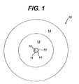
- Figure 1 is a plan view of a surface of a lens of the invention.
- Figure 2 is a depiction of a ray trace model of a progressive lens.
- Figure 3 is a depiction of a ray trace model of a lens of the invention.
- Figure 4 is a depiction of a ray trace model of a progressive lens.
- Figure 5 is a depiction of a ray trace model of a lens of the invention.
-
- The invention provides methods for designing lenses useful for correcting presbyopia, lenses incorporating such designs, and methods for producing these lenses. The lenses are advantageous in that a progressive design is utilized in which ghosting of images is minimized or eliminated. Additionally, the lens' performance on eye is more predictable than other progressive multifocal designs.
- In one embodiment, the invention provides a contact lens comprising, consisting essentially of, and consisting of an optic zone having a progressive power zone comprising, consisting essentially of, and consisting of a distance vision power region, a near vision power region and a transition region therebetween, wherein a substantially opaque annular ring obscures light transmission through the transition region.
- By "progressive power zone" means a continuous, aspheric zone having a distance vision power region and a near vision power region, and a transition region of increasing or decreasing dioptric power connecting the distance and near regions. By "distance vision power region" is meant a region having an amount of refractive power required to correct the lens wearer's distance vision acuity to the desired degree. By "near vision power region" is meant a region having an amount of refractive power required to correct the wearer's near vision acuity to the desired degree.
- In the lenses of the invention, a substantially opaque annular ring overlies the transition region. By "substantially opaque" is meant that the opacity of the annular ring is about 75 to about 100 %, meaning that 75 to 100 % of incident light is absorbed. The amount of opacity used for the ring will depend upon a balancing of the desired visual result from use of the ring with the loss of light that results from increasing opacity. In the lenses of the invention, a range of opacity of about 75 to about 95 % is preferred. The dimension of the ring is such that it substantially corresponds to, or is slightly larger than, the dimensions of the transition region. Typically, the transition region will be about 0.7 to about 1.2 mm in diameter and, thus, the ring will be about 0.7 to about 1.2 mm, preferably 0.95 to about 1.15 mm in diameter. The diameter of the annular ring is such that, in no instance is the ring greater than the lens wearer's pupil regardless of lighting conditions.
- The opacity of the ring may itself be progressive meaning that the opacity increase as one moves from the periphery of the ring towards its innermost edge. The opaque ring may be provided by coating or printing the ring onto a surface of the lens by any convenient method. Suitable tints and pigments useful in coating or printing the ring are well known in the art. Alternatively, the opaque ring may be deposited onto the desired portion of the molding surface of a lens mold. By "molding surface" is meant the surface of a mold or mold half used to form a surface of a lens. Preferably, the deposition is carried out by pad printing by known methods.
- As yet another alternative, the ring may be provided by incorporating a ring-shaped layer of material within the lens material. As still another alternative, the lens surface may be disrupted as, for example, by etching to provide the opaque ring.
- In Figure 1 is depicted a
lens 10 of the invention.Lens 10 has acentral region 11, which is a near vision power region, a transition region (not shown),annular ring 12 overlying the transition region, distancevision power region 13, and non-optical,lenticular region 14.Annular ring 12 has aperiphery 15 and aninnermost edge 16. Operation of the lens is demonstrated as follows. - Figure 2 shows a spot diagram produced using ZEMAX™ raytrace design software. An eye and a lens having progressive power was modeled and a pattern of rays for a 2 mm aperture pupil was traced through them. The lens diameter was 14.4 mm and the entire optic zone diameter was 8 mm. The 2 mm aperture pupil was selected to provide a high luminance, or small pupil, model. The rays are seen as crosses 22 along with
pupil 23 and nearimage 24. The lens is decentered upwardly by approximately 1000 µm and tilted 7 degrees, meaning that the superior portion of the lens tilts toward the eye so that an angle of 7 degrees is formed between that portion of the lens and the original position, or the zero degree position when gazing straight through, of the lens on the eye. In Figure 2, the near image is formed at the top and is surrounded by a number of crosses indicating that there is significant transition and distance region energy close to the near image, which energy will cause the lens wearer to see a ghost image. - In Figure 3 is shown the effect of adding a ring with approximately 100 % opacity, which ring overlies the transition region of the lens of Example 2. The midpoint of the transition region was about 1.0 mm from the center of the lens. The opaque ring begins at a diameter of about 0.9 mm and ends at about 1.12 mm. As shown in Figure 3, no distance and transition region energy is close to the
near image 34 indicating that the lens wearer will not see a ghosted image. - Figure 4 shows a spot diagram for a 3.5 mm aperture pupil. The overall lens diameter was 14.4 mm with an 8 mm diameter optic zone. The lens is decentered upwardly approximately 500 µm and tilted 2.75 degrees toward the eye's surface. In Figure 4, the near image is formed at the top and is surrounded by a number of crosses indicating that there is significant transition and distance region energy close to the near image, which energy will cause the lens wearer to see a ghost image.
- In Figure 5 is shown the effect of adding a ring with a approximately 100 % opacity over the transition region of a lens similar to the lens of Figure 4, except that the aperture is 3.75 mm. The change in aperture was made to determine the effect of the system in conditions of dim light in which the pupil enlarges. The midpoint of the transition region was about 1.0 mm from the lens' center and the opaque ring begins at about 0.9 mm and ends at about 1.12 mm. As shown in Figure 3, no distance and transition region energy is close to the near image 54 indicating that the lens wearer will not see a ghosted image.
- The design of the progressive power zone of the lens of the invention may be provided by utilizing any convenient design. In a preferred design, a speed and a contour for the zone is determined by the following equation:
- Add(x) is actual instantaneous add power at any point x on a surface of the lens;
- x is a point on the lens surface at a distance x from the center;
- a is a constant and preferably is 1;
- Addpeak is the full peak dioptric add power, or add power required for near vision correction;
- xc is the cutoff semi-diameter or the midpoint in the power transition from distance to near power, or near to distance power;
- n is a variable between 1 and 40, preferably between 1 and 20; and
- Add is a value that is equal to the difference in power between the near vision power and distance vision power of the lens.
-
- In Equation I, n is the variable that controls the slope of the progression from near to distance vision power and distance to near vision power in the lens. The less the value of n, the more gradual the progression will be.
- In a second preferred a speed and a contour for the progressive zone is determined by the following equation:
- Add(x) is actual instantaneous add power at any point x on a surface of the lens;
- x is a point on the lens surface at a distance x from the center;
- a is a constant and preferably is 1:
- Addpeak is the full peak dioptric add power;
- xc is the cutoff semi-diameter;
- n is is a variable between 1 and 40, preferably between 1 and 20; and
- Add is a value that is equal to the difference in power between the near vision power and distance vision power of the lens.
-
- In a third embodiment, speed and a contour for the progressive zone is determined by the following equation:
- Add(x) is actual instantaneous add power at any point x on a surface of the lens;
- x is a point on the lens surface at a distance x from the center;
- a is a constant and preferably is 1;
- d is an arbitrary value between 1 and 40;
- Addpeak is the full peak dioptric add power;
- xc is the cutoff semi-diameter;;
- n is between 1 and 40, preferably between 1 and 20; and
- Add is a value that is equal to the difference in power between the near vision power and distance vision power of the lens.
-
- For purposes of this embodiment by "speed" or "contour" is meant the slope of the power change from near to distance power.
- In another embodiment of a design for the progressive zone, a position, an amplitude, and a width for the progressive power zone is determined by the following equation:wherein:

- Y is the Add power at any point x on a surface;
- x is a point on the lens surface;
- a is 0.5;
- k is the point within the power zone at which the power peaks;
- P is the coefficient that controls the width of the power zone and is greater than about 0 and less than about 15;
- S is the coefficient that controls the amplitude and its decrease in the periphery of the zone and is greater than about 0 and less than about 30; and
- Add is a value that is equal to or less than the difference in power between the near vision power and distance vision power of the lens.
-
- By "position" is meant the power zone position in reference to the pupil. By "amplitude" is meant the extent or range of the power progression within the power zone.
- In another method for designing the progressive zone, the rate of change and contour of the power change from distance to near and near to distance vision power is varied. In this embodiment, the progressive zone is such that a rate of change and a contour of a power change between the distance near vision powers is determined according to an equation selected from the group consisting of:
- A is the Add power;
- P is the pupil fraction from 0 to 1; and
- X is greater than 0, preferably greater than 1, and more preferably 2, n, or 2n.
-
- For purposes of Equation V and VI, P is determined as follows. The maximum and minimum pupil diameters are selected along with interval steps from the minimum to the maximum. The interval steps selected are at the designers discretion, but preferably are suitable to facilitate production of the lens as, for example, by computer numerical controlled lathe. From the maximum diameter, the percentage of total diameter P is defined.
- Equation V is used for center distance lens designs meaning that the distance vision power is in the center of the optic zone and the near vision power is at the optic zone's periphery. Equation VI is used for center near lens designs, or lenses in which the near vision power is in the center and the distance vision is at the periphery.
- Alternatively, the progressive zone may be designed so that the rate of change and contour of the power change from distance to near and near to distance vision power is varied using one of the following equations:
- A is the Add power;
- t is the pupil fraction from 90 to 180 degrees; and
- X is greater than 0, preferably greater than 1, and more preferably 2, π, or 2π.
-
- For purposes of Equation VII and VIII, t is determined by selection of the maximum and minimum pupil diameters. The minimum diameter is assigned a value of 90 degrees and the maximum diameter of 180 degrees, in linear intervals.
- Equation VII is used for center distance designs and Equation VIII is used for center near lenses. Thus, as yet another design for the progressive zone a rate of change and a contour of a power change between the distance near vision powers is determined according to and equation selected from the group consisting of:
- A is the Add power;
- t is the pupil fraction from 90 to 180 degrees; and
- X is greater than 0, preferably greater than 1, and more preferably 2, π, or 2π.
-
- The designs of the invention are useful in producing contact lenses that are hard or soft lenses. Soft contact lenses, made of any material suitable for producing such lenses, preferably are used. The lenses of the invention may have any of a variety of corrective optical characteristics incorporated onto the surfaces in addition to distance and near optical powers, such as, for example, cylinder power.
- In the lenses of the invention, the progressive power zone may be on the object-side, or front, surface, the eye-side, or back, surface, or both surfaces. The progressive power zone has at least two regions of differing power, distance and near vision power, and preferably three regions, distance, near, and intermediate vision power. Intermediate power may be supplied as a consequence of the power progression between the peak of the power of the near and distance vision regions. Alternatively, a region of intermediate power may also be designed, as for example by using Equation I.
- The progressive power zone is preferably rotationally symmetric. In the lenses of the invention, the distance, near, and intermediate powers are spherical or toric powers. Additionally, the distance, near, and intermediate optical power regions may be of any desired and practical dimensions.
- The lenses of the invention may be formed by any conventional method. For example, the progressive power zones formed therein may produced by diamond-turning using differing radii. The zones may be diamond-turned into the molds that are used to form the lens of the invention. Subsequently, a suitable liquid resin is placed between the molds followed by compression and curing of the resin to form the lenses of the invention. Alternatively, the zones may be diamond-turned into lens buttons.
Claims (14)
- A contact lens, comprising an optic zone having a progressive power zone comprising a distance vision power region, a near vision power region and a transition region therebetween, wherein a substantially opaque ring obscures light transmission through the transition region.
- The lens of claim 1, wherein the opaque ring comprises an opacity of 75 to 95 percent.
- The lens of claim 1 or claim 2 wherein the opaque ring comprising a diameter of 0.7 to 1.2 mm.
- The lens of any one of claims 1 to 3, wherein the opaque ring increases in opacity from a periphery of the ring to an innermost edge of the ring.
- The lens of any one of claims 1 to 4, wherein the optic zone is located on one of the front or back surfaces of the lens.
- The lens of any one of claims 1 to 5, wherein the progressive power zone further comprises an intermediate vision power region.
- The lens of any one of claims 1 to 6, wherein the distance, near and intermediate power regions comprise spherical powers.
- The lens of any one of claims 1 to 6, wherein the distance, near and intermediate power regions comprise toric powers.
- A method of designing a contact lens comprising the step of:providing an optic zone having a progressive power zone comprising a distance vision power region, a near vision power region and a transition region therebetween; andproviding a substantially opaque ring in the transition region that obscures light transmission through the transition region.
- A method of manufacturing a contact lens comprising the step of:providing an optic zone having a progressive power zone comprising a distance vision power region, a near vision power region and a transition region therebetween; andproviding a substantially opaque ring in the transition region that obscures light transmission through the transition region.
- The method of claim 10, wherein the opaque ring is provided by coating or printing the ring onto a surface of the len.
- The method of claim 10, wherein the opaque ring is provided by depositing the ring onto a desired portion of a molding surface of a lens mold.
- The method of claim 10, wherein the opaque ring is provided by incorporating a ring-shaped layer of material within a lens material.
- The method of claim 10, wherein the opaque ring is provided by etching a surface of a lens.
Applications Claiming Priority (2)
| Application Number | Priority Date | Filing Date | Title |
|---|---|---|---|
| US742123 | 1991-08-08 | ||
| US10/742,123 US7025455B2 (en) | 2003-12-19 | 2003-12-19 | Multifocal contact lenses having a pinhole |
Publications (2)
| Publication Number | Publication Date |
|---|---|
| EP1548489A1 true EP1548489A1 (en) | 2005-06-29 |
| EP1548489B1 EP1548489B1 (en) | 2006-08-16 |
Family
ID=34552815
Family Applications (1)
| Application Number | Title | Priority Date | Filing Date |
|---|---|---|---|
| EP04257891A Expired - Fee Related EP1548489B1 (en) | 2003-12-19 | 2004-12-17 | Progressive power contact lenses having an opaque ring in the transition region |
Country Status (11)
| Country | Link |
|---|---|
| US (1) | US7025455B2 (en) |
| EP (1) | EP1548489B1 (en) |
| JP (1) | JP2005182039A (en) |
| KR (1) | KR20050062426A (en) |
| CN (1) | CN1637466A (en) |
| AU (1) | AU2004237846A1 (en) |
| BR (1) | BRPI0405599A (en) |
| CA (1) | CA2489744A1 (en) |
| DE (1) | DE602004001967T2 (en) |
| HK (1) | HK1077364A1 (en) |
| SG (1) | SG112979A1 (en) |
Cited By (3)
| Publication number | Priority date | Publication date | Assignee | Title |
|---|---|---|---|---|
| US10342656B2 (en) | 2011-12-02 | 2019-07-09 | Acufocus, Inc. | Ocular mask having selective spectral transmission |
| US10449036B2 (en) | 2009-08-13 | 2019-10-22 | Acufocus, Inc. | Masked intraocular implants and lenses |
| EP4066045A4 (en) * | 2019-12-01 | 2024-04-03 | Nthalmic Holding Pty Ltd | Ophthalmic lens designs with non-refractive features |
Families Citing this family (33)
| Publication number | Priority date | Publication date | Assignee | Title |
|---|---|---|---|---|
| WO2000052516A2 (en) | 1999-03-01 | 2000-09-08 | Boston Innovative Optics, Inc. | System and method for increasing the depth of focus of the human eye |
| US7628810B2 (en) | 2003-05-28 | 2009-12-08 | Acufocus, Inc. | Mask configured to maintain nutrient transport without producing visible diffraction patterns |
| US20050046794A1 (en) | 2003-06-17 | 2005-03-03 | Silvestrini Thomas A. | Method and apparatus for aligning a mask with the visual axis of an eye |
| US7976577B2 (en) | 2005-04-14 | 2011-07-12 | Acufocus, Inc. | Corneal optic formed of degradation resistant polymer |
| US9943401B2 (en) * | 2008-04-04 | 2018-04-17 | Eugene de Juan, Jr. | Therapeutic device for pain management and vision |
| US20100073631A1 (en) * | 2008-09-22 | 2010-03-25 | Dretzke Debra A | Device and method for reducing visual aberration |
| US10004593B2 (en) | 2009-08-13 | 2018-06-26 | Acufocus, Inc. | Intraocular lens with elastic mask |
| BR112012008079A2 (en) | 2009-08-13 | 2016-03-01 | Acufocus Inc | corneal graft with nutrient transport structures |
| US8591025B1 (en) | 2012-09-11 | 2013-11-26 | Nexisvision, Inc. | Eye covering and refractive correction methods for LASIK and other applications |
| US9498385B2 (en) | 2009-10-23 | 2016-11-22 | Nexisvision, Inc. | Conformable therapeutic shield for vision and pain |
| ES2649890T3 (en) | 2009-10-23 | 2018-01-16 | Nexisvision, Inc. | Corneal enervation for the treatment of eye pain |
| USD656526S1 (en) | 2009-11-10 | 2012-03-27 | Acufocus, Inc. | Ocular mask |
| JP2013544132A (en) | 2010-10-25 | 2013-12-12 | ネクシスビジョン, インコーポレイテッド | Method and apparatus for identifying eye coverings for vision |
| US8678584B2 (en) | 2012-04-20 | 2014-03-25 | Nexisvision, Inc. | Contact lenses for refractive correction |
| CA2834295A1 (en) | 2011-04-28 | 2012-11-01 | Nexisvision, Inc. | Eye covering and refractive correction methods and apparatus having improved tear flow, comfort, and/or applicability |
| TWI588560B (en) | 2012-04-05 | 2017-06-21 | 布萊恩荷登視覺協會 | Lenses, devices, methods and systems for refractive error |
| US9465233B2 (en) | 2012-04-20 | 2016-10-11 | Nexisvision, Inc. | Bimodular contact lenses |
| JP6298810B2 (en) | 2012-04-20 | 2018-03-20 | ネクシスビジョン リクイデーション トラスト | Contact lenses for refractive correction |
| US9201250B2 (en) | 2012-10-17 | 2015-12-01 | Brien Holden Vision Institute | Lenses, devices, methods and systems for refractive error |
| EP2908773B1 (en) | 2012-10-17 | 2024-01-03 | Brien Holden Vision Institute | Lenses, devices, methods and systems for refractive error |
| US9204962B2 (en) | 2013-03-13 | 2015-12-08 | Acufocus, Inc. | In situ adjustable optical mask |
| US9427922B2 (en) | 2013-03-14 | 2016-08-30 | Acufocus, Inc. | Process for manufacturing an intraocular lens with an embedded mask |
| JP6310072B2 (en) | 2013-06-26 | 2018-04-11 | ネクシスビジョン, インコーポレイテッド | Contact lenses for refractive correction |
| US9341864B2 (en) | 2013-11-15 | 2016-05-17 | Nexisvision, Inc. | Contact lenses having a reinforcing scaffold |
| WO2015116559A1 (en) | 2014-01-29 | 2015-08-06 | Nexisvision, Inc. | Multifocal bimodulus contact lenses |
| US9594259B2 (en) * | 2014-08-29 | 2017-03-14 | Johnson & Johnson Vision Care, Inc. | Mask lens design and method for preventing and/or slowing myopia progression |
| ES2529267B1 (en) | 2014-09-25 | 2015-12-18 | Sergio Oscar Luque | Multifocal intraocular lens with extended depth of field |
| WO2016081493A1 (en) | 2014-11-19 | 2016-05-26 | Acufocus, Inc. | Fracturable mask for treating presbyopia |
| USD844145S1 (en) * | 2014-12-22 | 2019-03-26 | Henry Ford Health System | Vision assessment chart |
| WO2017062316A1 (en) | 2015-10-05 | 2017-04-13 | Acufocus, Inc. | Methods of molding intraocular lenses |
| EP3384342B1 (en) | 2015-11-24 | 2021-08-25 | AcuFocus, Inc. | Toric small aperture intraocular lens with extended depth of focus |
| US11364110B2 (en) | 2018-05-09 | 2022-06-21 | Acufocus, Inc. | Intraocular implant with removable optic |
| USD948724S1 (en) | 2019-04-16 | 2022-04-12 | Henry Ford Health System | Vision assessment chart |
Citations (2)
| Publication number | Priority date | Publication date | Assignee | Title |
|---|---|---|---|---|
| US5662706A (en) * | 1996-06-14 | 1997-09-02 | Pbh, Inc. | Variable transmissivity annular mask lens for the treatment of optical aberrations |
| US6544286B1 (en) * | 2000-07-18 | 2003-04-08 | Tissue Engineering Refraction, Inc. | Pre-fabricated corneal tissue lens method of corneal overlay to correct vision |
Family Cites Families (15)
| Publication number | Priority date | Publication date | Assignee | Title |
|---|---|---|---|---|
| ES381509A2 (en) | 1970-01-05 | 1973-05-01 | Plastic Contact Lens Company | Contact lenses |
| US3794414A (en) | 1972-05-12 | 1974-02-26 | Jessen Inc Wesley | Multiple focal contact lens |
| US4976732A (en) | 1984-09-12 | 1990-12-11 | International Financial Associates Holdings, Inc. | Optical lens for the human eye |
| US4744647A (en) | 1984-12-04 | 1988-05-17 | Lens Plus Co. | Semi-opaque corneal contact lens or intraoccular lens and method of formation |
| US4955904A (en) | 1989-08-21 | 1990-09-11 | The Beth Israel Hospital Association | Masked intraocular lens and method for treating a patient with cataracts |
| US5260727A (en) | 1990-10-22 | 1993-11-09 | Oksman Henry C | Wide depth of focus intraocular and contact lenses |
| US5786883A (en) | 1991-11-12 | 1998-07-28 | Pilkington Barnes Hind, Inc. | Annular mask contact lenses |
| US5245367A (en) | 1991-11-12 | 1993-09-14 | David Miller | Annular mask contact lenses |
| US5434630A (en) | 1993-09-27 | 1995-07-18 | Bransome; Robert | Corrective contact lens system |
| US5608741A (en) * | 1993-11-23 | 1997-03-04 | Intel Corporation | Fast parity generator using complement pass-transistor logic |
| IL117937A0 (en) * | 1995-05-04 | 1996-08-04 | Johnson & Johnson Vision Prod | Combined multifocal toric lens designs |
| US5608471A (en) | 1995-07-03 | 1997-03-04 | Westcon Contact Lens Co., Inc. | Soft, bifocal contact lens |
| US5905561A (en) | 1996-06-14 | 1999-05-18 | Pbh, Inc. | Annular mask lens having diffraction reducing edges |
| US5980040A (en) | 1997-06-30 | 1999-11-09 | Wesley Jessen Corporation | Pinhole lens and contact lens |
| WO2000052516A2 (en) | 1999-03-01 | 2000-09-08 | Boston Innovative Optics, Inc. | System and method for increasing the depth of focus of the human eye |
-
2003
- 2003-12-19 US US10/742,123 patent/US7025455B2/en not_active Expired - Lifetime
-
2004
- 2004-12-10 AU AU2004237846A patent/AU2004237846A1/en not_active Abandoned
- 2004-12-10 CA CA002489744A patent/CA2489744A1/en not_active Abandoned
- 2004-12-16 BR BR0405599-3A patent/BRPI0405599A/en not_active Application Discontinuation
- 2004-12-16 SG SG200407457A patent/SG112979A1/en unknown
- 2004-12-17 CN CNA2004100104613A patent/CN1637466A/en active Pending
- 2004-12-17 DE DE602004001967T patent/DE602004001967T2/en not_active Expired - Fee Related
- 2004-12-17 JP JP2004366461A patent/JP2005182039A/en active Pending
- 2004-12-17 KR KR1020040107734A patent/KR20050062426A/en not_active Application Discontinuation
- 2004-12-17 EP EP04257891A patent/EP1548489B1/en not_active Expired - Fee Related
-
2005
- 2005-10-20 HK HK05109248A patent/HK1077364A1/en not_active IP Right Cessation
Patent Citations (2)
| Publication number | Priority date | Publication date | Assignee | Title |
|---|---|---|---|---|
| US5662706A (en) * | 1996-06-14 | 1997-09-02 | Pbh, Inc. | Variable transmissivity annular mask lens for the treatment of optical aberrations |
| US6544286B1 (en) * | 2000-07-18 | 2003-04-08 | Tissue Engineering Refraction, Inc. | Pre-fabricated corneal tissue lens method of corneal overlay to correct vision |
Cited By (3)
| Publication number | Priority date | Publication date | Assignee | Title |
|---|---|---|---|---|
| US10449036B2 (en) | 2009-08-13 | 2019-10-22 | Acufocus, Inc. | Masked intraocular implants and lenses |
| US10342656B2 (en) | 2011-12-02 | 2019-07-09 | Acufocus, Inc. | Ocular mask having selective spectral transmission |
| EP4066045A4 (en) * | 2019-12-01 | 2024-04-03 | Nthalmic Holding Pty Ltd | Ophthalmic lens designs with non-refractive features |
Also Published As
| Publication number | Publication date |
|---|---|
| DE602004001967T2 (en) | 2007-02-15 |
| HK1077364A1 (en) | 2006-02-10 |
| SG112979A1 (en) | 2005-07-28 |
| CN1637466A (en) | 2005-07-13 |
| DE602004001967D1 (en) | 2006-09-28 |
| AU2004237846A1 (en) | 2005-07-07 |
| US7025455B2 (en) | 2006-04-11 |
| CA2489744A1 (en) | 2005-06-19 |
| BRPI0405599A (en) | 2005-08-30 |
| JP2005182039A (en) | 2005-07-07 |
| KR20050062426A (en) | 2005-06-23 |
| EP1548489B1 (en) | 2006-08-16 |
| US20050134793A1 (en) | 2005-06-23 |
Similar Documents
| Publication | Publication Date | Title |
|---|---|---|
| US7025455B2 (en) | Multifocal contact lenses having a pinhole | |
| CA2456539C (en) | Methods for designing multifocal ophthalmic lenses | |
| CN101981489B (en) | Lenses for the correction of presbyopia and methods of designing the lenses | |
| CA2536147C (en) | Rotationally stabilized contact lenses | |
| JP4294865B2 (en) | Progressive multifocal contact lens suitable for presbyopia compensation | |
| AU2002324554A1 (en) | Methods for designing multifocal ophthalmic lenses | |
| US20220011602A1 (en) | Light scattering lens for treating myopia and eyeglasses containing the same | |
| EP1805550A1 (en) | Multifocal lenses for pre-presbyopic individuals | |
| WO1997019383A1 (en) | Multifocal lens for eyeglasses and eyeglass lens | |
| JP2000105358A (en) | Gradually additional type lens | |
| US6874887B2 (en) | Multifocal contact lens | |
| EP1468324B1 (en) | Multifocal ophthalmic lenses | |
| JPH0520729B2 (en) | ||
| JPH05181096A (en) | Multifocal eye lens and its production | |
| CN105572901B (en) | Aspheric diffractive contact lens for correcting myopia and presbyopia | |
| KR101359721B1 (en) | Improved Single Vision Spectacle Lens | |
| JP3013396B2 (en) | Eyeglass lens | |
| WO2023072930A1 (en) | Lens element | |
| CA2587796A1 (en) | Multifocal ophthalmic lenses |
Legal Events
| Date | Code | Title | Description |
|---|---|---|---|
| PUAI | Public reference made under article 153(3) epc to a published international application that has entered the european phase |
Free format text: ORIGINAL CODE: 0009012 |
|
| AK | Designated contracting states |
Kind code of ref document: A1 Designated state(s): AT BE BG CH CY CZ DE DK EE ES FI FR GB GR HU IE IS IT LI LT LU MC NL PL PT RO SE SI SK TR |
|
| AX | Request for extension of the european patent |
Extension state: AL BA HR LV MK YU |
|
| 17P | Request for examination filed |
Effective date: 20051214 |
|
| REG | Reference to a national code |
Ref country code: HK Ref legal event code: DE Ref document number: 1077364 Country of ref document: HK |
|
| GRAP | Despatch of communication of intention to grant a patent |
Free format text: ORIGINAL CODE: EPIDOSNIGR1 |
|
| AKX | Designation fees paid |
Designated state(s): DE FR GB IE IT |
|
| GRAS | Grant fee paid |
Free format text: ORIGINAL CODE: EPIDOSNIGR3 |
|
| GRAA | (expected) grant |
Free format text: ORIGINAL CODE: 0009210 |
|
| AK | Designated contracting states |
Kind code of ref document: B1 Designated state(s): DE FR GB IE IT |
|
| REG | Reference to a national code |
Ref country code: GB Ref legal event code: FG4D |
|
| REG | Reference to a national code |
Ref country code: IE Ref legal event code: FG4D |
|
| REF | Corresponds to: |
Ref document number: 602004001967 Country of ref document: DE Date of ref document: 20060928 Kind code of ref document: P |
|
| PGFP | Annual fee paid to national office [announced via postgrant information from national office to epo] |
Ref country code: FR Payment date: 20061208 Year of fee payment: 3 |
|
| PGFP | Annual fee paid to national office [announced via postgrant information from national office to epo] |
Ref country code: IE Payment date: 20061213 Year of fee payment: 3 |
|
| PGFP | Annual fee paid to national office [announced via postgrant information from national office to epo] |
Ref country code: DE Payment date: 20061214 Year of fee payment: 3 |
|
| REG | Reference to a national code |
Ref country code: HK Ref legal event code: GR Ref document number: 1077364 Country of ref document: HK |
|
| ET | Fr: translation filed | ||
| PLBE | No opposition filed within time limit |
Free format text: ORIGINAL CODE: 0009261 |
|
| STAA | Information on the status of an ep patent application or granted ep patent |
Free format text: STATUS: NO OPPOSITION FILED WITHIN TIME LIMIT |
|
| 26N | No opposition filed |
Effective date: 20070518 |
|
| PG25 | Lapsed in a contracting state [announced via postgrant information from national office to epo] |
Ref country code: IE Free format text: LAPSE BECAUSE OF NON-PAYMENT OF DUE FEES Effective date: 20071217 Ref country code: DE Free format text: LAPSE BECAUSE OF NON-PAYMENT OF DUE FEES Effective date: 20080701 |
|
| REG | Reference to a national code |
Ref country code: FR Ref legal event code: ST Effective date: 20081020 |
|
| PG25 | Lapsed in a contracting state [announced via postgrant information from national office to epo] |
Ref country code: FR Free format text: LAPSE BECAUSE OF NON-PAYMENT OF DUE FEES Effective date: 20071231 |
|
| GBPC | Gb: european patent ceased through non-payment of renewal fee |
Effective date: 20081217 |
|
| PGFP | Annual fee paid to national office [announced via postgrant information from national office to epo] |
Ref country code: IT Payment date: 20071231 Year of fee payment: 4 |
|
| PG25 | Lapsed in a contracting state [announced via postgrant information from national office to epo] |
Ref country code: GB Free format text: LAPSE BECAUSE OF NON-PAYMENT OF DUE FEES Effective date: 20081217 |
|
| PG25 | Lapsed in a contracting state [announced via postgrant information from national office to epo] |
Ref country code: IT Free format text: LAPSE BECAUSE OF NON-PAYMENT OF DUE FEES Effective date: 20081217 |