EP1548293A2 - An integrated unit for air treatment in pneumatic systems - Google Patents
An integrated unit for air treatment in pneumatic systems Download PDFInfo
- Publication number
- EP1548293A2 EP1548293A2 EP04029428A EP04029428A EP1548293A2 EP 1548293 A2 EP1548293 A2 EP 1548293A2 EP 04029428 A EP04029428 A EP 04029428A EP 04029428 A EP04029428 A EP 04029428A EP 1548293 A2 EP1548293 A2 EP 1548293A2
- Authority
- EP
- European Patent Office
- Prior art keywords
- unit
- outlet
- inlet
- pressure
- valve
- Prior art date
- Legal status (The legal status is an assumption and is not a legal conclusion. Google has not performed a legal analysis and makes no representation as to the accuracy of the status listed.)
- Granted
Links
Images


Classifications
-
- F—MECHANICAL ENGINEERING; LIGHTING; HEATING; WEAPONS; BLASTING
- F15—FLUID-PRESSURE ACTUATORS; HYDRAULICS OR PNEUMATICS IN GENERAL
- F15B—SYSTEMS ACTING BY MEANS OF FLUIDS IN GENERAL; FLUID-PRESSURE ACTUATORS, e.g. SERVOMOTORS; DETAILS OF FLUID-PRESSURE SYSTEMS, NOT OTHERWISE PROVIDED FOR
- F15B21/00—Common features of fluid actuator systems; Fluid-pressure actuator systems or details thereof, not covered by any other group of this subclass
- F15B21/04—Special measures taken in connection with the properties of the fluid
- F15B21/048—Arrangements for compressed air preparation, e.g. comprising air driers, air condensers, filters, lubricators or pressure regulators
-
- F—MECHANICAL ENGINEERING; LIGHTING; HEATING; WEAPONS; BLASTING
- F15—FLUID-PRESSURE ACTUATORS; HYDRAULICS OR PNEUMATICS IN GENERAL
- F15B—SYSTEMS ACTING BY MEANS OF FLUIDS IN GENERAL; FLUID-PRESSURE ACTUATORS, e.g. SERVOMOTORS; DETAILS OF FLUID-PRESSURE SYSTEMS, NOT OTHERWISE PROVIDED FOR
- F15B11/00—Servomotor systems without provision for follow-up action; Circuits therefor
- F15B11/06—Servomotor systems without provision for follow-up action; Circuits therefor involving features specific to the use of a compressible medium, e.g. air, steam
- F15B11/068—Servomotor systems without provision for follow-up action; Circuits therefor involving features specific to the use of a compressible medium, e.g. air, steam with valves for gradually putting pneumatic systems under pressure
-
- F—MECHANICAL ENGINEERING; LIGHTING; HEATING; WEAPONS; BLASTING
- F15—FLUID-PRESSURE ACTUATORS; HYDRAULICS OR PNEUMATICS IN GENERAL
- F15B—SYSTEMS ACTING BY MEANS OF FLUIDS IN GENERAL; FLUID-PRESSURE ACTUATORS, e.g. SERVOMOTORS; DETAILS OF FLUID-PRESSURE SYSTEMS, NOT OTHERWISE PROVIDED FOR
- F15B21/00—Common features of fluid actuator systems; Fluid-pressure actuator systems or details thereof, not covered by any other group of this subclass
- F15B21/04—Special measures taken in connection with the properties of the fluid
- F15B21/041—Removal or measurement of solid or liquid contamination, e.g. filtering
-
- F—MECHANICAL ENGINEERING; LIGHTING; HEATING; WEAPONS; BLASTING
- F15—FLUID-PRESSURE ACTUATORS; HYDRAULICS OR PNEUMATICS IN GENERAL
- F15B—SYSTEMS ACTING BY MEANS OF FLUIDS IN GENERAL; FLUID-PRESSURE ACTUATORS, e.g. SERVOMOTORS; DETAILS OF FLUID-PRESSURE SYSTEMS, NOT OTHERWISE PROVIDED FOR
- F15B2211/00—Circuits for servomotor systems
- F15B2211/50—Pressure control
- F15B2211/505—Pressure control characterised by the type of pressure control means
- F15B2211/50554—Pressure control characterised by the type of pressure control means the pressure control means controlling a pressure downstream of the pressure control means, e.g. pressure reducing valve
-
- F—MECHANICAL ENGINEERING; LIGHTING; HEATING; WEAPONS; BLASTING
- F15—FLUID-PRESSURE ACTUATORS; HYDRAULICS OR PNEUMATICS IN GENERAL
- F15B—SYSTEMS ACTING BY MEANS OF FLUIDS IN GENERAL; FLUID-PRESSURE ACTUATORS, e.g. SERVOMOTORS; DETAILS OF FLUID-PRESSURE SYSTEMS, NOT OTHERWISE PROVIDED FOR
- F15B2211/00—Circuits for servomotor systems
- F15B2211/50—Pressure control
- F15B2211/515—Pressure control characterised by the connections of the pressure control means in the circuit
- F15B2211/5158—Pressure control characterised by the connections of the pressure control means in the circuit being connected to a pressure source and an output member
-
- F—MECHANICAL ENGINEERING; LIGHTING; HEATING; WEAPONS; BLASTING
- F15—FLUID-PRESSURE ACTUATORS; HYDRAULICS OR PNEUMATICS IN GENERAL
- F15B—SYSTEMS ACTING BY MEANS OF FLUIDS IN GENERAL; FLUID-PRESSURE ACTUATORS, e.g. SERVOMOTORS; DETAILS OF FLUID-PRESSURE SYSTEMS, NOT OTHERWISE PROVIDED FOR
- F15B2211/00—Circuits for servomotor systems
- F15B2211/60—Circuit components or control therefor
- F15B2211/61—Secondary circuits
- F15B2211/611—Diverting circuits, e.g. for cooling or filtering
-
- F—MECHANICAL ENGINEERING; LIGHTING; HEATING; WEAPONS; BLASTING
- F15—FLUID-PRESSURE ACTUATORS; HYDRAULICS OR PNEUMATICS IN GENERAL
- F15B—SYSTEMS ACTING BY MEANS OF FLUIDS IN GENERAL; FLUID-PRESSURE ACTUATORS, e.g. SERVOMOTORS; DETAILS OF FLUID-PRESSURE SYSTEMS, NOT OTHERWISE PROVIDED FOR
- F15B2211/00—Circuits for servomotor systems
- F15B2211/60—Circuit components or control therefor
- F15B2211/615—Filtering means
-
- F—MECHANICAL ENGINEERING; LIGHTING; HEATING; WEAPONS; BLASTING
- F15—FLUID-PRESSURE ACTUATORS; HYDRAULICS OR PNEUMATICS IN GENERAL
- F15B—SYSTEMS ACTING BY MEANS OF FLUIDS IN GENERAL; FLUID-PRESSURE ACTUATORS, e.g. SERVOMOTORS; DETAILS OF FLUID-PRESSURE SYSTEMS, NOT OTHERWISE PROVIDED FOR
- F15B2211/00—Circuits for servomotor systems
- F15B2211/60—Circuit components or control therefor
- F15B2211/635—Circuits providing pilot pressure to pilot pressure-controlled fluid circuit elements
- F15B2211/6355—Circuits providing pilot pressure to pilot pressure-controlled fluid circuit elements having valve means
-
- Y—GENERAL TAGGING OF NEW TECHNOLOGICAL DEVELOPMENTS; GENERAL TAGGING OF CROSS-SECTIONAL TECHNOLOGIES SPANNING OVER SEVERAL SECTIONS OF THE IPC; TECHNICAL SUBJECTS COVERED BY FORMER USPC CROSS-REFERENCE ART COLLECTIONS [XRACs] AND DIGESTS
- Y10—TECHNICAL SUBJECTS COVERED BY FORMER USPC
- Y10S—TECHNICAL SUBJECTS COVERED BY FORMER USPC CROSS-REFERENCE ART COLLECTIONS [XRACs] AND DIGESTS
- Y10S55/00—Gas separation
- Y10S55/17—Compressed air water removal
-
- Y—GENERAL TAGGING OF NEW TECHNOLOGICAL DEVELOPMENTS; GENERAL TAGGING OF CROSS-SECTIONAL TECHNOLOGIES SPANNING OVER SEVERAL SECTIONS OF THE IPC; TECHNICAL SUBJECTS COVERED BY FORMER USPC CROSS-REFERENCE ART COLLECTIONS [XRACs] AND DIGESTS
- Y10—TECHNICAL SUBJECTS COVERED BY FORMER USPC
- Y10T—TECHNICAL SUBJECTS COVERED BY FORMER US CLASSIFICATION
- Y10T137/00—Fluid handling
- Y10T137/2496—Self-proportioning or correlating systems
- Y10T137/2559—Self-controlled branched flow systems
- Y10T137/2562—Dividing and recombining
-
- Y—GENERAL TAGGING OF NEW TECHNOLOGICAL DEVELOPMENTS; GENERAL TAGGING OF CROSS-SECTIONAL TECHNOLOGIES SPANNING OVER SEVERAL SECTIONS OF THE IPC; TECHNICAL SUBJECTS COVERED BY FORMER USPC CROSS-REFERENCE ART COLLECTIONS [XRACs] AND DIGESTS
- Y10—TECHNICAL SUBJECTS COVERED BY FORMER USPC
- Y10T—TECHNICAL SUBJECTS COVERED BY FORMER US CLASSIFICATION
- Y10T137/00—Fluid handling
- Y10T137/8593—Systems
- Y10T137/877—With flow control means for branched passages
- Y10T137/87885—Sectional block structure
Definitions
- the present invention relates to an integrated unit performing a plurality of functions related to air treatment in pneumatic systems.
- All known units consist of individual elements, each having a specific function, that are then assembled in series with each other.
- the most traditional combination of elements used in automation may comprise a manual on-off valve at the inlet, a filter, a pressure regulator, an electric on-off valve, a pressure switch, several intakes, etc.
- the elements can be someway of the modular type so as to have attachments and sizes compatible with each other in the same series, but in any case they are always elements that must be assembled one after the other.
- the servicing interventions such as replacement of the filter cartridge
- the servicing interventions are difficult and often uncomfortable, above all when the unit is positioned in regions of the machine utilizing it that are hardly accessible.
- the cartridge in order to receive the condensate at the filter base, the cartridge is always disposed vertically in a cup under the air inlet, with the air flow that is radially directed from the cartridge outside to the inside.
- Such an arrangement creates problems in terms of vertical bulkiness that can be hardly resolved, so that uncomfortable operations are required even if the filter cup is only to be unscrewed.
- a still further aim of the present invention is to provide the unit with a regulation device for progressive starting that is of reduced bulkiness and is capable of offering a satisfactory progressive starting irrespective of the conditions of the circuit downstream thereof.
- an integrated unit for air treatment in pneumatic systems which comprises a box-shaped body provided with an inlet for the air to be treated and with at least one outlet for the treated air and containing devices for treatment and regulation of the air flow between the inlet and outlet, said devices comprising at least one filter device, one pressure regulator and one progressive-starting device.
- Unit 210 has a generally parallelepiped or box-shaped conformation with a body 10 on the external surface of which connectors, commands, indicators, etc. appear.
- a main inlet connector 11 and an opposite main outlet connector 12 are present.
- an auxiliary outlet 13 which is filtered but not regulated and two auxiliary outlets 14, 15 in parallel to the main outlet 12 but with a connector of different diameter (1/4", for example) can be present. All connectors are disposed on side faces.
- the indicators and commands are disposed on the front panel. As clarified in the following, they comprise, among other things, a regulator 224 for regulation of the progressive-starting function and a manual shutoff and air-discharge valve 228.
- a regulator 224 for regulation of the progressive-starting function
- a manual shutoff and air-discharge valve 228 may be also the presence of a pilot pressure regulator 227, an outlet pressure switch 17, a manometer 16 and LED signallers visually indicating the activation state of the pressure switch and the state of a possible inner solenoid valve (denoted at 229 in Fig. 4).
- the connections of the manometer and pressure switch at the exit of the device are well visible in the section in Fig. 5 as well.
- unit 210 also comprises a filter device 114 whose plug 120 for access to the cartridge is disposed with a horizontal axis and appears on the front panel as well, and a condensate discharging device 115 with a lower outlet 127 for the water and projecting from the lower side of the unit.
- an electric side connector 18 reproducing the electric signals of the pressure switch and LED indicators and said connector 18 is powered and receives the activation signal from the solenoid valve.
- Fig. 2 Shown in Fig. 2 is part of the whole unit. In particular, clearly shown is the main inlet connector 11, the device portion 110 concerning filtering and condensate discharge, with the filter unit 114 and the condensate collection and discharge assembly 115, a piloted valve 212 for pressure regulation, a piloting unit with progressive starting 215.
- Fig. 3 Diagrammatically shown in Fig. 3 is a section taken along line III-III in Fig. 2 of the portion 110 of unit 210 carrying out air filtering and condensate discharge, in accordance with a preferred solution of the invention.
- the filter and condensate discharge region comprises a body 111 (advantageously of one piece with the body of the remainder of the unit) provided with an inlet 112 for the air to be filtered coming from the main inlet connector 11, and an outlet 113 for the filtered air which is directed to the remainder of the unit and towards the main outlet connector 12.
- body 111 Housed in body 111 is the filter unit 114 and the condensate collection and discharge assembly 115.
- the filter unit 114 is advantageously extended along a horizontal axis 116 while the condensate assembly 115 is disposed under the filter unit and is extended along a vertical axis 117.
- the condensate assembly is disposed downstream of the filter unit and the air flow radially passes through the filter from the inside to the outside.
- the filter unit is provided with a suitable cylindrical filtering cartridge 118, received in a suitable seat 119 sealingly closed by the threaded plug 120, also of horizontal axis 116.
- the air inlet 112 communicates with the inside of cartridge 118 through an on-off valve 121 the closure member 122 of which is pushed and closed against an abutment 123 by the action of a spring 124.
- Axially present internally of the plug 120 is a rod 125 that, when the plug 120 is correctly screwed down in place, keeps the valve open against the action of spring 124.
- the condensate assembly 115 comprises a cup 126 for collection of the condensate entrained through the filter.
- the cup has a lower exhaust outlet 127 that can be operated either manually (with a screw threaded plug or a valve, for example) or advantageously in an automatic manner by a known float valve 128 opening when the liquid level in the cup exceeds a predetermined threshold.
- the cup 126 top is a system consisting of inclined lamellae 129 such disposed that they are licked by the air flow directed towards the outlet 113 so as to separate the condensate from the flow itself and cause dripping of the condensate into the underlying cup.
- the horizontal arrangement of the filter with front extraction makes the device both compact and of easy placement and quick maintenance.
- the air flow passing through the filter cartridge from the inside to the outside causes the intercepted dirt to remain internally of the cartridge when the latter is removed from its seat, which will facilitate replacement of the cartridge and make it quicker.
- Separation of the condensate after filtering also prevents particles of dirt from reaching the condensate assembly and stopping or clogging the exhaust outlet. This ensures a high reliability of the possible advantageous self-discharge device.
- the outlet 113 after discharge of the condensate directly leads to a regulation valve 212 provided with a closure member 240 that, urged by a spring 241, closes passage to the outlet 12.
- the closure member 240 is operated for opening by a control piston 242 which is acted upon, on the side towards the closure member, by the outlet pressure (through a passage 243) and, on the side opposite to the closure member, by a control pressure (through a passage 213).
- a pressure regulating valve 212 of the differential type is obtained, i.e. a regulation member that is movable by means of the opposite thrusts produced by the pressure coming out of the regulator itself and by the pressure at the piloting inlet 213.
- the piloting inlet is controlled by a piloting module or unit, generally denoted at 215, to perform, among other things, the function of progressive starting.
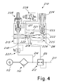
- piloting unit 215 is shown in Fig. 4 (in an extended view for better understanding).
- This unit 215 comprises an inlet 230 that will be connected upstream of valve 212 (through a passage 214, not shown in Fig. 2), and an outlet 211 directed to the outlet connector 12.
- regulator 212 Connected upstream of regulator 212 is the inlet of a secondary circuit 214 leading to a piloting unit 215 supplying the piloting command 213 to valve 212.
- the piloting unit comprises a progressive starting device 216 fed from the inlet 214 and sending air from the outlet 226 to the piloting command 213.
- device 216 comprises an inlet duct 217 connected to the inlet 214, possibly through further control members to be described in the following.
- Duct 217 is divided into a main branch 218, connected with the outlet 226 through an on-off valve or closure member 219 pushed for closure by a spring 220, and a secondary branch 221 reaching the outlet 226 through a throttled passage 222.
- Throttling 222 can be advantageously obtained in an adjustable manner by means of a pin 223 axially movable through an adjusting hand grip 224.
- a distributor or slide valve 225 exerts pressure on the closure member 219 in the direction of the opening thereof, against the action of spring 220, due to the pressure to which it is subjected that is created in the outlet duct 226.
- the flow rate established by the pin produces a gradual pressure increase in the outlet duct until the thrust present on the side downstream of the closure member 219 overcomes the thrust on the upstream side and the closure member opens the main duct 218 to the outlet.
- pressure variation on the outlet 226 is used to consequently control operation of valve 212 that will thus produce a corresponding pressure variation in the outlet line 211. Obviously the variation on the outlet 211 takes place irrespective of what is connected therewith.
- the true progressive starter acts on piloting of a valve instead of being directly placed on the main line, which on the contrary happens in the known art.
- the progressive starter 216 must be sized for the (very reduced) pilot flow rate necessary for regulator 212 and not for the much bigger flow rate of the main line 211. This enables a progressive starting unit to be made which is of much more reduced bulkiness than in the solutions of the known art. The intrinsic sturdiness of the unit is also favored.
- the piloting circuit of valve 212 with which the progressive starter is connected can also advantageously be a pilot circuit for pressure regulation on the main line.
- a known pilot pressure regulator 227 is placed, pressure stabilization on the outlet line 211 occurs during normal operation after the progressive starting.
- also provided in series with the pilot regulator can be a manual valve 228 and/or an electric valve 229, of the type 3/2.
- valve 228 can be inserted in the body of the progressive starter. Valves 228, 229 enable opening and closure of valve 212 to be carried out in a controlled manner.
- the whole unit is substantially formed of two bodies, the main one 20, with the filter, the controlled valve 212 and all the ducts between the inlet and outlets, and a secondary body implementing the control module 215. Due to the front arrangement of the displays and commands, the device can be easily mounted on a panel.
Landscapes
- Engineering & Computer Science (AREA)
- Fluid Mechanics (AREA)
- Mechanical Engineering (AREA)
- General Engineering & Computer Science (AREA)
- Physics & Mathematics (AREA)
- Chemical & Material Sciences (AREA)
- Analytical Chemistry (AREA)
- Exposure Of Semiconductors, Excluding Electron Or Ion Beam Exposure (AREA)
- Control Of Fluid Pressure (AREA)
- Filtering Of Dispersed Particles In Gases (AREA)
- Jigs For Machine Tools (AREA)
- Exhaust Gas Treatment By Means Of Catalyst (AREA)
- Respiratory Apparatuses And Protective Means (AREA)
- Fluid-Pressure Circuits (AREA)
- Chemical Treatment Of Metals (AREA)
- Sampling And Sample Adjustment (AREA)
- Separation By Low-Temperature Treatments (AREA)
Abstract
Description
- Fig. 1 is a diagrammatic front view of a unit in accordance with the invention;
- Fig. 2 is a diagrammatic view partly in section of part of the inside of the unit seen in Fig. 1;
- Fig. 3 is a diagrammatic view of the unit taken along line III-III in Fig. 2;
- Fig. 4 is a diagrammatic view in section of a detail of the unit where also part of the block diagram of the unit circuit is represented;
- Fig. 5 is a diagrammatic view of the unit taken along line V-V in Fig. 2.
Claims (23)
- An integrated unit for air treatment in pneumatic systems comprising a box-shaped body provided with an inlet for the air to be treated and at least one outlet for the treated air and holding devices for air flow treatment and regulation between the inlet and outlet, said devices comprising at least one filter device (114), a pressure-regulating valve (212) and a progressive starting device (212, 215).
- A unit as claimed in claim 1, characterized in that it is provided with commands for the treatment and regulation devices, which commands are disposed on the front face of the box-shaped body, and in that the connectors for said inlet and the at least one outlet are disposed on side faces of the box-shaped body.
- A unit as claimed in claim 1, characterized in that appearing on the front face of the box-shaped body is a pressure switch (17) and a manometer (16) that are connected to said outlet (12).
- A unit as claimed in claim 1, characterized in that comprised in said box-shaped body is a main body (20) holding at least the ducts between the inlet and outlet, the filter device and said pressure-regulating valve (212), and an auxiliary body that in turn holds a pilot device (215) of the pressure-regulating valve to implement said progressive starting device that is assembled with the main body.
- A unit as claimed in claim 1, characterized in that the pressure-regulating valve (212) is disposed downstream of the filter device and comprises a closure member (240) which, urged by a spring (241), closes the passage towards the outlet (12), the closure member (240) being driven to the open position by a control piston (242) which is acted upon, on the side towards the closure member, by the pressure on the outlet (12) and, on the side opposite to the closure member, by a control pressure reaching said pilot device (215).
- A unit as claimed in claim 1, characterized in that the filter device comprises a filter cartridge (118) extended along a horizontal axis, and is provided with a plug (120) that can be opened for removal of the cartridge (118), said plug appearing on a front face of the box-shaped body.
- A unit as claimed in claim 1, characterized in that said treatment and regulation devices further comprise a device (115) for collection and discharge of the condensate, which device appears on a lower side face of the box-shaped body.
- A unit as claimed in claim 7, characterized in that the condensate collection and discharge device (115) is disposed under and downstream of the filter device.
- A unit as claimed in claim 6, characterized in that the air inlet (11) communicates with the inside of the filtering cartridge (118) in such a manner that the air flow passes through said cartridge from the inside to the outside.
- A unit as claimed in claim 9, characterized in that the air inlet (11) communicates with the inside of the cartridge (118) through an on-off valve (121) that closes on opening to the outside of the seat for receiving the filtering cartridge, for removal of said cartridge.
- A unit as claimed in claims 6 and 10, characterized in that the on-off valve (121) comprises a closure member (122) pushed to the closed position by a spring (124), and in that a rod (125) axially projects from the inside of said plug (120), which rod after axially passing through the cartridge, pushes the closure member (122) to the open position when the plug is in the position for sealingly closing the seat.
- A unit as claimed in claim 7, characterized in that the condensate assembly (115) comprises a cup (126) for collection of the condensate entrained through the filter and is provided with a lower exhaust outlet (127).
- A unit as claimed in claim 12, characterized in that the exhaust outlet is equipped with an automatic float valve (128) opening when the liquid level in the cup (126) exceeds a preestablished threshold.
- A unit as claimed in claim 12, characterized in that on the cup (126) top there is the presence of an inclined-lamellae system (129) such disposed as to be licked by the air flow directed towards the outlet (113) so as to separate the condensate from the flow itself and cause dripping of said condensate into the underlying cup.
- A unit as claimed in claim 1, characterized in that the progressive starting device (215) has the inlet connected upstream of said pressure-regulating valve (212) and the outlet (226) connected with a pilot inlet of said regulating valve.
- A unit as claimed in claim 15, characterized in that the inlet duct (217) of the progressive starting device is divided into a main branch (218) connected with the outlet (226) through a closure member (219) pushed to the closed position by a spring (220), and a secondary branch (221) reaching the outlet (226) through a throttled passage (222); a control element (225) being provided which acts on the closure member (219) in the opening direction of the latter, against the action of the spring (220), due to the pressure, to which it is submitted, that is created in the outlet duct (226), which means that opening of the closure member is caused when a preestablished pressure is reached in the outlet duct (226).
- A unit as claimed in claim 16, characterized in that the throttled passage (222) is obtained by means of a pin (223) axially movable by means of an adjusting hand grip (224).
- A unit as claimed in claim 15, characterized in that the inlet of the progressive starting device (216) is connected upstream of the regulating valve (212) through a pilot pressure regulator (227).
- A unit as claimed in claim 15, characterized in that the inlet of the progressive starting device (216) is connected upstream of the regulating valve (212) through a manually controlled on-off valve (228).
- A unit as claimed in claim 15, characterized in that the inlet of the progressive starting device (216) is connected upstream of the regulating valve (212) through an electrically controlled on-off valve (229).
- A unit as claimed in claim 19, characterized in that the command of the manually controlled on-off valve (228) appears on the front face of the box-shaped body.
- A unit as claimed in claim 1, characterized in that it comprises an electric socket for signal exchange and powering between the inner devices and the external environment.
- A unit as claimed in claim 1, characterized in that it comprises pilot lights for signalling the state of the inner devices, such as electric valves and pressure switches.
Priority Applications (1)
| Application Number | Priority Date | Filing Date | Title |
|---|---|---|---|
| SI200431270T SI1548293T1 (en) | 2003-12-22 | 2004-12-13 | An integrated unit for air treatment in pneumatic systems |
Applications Claiming Priority (2)
| Application Number | Priority Date | Filing Date | Title |
|---|---|---|---|
| ITMI20032563 | 2003-12-22 | ||
| ITMI20032563 ITMI20032563A1 (en) | 2003-12-22 | 2003-12-22 | INTEGRATED AIR TREATMENT GROUP IN PNEUMATIC SYSTEMS |
Publications (3)
| Publication Number | Publication Date |
|---|---|
| EP1548293A2 true EP1548293A2 (en) | 2005-06-29 |
| EP1548293A3 EP1548293A3 (en) | 2005-11-16 |
| EP1548293B1 EP1548293B1 (en) | 2009-08-05 |
Family
ID=34531924
Family Applications (1)
| Application Number | Title | Priority Date | Filing Date |
|---|---|---|---|
| EP20040029428 Expired - Lifetime EP1548293B1 (en) | 2003-12-22 | 2004-12-13 | An integrated unit for air treatment in pneumatic systems |
Country Status (9)
| Country | Link |
|---|---|
| US (1) | US7637977B2 (en) |
| EP (1) | EP1548293B1 (en) |
| AT (1) | ATE438805T1 (en) |
| DE (1) | DE602004022380D1 (en) |
| DK (1) | DK1548293T3 (en) |
| ES (1) | ES2331571T3 (en) |
| IT (1) | ITMI20032563A1 (en) |
| PT (1) | PT1548293E (en) |
| SI (1) | SI1548293T1 (en) |
Cited By (2)
| Publication number | Priority date | Publication date | Assignee | Title |
|---|---|---|---|---|
| WO2008006407A1 (en) * | 2006-07-14 | 2008-01-17 | Eugen Seitz Ag | Device for periodic or cyclical air supply to machines at high pressure |
| WO2014146751A1 (en) * | 2013-03-16 | 2014-09-25 | Festo Ag & Co. Kg | Compressed air maintenance unit |
Families Citing this family (6)
| Publication number | Priority date | Publication date | Assignee | Title |
|---|---|---|---|---|
| USD604821S1 (en) * | 2006-04-07 | 2009-11-24 | Bendix Commercial Vehicle Systems Llc | Air dryer |
| USD607087S1 (en) | 2006-04-07 | 2009-12-29 | Bendix Commercial Vehicle Systems Llc | Valve body |
| USD591309S1 (en) | 2006-04-07 | 2009-04-28 | Bendix Commercial Vehicle Systems Llc | Port |
| AU2014203400A1 (en) * | 2014-06-23 | 2016-01-21 | SMC Pneumatics (Australia) Pty Ltd | Factory compressed air supplies |
| US12320349B2 (en) | 2022-09-06 | 2025-06-03 | Mustang Sampling, Llc | Fluid sample pump system |
| CN119406171B (en) * | 2025-01-06 | 2025-04-25 | 杭州富阳瓦尔精密机械有限公司 | Combined air filter adopting pressure balance structure |
Family Cites Families (26)
| Publication number | Priority date | Publication date | Assignee | Title |
|---|---|---|---|---|
| US2017350A (en) | 1934-06-14 | 1935-10-15 | Liberty Share Corp | Pump fitting |
| US3572469A (en) * | 1968-12-11 | 1971-03-30 | Murphy Ind Inc G W | Air line lubricating device |
| US3606936A (en) | 1969-12-12 | 1971-09-21 | Houdaille Industries Inc | Oil mist lubrication system |
| US3703069A (en) * | 1970-01-21 | 1972-11-21 | Harry L Wheeler Jr | Compressed air filter |
| US3767053A (en) | 1971-08-18 | 1973-10-23 | Aro Corp | Swivel filter |
| US3945465A (en) | 1973-04-13 | 1976-03-23 | Wilkerson Corporation | Multi-function air treatment unit |
| US4192346A (en) * | 1976-08-25 | 1980-03-11 | Shoketsu Kinzoku Kogyo Kabushiki Kaisha | Control valve |
| US4316801A (en) * | 1980-07-22 | 1982-02-23 | Pall Corporation | Filter assembly with jacked filter cannister |
| US4402254A (en) * | 1980-12-01 | 1983-09-06 | La Telemecanique Electrique | Pneumatic starter device |
| US4487618A (en) * | 1982-08-19 | 1984-12-11 | La-Man Corporation | Airline vapor trap |
| SE451153B (en) * | 1986-01-20 | 1987-09-07 | Dominator Ab | SET TO CHANGE PRESSURE IN PNEUMATIC OR HYDRAULIC SYSTEM AND DEVICE TO PERFORM THE SET |
| FR2626956B1 (en) * | 1988-02-09 | 1990-05-04 | Legris Sa | STARTER-CONNECTION FOR THE PROGRESSIVE PRESSURE OF PNEUMATIC INSTALLATIONS |
| DE3909402A1 (en) * | 1989-03-22 | 1990-09-27 | Schumacher Gmbh & Co Kg | Filter for gaseous media |
| US5067519A (en) * | 1990-11-26 | 1991-11-26 | Ross Operating Valve Company | Safety valve for fluid systems |
| JPH086727B2 (en) * | 1991-04-09 | 1996-01-29 | エスエムシー株式会社 | Slow start valve |
| US5337788A (en) * | 1993-10-22 | 1994-08-16 | Robertshaw Controls Company | Pneumatic valve with slow start and quick exhaust |
| US5669422A (en) * | 1995-04-07 | 1997-09-23 | Ckd Corporation | Slow start valve |
| DE29509073U1 (en) * | 1995-06-01 | 1996-10-02 | J. Lorch Gesellschaft & Co. KG Gesellschaft für Maschinen und Einrichtungen, 71111 Waldenbuch | Air maintenance device |
| DE19706895A1 (en) * | 1997-02-21 | 1998-08-27 | Lorch J Ges & Co Kg | Compressed air treatment system |
| DE19746179C2 (en) * | 1997-10-18 | 1999-08-19 | Festo Ag & Co | Compressed air maintenance unit |
| DE19826642C2 (en) * | 1998-06-17 | 2002-01-31 | Lorch Ges & Co Gmbh J | Maintenance device for compressed air systems |
| GB9917353D0 (en) * | 1999-07-24 | 1999-09-22 | Imi Norgren Ltd | Apparatus for conditioning a gaseous medium |
| GB2384327B (en) | 2001-11-12 | 2005-06-22 | Otto Harman Seyfarth | Integrated Pneumatic manifold |
| JP3915091B2 (en) * | 2002-01-18 | 2007-05-16 | Smc株式会社 | Manifold regulator and its components |
| ITMI20032562A1 (en) * | 2003-12-22 | 2005-06-23 | Metal Work Spa | PROGRESSIVE STARTING GROUP FOR PNEUMATIC SYSTEMS |
| JP4638329B2 (en) * | 2005-11-09 | 2011-02-23 | 株式会社ケーヒン | Gas trap device for gas |
-
2003
- 2003-12-22 IT ITMI20032563 patent/ITMI20032563A1/en unknown
-
2004
- 2004-12-13 AT AT04029428T patent/ATE438805T1/en active
- 2004-12-13 PT PT04029428T patent/PT1548293E/en unknown
- 2004-12-13 SI SI200431270T patent/SI1548293T1/en unknown
- 2004-12-13 EP EP20040029428 patent/EP1548293B1/en not_active Expired - Lifetime
- 2004-12-13 DE DE200460022380 patent/DE602004022380D1/en not_active Expired - Lifetime
- 2004-12-13 DK DK04029428T patent/DK1548293T3/en active
- 2004-12-13 ES ES04029428T patent/ES2331571T3/en not_active Expired - Lifetime
- 2004-12-15 US US11/013,190 patent/US7637977B2/en active Active
Cited By (2)
| Publication number | Priority date | Publication date | Assignee | Title |
|---|---|---|---|---|
| WO2008006407A1 (en) * | 2006-07-14 | 2008-01-17 | Eugen Seitz Ag | Device for periodic or cyclical air supply to machines at high pressure |
| WO2014146751A1 (en) * | 2013-03-16 | 2014-09-25 | Festo Ag & Co. Kg | Compressed air maintenance unit |
Also Published As
| Publication number | Publication date |
|---|---|
| DE602004022380D1 (en) | 2009-09-17 |
| EP1548293B1 (en) | 2009-08-05 |
| ITMI20032563A1 (en) | 2005-06-23 |
| ATE438805T1 (en) | 2009-08-15 |
| SI1548293T1 (en) | 2010-01-29 |
| PT1548293E (en) | 2009-11-10 |
| DK1548293T3 (en) | 2009-12-07 |
| US7637977B2 (en) | 2009-12-29 |
| ES2331571T3 (en) | 2010-01-08 |
| EP1548293A3 (en) | 2005-11-16 |
| US20090064865A1 (en) | 2009-03-12 |
Similar Documents
| Publication | Publication Date | Title |
|---|---|---|
| EP1548293B1 (en) | An integrated unit for air treatment in pneumatic systems | |
| US6019121A (en) | Pressure reducing valve | |
| US6290024B1 (en) | Oil mist generating system | |
| EP0833239A3 (en) | Pneumatic pressure relay | |
| EP1229989B1 (en) | Filtering apparatus for filtering compressed air | |
| US5730174A (en) | Solenoid valve cartridge for lubrication divider valves | |
| US4605040A (en) | Valve that automatically regulates an operating partial vacuum in milking systems | |
| EP1807296B1 (en) | Compressed air supply device and method for operating a compressed air supply device | |
| US4782204A (en) | Adapter for control of gas flow to a gas-constricted arc nozzle or the like | |
| US3636974A (en) | Evacuator system with shutoff valve | |
| JPS5986778A (en) | Valve gear | |
| WO2011038813A1 (en) | High-pressure distribution block in a coolant-lubricant supply device | |
| EP0792675B1 (en) | A filter & pressure relief assembly | |
| EP1548292B1 (en) | An improved device for filtering of the air flow in pneumatic systems | |
| DE1650656C3 (en) | ||
| US2693813A (en) | Combination pressure relief and unloading valve for hydraulic circuits | |
| US4896692A (en) | Pilot operated control valve | |
| US7210393B2 (en) | Progressive-starting unit for pneumatic systems | |
| DE102005018889A1 (en) | Multi-circuit safety valve has electromechanical valve arrangement which has shut-off valve which opens above predetermined pressure at common outlet junction of relief valves | |
| EP0241420A2 (en) | Adapter for control of gas flow to a gas-constricted arc nozzle or the like | |
| DE19711739C1 (en) | Governor for compressed air supply systems for vehicles | |
| JPH0423726Y2 (en) | ||
| AU690769B2 (en) | Air-pulsed jigging machine with safety means against blow through | |
| DE102006034785A1 (en) | Compressed air supply device for brake system of motor vehicle, has compressed air inlet and outlet valve arranged in housing, and valves arranged in another housing, where outlet valve ventilates input side of air dryer unit | |
| US1927465A (en) | Air conditioning apparatus |
Legal Events
| Date | Code | Title | Description |
|---|---|---|---|
| PUAI | Public reference made under article 153(3) epc to a published international application that has entered the european phase |
Free format text: ORIGINAL CODE: 0009012 |
|
| AK | Designated contracting states |
Kind code of ref document: A2 Designated state(s): AT BE BG CH CY CZ DE DK EE ES FI FR GB GR HU IE IS IT LI LT LU MC NL PL PT RO SE SI SK TR |
|
| AX | Request for extension of the european patent |
Extension state: AL BA HR LV MK YU |
|
| PUAL | Search report despatched |
Free format text: ORIGINAL CODE: 0009013 |
|
| AK | Designated contracting states |
Kind code of ref document: A3 Designated state(s): AT BE BG CH CY CZ DE DK EE ES FI FR GB GR HU IE IS IT LI LT LU MC NL PL PT RO SE SI SK TR |
|
| AX | Request for extension of the european patent |
Extension state: AL BA HR LV MK YU |
|
| RIC1 | Information provided on ipc code assigned before grant |
Ipc: 7F 15B 21/04 A |
|
| 17P | Request for examination filed |
Effective date: 20060330 |
|
| AKX | Designation fees paid |
Designated state(s): AT BE BG CH CY CZ DE DK EE ES FI FR GB GR HU IE IS IT LI LT LU MC NL PL PT RO SE SI SK TR |
|
| GRAP | Despatch of communication of intention to grant a patent |
Free format text: ORIGINAL CODE: EPIDOSNIGR1 |
|
| GRAS | Grant fee paid |
Free format text: ORIGINAL CODE: EPIDOSNIGR3 |
|
| GRAA | (expected) grant |
Free format text: ORIGINAL CODE: 0009210 |
|
| AK | Designated contracting states |
Kind code of ref document: B1 Designated state(s): AT BE BG CH CY CZ DE DK EE ES FI FR GB GR HU IE IS IT LI LT LU MC NL PL PT RO SE SI SK TR |
|
| REG | Reference to a national code |
Ref country code: GB Ref legal event code: FG4D |
|
| REG | Reference to a national code |
Ref country code: CH Ref legal event code: EP |
|
| REG | Reference to a national code |
Ref country code: IE Ref legal event code: FG4D |
|
| REF | Corresponds to: |
Ref document number: 602004022380 Country of ref document: DE Date of ref document: 20090917 Kind code of ref document: P |
|
| REG | Reference to a national code |
Ref country code: RO Ref legal event code: EPE |
|
| REG | Reference to a national code |
Ref country code: PT Ref legal event code: SC4A Free format text: AVAILABILITY OF NATIONAL TRANSLATION Effective date: 20091103 |
|
| REG | Reference to a national code |
Ref country code: CH Ref legal event code: NV Representative=s name: BOVARD AG PATENTANWAELTE |
|
| REG | Reference to a national code |
Ref country code: SE Ref legal event code: TRGR |
|
| REG | Reference to a national code |
Ref country code: DK Ref legal event code: T3 |
|
| REG | Reference to a national code |
Ref country code: GR Ref legal event code: EP Ref document number: 20090402722 Country of ref document: GR |
|
| REG | Reference to a national code |
Ref country code: ES Ref legal event code: FG2A Ref document number: 2331571 Country of ref document: ES Kind code of ref document: T3 |
|
| LTIE | Lt: invalidation of european patent or patent extension |
Effective date: 20090805 |
|
| PG25 | Lapsed in a contracting state [announced via postgrant information from national office to epo] |
Ref country code: LT Free format text: LAPSE BECAUSE OF FAILURE TO SUBMIT A TRANSLATION OF THE DESCRIPTION OR TO PAY THE FEE WITHIN THE PRESCRIBED TIME-LIMIT Effective date: 20090805 Ref country code: IS Free format text: LAPSE BECAUSE OF FAILURE TO SUBMIT A TRANSLATION OF THE DESCRIPTION OR TO PAY THE FEE WITHIN THE PRESCRIBED TIME-LIMIT Effective date: 20091205 |
|
| PG25 | Lapsed in a contracting state [announced via postgrant information from national office to epo] |
Ref country code: PL Free format text: LAPSE BECAUSE OF FAILURE TO SUBMIT A TRANSLATION OF THE DESCRIPTION OR TO PAY THE FEE WITHIN THE PRESCRIBED TIME-LIMIT Effective date: 20090805 |
|
| PG25 | Lapsed in a contracting state [announced via postgrant information from national office to epo] |
Ref country code: BG Free format text: LAPSE BECAUSE OF FAILURE TO SUBMIT A TRANSLATION OF THE DESCRIPTION OR TO PAY THE FEE WITHIN THE PRESCRIBED TIME-LIMIT Effective date: 20091105 |
|
| PG25 | Lapsed in a contracting state [announced via postgrant information from national office to epo] |
Ref country code: CZ Free format text: LAPSE BECAUSE OF FAILURE TO SUBMIT A TRANSLATION OF THE DESCRIPTION OR TO PAY THE FEE WITHIN THE PRESCRIBED TIME-LIMIT Effective date: 20090805 Ref country code: EE Free format text: LAPSE BECAUSE OF FAILURE TO SUBMIT A TRANSLATION OF THE DESCRIPTION OR TO PAY THE FEE WITHIN THE PRESCRIBED TIME-LIMIT Effective date: 20090805 |
|
| PG25 | Lapsed in a contracting state [announced via postgrant information from national office to epo] |
Ref country code: SK Free format text: LAPSE BECAUSE OF FAILURE TO SUBMIT A TRANSLATION OF THE DESCRIPTION OR TO PAY THE FEE WITHIN THE PRESCRIBED TIME-LIMIT Effective date: 20090805 |
|
| PLBE | No opposition filed within time limit |
Free format text: ORIGINAL CODE: 0009261 |
|
| STAA | Information on the status of an ep patent application or granted ep patent |
Free format text: STATUS: NO OPPOSITION FILED WITHIN TIME LIMIT |
|
| 26N | No opposition filed |
Effective date: 20100507 |
|
| PG25 | Lapsed in a contracting state [announced via postgrant information from national office to epo] |
Ref country code: MC Free format text: LAPSE BECAUSE OF NON-PAYMENT OF DUE FEES Effective date: 20100701 |
|
| REG | Reference to a national code |
Ref country code: CH Ref legal event code: PFA Owner name: METAL WORK S.P.A. Free format text: METAL WORK S.P.A.#VIA SEGNI, 5-7-9#I-25062 CONCESIO (BS) (IT) -TRANSFER TO- METAL WORK S.P.A.#VIA SEGNI, 5-7-9#I-25062 CONCESIO (BS) (IT) |
|
| PG25 | Lapsed in a contracting state [announced via postgrant information from national office to epo] |
Ref country code: LU Free format text: LAPSE BECAUSE OF NON-PAYMENT OF DUE FEES Effective date: 20091213 |
|
| PG25 | Lapsed in a contracting state [announced via postgrant information from national office to epo] |
Ref country code: HU Free format text: LAPSE BECAUSE OF FAILURE TO SUBMIT A TRANSLATION OF THE DESCRIPTION OR TO PAY THE FEE WITHIN THE PRESCRIBED TIME-LIMIT Effective date: 20100206 |
|
| PG25 | Lapsed in a contracting state [announced via postgrant information from national office to epo] |
Ref country code: TR Free format text: LAPSE BECAUSE OF FAILURE TO SUBMIT A TRANSLATION OF THE DESCRIPTION OR TO PAY THE FEE WITHIN THE PRESCRIBED TIME-LIMIT Effective date: 20090805 |
|
| PG25 | Lapsed in a contracting state [announced via postgrant information from national office to epo] |
Ref country code: CY Free format text: LAPSE BECAUSE OF FAILURE TO SUBMIT A TRANSLATION OF THE DESCRIPTION OR TO PAY THE FEE WITHIN THE PRESCRIBED TIME-LIMIT Effective date: 20090805 |
|
| REG | Reference to a national code |
Ref country code: FR Ref legal event code: PLFP Year of fee payment: 12 |
|
| REG | Reference to a national code |
Ref country code: FR Ref legal event code: PLFP Year of fee payment: 13 |
|
| PGFP | Annual fee paid to national office [announced via postgrant information from national office to epo] |
Ref country code: FI Payment date: 20161212 Year of fee payment: 13 Ref country code: DK Payment date: 20161212 Year of fee payment: 13 Ref country code: IE Payment date: 20161209 Year of fee payment: 13 Ref country code: GB Payment date: 20161207 Year of fee payment: 13 Ref country code: FR Payment date: 20161111 Year of fee payment: 13 Ref country code: CH Payment date: 20161213 Year of fee payment: 13 Ref country code: NL Payment date: 20161212 Year of fee payment: 13 |
|
| PGFP | Annual fee paid to national office [announced via postgrant information from national office to epo] |
Ref country code: ES Payment date: 20161111 Year of fee payment: 13 Ref country code: RO Payment date: 20161101 Year of fee payment: 13 Ref country code: BE Payment date: 20161024 Year of fee payment: 13 Ref country code: SI Payment date: 20161108 Year of fee payment: 13 Ref country code: AT Payment date: 20161125 Year of fee payment: 13 Ref country code: GR Payment date: 20161118 Year of fee payment: 13 Ref country code: SE Payment date: 20161213 Year of fee payment: 13 Ref country code: PT Payment date: 20161212 Year of fee payment: 13 |
|
| REG | Reference to a national code |
Ref country code: DK Ref legal event code: EBP Effective date: 20171231 |
|
| PG25 | Lapsed in a contracting state [announced via postgrant information from national office to epo] |
Ref country code: PT Free format text: LAPSE BECAUSE OF NON-PAYMENT OF DUE FEES Effective date: 20180614 Ref country code: FI Free format text: LAPSE BECAUSE OF NON-PAYMENT OF DUE FEES Effective date: 20171213 |
|
| REG | Reference to a national code |
Ref country code: CH Ref legal event code: PL |
|
| REG | Reference to a national code |
Ref country code: NL Ref legal event code: MM Effective date: 20180101 |
|
| REG | Reference to a national code |
Ref country code: AT Ref legal event code: MM01 Ref document number: 438805 Country of ref document: AT Kind code of ref document: T Effective date: 20171213 |
|
| GBPC | Gb: european patent ceased through non-payment of renewal fee |
Effective date: 20171213 |
|
| PG25 | Lapsed in a contracting state [announced via postgrant information from national office to epo] |
Ref country code: RO Free format text: LAPSE BECAUSE OF NON-PAYMENT OF DUE FEES Effective date: 20171213 Ref country code: SE Free format text: LAPSE BECAUSE OF NON-PAYMENT OF DUE FEES Effective date: 20171214 |
|
| REG | Reference to a national code |
Ref country code: IE Ref legal event code: MM4A |
|
| PG25 | Lapsed in a contracting state [announced via postgrant information from national office to epo] |
Ref country code: NL Free format text: LAPSE BECAUSE OF NON-PAYMENT OF DUE FEES Effective date: 20180101 |
|
| REG | Reference to a national code |
Ref country code: SI Ref legal event code: KO00 Effective date: 20180807 Ref country code: FR Ref legal event code: ST Effective date: 20180831 |
|
| REG | Reference to a national code |
Ref country code: BE Ref legal event code: MM Effective date: 20171231 |
|
| PG25 | Lapsed in a contracting state [announced via postgrant information from national office to epo] |
Ref country code: FR Free format text: LAPSE BECAUSE OF NON-PAYMENT OF DUE FEES Effective date: 20180102 Ref country code: IE Free format text: LAPSE BECAUSE OF NON-PAYMENT OF DUE FEES Effective date: 20171213 |
|
| PG25 | Lapsed in a contracting state [announced via postgrant information from national office to epo] |
Ref country code: GB Free format text: LAPSE BECAUSE OF NON-PAYMENT OF DUE FEES Effective date: 20171213 Ref country code: LI Free format text: LAPSE BECAUSE OF NON-PAYMENT OF DUE FEES Effective date: 20171231 Ref country code: SI Free format text: LAPSE BECAUSE OF NON-PAYMENT OF DUE FEES Effective date: 20171214 Ref country code: AT Free format text: LAPSE BECAUSE OF NON-PAYMENT OF DUE FEES Effective date: 20171213 Ref country code: CH Free format text: LAPSE BECAUSE OF NON-PAYMENT OF DUE FEES Effective date: 20171231 Ref country code: GR Free format text: LAPSE BECAUSE OF NON-PAYMENT OF DUE FEES Effective date: 20180705 Ref country code: BE Free format text: LAPSE BECAUSE OF NON-PAYMENT OF DUE FEES Effective date: 20171231 |
|
| PG25 | Lapsed in a contracting state [announced via postgrant information from national office to epo] |
Ref country code: DK Free format text: LAPSE BECAUSE OF NON-PAYMENT OF DUE FEES Effective date: 20171231 |
|
| REG | Reference to a national code |
Ref country code: ES Ref legal event code: FD2A Effective date: 20190703 |
|
| PG25 | Lapsed in a contracting state [announced via postgrant information from national office to epo] |
Ref country code: ES Free format text: LAPSE BECAUSE OF NON-PAYMENT OF DUE FEES Effective date: 20171214 |
|
| P01 | Opt-out of the competence of the unified patent court (upc) registered |
Effective date: 20230509 |
|
| PGFP | Annual fee paid to national office [announced via postgrant information from national office to epo] |
Ref country code: IT Payment date: 20231204 Year of fee payment: 20 Ref country code: DE Payment date: 20231017 Year of fee payment: 20 |
|
| REG | Reference to a national code |
Ref country code: DE Ref legal event code: R071 Ref document number: 602004022380 Country of ref document: DE |