EP1548288B1 - A progressive-starting unit for pneumatic systems - Google Patents
A progressive-starting unit for pneumatic systems Download PDFInfo
- Publication number
- EP1548288B1 EP1548288B1 EP20040029430 EP04029430A EP1548288B1 EP 1548288 B1 EP1548288 B1 EP 1548288B1 EP 20040029430 EP20040029430 EP 20040029430 EP 04029430 A EP04029430 A EP 04029430A EP 1548288 B1 EP1548288 B1 EP 1548288B1
- Authority
- EP
- European Patent Office
- Prior art keywords
- inlet
- progressive
- outlet
- unit
- regulating valve
- Prior art date
- Legal status (The legal status is an assumption and is not a legal conclusion. Google has not performed a legal analysis and makes no representation as to the accuracy of the status listed.)
- Expired - Lifetime
Links
- 230000001105 regulatory effect Effects 0.000 claims abstract description 12
- 238000011144 upstream manufacturing Methods 0.000 claims abstract description 8
- 230000000750 progressive effect Effects 0.000 claims description 14
- 238000001914 filtration Methods 0.000 claims description 2
- 239000007858 starting material Substances 0.000 description 6
- 230000008030 elimination Effects 0.000 description 1
- 238000003379 elimination reaction Methods 0.000 description 1
Images
Classifications
-
- F—MECHANICAL ENGINEERING; LIGHTING; HEATING; WEAPONS; BLASTING
- F15—FLUID-PRESSURE ACTUATORS; HYDRAULICS OR PNEUMATICS IN GENERAL
- F15B—SYSTEMS ACTING BY MEANS OF FLUIDS IN GENERAL; FLUID-PRESSURE ACTUATORS, e.g. SERVOMOTORS; DETAILS OF FLUID-PRESSURE SYSTEMS, NOT OTHERWISE PROVIDED FOR
- F15B11/00—Servomotor systems without provision for follow-up action; Circuits therefor
- F15B11/06—Servomotor systems without provision for follow-up action; Circuits therefor involving features specific to the use of a compressible medium, e.g. air, steam
- F15B11/068—Servomotor systems without provision for follow-up action; Circuits therefor involving features specific to the use of a compressible medium, e.g. air, steam with valves for gradually putting pneumatic systems under pressure
-
- F—MECHANICAL ENGINEERING; LIGHTING; HEATING; WEAPONS; BLASTING
- F15—FLUID-PRESSURE ACTUATORS; HYDRAULICS OR PNEUMATICS IN GENERAL
- F15B—SYSTEMS ACTING BY MEANS OF FLUIDS IN GENERAL; FLUID-PRESSURE ACTUATORS, e.g. SERVOMOTORS; DETAILS OF FLUID-PRESSURE SYSTEMS, NOT OTHERWISE PROVIDED FOR
- F15B2211/00—Circuits for servomotor systems
- F15B2211/50—Pressure control
- F15B2211/505—Pressure control characterised by the type of pressure control means
- F15B2211/50554—Pressure control characterised by the type of pressure control means the pressure control means controlling a pressure downstream of the pressure control means, e.g. pressure reducing valve
-
- F—MECHANICAL ENGINEERING; LIGHTING; HEATING; WEAPONS; BLASTING
- F15—FLUID-PRESSURE ACTUATORS; HYDRAULICS OR PNEUMATICS IN GENERAL
- F15B—SYSTEMS ACTING BY MEANS OF FLUIDS IN GENERAL; FLUID-PRESSURE ACTUATORS, e.g. SERVOMOTORS; DETAILS OF FLUID-PRESSURE SYSTEMS, NOT OTHERWISE PROVIDED FOR
- F15B2211/00—Circuits for servomotor systems
- F15B2211/50—Pressure control
- F15B2211/515—Pressure control characterised by the connections of the pressure control means in the circuit
- F15B2211/5158—Pressure control characterised by the connections of the pressure control means in the circuit being connected to a pressure source and an output member
-
- F—MECHANICAL ENGINEERING; LIGHTING; HEATING; WEAPONS; BLASTING
- F15—FLUID-PRESSURE ACTUATORS; HYDRAULICS OR PNEUMATICS IN GENERAL
- F15B—SYSTEMS ACTING BY MEANS OF FLUIDS IN GENERAL; FLUID-PRESSURE ACTUATORS, e.g. SERVOMOTORS; DETAILS OF FLUID-PRESSURE SYSTEMS, NOT OTHERWISE PROVIDED FOR
- F15B2211/00—Circuits for servomotor systems
- F15B2211/60—Circuit components or control therefor
- F15B2211/61—Secondary circuits
- F15B2211/611—Diverting circuits, e.g. for cooling or filtering
-
- F—MECHANICAL ENGINEERING; LIGHTING; HEATING; WEAPONS; BLASTING
- F15—FLUID-PRESSURE ACTUATORS; HYDRAULICS OR PNEUMATICS IN GENERAL
- F15B—SYSTEMS ACTING BY MEANS OF FLUIDS IN GENERAL; FLUID-PRESSURE ACTUATORS, e.g. SERVOMOTORS; DETAILS OF FLUID-PRESSURE SYSTEMS, NOT OTHERWISE PROVIDED FOR
- F15B2211/00—Circuits for servomotor systems
- F15B2211/60—Circuit components or control therefor
- F15B2211/615—Filtering means
-
- F—MECHANICAL ENGINEERING; LIGHTING; HEATING; WEAPONS; BLASTING
- F15—FLUID-PRESSURE ACTUATORS; HYDRAULICS OR PNEUMATICS IN GENERAL
- F15B—SYSTEMS ACTING BY MEANS OF FLUIDS IN GENERAL; FLUID-PRESSURE ACTUATORS, e.g. SERVOMOTORS; DETAILS OF FLUID-PRESSURE SYSTEMS, NOT OTHERWISE PROVIDED FOR
- F15B2211/00—Circuits for servomotor systems
- F15B2211/60—Circuit components or control therefor
- F15B2211/635—Circuits providing pilot pressure to pilot pressure-controlled fluid circuit elements
- F15B2211/6355—Circuits providing pilot pressure to pilot pressure-controlled fluid circuit elements having valve means
-
- Y—GENERAL TAGGING OF NEW TECHNOLOGICAL DEVELOPMENTS; GENERAL TAGGING OF CROSS-SECTIONAL TECHNOLOGIES SPANNING OVER SEVERAL SECTIONS OF THE IPC; TECHNICAL SUBJECTS COVERED BY FORMER USPC CROSS-REFERENCE ART COLLECTIONS [XRACs] AND DIGESTS
- Y10—TECHNICAL SUBJECTS COVERED BY FORMER USPC
- Y10T—TECHNICAL SUBJECTS COVERED BY FORMER US CLASSIFICATION
- Y10T137/00—Fluid handling
- Y10T137/0753—Control by change of position or inertia of system
-
- Y—GENERAL TAGGING OF NEW TECHNOLOGICAL DEVELOPMENTS; GENERAL TAGGING OF CROSS-SECTIONAL TECHNOLOGIES SPANNING OVER SEVERAL SECTIONS OF THE IPC; TECHNICAL SUBJECTS COVERED BY FORMER USPC CROSS-REFERENCE ART COLLECTIONS [XRACs] AND DIGESTS
- Y10—TECHNICAL SUBJECTS COVERED BY FORMER USPC
- Y10T—TECHNICAL SUBJECTS COVERED BY FORMER US CLASSIFICATION
- Y10T137/00—Fluid handling
- Y10T137/2496—Self-proportioning or correlating systems
- Y10T137/2559—Self-controlled branched flow systems
- Y10T137/2562—Dividing and recombining
Definitions
- the present invention relates to a unit for air flow regulation in pneumatic systems.
- the unit implements the so-called progressive-starting regulation in an innovative manner.
- feeding valves also called “APR" valves
- APR automatic pressure regulator
- the resulting pressure regulation therefore depends on the air request taking place at that moment downstream of the regulator and consequently it is not constant.
- the behavior of a known progressive starter can therefore be very different at each starting, because in the same machine on switching on, the different pneumatic actuators can be disposed at any position, depending on the actuator state at the moment of a preceding shutting off on occurrence of possible handling operations carried out manually.
- the intervention velocity of the starter usually takes place in a manner gauged for a medium case, taking into account the average of the air requests of the different actuators in the circuit, for example.
- a progressive starting unit for pneumatic circuits which comprises a line inlet and a line outlet interconnected with each other by a regulating valve that is piloted by a pneumatic piloting inlet, the piloting inlet being controlled by the outlet of a progressive-starting device having an inlet connected upstream of said regulating valve.
- a regulating unit for progressive starting is shown and generally denoted at 210.
- This unit comprises an inlet 112 to be connected to the compressed-air source, and an outlet 211 to which the pneumatic circuits to be fed will be connected. Possibly, a stage 110 for filtering and condensate elimination will be present in series with the inlet.
- a pressure regulator 212 of the differential type is present between the inlet and outlet, i.e. with a regulating member that is movable by means of the opposite thrusts produced by the outlet pressure of the regulator and the pressure at a piloting input 213.
- a type of valve can be easily conceived by a person skilled in the art.
- a secondary circuit 214 Connected upstream of the regulator 212 is the inlet of a secondary circuit 214 leading to the inlet 230 of a piloting unit 215 for the command 213 to valve 212.
- the piloting unit comprises a progressive-starting device 216 that is fed from the inlet 214 and sends air to the command 213 from the outlet 226.
- device 216 comprises an inlet duct 217 connected with the inlet 214, possibly through further control members to be described in the following.
- Duct 217 is divided into a main branch 218 connected with the outlet 226 through an on-off valve or closure member 219 pushed to the closed position by a spring 220, and a secondary branch 221 reaching the outlet 226 through a throttled passage 222.
- the throttled passage 222 can be advantageously made in an adjustable manner by means of a pin 223 that is axially movable through an adjusting hand grip 224.
- a distributor or slide valve 225 exerts pressure on the closure member 219 in the opening direction thereof, against the action of spring 220, due to the pressure to which it is subjected and which is created in the outlet duct 226.
- the progressive starter 216 must be sized for the pilot flow rate that is required by regulator 212 (which flow rate is very reduced) and not for the much bigger flow rate of the main line 211. This enables achievement of a progressive-starting unit of a bulkiness much more reduced than that necessary in the technical solutions of the known art. The intrinsic sturdiness of the unit also takes advantage of the above.
- the piloting circuit of valve 212 in which the progressive starter is inserted can also advantageously be a pilot pressure-regulating circuit on the main line.
- a pilot pressure regulator 227 along line 214, pressure is stabilized on the outlet line 211 during normal operation after the progressive starting.
- a manual valve 228 and/or an electric valve 229, of the 3/2 type can also be provided in series with the pilot regulator.
- valve 228 can be inserted in the body of the progressive starter itself. Valves 228, 229 enable opening and closing of valve 212 in a controlled manner.
- an efficient piloted regulator is obtained which is of reduced bulkiness and high sturdiness.
Landscapes
- Engineering & Computer Science (AREA)
- Physics & Mathematics (AREA)
- Fluid Mechanics (AREA)
- Mechanical Engineering (AREA)
- General Engineering & Computer Science (AREA)
- Fluid-Pressure Circuits (AREA)
- Jet Pumps And Other Pumps (AREA)
- Luminescent Compositions (AREA)
- Discharge Heating (AREA)
- Valve Device For Special Equipments (AREA)
- Braking Systems And Boosters (AREA)
- Devices For Conveying Motion By Means Of Endless Flexible Members (AREA)
Abstract
Description
- The present invention relates to a unit for air flow regulation in pneumatic systems. In particular, the unit implements the so-called progressive-starting regulation in an innovative manner.
- In pneumatically-operated machines it is always preferred for the compressed air to be gradually supplied on starting of the machine in order to prevent the pneumatic actuators from carrying out sudden movements that are potentially dangerous both for the machine structure and still more for people.
- For the purpose, in the known art feeding valves (also called "APR" valves) have been proposed that on opening, gradually and automatically increase the air passage by means of a variable throttling disposed along the feeding line and, therefore, by a flow-rate regulation. The resulting pressure regulation therefore depends on the air request taking place at that moment downstream of the regulator and consequently it is not constant. The behavior of a known progressive starter can therefore be very different at each starting, because in the same machine on switching on, the different pneumatic actuators can be disposed at any position, depending on the actuator state at the moment of a preceding shutting off on occurrence of possible handling operations carried out manually. The intervention velocity of the starter usually takes place in a manner gauged for a medium case, taking into account the average of the air requests of the different actuators in the circuit, for example.
- However, in this case the risks of sudden movements of some actuators are not prevented.
- For instance, in the rather frequent case of the presence in the same machine of a plurality of actuators of big volume and some actuators of much smaller volume (i.e. in which a relatively reduced air amount is required for supplying wide movements), it may sometimes happen that on switching on, the bigger actuators are already at the end of their stroke and therefore do not move, so that the whole air fed by the regulator acts on one or more of the small actuators to move them, and therefore said small actuators can immediately have an air amount sufficient to produce a wide and quick movement which is potentially dangerous.
- There is also a further problem. Since known regulators have a "trigger" point that makes them pass from a throttled feeding to a full and operating feeding of the circuit when a predetermined pressure has been reached downstream of said regulators, it may happen that in case of small leakages in the downstream circuit this trigger pressure is never reached and therefore the machine never succeeds in reaching the operating condition, even if losses by themselves would be negligible during normal operation. An example of said regulator is given in GB 2064728.
- It is a general aim of the present invention to obviate the above mentioned drawbacks by providing a regulating unit for progressive starting which is able to supply a satisfactory progressive starting irrespective of the conditions of the circuit downstream thereof. It is a further aim to supply a regulator which is also able to operate as a piloted regulator.
- In view of the above aim, in accordance with the invention, a progressive starting unit for pneumatic circuits has been devised which comprises a line inlet and a line outlet interconnected with each other by a regulating valve that is piloted by a pneumatic piloting inlet, the piloting inlet being controlled by the outlet of a progressive-starting device having an inlet connected upstream of said regulating valve.
- For better explaining the innovative principles of the present invention and the advantages it offers as compared with the known art, a possible embodiment applying said principles will be described hereinafter by way of example, with the aid of the accompanying drawing consisting of one figure alone.
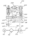
- With reference to the figure, a regulating unit for progressive starting is shown and generally denoted at 210.
- This unit comprises an
inlet 112 to be connected to the compressed-air source, and anoutlet 211 to which the pneumatic circuits to be fed will be connected. Possibly, astage 110 for filtering and condensate elimination will be present in series with the inlet. - A
pressure regulator 212 of the differential type is present between the inlet and outlet, i.e. with a regulating member that is movable by means of the opposite thrusts produced by the outlet pressure of the regulator and the pressure at apiloting input 213. Such a type of valve can be easily conceived by a person skilled in the art. - Connected upstream of the
regulator 212 is the inlet of asecondary circuit 214 leading to theinlet 230 of apiloting unit 215 for thecommand 213 tovalve 212. - The piloting unit comprises a progressive-
starting device 216 that is fed from theinlet 214 and sends air to thecommand 213 from theoutlet 226. - In particular,
device 216 comprises aninlet duct 217 connected with theinlet 214, possibly through further control members to be described in the following. Duct 217 is divided into amain branch 218 connected with theoutlet 226 through an on-off valve orclosure member 219 pushed to the closed position by aspring 220, and asecondary branch 221 reaching theoutlet 226 through athrottled passage 222. The throttledpassage 222 can be advantageously made in an adjustable manner by means of apin 223 that is axially movable through an adjustinghand grip 224. - A distributor or
slide valve 225 exerts pressure on theclosure member 219 in the opening direction thereof, against the action ofspring 220, due to the pressure to which it is subjected and which is created in theoutlet duct 226. - In this manner, the flow rate established by the pin produces a gradual pressure increase in the outlet duct until the thrust on the side downstream of the
closure member 219 exceeds the thrust on the upstream side and the closure member opens themain duct 218 to the outlet. It is apparent that pressure variation on theoutlet 226 is used to accordingly control operation ofvalve 212 thus producing a corresponding pressure variation in theoutlet line 211. Variation online 211 occurs irrespective of the element connected to such a line. - Thus a perfect progressive starting under any load condition of the line is obtained. Achievement of the condition of full effectiveness of the main circuit is also ensured irrespective of the presence or not of possible small pressure leakages in the main circuit itself.
- At this point it is apparent that the aims of the invention have been reached by providing a progressive-starting unit in which the true progressive starter acts on piloting of a valve instead of being directly placed on the main line, as it happens in the known art.
- Such a structure also offers other advantages. The
progressive starter 216 must be sized for the pilot flow rate that is required by regulator 212 (which flow rate is very reduced) and not for the much bigger flow rate of themain line 211. This enables achievement of a progressive-starting unit of a bulkiness much more reduced than that necessary in the technical solutions of the known art. The intrinsic sturdiness of the unit also takes advantage of the above. - The piloting circuit of
valve 212 in which the progressive starter is inserted can also advantageously be a pilot pressure-regulating circuit on the main line. In fact, by placing a knownpilot pressure regulator 227 alongline 214, pressure is stabilized on theoutlet line 211 during normal operation after the progressive starting. In addition, amanual valve 228 and/or anelectric valve 229, of the 3/2 type can also be provided in series with the pilot regulator. Advantageously, as shown in the figure,valve 228 can be inserted in the body of the progressive starter itself.Valves valve 212 in a controlled manner. Thus an efficient piloted regulator is obtained which is of reduced bulkiness and high sturdiness. - Obviously, the above description of an embodiment applying the innovative principles of the present invention is given by way of example only and therefore must not be considered as a limitation of the scope of the patent rights herein claimed.
Claims (7)
- A progressive-starting unit for pneumatic circuits, comprising a line inlet (112) and a line outlet (211) interconnected with each other by a regulating valve (212) that is piloted by a pneumatic piloting inlet (213), characterized by the piloting inlet being controlled by the outlet (226) of a progressive-starting device (216) having an inlet (217) connected upstream of said regulating valve (212).
- A unit as claimed in claim 1, characterized in that the inlet duct (217) of the progressive-starting device is divided into a main branch (218) connected with the outlet (226) through a closure member (219) pushed to the closed position by a spring (220), and a secondary branch (221) reaching the outlet (226) through a throttled passage (222), a control element (225) being provided which acts on the closure member (219) in the opening direction of the latter, against the action of the spring (220), due to the pressure, to which it is submitted, that is created in the outlet duct (226), which means that opening of the closure member is caused when a pre-established pressure is reached in the outlet duct (226).
- A unit as claimed in claim 2, characterized in that the throttled passage (222) is embodied by a pin (223) axially movable by means of an adjusting hand grip (224).
- A unit as claimed in claim 1, characterized in that the inlet of the progressive starting device (216) is connected upstream of the regulating valve (212) through a pilot pressure regulator (227).
- A unit as claimed in claim 1, characterized in that the inlet of the progressive starting device (216) is connected upstream of the regulating valve (212) through a manually controlled on-off valve.
- A unit as claimed in claim 1, characterized in that the inlet of the progressive starting device (216) is connected upstream of the regulating valve (212) through an electrically controlled on-off valve.
- A unit as claimed in claim 1, characterized in that a filtering and condensate discharge device (110) is placed between the line inlet and outlet.
Applications Claiming Priority (2)
| Application Number | Priority Date | Filing Date | Title |
|---|---|---|---|
| ITMI20032562 ITMI20032562A1 (en) | 2003-12-22 | 2003-12-22 | PROGRESSIVE STARTING GROUP FOR PNEUMATIC SYSTEMS |
| ITMI20032562 | 2003-12-22 |
Publications (3)
| Publication Number | Publication Date |
|---|---|
| EP1548288A2 EP1548288A2 (en) | 2005-06-29 |
| EP1548288A3 EP1548288A3 (en) | 2005-11-16 |
| EP1548288B1 true EP1548288B1 (en) | 2006-11-29 |
Family
ID=34531923
Family Applications (1)
| Application Number | Title | Priority Date | Filing Date |
|---|---|---|---|
| EP20040029430 Expired - Lifetime EP1548288B1 (en) | 2003-12-22 | 2004-12-13 | A progressive-starting unit for pneumatic systems |
Country Status (5)
| Country | Link |
|---|---|
| US (1) | US7210393B2 (en) |
| EP (1) | EP1548288B1 (en) |
| AT (1) | ATE347040T1 (en) |
| DE (1) | DE602004003460T2 (en) |
| IT (1) | ITMI20032562A1 (en) |
Families Citing this family (5)
| Publication number | Priority date | Publication date | Assignee | Title |
|---|---|---|---|---|
| ITMI20032563A1 (en) * | 2003-12-22 | 2005-06-23 | Metal Work Spa | INTEGRATED AIR TREATMENT GROUP IN PNEUMATIC SYSTEMS |
| EP2242933B1 (en) * | 2008-02-15 | 2013-01-09 | FESTO AG & Co. KG | Soft start device for compressed air systems and method for operating a soft start device |
| EP2971797A1 (en) * | 2013-03-15 | 2016-01-20 | Ross Operating Valve Company | Control reliable pneumatic energy isolation valve with soft start function |
| KR102342706B1 (en) | 2015-07-08 | 2021-12-22 | 지이 애비에이션 시스템즈 엘엘씨 | Air Starter and Hydrostatic Lock Determination Method |
| DE102021123936B3 (en) * | 2021-09-15 | 2023-01-26 | Aventics Gmbh | safety valve |
Family Cites Families (11)
| Publication number | Priority date | Publication date | Assignee | Title |
|---|---|---|---|---|
| US2998825A (en) * | 1956-01-30 | 1961-09-05 | Master Pneumatic Inc | Device for discharging accumulated water |
| NL113080C (en) * | 1956-04-24 | |||
| US4075928A (en) * | 1974-05-31 | 1978-02-28 | Ross Operating Valve Company | Safety valve for fluid systems |
| JPS55126107A (en) * | 1979-03-19 | 1980-09-29 | Toyooki Kogyo Co Ltd | Controller for compressed-air operated actuator |
| FR2470885A1 (en) * | 1979-11-30 | 1981-06-12 | Telemecanique Electrique | PROGRESSIVE PNEUMATIC STARTER AND CIRCUIT FOR ITS IMPLEMENTATION |
| US4402254A (en) * | 1980-12-01 | 1983-09-06 | La Telemecanique Electrique | Pneumatic starter device |
| FR2511448B1 (en) * | 1981-08-14 | 1986-12-12 | Compair Climax Sa | MODULAR SYSTEM FOR DISPENSING A FLUID UNDER PRESSURE OF CONTROL OF A MOTOR DEVICE COMPRISING AT LEAST ONE MAIN VALVE AND AT LEAST ONE AUXILIARY UNIT SUCH AS A SOFT STARTER OR DRAIN BLOCKER, MOUNTED UPSTREAM OF THE DISTRIBUTOR |
| SE451153B (en) * | 1986-01-20 | 1987-09-07 | Dominator Ab | SET TO CHANGE PRESSURE IN PNEUMATIC OR HYDRAULIC SYSTEM AND DEVICE TO PERFORM THE SET |
| US5038813A (en) * | 1990-05-21 | 1991-08-13 | Rossow David E | Pneumatic starter device |
| JPH086727B2 (en) * | 1991-04-09 | 1996-01-29 | エスエムシー株式会社 | Slow start valve |
| US5669422A (en) * | 1995-04-07 | 1997-09-23 | Ckd Corporation | Slow start valve |
-
2003
- 2003-12-22 IT ITMI20032562 patent/ITMI20032562A1/en unknown
-
2004
- 2004-12-13 EP EP20040029430 patent/EP1548288B1/en not_active Expired - Lifetime
- 2004-12-13 DE DE200460003460 patent/DE602004003460T2/en not_active Expired - Lifetime
- 2004-12-13 AT AT04029430T patent/ATE347040T1/en not_active IP Right Cessation
- 2004-12-15 US US11/013,175 patent/US7210393B2/en not_active Expired - Lifetime
Also Published As
| Publication number | Publication date |
|---|---|
| EP1548288A3 (en) | 2005-11-16 |
| ATE347040T1 (en) | 2006-12-15 |
| ITMI20032562A1 (en) | 2005-06-23 |
| US20050115605A1 (en) | 2005-06-02 |
| DE602004003460D1 (en) | 2007-01-11 |
| DE602004003460T2 (en) | 2007-03-29 |
| EP1548288A2 (en) | 2005-06-29 |
| US7210393B2 (en) | 2007-05-01 |
Similar Documents
| Publication | Publication Date | Title |
|---|---|---|
| US6418956B1 (en) | Pressure controller | |
| US7891375B2 (en) | Softstart valve means | |
| US5337788A (en) | Pneumatic valve with slow start and quick exhaust | |
| EP0559903A4 (en) | Valve device | |
| US20190277496A1 (en) | Solenoid Operated Valve for Reducing Excessive Piping Pressure in a Fluid Distribution System | |
| US10215291B2 (en) | Regulating device | |
| US20010035512A1 (en) | Environmentally friendly electro-pneumatic positioner | |
| GB2059641A (en) | Pipeline surge relief system | |
| US4325677A (en) | Arrangement for the regulation of the output and for limiting the output fluid pressure of an adjustable pump | |
| EP1548288B1 (en) | A progressive-starting unit for pneumatic systems | |
| US6095184A (en) | Pressure regulator with integrated control valve, adjustable downstream pressure build and quick exhaust | |
| US8490647B2 (en) | Fluid pressure control device | |
| JPH09178025A (en) | Two stage type electric hydraulic pressure control valve | |
| US2257171A (en) | Low pressure booster regulator | |
| SE0900866A1 (en) | valve device | |
| US5762468A (en) | Process for protecting a turbocompressor from operation in the unstable working range by means of fittings with two different regulating speeds | |
| US5038813A (en) | Pneumatic starter device | |
| US5669409A (en) | Gas-pressure controller | |
| EP0704623B1 (en) | Delivery control device for hydraulic pumps | |
| US20180024576A1 (en) | Stable Pressure Regulator Apparatus | |
| US5720168A (en) | Control device for a hydraulic pump | |
| US3027902A (en) | Fluid motor throttle valve means responsive to motor exhaust pressure | |
| JPH04297906A (en) | Fluid pressure controller | |
| JP4017280B2 (en) | Fluid supply cutoff equipment | |
| JPH0819922B2 (en) | Variable displacement hydraulic pump controller |
Legal Events
| Date | Code | Title | Description |
|---|---|---|---|
| PUAI | Public reference made under article 153(3) epc to a published international application that has entered the european phase |
Free format text: ORIGINAL CODE: 0009012 |
|
| AK | Designated contracting states |
Kind code of ref document: A2 Designated state(s): AT BE BG CH CY CZ DE DK EE ES FI FR GB GR HU IE IS IT LI LT LU MC NL PL PT RO SE SI SK TR |
|
| AX | Request for extension of the european patent |
Extension state: AL BA HR LV MK YU |
|
| PUAL | Search report despatched |
Free format text: ORIGINAL CODE: 0009013 |
|
| AK | Designated contracting states |
Kind code of ref document: A3 Designated state(s): AT BE BG CH CY CZ DE DK EE ES FI FR GB GR HU IE IS IT LI LT LU MC NL PL PT RO SE SI SK TR |
|
| AX | Request for extension of the european patent |
Extension state: AL BA HR LV MK YU |
|
| 17P | Request for examination filed |
Effective date: 20060330 |
|
| GRAP | Despatch of communication of intention to grant a patent |
Free format text: ORIGINAL CODE: EPIDOSNIGR1 |
|
| AKX | Designation fees paid |
Designated state(s): AT BE BG CH CY CZ DE DK EE ES FI FR GB GR HU IE IS IT LI LT LU MC NL PL PT RO SE SI SK TR |
|
| GRAS | Grant fee paid |
Free format text: ORIGINAL CODE: EPIDOSNIGR3 |
|
| GRAA | (expected) grant |
Free format text: ORIGINAL CODE: 0009210 |
|
| AK | Designated contracting states |
Kind code of ref document: B1 Designated state(s): AT BE BG CH CY CZ DE DK EE ES FI FR GB GR HU IE IS IT LI LT LU MC NL PL PT RO SE SI SK TR |
|
| PG25 | Lapsed in a contracting state [announced via postgrant information from national office to epo] |
Ref country code: LT Free format text: LAPSE BECAUSE OF FAILURE TO SUBMIT A TRANSLATION OF THE DESCRIPTION OR TO PAY THE FEE WITHIN THE PRESCRIBED TIME-LIMIT Effective date: 20061129 Ref country code: PL Free format text: LAPSE BECAUSE OF FAILURE TO SUBMIT A TRANSLATION OF THE DESCRIPTION OR TO PAY THE FEE WITHIN THE PRESCRIBED TIME-LIMIT Effective date: 20061129 Ref country code: BE Free format text: LAPSE BECAUSE OF FAILURE TO SUBMIT A TRANSLATION OF THE DESCRIPTION OR TO PAY THE FEE WITHIN THE PRESCRIBED TIME-LIMIT Effective date: 20061129 Ref country code: AT Free format text: LAPSE BECAUSE OF FAILURE TO SUBMIT A TRANSLATION OF THE DESCRIPTION OR TO PAY THE FEE WITHIN THE PRESCRIBED TIME-LIMIT Effective date: 20061129 Ref country code: IT Free format text: LAPSE BECAUSE OF FAILURE TO SUBMIT A TRANSLATION OF THE DESCRIPTION OR TO PAY THE FEE WITHIN THE PRESCRIBED TIME-LIMIT;WARNING: LAPSES OF ITALIAN PATENTS WITH EFFECTIVE DATE BEFORE 2007 MAY HAVE OCCURRED AT ANY TIME BEFORE 2007. THE CORRECT EFFECTIVE DATE MAY BE DIFFERENT FROM THE ONE RECORDED. Effective date: 20061129 Ref country code: RO Free format text: LAPSE BECAUSE OF FAILURE TO SUBMIT A TRANSLATION OF THE DESCRIPTION OR TO PAY THE FEE WITHIN THE PRESCRIBED TIME-LIMIT Effective date: 20061129 Ref country code: CZ Free format text: LAPSE BECAUSE OF FAILURE TO SUBMIT A TRANSLATION OF THE DESCRIPTION OR TO PAY THE FEE WITHIN THE PRESCRIBED TIME-LIMIT Effective date: 20061129 Ref country code: FI Free format text: LAPSE BECAUSE OF FAILURE TO SUBMIT A TRANSLATION OF THE DESCRIPTION OR TO PAY THE FEE WITHIN THE PRESCRIBED TIME-LIMIT Effective date: 20061129 Ref country code: NL Free format text: LAPSE BECAUSE OF FAILURE TO SUBMIT A TRANSLATION OF THE DESCRIPTION OR TO PAY THE FEE WITHIN THE PRESCRIBED TIME-LIMIT Effective date: 20061129 Ref country code: LI Free format text: LAPSE BECAUSE OF FAILURE TO SUBMIT A TRANSLATION OF THE DESCRIPTION OR TO PAY THE FEE WITHIN THE PRESCRIBED TIME-LIMIT Effective date: 20061129 Ref country code: CH Free format text: LAPSE BECAUSE OF FAILURE TO SUBMIT A TRANSLATION OF THE DESCRIPTION OR TO PAY THE FEE WITHIN THE PRESCRIBED TIME-LIMIT Effective date: 20061129 Ref country code: SK Free format text: LAPSE BECAUSE OF FAILURE TO SUBMIT A TRANSLATION OF THE DESCRIPTION OR TO PAY THE FEE WITHIN THE PRESCRIBED TIME-LIMIT Effective date: 20061129 Ref country code: SI Free format text: LAPSE BECAUSE OF FAILURE TO SUBMIT A TRANSLATION OF THE DESCRIPTION OR TO PAY THE FEE WITHIN THE PRESCRIBED TIME-LIMIT Effective date: 20061129 |
|
| REG | Reference to a national code |
Ref country code: GB Ref legal event code: FG4D |
|
| PG25 | Lapsed in a contracting state [announced via postgrant information from national office to epo] |
Ref country code: IE Free format text: LAPSE BECAUSE OF NON-PAYMENT OF DUE FEES Effective date: 20061213 |
|
| REG | Reference to a national code |
Ref country code: CH Ref legal event code: EP |
|
| PG25 | Lapsed in a contracting state [announced via postgrant information from national office to epo] |
Ref country code: MC Free format text: LAPSE BECAUSE OF NON-PAYMENT OF DUE FEES Effective date: 20061231 |
|
| REG | Reference to a national code |
Ref country code: IE Ref legal event code: FG4D |
|
| REF | Corresponds to: |
Ref document number: 602004003460 Country of ref document: DE Date of ref document: 20070111 Kind code of ref document: P |
|
| PG25 | Lapsed in a contracting state [announced via postgrant information from national office to epo] |
Ref country code: DK Free format text: LAPSE BECAUSE OF FAILURE TO SUBMIT A TRANSLATION OF THE DESCRIPTION OR TO PAY THE FEE WITHIN THE PRESCRIBED TIME-LIMIT Effective date: 20070228 Ref country code: SE Free format text: LAPSE BECAUSE OF FAILURE TO SUBMIT A TRANSLATION OF THE DESCRIPTION OR TO PAY THE FEE WITHIN THE PRESCRIBED TIME-LIMIT Effective date: 20070228 Ref country code: BG Free format text: LAPSE BECAUSE OF FAILURE TO SUBMIT A TRANSLATION OF THE DESCRIPTION OR TO PAY THE FEE WITHIN THE PRESCRIBED TIME-LIMIT Effective date: 20070228 |
|
| PG25 | Lapsed in a contracting state [announced via postgrant information from national office to epo] |
Ref country code: ES Free format text: LAPSE BECAUSE OF FAILURE TO SUBMIT A TRANSLATION OF THE DESCRIPTION OR TO PAY THE FEE WITHIN THE PRESCRIBED TIME-LIMIT Effective date: 20070312 |
|
| PG25 | Lapsed in a contracting state [announced via postgrant information from national office to epo] |
Ref country code: IS Free format text: LAPSE BECAUSE OF FAILURE TO SUBMIT A TRANSLATION OF THE DESCRIPTION OR TO PAY THE FEE WITHIN THE PRESCRIBED TIME-LIMIT Effective date: 20070329 |
|
| PG25 | Lapsed in a contracting state [announced via postgrant information from national office to epo] |
Ref country code: PT Free format text: LAPSE BECAUSE OF FAILURE TO SUBMIT A TRANSLATION OF THE DESCRIPTION OR TO PAY THE FEE WITHIN THE PRESCRIBED TIME-LIMIT Effective date: 20070430 |
|
| NLV1 | Nl: lapsed or annulled due to failure to fulfill the requirements of art. 29p and 29m of the patents act | ||
| ET | Fr: translation filed | ||
| REG | Reference to a national code |
Ref country code: CH Ref legal event code: PL |
|
| PLBE | No opposition filed within time limit |
Free format text: ORIGINAL CODE: 0009261 |
|
| STAA | Information on the status of an ep patent application or granted ep patent |
Free format text: STATUS: NO OPPOSITION FILED WITHIN TIME LIMIT |
|
| 26N | No opposition filed |
Effective date: 20070830 |
|
| PG25 | Lapsed in a contracting state [announced via postgrant information from national office to epo] |
Ref country code: GR Free format text: LAPSE BECAUSE OF FAILURE TO SUBMIT A TRANSLATION OF THE DESCRIPTION OR TO PAY THE FEE WITHIN THE PRESCRIBED TIME-LIMIT Effective date: 20070301 |
|
| PG25 | Lapsed in a contracting state [announced via postgrant information from national office to epo] |
Ref country code: EE Free format text: LAPSE BECAUSE OF FAILURE TO SUBMIT A TRANSLATION OF THE DESCRIPTION OR TO PAY THE FEE WITHIN THE PRESCRIBED TIME-LIMIT Effective date: 20061129 |
|
| PG25 | Lapsed in a contracting state [announced via postgrant information from national office to epo] |
Ref country code: TR Free format text: LAPSE BECAUSE OF FAILURE TO SUBMIT A TRANSLATION OF THE DESCRIPTION OR TO PAY THE FEE WITHIN THE PRESCRIBED TIME-LIMIT Effective date: 20061129 Ref country code: LU Free format text: LAPSE BECAUSE OF NON-PAYMENT OF DUE FEES Effective date: 20061213 Ref country code: HU Free format text: LAPSE BECAUSE OF FAILURE TO SUBMIT A TRANSLATION OF THE DESCRIPTION OR TO PAY THE FEE WITHIN THE PRESCRIBED TIME-LIMIT Effective date: 20070530 |
|
| PG25 | Lapsed in a contracting state [announced via postgrant information from national office to epo] |
Ref country code: CY Free format text: LAPSE BECAUSE OF FAILURE TO SUBMIT A TRANSLATION OF THE DESCRIPTION OR TO PAY THE FEE WITHIN THE PRESCRIBED TIME-LIMIT Effective date: 20061129 |
|
| GBPC | Gb: european patent ceased through non-payment of renewal fee |
Effective date: 20081213 |
|
| PG25 | Lapsed in a contracting state [announced via postgrant information from national office to epo] |
Ref country code: GB Free format text: LAPSE BECAUSE OF NON-PAYMENT OF DUE FEES Effective date: 20081213 |
|
| REG | Reference to a national code |
Ref country code: FR Ref legal event code: PLFP Year of fee payment: 12 |
|
| REG | Reference to a national code |
Ref country code: FR Ref legal event code: PLFP Year of fee payment: 13 |
|
| PGFP | Annual fee paid to national office [announced via postgrant information from national office to epo] |
Ref country code: FR Payment date: 20161111 Year of fee payment: 13 |
|
| REG | Reference to a national code |
Ref country code: FR Ref legal event code: ST Effective date: 20180831 |
|
| PG25 | Lapsed in a contracting state [announced via postgrant information from national office to epo] |
Ref country code: FR Free format text: LAPSE BECAUSE OF NON-PAYMENT OF DUE FEES Effective date: 20180102 |
|
| P01 | Opt-out of the competence of the unified patent court (upc) registered |
Effective date: 20230509 |
|
| PGFP | Annual fee paid to national office [announced via postgrant information from national office to epo] |
Ref country code: DE Payment date: 20231017 Year of fee payment: 20 |
|
| REG | Reference to a national code |
Ref country code: DE Ref legal event code: R071 Ref document number: 602004003460 Country of ref document: DE |