EP1548221A2 - Sliding door mechanism for vehicles - Google Patents
Sliding door mechanism for vehicles Download PDFInfo
- Publication number
- EP1548221A2 EP1548221A2 EP04000605A EP04000605A EP1548221A2 EP 1548221 A2 EP1548221 A2 EP 1548221A2 EP 04000605 A EP04000605 A EP 04000605A EP 04000605 A EP04000605 A EP 04000605A EP 1548221 A2 EP1548221 A2 EP 1548221A2
- Authority
- EP
- European Patent Office
- Prior art keywords
- door
- sub
- closing
- sliding door
- vehicle
- Prior art date
- Legal status (The legal status is an assumption and is not a legal conclusion. Google has not performed a legal analysis and makes no representation as to the accuracy of the status listed.)
- Ceased
Links
Images


Classifications
-
- E—FIXED CONSTRUCTIONS
- E05—LOCKS; KEYS; WINDOW OR DOOR FITTINGS; SAFES
- E05B—LOCKS; ACCESSORIES THEREFOR; HANDCUFFS
- E05B81/00—Power-actuated vehicle locks
- E05B81/12—Power-actuated vehicle locks characterised by the function or purpose of the powered actuators
- E05B81/14—Power-actuated vehicle locks characterised by the function or purpose of the powered actuators operating on bolt detents, e.g. for unlatching the bolt
-
- E—FIXED CONSTRUCTIONS
- E05—LOCKS; KEYS; WINDOW OR DOOR FITTINGS; SAFES
- E05B—LOCKS; ACCESSORIES THEREFOR; HANDCUFFS
- E05B81/00—Power-actuated vehicle locks
- E05B81/12—Power-actuated vehicle locks characterised by the function or purpose of the powered actuators
- E05B81/20—Power-actuated vehicle locks characterised by the function or purpose of the powered actuators for assisting final closing or for initiating opening
- E05B81/22—Power-actuated vehicle locks characterised by the function or purpose of the powered actuators for assisting final closing or for initiating opening by movement of the striker
-
- E—FIXED CONSTRUCTIONS
- E05—LOCKS; KEYS; WINDOW OR DOOR FITTINGS; SAFES
- E05F—DEVICES FOR MOVING WINGS INTO OPEN OR CLOSED POSITION; CHECKS FOR WINGS; WING FITTINGS NOT OTHERWISE PROVIDED FOR, CONCERNED WITH THE FUNCTIONING OF THE WING
- E05F15/00—Power-operated mechanisms for wings
- E05F15/60—Power-operated mechanisms for wings using electrical actuators
- E05F15/603—Power-operated mechanisms for wings using electrical actuators using rotary electromotors
- E05F15/632—Power-operated mechanisms for wings using electrical actuators using rotary electromotors for horizontally-sliding wings
- E05F15/643—Power-operated mechanisms for wings using electrical actuators using rotary electromotors for horizontally-sliding wings operated by flexible elongated pulling elements, e.g. belts, chains or cables
- E05F15/646—Power-operated mechanisms for wings using electrical actuators using rotary electromotors for horizontally-sliding wings operated by flexible elongated pulling elements, e.g. belts, chains or cables allowing or involving a secondary movement of the wing, e.g. rotational or transversal
-
- E—FIXED CONSTRUCTIONS
- E05—LOCKS; KEYS; WINDOW OR DOOR FITTINGS; SAFES
- E05B—LOCKS; ACCESSORIES THEREFOR; HANDCUFFS
- E05B81/00—Power-actuated vehicle locks
- E05B81/12—Power-actuated vehicle locks characterised by the function or purpose of the powered actuators
- E05B81/20—Power-actuated vehicle locks characterised by the function or purpose of the powered actuators for assisting final closing or for initiating opening
- E05B81/21—Power-actuated vehicle locks characterised by the function or purpose of the powered actuators for assisting final closing or for initiating opening with means preventing or detecting pinching of objects or body parts
-
- E—FIXED CONSTRUCTIONS
- E05—LOCKS; KEYS; WINDOW OR DOOR FITTINGS; SAFES
- E05Y—INDEXING SCHEME ASSOCIATED WITH SUBCLASSES E05D AND E05F, RELATING TO CONSTRUCTION ELEMENTS, ELECTRIC CONTROL, POWER SUPPLY, POWER SIGNAL OR TRANSMISSION, USER INTERFACES, MOUNTING OR COUPLING, DETAILS, ACCESSORIES, AUXILIARY OPERATIONS NOT OTHERWISE PROVIDED FOR, APPLICATION THEREOF
- E05Y2201/00—Constructional elements; Accessories therefor
- E05Y2201/60—Suspension or transmission members; Accessories therefor
- E05Y2201/622—Suspension or transmission members elements
- E05Y2201/644—Flexible elongated pulling elements
- E05Y2201/654—Cables
-
- E—FIXED CONSTRUCTIONS
- E05—LOCKS; KEYS; WINDOW OR DOOR FITTINGS; SAFES
- E05Y—INDEXING SCHEME ASSOCIATED WITH SUBCLASSES E05D AND E05F, RELATING TO CONSTRUCTION ELEMENTS, ELECTRIC CONTROL, POWER SUPPLY, POWER SIGNAL OR TRANSMISSION, USER INTERFACES, MOUNTING OR COUPLING, DETAILS, ACCESSORIES, AUXILIARY OPERATIONS NOT OTHERWISE PROVIDED FOR, APPLICATION THEREOF
- E05Y2201/00—Constructional elements; Accessories therefor
- E05Y2201/60—Suspension or transmission members; Accessories therefor
- E05Y2201/622—Suspension or transmission members elements
- E05Y2201/658—Members cooperating with flexible elongated pulling elements
- E05Y2201/668—Pulleys; Wheels
-
- E—FIXED CONSTRUCTIONS
- E05—LOCKS; KEYS; WINDOW OR DOOR FITTINGS; SAFES
- E05Y—INDEXING SCHEME ASSOCIATED WITH SUBCLASSES E05D AND E05F, RELATING TO CONSTRUCTION ELEMENTS, ELECTRIC CONTROL, POWER SUPPLY, POWER SIGNAL OR TRANSMISSION, USER INTERFACES, MOUNTING OR COUPLING, DETAILS, ACCESSORIES, AUXILIARY OPERATIONS NOT OTHERWISE PROVIDED FOR, APPLICATION THEREOF
- E05Y2600/00—Mounting or coupling arrangements for elements provided for in this subclass
- E05Y2600/10—Adjustable
-
- E—FIXED CONSTRUCTIONS
- E05—LOCKS; KEYS; WINDOW OR DOOR FITTINGS; SAFES
- E05Y—INDEXING SCHEME ASSOCIATED WITH SUBCLASSES E05D AND E05F, RELATING TO CONSTRUCTION ELEMENTS, ELECTRIC CONTROL, POWER SUPPLY, POWER SIGNAL OR TRANSMISSION, USER INTERFACES, MOUNTING OR COUPLING, DETAILS, ACCESSORIES, AUXILIARY OPERATIONS NOT OTHERWISE PROVIDED FOR, APPLICATION THEREOF
- E05Y2900/00—Application of doors, windows, wings or fittings thereof
- E05Y2900/50—Application of doors, windows, wings or fittings thereof for vehicles
- E05Y2900/53—Type of wing
- E05Y2900/531—Doors
Definitions
- the present invention relates to the operation of sliding doors. More particularly, the invention provides a mechanism comprising two sub-mechanisms for opening and closing a sliding vehicle door of the type commonly found in vans, buses and commercial vehicles.
- Vehicle sliding doors are often manually operated, which is quite satisfactory where the driver or an assistant dismounts for this purpose and operation is infrequent.
- a powered mechanism is however preferable where door operation is frequent and/or the driver is not to dismount during door operation.
- Today vans and minibuses are commonly used to transport typically 6 -22 passengers or delivery vans, and on taxis running on city routes door opening is frequent, and occurs on the side opposite the driver's seat and in a situation where the driver needs to remain in place.
- Clearly, such arrangement calls for a power-operated door.
- Vehicle hinged doors can be pneumatically operated, but the long movement of a sliding door is more suitable for electrical operation.
- a flexible hauling element is connected to the door via a carriage running in a drive rail.
- a basic problem with prior art door closures is that the motor provided is called upon to carry out two quite different tasks.
- the closing of car doors is so to say a two mode operation. In the first mode the door is moved to the closing position. In the second mode the locking mechanism attracts the locking pin to perform a latching operation which, so to say, seals the door. In order to open a door the first operation is to release the locking pin and the second to move the door to the open position. During door operation a fast, long, longitudinal stroke is required for covering/uncovering the open section of the vehicle side and to catch the locking pin.
- a further object of the present invention is to provide a controller for controlling all functions of operating the door.
- the present invention achieves the above objects by providing a mechanism for electrically opening and closing a sliding door on the side of a vehicle, said mechanism comprising a first and a second sub-mechanism, each of said sub-mechanisms being driven by its own electric motor, said first sub-mechanism being arranged to move said door in a direction parallel to the direction of vehicle motion, and said second sub-mechanism being arranged to move said door in a direction substationaly perpendicular to the direction of vehicle motion for latching and unlatching of said door.
- an assembly mechanism for electrically opening and closing a sliding door attached to the body of the vehicle wherein said first sub mechanism comprises a cable drum driven by a geared electric motor, the extremities of the cable being anchored to said door and a second sub mechanism geared electric motor drives directly or indirectly a mechanism to operate said latching/unlatching of the door.
- a controller for controlling and synchronizing the two sub-mechanism and for controlling the movement of the door and the latching and unlatching thereof.
- the door is operated by RF signals.
- the novel device of the present invention serves to relieve strain on the driver or assistant whether the vehicle is outfitted for carrying passengers or goods.
- the electric motors used are powered by the vehicle electric system. Each motor is designed to drive at an optimum point on its speed/torque graph, and the design of one motor and drive system in no way inhibits design of the other.
- the motors and drive are accessible for maintenance.
- the present invention refers to moving and latching the door. After closure of the door the door may be locked using any prior-art method.
- the lock is electrically operated, being easiest to merge into the door operation system. For safety purposes it is possible to open the door by hand if power is unavailable or there is a breakdown or accident.
- the apparatus of the present invention may be used with these - or other- types of emergency drive release mechanisms, which are not described in the present text. Likewise the whole assembly could be disconnected to enable operating the door manually.
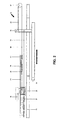
- FIG. 1 a van 1 provided with a sliding door 14 to close opening 4.
- the original van's locking pin member 6 is replaced by a movable mechanism 60 (FIG. 5 and 6).
- Contacts 15 are adapted to charge the battery on the hand and enable the controller to recognize the position of the door on the other hand.
- FIG. 2 and FIG. 3 There is seen in FIG. 2 and FIG. 3 a first sub-mechanism 12 for electrically opening and closing a sliding door 14 on the side of a vehicle.
- the first sub-mechanism 12 is a part of the mechanism assembly 10 represented in FIG. 7.
- a geared electric motor 18 drives a cable drum 20.
- both extremities 22, 24 of the cable 26 are firmly anchored to the sliding door 14 itself, or as seen in the figure, anchored to a beam 28 projecting therefrom, the door 14 is pulled longitudinally along prior-art rails (not seen) accessible along the outer side of the vehicle to close/open the vehicle aperture 4.
- a bracket 44 rigidly attached to the vehicle pulls the door 14 in a direction parallel to the direction of vehicle motion, to open/close door 14.
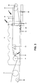
- first sub-mechanism 50 for electrically opening and closing a sliding vehicle door 14.
- the first sub-mechanism 50 is provided with two spring-loaded tensioner pulleys 34, 38 in contact with the cable 26, as seen in the previous figures.
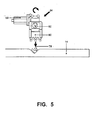
- FIG. 5 illustrates a second sub-mechanism 54 for electrically opening and closing a sliding door 14.
- an electrical signal generated by pressure on the "OPEN" button 56 (see FIG. 7), accessible to the vehicle driver, will activate the second sub-mechanism 54 which comprises a geared electric motor 58 driving an eccentrically-mounted excenter element 60 which replaced the original locking pin member 6 and adapted to engage latching mechanism 78.
- Latching mechanism 78 is released either in a conventional manner or by release mechanism 8 (FIG. 1), which enable the first sub-mechanism to slide-open the door.
- Seen in FIG. 6 is a preferred embodiment of a second sub-mechanism 66 which is useful for vehicles wherein lateral space is limited.
- the sub-mechanism 66 electrically moves the vehicle sliding door 14 between its inner, latched position and its outer position allowing longitudinal travel.
- a geared electric motor 68 drives a rack 70 and pinion 72.
- the rack 70 drives a crank mechanism 74 to operate the latching/unlatching slide 76.
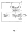
- FIG. 7 is a diagrammatic representation of the mechanism 10.
- the mechanism 10 comprises a first 12 and a second sub-mechanism 54, each of the sub-mechanisms being driven by its own electric motor which have been described.
- the Mechanism further comprises a release mechanism 8 and a transmitter 9.
Landscapes
- Power-Operated Mechanisms For Wings (AREA)
- Lock And Its Accessories (AREA)
- Support Devices For Sliding Doors (AREA)
Abstract
Description
More particularly, the invention provides a mechanism comprising two sub-mechanisms for opening and closing a sliding vehicle door of the type commonly found in vans, buses and commercial vehicles.
In US Patent No. 4,289,995 Sorber et al. claim to an automatic motor-driven door closer provided with a slip clutch. By means of Zener diodes overspeeding of the motor is prevented. A slip clutch prevents motor overload.
Naganuma describes a system for controlling a vehicle power sliding door in US Patent 6,525,499 and application20010024093. The system uses a FET and PWM to regulate the motor, claiming to reduce the size of the power components needed.
Fukumoto et al disclose an opening and closing device for a sliding vehicle door in US Patent No. 6,530,619. The motor and cable drum are both to be built into the door, thus imposing strict size and power limits on these components. The system requires some flexible cable arrangement to power the motor.
A method for operating a vehicle power sliding door is disclosed by Long et al. in US Patent No. 6,588,829. The patent is primarily concerned with monitoring and control for preventing collision of the door with obstructions, and provides interconnection with a child guard mechanism.
Yokomori discloses a control method for sliding door operation in US Patent No. 6,618,997. The method entails the use of both an auxiliary wire drum brake and a clutch.
In patent application No US 2002/0112404A1 Minh Au Truong discloses a drive for a vehicle sliding door. A mechanical member transmits a torque provided by a slave motor. A flexible hauling element is connected to the door via a carriage running in a drive rail.
A basic problem with prior art door closures is that the motor provided is called upon to carry out two quite different tasks. The closing of car doors is so to say a two mode operation. In the first mode the door is moved to the closing position. In the second mode the locking mechanism attracts the locking pin to perform a latching operation which, so to say, seals the door. In order to open a door the first operation is to release the locking pin and the second to move the door to the open position. During door operation a fast, long, longitudinal stroke is required for covering/uncovering the open section of the vehicle side and to catch the locking pin. With regard to latching/unlatching, second mode, a short high-resistance lateral stroke is required. It is clear that prior art devices using a single motor for so to say both actions cannot perform in an optimum manner, and result in a requirement for superfluous electronic controls and oversized motors and gearing.
While it is possible to mount an electric motor inside the door, there are many disadvantages of doing so, such as space and power restrictions, the need for flexible power feed, and difficult maintenance access.
All known arrangement are mounted within the door or the side wall of the vehicle thus major changes are required, more so, electrical power must be supplied thus special wiring is required such wring supplying electric power to the components inside the door and for means provided for prevention of injury to users.
It is a further object of the present invention to position the assembly on the vehicle body to provide improved design flexibility and better maintenance access.
A further object of the present invention is to provide a sliding door without an electrical cable connection.
It is finally an object of the present application to provide a stand alone assembly mechanism which could be mounted on any vehicle without the need to change the structure by mounting it underneath the vehicle and just by replacing the locking pin member.
The electric motors used are powered by the vehicle electric system. Each motor is designed to drive at an optimum point on its speed/torque graph, and the design of one motor and drive system in no way inhibits design of the other. The motors and drive are accessible for maintenance.
The present invention refers to moving and latching the door. After closure of the door the door may be locked using any prior-art method. Preferably the lock is electrically operated, being easiest to merge into the door operation system.
For safety purposes it is possible to open the door by hand if power is unavailable or there is a breakdown or accident. This can be arranged by various means, for example by attaching the beam driving the door in a detachable manner, by designing the cable anchors to be removable, by adding slip clutches, or separating the motor from the pully in a mechanical manner. The apparatus of the present invention may be used with these - or other- types of emergency drive release mechanisms, which are not described in the present text. Likewise the whole assembly could be disconnected to enable operating the door manually.
A geared
With reference to the rest of the figures, similar reference numerals have been used to identify similar parts.
A geared
Assuming the
In order to open the door, pressure on button 56 (see FIG.7) will cause the controller to generate a signal to the second sub-mechanism which will activate
It would be within the scope of the invention to provide micro-switches on the door handle to enable the opening or closing of the door from the out side or inside. The switches operate in parallel to push
The controller (not seen) is monitoring the torque required for moving the door to the closing position, to the slightest resistance - due to an obstruction - a signal generated by the controller will reverse the movement of the door. The signals to the motors will preferably transmitted by an RF transmitter.
FIG. 7 is a diagrammatic representation of the
Claims (10)
- A mechanism for electrically opening and closing a sliding door on the side of a vehicle, said mechanism comprising a first and a second sub-mechanism, each of said sub-mechanisms being driven by its own electric motor, said first sub-mechanism being arranged to move said door in a direction parallel to the direction of vehicle motion to open/close said door, and said second sub-mechanism being arranged to move said door in a direction substantially perpendicular to the direction of vehicle motion for latching and unlatching of said door.
- The mechanism for electrically opening and closing a sliding door as claimed in claim 1, wherein said first sub mechanism comprises a cable drum driven by a geared electric motor, the extremities of said cable being anchored to said door.
- The mechanism for electrically opening and closing a sliding door as claimed in claim 2, further provided with at least one spring-loaded tensioner pulley in contact with said cable.
- The mechanism for electrically opening and closing a sliding door as claimed in claim 1, wherein said mechanism is mounted underneath the vehicle.
- The mechanism for electrically opening and closing a sliding door as claimed in claim 1, wherein said second sub-mechanism comprises a geared electric motor driving an eccentrically-mounted element driving a latching/unlatching slide.
- The mechanism for electrically opening and closing a sliding door as claimed in claim 5, wherein said geared electric motor drives a rack and pinion and said rack drives a crank mechanism to operate said latching/unlatching slide.
- The mechanism for electrically opening and closing a sliding door as claimed in claim 1, wherein there is further provided a receiver/transmitter mounted within the door.
- The mechanism for electrically opening and closing a sliding door as claimed in any of claims 1 to 7 wherein a controller is provided to control and synchronize the mechanism.
- The mechanism for electrically opening and closing a sliding door as claimed in claim 7 wherein said controller generates RF signals to said receiver/transmitter and/or vise versa.
- A mechanism for electrically opening and closing a sliding door on the side of a vehicle, said mechanism comprising a first and a second sub-mechanism, each of said sub-mechanisms being driven by its own electric motor, substantially as described hereinbefore and with reference to the accompanying drawings.
Applications Claiming Priority (2)
| Application Number | Priority Date | Filing Date | Title |
|---|---|---|---|
| IL15953303 | 2003-12-23 | ||
| IL159533A IL159533A0 (en) | 2003-12-23 | 2003-12-23 | Electrically-operated sliding door mechanism |
Publications (2)
| Publication Number | Publication Date |
|---|---|
| EP1548221A2 true EP1548221A2 (en) | 2005-06-29 |
| EP1548221A3 EP1548221A3 (en) | 2005-12-28 |
Family
ID=34531849
Family Applications (1)
| Application Number | Title | Priority Date | Filing Date |
|---|---|---|---|
| EP04000605A Ceased EP1548221A3 (en) | 2003-12-23 | 2004-01-14 | Sliding door mechanism for vehicles |
Country Status (2)
| Country | Link |
|---|---|
| EP (1) | EP1548221A3 (en) |
| IL (1) | IL159533A0 (en) |
Cited By (6)
| Publication number | Priority date | Publication date | Assignee | Title |
|---|---|---|---|---|
| WO2006086892A1 (en) * | 2005-02-18 | 2006-08-24 | Magna Closures Inc. | Compact cable drive power sliding door mechanism |
| US7770961B2 (en) | 2006-02-20 | 2010-08-10 | Magna Closures Inc. | Compact cable drive power sliding door mechanism |
| US7810282B2 (en) | 2006-09-25 | 2010-10-12 | Magna Closures Inc. | Belt-driven rack gear power sliding door |
| US7866732B2 (en) | 2007-02-28 | 2011-01-11 | Magna Closures Inc. | Compact cable drive power sliding door mechanism |
| EP2449193A4 (en) * | 2009-06-12 | 2014-12-03 | Raymond A & Cie | Power cinching striker |
| CN110359806A (en) * | 2019-06-21 | 2019-10-22 | 芜湖莫森泰克汽车科技股份有限公司 | A kind of driving mechanism for realizing sliding door of automobile L-type track |
Family Cites Families (3)
| Publication number | Priority date | Publication date | Assignee | Title |
|---|---|---|---|---|
| DE3401842A1 (en) * | 1984-01-20 | 1985-08-01 | Erich 8650 Kulmbach Pöhlmann | Motor-vehicle door lock, bonnet lock or the like |
| US5239779A (en) * | 1990-03-22 | 1993-08-31 | Masco Industries, Inc. | Control apparatus for powered vehicle door systems |
| US5806246A (en) * | 1995-02-28 | 1998-09-15 | Nippon Cable System Inc. | Powered sliding-door system and actuating devices for the same |
-
2003
- 2003-12-23 IL IL159533A patent/IL159533A0/en unknown
-
2004
- 2004-01-14 EP EP04000605A patent/EP1548221A3/en not_active Ceased
Cited By (6)
| Publication number | Priority date | Publication date | Assignee | Title |
|---|---|---|---|---|
| WO2006086892A1 (en) * | 2005-02-18 | 2006-08-24 | Magna Closures Inc. | Compact cable drive power sliding door mechanism |
| US7770961B2 (en) | 2006-02-20 | 2010-08-10 | Magna Closures Inc. | Compact cable drive power sliding door mechanism |
| US7810282B2 (en) | 2006-09-25 | 2010-10-12 | Magna Closures Inc. | Belt-driven rack gear power sliding door |
| US7866732B2 (en) | 2007-02-28 | 2011-01-11 | Magna Closures Inc. | Compact cable drive power sliding door mechanism |
| EP2449193A4 (en) * | 2009-06-12 | 2014-12-03 | Raymond A & Cie | Power cinching striker |
| CN110359806A (en) * | 2019-06-21 | 2019-10-22 | 芜湖莫森泰克汽车科技股份有限公司 | A kind of driving mechanism for realizing sliding door of automobile L-type track |
Also Published As
| Publication number | Publication date |
|---|---|
| IL159533A0 (en) | 2009-02-11 |
| EP1548221A3 (en) | 2005-12-28 |
Similar Documents
| Publication | Publication Date | Title |
|---|---|---|
| US5168666A (en) | Drive device of slide door | |
| EP1116850B1 (en) | Rear gate opening and closing apparatus for vehicle | |
| US11002059B2 (en) | Electric door opener for multi-door trailer | |
| US6119402A (en) | Power sliding rear window | |
| US6087794A (en) | Automatic open-and-close system for a vehicle slide door | |
| US6374938B2 (en) | Seat belt control device | |
| RU2673586C1 (en) | Door system with electric drive module for vehicle | |
| EP1157182B1 (en) | Power sliding vehicle door | |
| US6802154B1 (en) | Automatic sliding door opening and closing system with a releasing mechanism for fixably and releasably attaching a vehicle door to a belt drive system | |
| US8567129B2 (en) | Vehicle door control method and system therefor | |
| CN103132816A (en) | Emergency release device for a vehicle trunk | |
| US10669764B2 (en) | Rail module with cable conduits for window regulator systems | |
| US20080100085A1 (en) | Selectively detachable tailgate hinge assembly | |
| US20040123525A1 (en) | Door control device | |
| EP1548221A2 (en) | Sliding door mechanism for vehicles | |
| US5688019A (en) | Door and window drive clutch assembly | |
| US3971570A (en) | Belt locking arrangement for a passive belt system for automobiles | |
| US12060735B2 (en) | Vehicle door operation device | |
| JP4643064B2 (en) | Unlocking structure for side sliding doors for railway vehicles | |
| JPH0214217B2 (en) | ||
| EP1167675B1 (en) | Automatic sliding door opening/closing system | |
| JP3851117B2 (en) | Automatic opening and closing device for vehicle door | |
| RU56924U1 (en) | DEVICE FOR OPENING AND CLOSING A SLIDING DOOR OF A VEHICLE | |
| KR20040016736A (en) | Safety locking apparatus for power sliding door of vehicle | |
| KR100448500B1 (en) | A center console locking equipment by using magnetic repelling power |
Legal Events
| Date | Code | Title | Description |
|---|---|---|---|
| PUAI | Public reference made under article 153(3) epc to a published international application that has entered the european phase |
Free format text: ORIGINAL CODE: 0009012 |
|
| AK | Designated contracting states |
Kind code of ref document: A2 Designated state(s): AT BE BG CH CY CZ DE DK EE ES FI FR GB GR HU IE IT LI LU MC NL PT RO SE SI SK TR |
|
| AX | Request for extension of the european patent |
Extension state: AL LT LV MK |
|
| PUAL | Search report despatched |
Free format text: ORIGINAL CODE: 0009013 |
|
| AK | Designated contracting states |
Kind code of ref document: A3 Designated state(s): AT BE BG CH CY CZ DE DK EE ES FI FR GB GR HU IE IT LI LU MC NL PT RO SE SI SK TR |
|
| AX | Request for extension of the european patent |
Extension state: AL LT LV MK |
|
| 17P | Request for examination filed |
Effective date: 20060627 |
|
| AKX | Designation fees paid |
Designated state(s): AT BE BG CH CY CZ DE DK EE ES FI FR GB GR HU IE IT LI LU MC NL PT RO SE SI SK TR |
|
| 17Q | First examination report despatched |
Effective date: 20061211 |
|
| 17Q | First examination report despatched |
Effective date: 20061211 |
|
| STAA | Information on the status of an ep patent application or granted ep patent |
Free format text: STATUS: THE APPLICATION HAS BEEN REFUSED |
|
| 18R | Application refused |
Effective date: 20090516 |