EP1548198A1 - Schallrichtungspaneel für Schallkonditionierung - Google Patents
Schallrichtungspaneel für Schallkonditionierung Download PDFInfo
- Publication number
- EP1548198A1 EP1548198A1 EP04078315A EP04078315A EP1548198A1 EP 1548198 A1 EP1548198 A1 EP 1548198A1 EP 04078315 A EP04078315 A EP 04078315A EP 04078315 A EP04078315 A EP 04078315A EP 1548198 A1 EP1548198 A1 EP 1548198A1
- Authority
- EP
- European Patent Office
- Prior art keywords
- panel
- sound
- cells
- chambers
- zone
- Prior art date
- Legal status (The legal status is an assumption and is not a legal conclusion. Google has not performed a legal analysis and makes no representation as to the accuracy of the status listed.)
- Withdrawn
Links
- 230000003750 conditioning effect Effects 0.000 title claims abstract description 7
- 210000004027 cell Anatomy 0.000 abstract 3
- 210000003850 cellular structure Anatomy 0.000 abstract 1
- 230000000694 effects Effects 0.000 description 11
- 239000002250 absorbent Substances 0.000 description 4
- 239000000463 material Substances 0.000 description 4
- 238000004519 manufacturing process Methods 0.000 description 3
- 238000013016 damping Methods 0.000 description 2
- 206010042674 Swelling Diseases 0.000 description 1
- 230000002745 absorbent Effects 0.000 description 1
- 230000006835 compression Effects 0.000 description 1
- 238000007906 compression Methods 0.000 description 1
- 230000003247 decreasing effect Effects 0.000 description 1
- 230000004048 modification Effects 0.000 description 1
- 238000012986 modification Methods 0.000 description 1
- 230000008961 swelling Effects 0.000 description 1
Images


Classifications
-
- E—FIXED CONSTRUCTIONS
- E04—BUILDING
- E04B—GENERAL BUILDING CONSTRUCTIONS; WALLS, e.g. PARTITIONS; ROOFS; FLOORS; CEILINGS; INSULATION OR OTHER PROTECTION OF BUILDINGS
- E04B1/00—Constructions in general; Structures which are not restricted either to walls, e.g. partitions, or floors or ceilings or roofs
- E04B1/62—Insulation or other protection; Elements or use of specified material therefor
- E04B1/74—Heat, sound or noise insulation, absorption, or reflection; Other building methods affording favourable thermal or acoustical conditions, e.g. accumulating of heat within walls
- E04B1/82—Heat, sound or noise insulation, absorption, or reflection; Other building methods affording favourable thermal or acoustical conditions, e.g. accumulating of heat within walls specifically with respect to sound only
- E04B1/84—Sound-absorbing elements
- E04B1/86—Sound-absorbing elements slab-shaped
-
- E—FIXED CONSTRUCTIONS
- E01—CONSTRUCTION OF ROADS, RAILWAYS, OR BRIDGES
- E01F—ADDITIONAL WORK, SUCH AS EQUIPPING ROADS OR THE CONSTRUCTION OF PLATFORMS, HELICOPTER LANDING STAGES, SIGNS, SNOW FENCES, OR THE LIKE
- E01F8/00—Arrangements for absorbing or reflecting air-transmitted noise from road or railway traffic
- E01F8/0005—Arrangements for absorbing or reflecting air-transmitted noise from road or railway traffic used in a wall type arrangement
- E01F8/0041—Free-standing grates
-
- E—FIXED CONSTRUCTIONS
- E01—CONSTRUCTION OF ROADS, RAILWAYS, OR BRIDGES
- E01F—ADDITIONAL WORK, SUCH AS EQUIPPING ROADS OR THE CONSTRUCTION OF PLATFORMS, HELICOPTER LANDING STAGES, SIGNS, SNOW FENCES, OR THE LIKE
- E01F8/00—Arrangements for absorbing or reflecting air-transmitted noise from road or railway traffic
- E01F8/0005—Arrangements for absorbing or reflecting air-transmitted noise from road or railway traffic used in a wall type arrangement
- E01F8/0047—Arrangements for absorbing or reflecting air-transmitted noise from road or railway traffic used in a wall type arrangement with open cavities, e.g. for covering sunken roads
- E01F8/0076—Cellular, e.g. as wall facing
-
- E—FIXED CONSTRUCTIONS
- E04—BUILDING
- E04B—GENERAL BUILDING CONSTRUCTIONS; WALLS, e.g. PARTITIONS; ROOFS; FLOORS; CEILINGS; INSULATION OR OTHER PROTECTION OF BUILDINGS
- E04B1/00—Constructions in general; Structures which are not restricted either to walls, e.g. partitions, or floors or ceilings or roofs
- E04B1/62—Insulation or other protection; Elements or use of specified material therefor
- E04B1/74—Heat, sound or noise insulation, absorption, or reflection; Other building methods affording favourable thermal or acoustical conditions, e.g. accumulating of heat within walls
- E04B2001/742—Use of special materials; Materials having special structures or shape
- E04B2001/748—Honeycomb materials
Definitions
- the invention relates to a sound-directing panel for sound conditioning.
- a possible application of the invention is for the reduction of a sound level generated in closed or open environments, and/or for insulating specified zones from others in which sound is generated.
- the prior art includes panels, known as sound-absorbent panels, which comprise a covering with a layer of material able to absorb and therefore trap a part of the sound waves striking it.
- the main aim of the present invention is to provide a panel which is able to considerably reduce the sound level, while at the same time offering dimensions and production costs which are the same as or less than those for traditional panels.
- the panel (denoted in its entirety by P in the figures) comprises a cell structure, formed by a plurality of cells 10 having tubular chambers which are frontally open, adjacent to one another, each being laterally delimited by relatively thin walls 11 and having axes which are substantially parallel to one another.
- the dimensions of the transversal section and the length of the chambers of the cells 10 are such as to define corridors able to channel the sound hitting the panel and direct it in the direction of the axes of the cell chambers.
- each cell 10 has a constant transversal section and a cylindrical lateral surface 11, meaning that the surface can be curved (for example in the case of a circular section) or prismatic (for example having a polygon section), and the chambers have a constant or nearly constant transversal section.
- the section of the cell 10 can be shaped in several different ways, rectangular, polygonal, circular, regular or not regular, and so on.
- the axis A of the chamber of the cells 10 can be straight; alternatively it is curved or zigzagged; also, the size of the transversal sections can vary, in particular by gradually increasing or decreasing.
- the bottom surface of the cells 10 is closed, for example by a bottom wall 12.
- the corridor defined by the cells 10 is open both frontally and posteriorly, and the axis A is curved.
- Figures 1, 2 and 2A show a panel which develops on a vertical plane; however the panel of the invention may develop on surfaces having different geometrical forms (inclined, horizontal, curved etc.) according to needs or type of application.
- FIG. 3 schematically illustrates the above-described phenomenon.
- a first wave exits from a sound source S and strikes the open front surface of a cell 10a of the panel P, in a straight trajectory R1; the wave enters the cell 10a and is channelled along the corridor up to the bottom 12 thereof, where it is reflected by the bottom 12 and exits in a trajectory R1' which coincides with the axis A of the cell 10a.
- the most probable interpretation of the phenomenon is that the sound wave, once having entered the cell 10 chamber, is channelled, probably with several reflections along the lateral walls, up until it strikes the bottom wall 12 and is reflected therefrom and sent out of the cell 10 with a "megaphone" effect, i.e. directed and issued according to the direction of the axis A of the cell 10; during this phenomenon, the surfaces of the walls 11 condition the sound wave like a megaphone and confer on it a more or less constant direction, being the direction of the axis A of the cell 10.
- the dimensions of the chamber of the cell 10 i.e. the size of the transversal section and the depth of the chamber, must respect certain conditions.
- a first condition is that the transversal section must have a diameter which is preferably in the same order as the wave to be treated; thus, as we are dealing with sound waves, whose minimum values are of a few centimetres, excellent results are obtained with a section whose diameter does not exceed five centimetres. Satisfactory results have been obtained, however, with values above this, up to nine centimetres.
- a further condition to be respected is that the depth (axial dimension) of the cell 10 must have a value which is possibly not smaller than the diameter of the transversal section, as the bigger the relationship between the depth and the diameter, the more effective the conditioning which the sound wave receives and therefore the better the megaphone effect.
- the panel in practice, will be dimensioned according to applicational needs, as the best compromise between the conditions and the above-described factors.
- the front faces of the cells 10 can be aligned on a same geometrical surface to give rise to a flat front surface, as illustrated in figures 1 and 2.
- the front mouths of the cells 10 can be cut to 90° with respect to the axis A of the cell 10, as illustrated in figure 2A.
- a practical preferred shape is that the cell 10 section is polygonal (for example, square, or hexagonal as in the case illustrated in figure 1), and the cells 10 should be reciprocally adjacent, in order to entirely occupy the front panel surface, offering the greatest possible area of empty surface.
- FIG. 4 schematically represents this scenario; the sound wave issued from the source S hits the cell 10d with a trajectory R4 that forms, with the front plane of the panel, an angle B which is relatively small, such that when the wave strikes the lateral wall of the cell, instead of being reflected into the cell and being "captured” thereby, it is reflected in an external direction; in this case the "megaphone effect" does not occur and the panel behaves like a usual reflecting surface.
- the inclination of the sound wave with respect to the frontal surface of the panel has to be taken into effect.
- a further phenomenon encountered in the panel of the invention is that the sound reflected by the panel P, though composed of elements whose surfaces are not intrinsically sound absorbent, is subject to an energy-damping effect with respect to a sound that is simply reflected off another type of non-sound-absorbent material surface.
- the explanation of this phenomenon is that in the cell 10 chamber, the part of the sound wave that is reflected by the bottom 12 interferes with the part of sound wave that follows, which enters in the chamber in the opposite direction, and the portions of sound under compression combine with the portions of sound under depression, with a cancelling-out effect. In the majority of cases there is not a total reduction of sound, but there is most certainly a very considerable reduction.
- this sound-reducing effect can be increased by placing a known-type sound-absorbent material in the posterior zone of the cell 10 chambers.
- the sound wave striking the front surface of the panel P whatever the inclination of the trajectory thereof with respect to the panel, is channelled by the cells 10 and issued in a plurality of waves, parallel to one another and having a direction coinciding with the axes of the cells 10; during this phenomenon, the surfaces of the walls 11 condition the sound wave like a megaphone and confer thereon a direction which is practically constant in the direction of the axis A of the cell 10.
- the sound wave enters the panel from one side and exits from the other side. It may be worthwhile using cells 10 having a curved axis A, so that the axis A of the cell is inclined differently at the exit in comparison to at the entrance thereof; the angle can be determined according to the application. It must be noted, however, that this application does not result in a reduction of the sound level, because the sound exiting from the cells 10 has not been reflected.
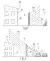
- One possible application of the invention is to reduce the quantity of sound present in a predetermined zone Z1, for example a worksite producing considerable amounts of noise, which is also located close to a sound-reflecting surface 21, such as a nearby building 23.
- a panel P according to the invention (especially the type of embodiment thereof illustrated in figures 2 or 2A) is placed between the worksite and the building, which panel P has the axes of the tubular cells 10 oriented so that the cells 10 are able to collect at least a majority of the sound waves R5 produced by the source 22 (for example, a pneumatic drill) and to send them (trajectory R5') in an upwards direction, above the zone Z1 so that the people working in the work-site are spared being struck full blast by the noise.
- the source 22 for example, a pneumatic drill
- the building 23 is also not struck by the issuing sound.
- a further possible application, illustrated in figure 6, is for acoustically isolating a first zone Z3, in which for example there are dwellings 31, from a second zone Z4, where a sound is generated, for example a busy street.
- a panel P according to the invention is placed (in particular a panel of the type illustrated in figure 2B), in which the axes of the tubular cells 10 are oriented such that the cells are able to gather at least the majority of the sound waves R6 coming from the second zone Z4 and send them (trajectory R6') upwards and above the first zone Z3.
- cells 10 having a curved corridor axis A, having an inclination and being almost horizontal at the entrance thereof, so as to capture all or nearly all of the sound waves coming from the street (as the waves will strike the panel at an angle B which is greater than the described limit angle B 0 ) and direct them , as they exit, upwards at an inclination which overshoots the zone comprising the dwellings 31.
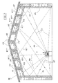
- a further possible application, illustrated in figure 7, is for reducing the noise in a large closed space, such as inside a workshop 40 tending to be noisy.
- the lateral walls of the workshop 40 are covered floor-to-ceiling with vertical panels P1 according to the invention (in particular of the type illustrated in figure 2 or 2A), while different panels P2 are used at ceiling height (which might also basically be of the type illustrated in figure 2 or 2A) which are shorter in height, parallel to one another and vertically projecting downwards starting from the roof covering 41, and defining a series of adjacent chambers 42.
- These chambers 42 extend over the whole length of the roof covering 41 and are inferiorly closed by other panels P3 which are horizontal or inclined parallel to the roof covering 41 (of the type illustrated in figure 2B).
- the axes of the cells 10 of the panels P2 set side-by-side are parallel to each other as well as to the roof covering 41.
- the axes of the cells 10 of the panels P1 are directed upwards so that when they are struck by the waves (trajectories R7) coming from a sound source S in the internal environment, the waves (trajectories R7') are reflected towards the panels P3.
- the panels P3 then direct the sound waves (trajectories R7") internally of the chambers 42 towards the panels P2; the panels P2 are directed one towards another and produce trajectories R7" which bounce from one panel P2 to another, are therefore damped and never exit from the chamber 42.
- the result of this is that a notable quantity of the sound produced in the closed environment is absorbed by the chambers 42.
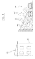
- a further possible application, illustrated in figure 8, is for acoustically isolating a first zone Z5, containing for example swellings, from a second zone Z6 in which a sound is generated, for example a busy street.
- a panel P according to the invention is placed between the two zones Z5 and
- the axes of the tubular cells 10 are oriented downwards so that the cells 10 can gather up the majority of the sound waves R9 coming from the second zone Z6.
- the waves exiting from the panel P are directed (trajectory R9') downwards (where the part which is not absorbed is reflected upwards - trajectories R9") and in any case away from the zone Z6, so that they do not strike the dwellings 51.
Landscapes
- Physics & Mathematics (AREA)
- Engineering & Computer Science (AREA)
- Architecture (AREA)
- Acoustics & Sound (AREA)
- Civil Engineering (AREA)
- Structural Engineering (AREA)
- Electromagnetism (AREA)
- Building Environments (AREA)
Applications Claiming Priority (2)
| Application Number | Priority Date | Filing Date | Title |
|---|---|---|---|
| ITMO20030353 | 2003-12-23 | ||
| ITMO20030353 ITMO20030353A1 (it) | 2003-12-23 | 2003-12-23 | Pannello fono-direzionale per condizionamento del suono. |
Publications (1)
| Publication Number | Publication Date |
|---|---|
| EP1548198A1 true EP1548198A1 (de) | 2005-06-29 |
Family
ID=34531932
Family Applications (1)
| Application Number | Title | Priority Date | Filing Date |
|---|---|---|---|
| EP04078315A Withdrawn EP1548198A1 (de) | 2003-12-23 | 2004-12-07 | Schallrichtungspaneel für Schallkonditionierung |
Country Status (2)
| Country | Link |
|---|---|
| EP (1) | EP1548198A1 (de) |
| IT (1) | ITMO20030353A1 (de) |
Cited By (3)
| Publication number | Priority date | Publication date | Assignee | Title |
|---|---|---|---|---|
| EP1845200A1 (de) | 2006-04-10 | 2007-10-17 | Offner Öko-Produkte GmbH | Lärmschutz-Element |
| DE102013000691A1 (de) * | 2013-01-15 | 2014-07-17 | Kai Klinder | Schallabsorbierender Hohlraum-Absorber mit engmaschiger Wabenstruktur zum Aufbau von Schallschutzeinrichtungen |
| EP2921602A1 (de) * | 2014-03-19 | 2015-09-23 | REHAU AG + Co | Vorrichtung zur beeinflussung von schall bzw. schallenergie |
Citations (7)
| Publication number | Priority date | Publication date | Assignee | Title |
|---|---|---|---|---|
| US3505030A (en) * | 1965-11-16 | 1970-04-07 | Du Pont | Composite articles of manufacture and apparatus for their use |
| US4069768A (en) * | 1975-05-28 | 1978-01-24 | Bridgestone Tire Company Limited | Device for controlling a propagation direction of noise |
| US4113053A (en) * | 1976-10-06 | 1978-09-12 | Bridgestone Tire Company Limited | Sound absorbing body |
| US4158401A (en) * | 1975-07-11 | 1979-06-19 | Bridgestone Tire Company Limited | Device for controlling a propagation direction of noise |
| DE3146674A1 (de) * | 1981-11-25 | 1983-07-28 | Beyer, Erwin, Dr.-Ing. e.h., 4000 Düsseldorf | Laermschutzkonstruktion |
| US5633066A (en) * | 1994-03-21 | 1997-05-27 | Corning Incorporated | Honeycomb structures having non-parallel cells and method of making |
| EP1217185A2 (de) * | 2000-12-20 | 2002-06-26 | Corning Incorporated | Diesel-Partikelfilter |
-
2003
- 2003-12-23 IT ITMO20030353 patent/ITMO20030353A1/it unknown
-
2004
- 2004-12-07 EP EP04078315A patent/EP1548198A1/de not_active Withdrawn
Patent Citations (7)
| Publication number | Priority date | Publication date | Assignee | Title |
|---|---|---|---|---|
| US3505030A (en) * | 1965-11-16 | 1970-04-07 | Du Pont | Composite articles of manufacture and apparatus for their use |
| US4069768A (en) * | 1975-05-28 | 1978-01-24 | Bridgestone Tire Company Limited | Device for controlling a propagation direction of noise |
| US4158401A (en) * | 1975-07-11 | 1979-06-19 | Bridgestone Tire Company Limited | Device for controlling a propagation direction of noise |
| US4113053A (en) * | 1976-10-06 | 1978-09-12 | Bridgestone Tire Company Limited | Sound absorbing body |
| DE3146674A1 (de) * | 1981-11-25 | 1983-07-28 | Beyer, Erwin, Dr.-Ing. e.h., 4000 Düsseldorf | Laermschutzkonstruktion |
| US5633066A (en) * | 1994-03-21 | 1997-05-27 | Corning Incorporated | Honeycomb structures having non-parallel cells and method of making |
| EP1217185A2 (de) * | 2000-12-20 | 2002-06-26 | Corning Incorporated | Diesel-Partikelfilter |
Cited By (3)
| Publication number | Priority date | Publication date | Assignee | Title |
|---|---|---|---|---|
| EP1845200A1 (de) | 2006-04-10 | 2007-10-17 | Offner Öko-Produkte GmbH | Lärmschutz-Element |
| DE102013000691A1 (de) * | 2013-01-15 | 2014-07-17 | Kai Klinder | Schallabsorbierender Hohlraum-Absorber mit engmaschiger Wabenstruktur zum Aufbau von Schallschutzeinrichtungen |
| EP2921602A1 (de) * | 2014-03-19 | 2015-09-23 | REHAU AG + Co | Vorrichtung zur beeinflussung von schall bzw. schallenergie |
Also Published As
| Publication number | Publication date |
|---|---|
| ITMO20030353A1 (it) | 2005-06-24 |
Similar Documents
| Publication | Publication Date | Title |
|---|---|---|
| US4071989A (en) | Sound insulative masonry block | |
| CN211597188U (zh) | 一种高降噪隔音房墙体结构 | |
| EP1548198A1 (de) | Schallrichtungspaneel für Schallkonditionierung | |
| US3997020A (en) | Sound absorber | |
| CN101012668B (zh) | 用于对容纳在封闭物内部的设备隔音的封闭物 | |
| KR20130062666A (ko) | 정밀 진동제어 발파공법 | |
| US7380636B2 (en) | Noise reducing equipment | |
| GB0307798D0 (en) | Impact absorbing structure | |
| US2657759A (en) | Acoustic block or tile | |
| JP3892659B2 (ja) | 床構造 | |
| KR101076381B1 (ko) | 층간 소음방지재 | |
| KR101637438B1 (ko) | 사격장 소음저감시설 | |
| JP7456753B2 (ja) | 吸音器、吸音器の調整方法、天井構造、及び建物 | |
| JP7402038B2 (ja) | 換気口端末部材、及び、建物 | |
| DE502005004929D1 (de) | Steinkorb zur Erstellung einer Schallschutzwand | |
| JPH11159043A (ja) | 床衝撃音低減構造 | |
| RU68009U1 (ru) | Панель шумопоглощающая | |
| KR200304472Y1 (ko) | 이동표적용 방음판 | |
| KR20020038153A (ko) | 환경친화적 방음벽의 방음재 | |
| KR102788460B1 (ko) | 천장 설치형 층간소음 저감장치와 이의 시공방법 | |
| JP2000008333A (ja) | 上方に放射される交通騒音の低減構造 | |
| RU2279032C2 (ru) | Пулеулавливающая антирикошетная облицовка | |
| KR102830375B1 (ko) | 공명 흡음형 가설 방음벽체 패널 | |
| CN218842908U (zh) | 一种组合式施工隔音组件 | |
| RU40637U1 (ru) | Устройство для защиты от акустических шумов жилых домов |
Legal Events
| Date | Code | Title | Description |
|---|---|---|---|
| PUAI | Public reference made under article 153(3) epc to a published international application that has entered the european phase |
Free format text: ORIGINAL CODE: 0009012 |
|
| AK | Designated contracting states |
Kind code of ref document: A1 Designated state(s): AT BE BG CH CY CZ DE DK EE ES FI FR GB GR HU IE IS IT LI LT LU MC NL PL PT RO SE SI SK TR |
|
| AX | Request for extension of the european patent |
Extension state: AL BA HR LV MK YU |
|
| 17P | Request for examination filed |
Effective date: 20051207 |
|
| AKX | Designation fees paid |
Designated state(s): AT BE BG CH CY CZ DE DK EE ES FI FR GB GR HU IE IS IT LI LT LU MC NL PL PT RO SE SI SK TR |
|
| 17Q | First examination report despatched |
Effective date: 20071127 |
|
| STAA | Information on the status of an ep patent application or granted ep patent |
Free format text: STATUS: THE APPLICATION IS DEEMED TO BE WITHDRAWN |
|
| 18D | Application deemed to be withdrawn |
Effective date: 20080408 |