EP1547958B1 - Thermischer Schutz für elektromagnetische Aktuatoren - Google Patents
Thermischer Schutz für elektromagnetische Aktuatoren Download PDFInfo
- Publication number
- EP1547958B1 EP1547958B1 EP20040029145 EP04029145A EP1547958B1 EP 1547958 B1 EP1547958 B1 EP 1547958B1 EP 20040029145 EP20040029145 EP 20040029145 EP 04029145 A EP04029145 A EP 04029145A EP 1547958 B1 EP1547958 B1 EP 1547958B1
- Authority
- EP
- European Patent Office
- Prior art keywords
- actuator
- temperature
- controller
- current
- elevator installation
- Prior art date
- Legal status (The legal status is an assumption and is not a legal conclusion. Google has not performed a legal analysis and makes no representation as to the accuracy of the status listed.)
- Expired - Lifetime
Links
- 238000011156 evaluation Methods 0.000 claims abstract description 18
- 238000009434 installation Methods 0.000 claims abstract description 16
- 238000000034 method Methods 0.000 claims abstract description 8
- 230000000712 assembly Effects 0.000 claims abstract description 6
- 238000000429 assembly Methods 0.000 claims abstract description 6
- 230000001133 acceleration Effects 0.000 claims description 13
- 230000010355 oscillation Effects 0.000 description 8
- 230000006866 deterioration Effects 0.000 description 6
- 238000004804 winding Methods 0.000 description 6
- 230000006378 damage Effects 0.000 description 5
- 230000004913 activation Effects 0.000 description 4
- 238000012546 transfer Methods 0.000 description 4
- 238000013016 damping Methods 0.000 description 3
- 230000001419 dependent effect Effects 0.000 description 3
- 230000000694 effects Effects 0.000 description 2
- 238000013021 overheating Methods 0.000 description 2
- 238000007796 conventional method Methods 0.000 description 1
- 238000005265 energy consumption Methods 0.000 description 1
- 230000004907 flux Effects 0.000 description 1
- 238000010438 heat treatment Methods 0.000 description 1
- 238000012545 processing Methods 0.000 description 1
- 238000005070 sampling Methods 0.000 description 1
- 230000003068 static effect Effects 0.000 description 1
- 230000001360 synchronised effect Effects 0.000 description 1
- 238000012360 testing method Methods 0.000 description 1
Images



Classifications
-
- B—PERFORMING OPERATIONS; TRANSPORTING
- B66—HOISTING; LIFTING; HAULING
- B66B—ELEVATORS; ESCALATORS OR MOVING WALKWAYS
- B66B7/00—Other common features of elevators
- B66B7/02—Guideways; Guides
- B66B7/04—Riding means, e.g. Shoes, Rollers, between car and guiding means, e.g. rails, ropes
- B66B7/041—Riding means, e.g. Shoes, Rollers, between car and guiding means, e.g. rails, ropes including active attenuation system for shocks, vibrations
- B66B7/044—Riding means, e.g. Shoes, Rollers, between car and guiding means, e.g. rails, ropes including active attenuation system for shocks, vibrations with magnetic or electromagnetic means
-
- B—PERFORMING OPERATIONS; TRANSPORTING
- B66—HOISTING; LIFTING; HAULING
- B66B—ELEVATORS; ESCALATORS OR MOVING WALKWAYS
- B66B5/00—Applications of checking, fault-correcting, or safety devices in elevators
- B66B5/0006—Monitoring devices or performance analysers
- B66B5/0037—Performance analysers
-
- B—PERFORMING OPERATIONS; TRANSPORTING
- B66—HOISTING; LIFTING; HAULING
- B66B—ELEVATORS; ESCALATORS OR MOVING WALKWAYS
- B66B7/00—Other common features of elevators
- B66B7/02—Guideways; Guides
- B66B7/04—Riding means, e.g. Shoes, Rollers, between car and guiding means, e.g. rails, ropes
- B66B7/046—Rollers
Definitions
- the present invention relates to a method and apparatus for preventing overheating of an electromagnetic actuator.
- EP-B-0731051 describes an elevator installation in which the ride quality is actively controlled using a plurality of electromagnetic linear actuators.
- Such a system in commonly referred to as an active ride control system.
- sensors mounted on the car measure the vibrations occurring transverse to the direction of travel. Signals from the sensors are input to a controller which computes the activation current required to suppress the sensed vibrations for each linear actuator.
- These activation currents are supplied to the linear actuators which actively dampen the vibrations and thereby the ride quality for passengers traveling within the car is enhanced.
- a conventional solution to this problem would be to incorporate a bimetallic strip into the actuator to control its energization. Accordingly when the temperature of the actuator rises to the predetermined activation temperature of the bimetallic strip, the bimetallic strip within the actuator would break the energization circuit and the respective actuator would be de-energized until its temperature falls to below the predetermined activation temperature of the bimetallic strip. It will be appreciated that at this switch off point there would be an instantaneous deterioration in the performance of the active ride control system since a force would no longer be generated by the effected actuator to stabilize the elevator car. Furthermore this deterioration in performance would be immediately perceptible to any passengers traveling in the elevator car and would therefore defeat the purpose of, and undermine user confidence in, the active ride control system.
- the objective of the present invention is to overcome the problems associated with the prior art electromagnetic actuators by providing an apparatus and method according to the appended claims.
- the present invention provides a thermal protection device for an electromagnetic actuator, comprising a temperature evaluation unit that determines an estimate temperature of the actuator from a signal proportional to a current supplied to the actuator, and a limiter that restricts the current supplied to the actuator if the actual temperature of the actuator exceeds a first predetermined temperature.
- the temperature evaluation unit can be located remote from the actuator in any circuit controlling the current delivered to the actuator.
- the current supplied to the actuator is restricted to a minimal level if the actual temperature of the actuator exceeds a second predetermined temperature.
- the minimal level can be determined such that energy dissipated in the actuator due to the current is equal to or less than heat lost from the actuator due to conduction and convection. Accordingly, the actuator can be continuously energized albeit with a limited driving current.
- the invention is particularly advantageous when applied to actuators used in elevator systems to dampen the vibration of an elevator car as it travels along guide rails in a hoistway.
- the current to the actuators is gradually limited as the temperature exceeds the first predetermined temperature, as opposed to being switched off completely. Hence, and deterioration in the ride quality is less perceptible to passengers.
- thermal protection device and method can be easily incorporated in a controller for the actuators without any additional hardware components.
- FIG. 1 is a schematic illustration of an elevator installation incorporating an active ride control system according to the EP-B-0731051 which further includes a thermal protection unit in accordance with the present invention.
- An elevator car 1 is guided by roller guide assemblies 5 along rails 15 mounted in a shaft (not shown).
- Car 1 is carried elastically in a car frame 3 for passive oscillation damping.
- the passive oscillation damping is performed by several rubber springs 4, which are designed to be relatively stiff in order to isolate sound or vibrations having a frequency higher the 50 Hz.
- the roller guide assemblies 5 are laterally mounted above and below car frame 3.
- Each assembly 5 includes a mounting bracket and three rollers 6 carried on levers 7 which are pivotally connected to the bracket. Two of the rollers 6 are arranged laterally to engage opposing sides of the guide rail 15. The levers 7 carrying these two lateral rollers 6 are interconnected by a linkage 9 to ensure synchronous movement. The remaining, middle roller 6 is arranged to engage with a distal end of the guide rail 15.
- Each of the levers 7 is biased by a contact pressure spring 8 towards the guide rail 15. This spring biasing of the levers 7, and thereby the respective rollers 6, is a conventional method of passively dampening vibrations.
- Each roller guide assembly 5 further includes two actuators 10 disposed to actively move the middle lever 7 in the y direction and the two interconnected, lateral levers 7 in the x direction, respectively.
- the signals derived from the positions sensors 11 and accelerometers 12 are fed into a controller and power unit 14 mounted on the car 1.
- the controller and power unit 14 processes these signals to produce a current I to operate the actuators 10 in directions such to oppose the sensed oscillations. Thereby, damping of the oscillations acting on frame 3 and car 1 is achieved. Oscillations are reduced to the extent that they are imperceptible to the elevator passenger.
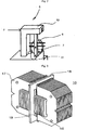
- FIG. 2 provides a further illustration of the arrangement of the middle roller 6 and lever 7 together with the associated actuator 10, it will be understood that the following description also applies to the two lateral rollers 6 and interconnected levers 7. Due to the parallel arrangement of the contact pressure spring 8 and the actuator 10 to the lever 7, the roller guide assembly 5 remains capable of operating even after a partial or complete failure of the active ride control system because the contact pressure spring 8 urges roller 6 against the guide rail 15 independently of the actuator 10. Hence, even when no current I is supplied to the actuator 10, the car frame 3 is passively dampened by the contact pressure springs 8.
- the actuator 10 is based on the principle of a moving magnet and comprises a laminated stator 17, windings 16 and a moving actuator part 18 comprising a permanent magnet 19.
- the moving actuator part 18 in connected to the top of the lever 7 so that as the current I supplied to the windings 16 changes, the magnetic flux changes thus causing the moving actuator part 18, lever 7 and coupled roller 6 towards or away from the guide rail 15.
- the actuator 10 has the advantage of simple controllability, low weight and small moving masses, and great dynamic and static force (e.g. 800N) for relatively low energy consumption.
- the objective of the present invention is to ensure maximum availability of the active ride control system but at the same time preventing thermal destruction of the actuators 10, particularly when a large asymmetric load is applied to the car 1 or where the car 1 is poorly balanced. In such circumstances it would be necessary for one or more of the actuators 10 to be powered continuously to overcome the imbalance. This continual energization would cause the actuator 10 to heat up and if left unchecked could potentially lead to the thermal destruction of the actuator 10 itself.
- the first step to achieving the objective is to assess the thermal characteristics of the actuators 10. From first principles, the power dissipated as heat by the electrical circuit (i.e. the windings 16) produces an increase in the temperature of the actuator 10. This can be expressed generally as: Power dissipated - > Temperature increase in actuator - effects of heat conduction & convention
- T n I 2 ⁇ R ⁇ ⁇ ⁇ t + c ⁇ M ⁇ T n - 1 - T amb ⁇ ⁇ ⁇ t ⁇ ⁇ ⁇ A 1 + h c ⁇ A 2 c ⁇ M - ⁇ ⁇ t ⁇ ⁇ ⁇ A 1 + h c ⁇ A 2
- the values for c, M, ⁇ , A 1 , h c and A 2 can easily be determined from experimentation in a climate test chamber. Furthermore, the resistance R of the windings 16 can be set to an average constant value, or for more accurate results the true temperature dependent function for the resistance R can be evaluated and used.
- FIG. 6 shows a signal flow scheme of the active ride control system for the elevator installation of FIG. 1 incorporating thermal protection according to the invention.
- External disturbances act of the car 1 and frame 3 as they travel along the guide rails 15. These external disturbances generally comprise high frequency vibrations due mainly to the unevenness of the guide rails 15 and relatively low frequency forces 27 produced by asymmetrical loading of the car 1, lateral forces from the traction cable and air disturbance or wind forces.
- the disturbances are sensed by the positions sensors 11 and accelerometers 12 which produce signals that are fed into the controller and power unit 14.
- the sensed acceleration signal is inverted at the summation point 21 and fed into an acceleration controller 23 as an acceleration error signal e a .
- the acceleration controller 23 determines the current I a required by the actuator 10 in order to counteract the vibrations causing the sensed acceleration.
- the sensed position signal is compared with a reference value P ref at summation point 20 to produce a position error signal e p .
- the position error signal e p is then fed into a position controller 22 which determines the current I p required by the actuator 10 in order to counteract the disturbances causing the sensed position signal to deviate from the reference value P ref .
- the two derived currents I a and I p are simply combined at a summation point 26 and then delivered as a combined current I to the actuator 10.
- the current I p from the position controller 22 is further processed by a limiter 25 producing a current I plim which is passed to the summation point 26 for combination with the current I a from the acceleration controller 23 to provide a combined current I to the actuator 10.
- the current value I plim from the limiter 25 is also used as an input to a temperature evaluation unit 24 incorporating a transfer function corresponding to EQN. 3. Since the resistance R of the windings 16 is either a constant or represented as a temperature dependent function and the sampling period ⁇ t can be set to that of the controller 14, the only variables (inputs) required by the transfer function are current I plim , which as explained above is derived from the limiter 25, the ambient temperature T amb , which can either be a preset constant or measured using a temperature sensor, and the previously recorded value for the actuator temperature T n-1 , which is stored in a register 24a in the temperature evaluation unit 24. Accordingly, the actual actuator temperature T n is determined by the temperature evaluation unit 24 and input to the limiter 25.
- the limiter 25 determines a maximum permissible current value I pmax deliverable to the actuator 10 for a given actuator temperature T n such as not to cause thermal deterioration of the actuator 10. As shown in FIG. 4, the maximum permissible current value I pmax is constant for all temperatures up to a lower threshold actuator temperature T nL . This constant current value is purely dependent on the power electronics driving the position controller 22. As the temperature of the actuator 10 exceeds the lower threshold T nL , the limiter 25 restricts the maximum permissible current value I pmax . If the temperature of the actuator 10 reaches an upper threshold T nH , no current is derived from the limiter 25. Hence, the actuator 10 is protected from thermal deterioration and destruction.
- the limiter 25 and temperature evaluation unit 24 are applied to the current I p output from the position controller 22 only.
- the reason for this is that it is the low frequency disturbances 27, such as asymmetric loading of the car 1, which require the continuous energization of the actuator 10 and thereby cause the greatest heating effect on the actuator 10.
- These low frequency disturbances 27 manifest themselves primarily in the position error signal e p .
- an additional limiter 25 and temperature evaluation unit 24 can be installed on the output of the acceleration controller 23.
- a single current limiter 25 and temperature evaluation unit 24 can be applied to the output from summation point 26 to limit the combined current I.
- temperature evaluation unit 24 and current limiter 25 can be combined as a single unit in the controller.
- FIG. 7 A presently preferred embodiment of the invention is illustrated in FIG. 7.
- the combined analogue controller and power unit 14 from FIG. 4 have been separated into a discrete digital controller 30 and a discrete actuator power unit 31.
- This enables the digital processing of signals within the controller 30 which greatly improves efficiency and accuracy.
- All components of the controller 30 correspond to those in FIG. 6, however it will be understood that the digital signals from the position controller 22, acceleration controller 23, the limiter 25 and the summation point 26 referred to as force command signals F in the drawing are proportional to the currents I in the previous embodiment. It is only after the combined force command signal F from the summation point 26 in the controller 30 is passed to the power unit 31 that the actual driving current I is supplied to the actuator 10.
- the limiter 25 and temperature evaluation unit 24 monitor and limit the combined force command signal (F) derived from the summation of the position force command signal (F p ) and the acceleration force command (F a ) at the summation point 26.
- guide assemblies 5 may incorporate guide shoes rather then rollers 6 to guide the car 1 along the guide rails 15.
Landscapes
- Physics & Mathematics (AREA)
- Electromagnetism (AREA)
- Cage And Drive Apparatuses For Elevators (AREA)
- Lift-Guide Devices, And Elevator Ropes And Cables (AREA)
Claims (11)
- Aufzugsanlage, umfassend:eine Aufzugskabine (1), die von Führungsbaugruppen (5) entlang Führungsschienen (15) geführt wird, die in einem Schacht montiert sind;mindestens einen elektromagnetischen Aktuator (10), der zwischen der Kabine (1) und jeder Führungsbaugruppe (5) montiert ist; undeinen Controller (14; 30), der als Reaktion auf erfaßte Schwingungen eine Bestromung der Aktuatoren (10) steuert,dadurch gekennzeichnet, daß sie weiterhin folgendes umfaßt: eine Temperaturauswerteeinheit (24), die eine Temperatur (Tn) des Aktuators (10) entfernt bestimmt; undeinen Begrenzer (25), der einen dem Aktuator (10) zugeführten Strom (I) beschränkt, wenn die bestimmte Temperatur (Tn) des Aktuators (10) eine erste vorbestimmte Temperatur (TnL) übersteigt.
- Aufzugsanlage nach Anspruch 1, wobei die Temperaturauswerteeinheit (24) ein Register (24a) enthält, das mindestens einen zuvor aufgezeichneten Wert für die Aktuatortemperatur (Tn-1) speichert.
- Aufzugsanlage nach Anspruch 1 oder 2, wobei die Temperaturauswerteeinheit (24) und der Begrenzer (25) in den Controller (14; 30) integriert sind.
- Aufzugsanlage nach Anspruch 3, wobei der Controller (14; 30) einen auf erfaßte Positionssignale reagierenden Positionscontroller (22) und einen auf erfaßte Beschleunigungen reagierenden Beschleunigungscontroller (23) enthält und wobei die Ausgabe (Ip; Fp) von dem Positionscontroller (22) mit der Ausgabe (Ia; Fa) von dem Beschleunigungscontroller (23) an einem Summierungspunkt (26) verknüpft wird, um ein Signal (I; Flim) proportional zu dem dem Aktuator (10) gelieferten Strom (I) zu erzeugen.
- Aufzugsanlage nach Anspruch 4, wobei der Controller (14) ein analoger Controller ist und die Ausgabe von dem Summierungspunkt (26) der dem Aktuator (10) zugeführte Strom (I) ist.
- Aufzugsanlage nach Anspruch 4, wobei der Controller (30) ein digitaler Controller ist und die Ausgabe von dem Summierungspunkt (26) ein Kraftbefehlssignal (Flim) ist, das einer Leistungseinheit (31) zugeführt wird, die danach den dem Aktuator (10) gelieferten Strom (I) liefert.
- Aufzugsanlage nach einem der Ansprüche 4 bis 6, wobei die Temperaturauswerteeinheit (24) und der Begrenzer (25) zwischen dem Positionscontroller (22) und dem Summierungspunkt (26) installiert sind und die Temperaturauswerteeinheit (24) die Temperatur (Tn) auf der Basis eines vom Begrenzer (25) ausgegebenen Signals bestimmt.
- Aufzugsanlage nach einem der Ansprüche 4 bis 6, wobei die Temperaturauswerteeinheit (24) und der Begrenzer (25) zwischen dem Summierungspunkt (26) und dem Aktuator (10) installiert sind und die Temperaturauswerteeinheit (24) die Temperatur (Tn) auf der Basis eines vom Begrenzer (25) ausgegebenen Signals bestimmt.
- Verfahren zum thermischen Schützen eines zwischen der Kabine (1) und einer Führungsbaugruppe (5) einer Aufzugsanlage montierten elektromagnetischen Aktuators (10) zum Unterdrücken erfaßter Schwingungen, umfassend die folgenden Schritte:a) entferntes Bestimmen einer Temperatur (Tn) des Aktuators (10) undb) Einschränken des dann dem Aktuator (10) gelieferten Stroms (I), wenn die bestimmte Temperatur (Tn) des Aktuators (10) eine vorbestimmte Temperatur (TnL) übersteigt.
- Verfahren nach Anspruch 9, weiterhin umfassend den Schritt des Einschränkens des dem Aktuator (10) gelieferten Stroms (I) auf einen Minimalpegel, wenn die Ist-Temperatur (Tn) des Aktuators (10) eine zweite vorbestimmte Temperatur (TnH) übersteigt.
- Verfahren nach Anspruch 10, wobei der Minimalpegel derart bestimmt wird, daß im Aktuator (10) aufgrund des Stroms (Iplim) abgeführte Energie kleiner oder gleich von dem Aktuator (10) aufgrund von Leitung und Konvektion verlorengegangener Wärme ist.
Priority Applications (1)
| Application Number | Priority Date | Filing Date | Title |
|---|---|---|---|
| EP20040029145 EP1547958B1 (de) | 2003-12-22 | 2004-12-09 | Thermischer Schutz für elektromagnetische Aktuatoren |
Applications Claiming Priority (3)
| Application Number | Priority Date | Filing Date | Title |
|---|---|---|---|
| EP03405916 | 2003-12-22 | ||
| EP03405916 | 2003-12-22 | ||
| EP20040029145 EP1547958B1 (de) | 2003-12-22 | 2004-12-09 | Thermischer Schutz für elektromagnetische Aktuatoren |
Publications (2)
| Publication Number | Publication Date |
|---|---|
| EP1547958A1 EP1547958A1 (de) | 2005-06-29 |
| EP1547958B1 true EP1547958B1 (de) | 2007-05-23 |
Family
ID=34553667
Family Applications (1)
| Application Number | Title | Priority Date | Filing Date |
|---|---|---|---|
| EP20040029145 Expired - Lifetime EP1547958B1 (de) | 2003-12-22 | 2004-12-09 | Thermischer Schutz für elektromagnetische Aktuatoren |
Country Status (1)
| Country | Link |
|---|---|
| EP (1) | EP1547958B1 (de) |
Families Citing this family (3)
| Publication number | Priority date | Publication date | Assignee | Title |
|---|---|---|---|---|
| FI120070B (fi) * | 2007-10-01 | 2009-06-15 | Kone Corp | Sähkökäytön annon rajoittaminen sekä hissin suojaus |
| WO2019222169A1 (en) * | 2018-05-15 | 2019-11-21 | Clearmotion Acquisition I Llc | Active seat suspension failsafe operation |
| US11603288B2 (en) * | 2020-06-29 | 2023-03-14 | Otis Elevator Company | Magnet assemblies of electromechanical actuators for elevator systems |
Family Cites Families (2)
| Publication number | Priority date | Publication date | Assignee | Title |
|---|---|---|---|---|
| ATE201380T1 (de) * | 1995-03-10 | 2001-06-15 | Inventio Ag | Einrichtung und verfahren zur schwingungsdämpfung an einer aufzugskabine |
| JP2002356287A (ja) * | 2001-05-31 | 2002-12-10 | Mitsubishi Electric Corp | エレベータの制振装置 |
-
2004
- 2004-12-09 EP EP20040029145 patent/EP1547958B1/de not_active Expired - Lifetime
Also Published As
| Publication number | Publication date |
|---|---|
| EP1547958A1 (de) | 2005-06-29 |
Similar Documents
| Publication | Publication Date | Title |
|---|---|---|
| US9114954B2 (en) | Active guiding and balance system for an elevator | |
| US5086882A (en) | Elevator apparatus provided with guiding device used for preventing passenger cage vibration | |
| JP5009304B2 (ja) | エレベータ装置 | |
| KR20130006708A (ko) | 엘리베이터 시스템 내 카의 횡방향 움직임 감소 시스템 및 방법 | |
| US7493990B2 (en) | Thermal protection of electromagnetic actuators | |
| KR101139736B1 (ko) | 승강기 승강실의 능동적인 진동 감쇠를 위한 제어기 관리 | |
| GB2313928A (en) | Elevator speed control | |
| JP5166673B2 (ja) | エレベータケージの振動減衰装置 | |
| JP2008168980A (ja) | エレベータ乗りかごの縦振動抑制装置 | |
| CN110155852B (zh) | 主动减振装置 | |
| EP1547958A1 (de) | Thermischer Schutz für elektromagnetische Aktuatoren | |
| US7314118B2 (en) | Equipment and method for vibration damping of a lift cage | |
| HK1079173B (en) | Thermal protection of electromagnetic actuators | |
| EP1547955B1 (de) | Steuerungseinheit für die aktive Schwingungsdämpfung der Vibrationen einer Aufzugskabine | |
| HK1079181B (en) | Controller supervision for active vibration damping of elevator cars |
Legal Events
| Date | Code | Title | Description |
|---|---|---|---|
| PUAI | Public reference made under article 153(3) epc to a published international application that has entered the european phase |
Free format text: ORIGINAL CODE: 0009012 |
|
| AK | Designated contracting states |
Kind code of ref document: A1 Designated state(s): AT BE BG CH CY CZ DE DK EE ES FI FR GB GR HU IE IS IT LI LT LU MC NL PL PT RO SE SI SK TR |
|
| AX | Request for extension of the european patent |
Extension state: AL BA HR LV MK YU |
|
| 17P | Request for examination filed |
Effective date: 20051208 |
|
| AKX | Designation fees paid |
Designated state(s): AT CH DE FR GB LI |
|
| REG | Reference to a national code |
Ref country code: HK Ref legal event code: DE Ref document number: 1079173 Country of ref document: HK |
|
| GRAP | Despatch of communication of intention to grant a patent |
Free format text: ORIGINAL CODE: EPIDOSNIGR1 |
|
| GRAS | Grant fee paid |
Free format text: ORIGINAL CODE: EPIDOSNIGR3 |
|
| GRAA | (expected) grant |
Free format text: ORIGINAL CODE: 0009210 |
|
| AK | Designated contracting states |
Kind code of ref document: B1 Designated state(s): AT CH DE FR GB LI |
|
| REG | Reference to a national code |
Ref country code: GB Ref legal event code: FG4D Free format text: NOT ENGLISH |
|
| REG | Reference to a national code |
Ref country code: CH Ref legal event code: EP |
|
| REF | Corresponds to: |
Ref document number: 502004003872 Country of ref document: DE Date of ref document: 20070705 Kind code of ref document: P |
|
| ET | Fr: translation filed | ||
| REG | Reference to a national code |
Ref country code: HK Ref legal event code: GR Ref document number: 1079173 Country of ref document: HK |
|
| PLBE | No opposition filed within time limit |
Free format text: ORIGINAL CODE: 0009261 |
|
| STAA | Information on the status of an ep patent application or granted ep patent |
Free format text: STATUS: NO OPPOSITION FILED WITHIN TIME LIMIT |
|
| 26N | No opposition filed |
Effective date: 20080226 |
|
| PGFP | Annual fee paid to national office [announced via postgrant information from national office to epo] |
Ref country code: AT Payment date: 20101214 Year of fee payment: 7 Ref country code: FR Payment date: 20110104 Year of fee payment: 7 |
|
| PGFP | Annual fee paid to national office [announced via postgrant information from national office to epo] |
Ref country code: GB Payment date: 20101221 Year of fee payment: 7 |
|
| PGFP | Annual fee paid to national office [announced via postgrant information from national office to epo] |
Ref country code: DE Payment date: 20101222 Year of fee payment: 7 Ref country code: CH Payment date: 20110318 Year of fee payment: 7 |
|
| REG | Reference to a national code |
Ref country code: CH Ref legal event code: PL |
|
| GBPC | Gb: european patent ceased through non-payment of renewal fee |
Effective date: 20111209 |
|
| REG | Reference to a national code |
Ref country code: FR Ref legal event code: ST Effective date: 20120831 |
|
| REG | Reference to a national code |
Ref country code: DE Ref legal event code: R119 Ref document number: 502004003872 Country of ref document: DE Effective date: 20120703 |
|
| PG25 | Lapsed in a contracting state [announced via postgrant information from national office to epo] |
Ref country code: CH Free format text: LAPSE BECAUSE OF NON-PAYMENT OF DUE FEES Effective date: 20111231 Ref country code: GB Free format text: LAPSE BECAUSE OF NON-PAYMENT OF DUE FEES Effective date: 20111209 Ref country code: LI Free format text: LAPSE BECAUSE OF NON-PAYMENT OF DUE FEES Effective date: 20111231 Ref country code: DE Free format text: LAPSE BECAUSE OF NON-PAYMENT OF DUE FEES Effective date: 20120703 |
|
| REG | Reference to a national code |
Ref country code: AT Ref legal event code: MM01 Ref document number: 362892 Country of ref document: AT Kind code of ref document: T Effective date: 20111209 |
|
| PG25 | Lapsed in a contracting state [announced via postgrant information from national office to epo] |
Ref country code: AT Free format text: LAPSE BECAUSE OF NON-PAYMENT OF DUE FEES Effective date: 20111209 |
|
| PG25 | Lapsed in a contracting state [announced via postgrant information from national office to epo] |
Ref country code: FR Free format text: LAPSE BECAUSE OF NON-PAYMENT OF DUE FEES Effective date: 20120102 |