EP1547957A1 - Einrichtung zur Schwingungsdämpfung an einer Aufzugskabine - Google Patents
Einrichtung zur Schwingungsdämpfung an einer Aufzugskabine Download PDFInfo
- Publication number
- EP1547957A1 EP1547957A1 EP04029144A EP04029144A EP1547957A1 EP 1547957 A1 EP1547957 A1 EP 1547957A1 EP 04029144 A EP04029144 A EP 04029144A EP 04029144 A EP04029144 A EP 04029144A EP 1547957 A1 EP1547957 A1 EP 1547957A1
- Authority
- EP
- European Patent Office
- Prior art keywords
- control device
- controller
- elevator car
- acceleration
- car
- Prior art date
- Legal status (The legal status is an assumption and is not a legal conclusion. Google has not performed a legal analysis and makes no representation as to the accuracy of the status listed.)
- Withdrawn
Links
- 238000013016 damping Methods 0.000 title description 7
- 230000001133 acceleration Effects 0.000 claims abstract description 38
- 230000003321 amplification Effects 0.000 claims abstract description 10
- 238000003199 nucleic acid amplification method Methods 0.000 claims abstract description 10
- 230000001419 dependent effect Effects 0.000 claims description 8
- 230000008859 change Effects 0.000 claims description 4
- 230000007423 decrease Effects 0.000 claims description 4
- 230000004048 modification Effects 0.000 claims description 3
- 238000012986 modification Methods 0.000 claims description 3
- 230000004913 activation Effects 0.000 claims 5
- 230000003111 delayed effect Effects 0.000 claims 1
- 239000000725 suspension Substances 0.000 claims 1
- 230000009467 reduction Effects 0.000 abstract description 3
- 230000010355 oscillation Effects 0.000 abstract description 2
- 230000003213 activating effect Effects 0.000 abstract 1
- 238000000034 method Methods 0.000 description 11
- 108010066057 cabin-1 Proteins 0.000 description 5
- 230000008569 process Effects 0.000 description 5
- 238000010586 diagram Methods 0.000 description 4
- 238000013461 design Methods 0.000 description 3
- 230000008901 benefit Effects 0.000 description 2
- 238000006243 chemical reaction Methods 0.000 description 2
- 238000012937 correction Methods 0.000 description 2
- 238000006073 displacement reaction Methods 0.000 description 2
- 230000035939 shock Effects 0.000 description 2
- 230000001629 suppression Effects 0.000 description 2
- 238000004458 analytical method Methods 0.000 description 1
- 230000008094 contradictory effect Effects 0.000 description 1
- 230000009849 deactivation Effects 0.000 description 1
- 230000000694 effects Effects 0.000 description 1
- 238000011156 evaluation Methods 0.000 description 1
- 238000002955 isolation Methods 0.000 description 1
- 238000012423 maintenance Methods 0.000 description 1
- 230000001105 regulatory effect Effects 0.000 description 1
- 230000003014 reinforcing effect Effects 0.000 description 1
- 230000007704 transition Effects 0.000 description 1
Images

Classifications
-
- B—PERFORMING OPERATIONS; TRANSPORTING
- B66—HOISTING; LIFTING; HAULING
- B66B—ELEVATORS; ESCALATORS OR MOVING WALKWAYS
- B66B7/00—Other common features of elevators
- B66B7/02—Guideways; Guides
- B66B7/04—Riding means, e.g. Shoes, Rollers, between car and guiding means, e.g. rails, ropes
- B66B7/041—Riding means, e.g. Shoes, Rollers, between car and guiding means, e.g. rails, ropes including active attenuation system for shocks, vibrations
-
- B—PERFORMING OPERATIONS; TRANSPORTING
- B66—HOISTING; LIFTING; HAULING
- B66B—ELEVATORS; ESCALATORS OR MOVING WALKWAYS
- B66B7/00—Other common features of elevators
- B66B7/02—Guideways; Guides
- B66B7/023—Mounting means therefor
- B66B7/027—Mounting means therefor for mounting auxiliary devices
-
- B—PERFORMING OPERATIONS; TRANSPORTING
- B66—HOISTING; LIFTING; HAULING
- B66B—ELEVATORS; ESCALATORS OR MOVING WALKWAYS
- B66B7/00—Other common features of elevators
- B66B7/02—Guideways; Guides
- B66B7/04—Riding means, e.g. Shoes, Rollers, between car and guiding means, e.g. rails, ropes
- B66B7/046—Rollers
Definitions
- the present invention relates to a device for reduction or damping oscillations of a guided on rails elevator car and a corresponding method for vibration damping.
- While driving an elevator car in a lift shaft can different forces on the out of the cabin body and one the cabin body occupying cabin frame existing cabin and the system to Stimulate vibrations.
- Cause of the vibrations can in particular Bumps in the guide rails and caused by the wind Be forces.
- lateral pulling forces can also be caused by the pull ropes or sudden changes in the position of the load during the journey Cause transverse vibrations.
- Object of the present invention is accordingly, a possibility specify vibrations or even shocks of the elevator car when starting and Stopping the elevator and to avoid loading and unloading the cabin.
- the object is achieved by a device for reducing vibrations of one Rail guided elevator car or by methods according to the independent Claims solved.
- the core idea of the present invention is to increase the gain for the Vibration suppression responsible control device speed and / or time-variable design. It is in a first aspect of the present invention, the gain of the control device dependent from the vertical speed of the elevator car, whereby on the Non-linear processes when starting and braking the elevator car can be better reacted. According to a second aspect of the present Invention is provided, the gain after switching on the To raise control device continuously or after switching off to lower continuously.
- the measures according to the invention allow the behavior of the principle linear and time-invariably designed control device to the above-mentioned nonlinear Adjust operations.
- relatively easy Measures to be taken when starting and stopping the elevator when Loading and unloading of the cabin and when switching on and off the control device occurring vibrations or even shocks due to an inappropriate reaction of a linear controller due to non-linear system changes, be suppressed.
- the speed or time-variable behavior of the control device realized in that the controller supplied error signals or Control deviations and / or the control signals generated by the controller for the Actuators weighted with time- or speed-dependent parameters become.
- the control device several reinforcing blocks be provided, with their output signals, the error or the control signals be weighted. Part of these blocks is used for the realization of the speed-dependent behavior of the control device, while, on the other hand, so-called time delay blocks for the reaction to the on and off Turning off the control device are responsible.
- This solution draws is characterized by the fact that it is relatively easy to implement. Especially it is not necessary to look at the actual regulator that supplied it Converts error signals into actuating signals for the actuators to exert influence. It So, as before, a linear and time invariant controller can be used.
- the control device on two internal controller, namely a Position controller and an acceleration controller.
- the position controller is therefor responsible, the adjustment of the guide elements in relation to the Guide rails so that at any time a sufficiently high damping path is available.
- the task of On the other hand the acceleration controller is the one occurring on the cabin frame Vibrations that can be caused by the bumps, too suppress.
- the setpoints of forces, both regulators of the actuators then are added accordingly and the actuators as one supplied common control signal.
- the two separate controller When using the two separate controller is preferably provided that after switching on the control device, first the gain of Positioner is linearly raised, while the Acceleration controller only with a certain time delay - also with a linear increase - is activated. After switching off the control device on the other hand, first the gain of the acceleration controller is linearly zero lowered and only with a certain time delay, the Position controller switched off.
- the car shown in Figure 1 and generally provided with the reference numeral 1 is divided into a cabin body 2 and a car frame 3.
- a cabin body 2 is mounted in the frame 3 by means of several rubber springs 4, which are intended for the isolation of structure-borne noise.
- These rubber springs 4 are relatively stiff designed to the occurrence of low-frequency vibrations to suppress.
- the car 1 is by means of four roller guides 5 at the two Guide rails 15 which are in a (not shown) elevator shaft are arranged.
- the four roller guides 5 are usually identical constructed and mounted laterally below and above the cab frame 3. she each have a stand, mounted on the three guide rollers 6 are, two lateral and one middle role.
- the guide rollers 6 are each movably supported by means of a lever 7 and are on a spring 8 on the Guide rails 15 pressed.
- the lever 7 of the two lateral guide rollers 6 are further connected via a pull rod 9, so that they themselves move in sync with each other.
- Per roller guide 5 two electric actuators 10 are provided, each exert a force on the lever 7, which acts parallel to the associated springs 8.
- a first actuator 10 moves the central lever 7 with the associated middle guide roller 6, whereas the second actuator 10, the two lateral lever 7 moves with the associated lateral guide rollers 6. about the actuators 10 thus the position of the lever 7 and the rollers 6 and thus the position of the elevator car 1 with respect to the guide rails 15 influenced.
- the various shifts or rotations in the five degrees of freedom are each on a different storage of the elevator car 1 to the four roller guides 5 due in the X and / or Y direction.
- two position sensors 11 are initially per roller guide 5 provided, a first sensor for detecting the position of the central lever 7 with the associated guide roller 6 and a second sensor for detecting the position of two lateral lever 7 with the associated lateral guide rollers.
- each roller guide 5 with two horizontally aligned Acceleration sensors 12 equipped, one of which accelerations in Displacement direction of the middle guide roller 6 and the second Accelerations perpendicular to it in the direction of displacement of the two lateral Guide rollers 6 detected.
- the measuring signals of the sensors 11 and 12 provide information about the current position of the elevator car 1 with respect to the two Guide rails 15 and also inform about whether the cabin body 1 current accelerations, which can lead to vibrations.
- a mounted on the ceiling of the cabin body 2 control unit 14 processes the from the sensors 11 and 12 transmitted signals and controls the evaluation of the Sensor signals by means of a power section, the electric actuators 10 of the four Roller guides 5 to the accelerations and vibrations in a suitable Counteract way.
- elevator car is a special feature in that on a roller guide 5 (here in the upper right roller guide) a Rotary motion sensor 13 is provided, the angle of rotation of him associated guide roller 6 measures.
- the about this rotary motion sensor 13th The measured values obtained provide information about the travel path of the car as well as about their current driving speed in vertical, ie in the Z direction. This will the speed-variable control described below according to the allows the present invention.
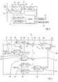
- FIGS. 2 and 3 show the signal flow diagram of the system according to the invention for active vibration damping.
- the basic structure according to FIG. 2 corresponds to the method, as used in EP 0 731 051 B1 comes.
- the signals shown are to be understood as vector signals, which include several signals of the same kind.
- the control device is as so-called MIMO (multi-input multi-output) controller designed on the basis of several Input signals several actuating signals for those located on the roller guides Actuators determined.
- MIMO multi-input multi-output
- the controller 19 is composed, as already mentioned, of two controllers, a position controller (K p ) 20 and an acceleration controller (K a ) 21.
- the reason for using two separate controllers is that a target of the controller 19 is cabin vibrations in the high frequency range (between 0.9 and 15 Hz, and preferably between 0.9 and 5 Hz) without the controlled elevator outside this frequency range behaving worse than the unregulated.
- the control device 19 must ensure that the setting of the cabin frame 3 with respect to the guide rails 15 is controlled so that at any time a sufficient Dämpfungsweg is available to the rollers. This is particularly important when the car 1 is loaded asymmetrically.
- the position controller 20 takes into account only the measured values the position sensors 11 and is accordingly for the maintenance of the Leading games of the cabin 1 responsible.
- the acceleration controller 21 processes the measured values of the acceleration sensors 12 and is responsible for the Suppression of vibrations required.
- the setpoints or set values of both Regulator 20 and 21 are added in the summation block 22 and as a common actuating signal supplied to the actuators 10.
- the solution to avoiding the above-mentioned conflict between the two Regulators 20 and 21 is based on the circumstance that for an imbalance of Cabin 1 responsible forces (a non-symmetrical loading of the cabin, a large lateral cable force and the like) change much more slowly than the other sources of interference that cause the cabin vibrations. in this connection These are mainly rail unevenness or air disturbances.
- the Amplification changes in the frequency domain are always continuous, that is: there are no fixed limits. At a certain frequency both controllers have 20 and 21 the same amount of influence.
- the acceleration controller 21 acts stronger, underneath, the position regulator 20 acts more strongly.
- control device 19 By the subdivision of the control device 19 in a position control loop as well An acceleration control loop can thus both be mentioned above To be tracked. Another advantage of the subdivision is further in that the controllers 20 and 21 contain no non-linearities. Otherwise, would be a stability analysis and thus a corresponding configuration of the two Controller difficult.
- FIG. 3 shows the extended signal flow diagram of the invention Method, wherein only the extended controller 19 is shown, since the others Parts of the system - cab, actuators and sensors - remain unchanged.
- the time and speed variable embodiment of the control device according to the invention is achieved by first weighting or multiplying the error signals e p supplied by the summation point 17 for the position controller 20 with certain factors before they are fed to the position controller 20.
- the variable behavior of the acceleration control loop is realized by weighting the control signals determined by the acceleration controller 21 on the basis of the error signals e a supplied to it with a plurality of amplification factors. In both cases, this ultimately varies the gain of the controller 20 and 21, respectively, with respect to the timing and the vertical speed of the car.
- the time-variable behavior of the two controllers 20 and 21 is effected by two so-called.
- the gain factor k Pt for the position controller 20 is first ramped up continuously with a linear increase from 0 to 1.
- the gain factor k at for the acceleration controller 21, on the other hand, follows with a certain time delay likewise with a linear increase of 0 1.
- the gain k at for the acceleration controller 21 is linearly reduced from 1 to 0, while on the other hand the gain k Pt for the position controller 20 is lowered in a time-delayed manner.
- the amplification factors k Pt and k at provided by the time delay blocks 23 and 24 are also multiplied in each case by a speed-dependent factor k Pv and k av in the blocks 27 and 28, so that the gain factors k Pvt for the position controller 20 or k avt for the acceleration controller 21.
- the speed factors k Pv and k av are generated by two blocks 25 and 26, which determine the two weighting factors in dependence on the speed value v determined by the rotary motion sensor 13, wherein the speed-dependent gain values are stored in tables and are linearly interpolated. It is important that the two gain factors k Pv and k av , which depend on the absolute magnitude of the speed v, never become zero themselves, which ensures that control is still carried out even when the car is stationary.
- the amplification factor k avt for the acceleration controller 21 formed in the manner just described is then multiplied in block 29 by the output or setting signal of the acceleration sensor 21.
- the amplification factor k Pvt for the position controller 20 is multiplied in the multiplication block 38 with a modified error signal e Plq and fed to the position controller 20.
- the error signal e P delivered by the summation block 17 itself is once again subject to a modification which takes account of the fact that a quick correction must be available given relatively large deviations in the position, such as may occur during standstill of the car (for example during loading).
- the square of the position error e P is formed with the same sign in block 30, so that on the one hand, the position error e P is present in linear and the other in a square shape.
- the squared error signal should be used to achieve a sufficiently fast position correction.
- the large gain would cause vibrations and even instabilities, so it is necessary to switch from the square position error to the linear position error depending on the vehicle speed.
- Block 31 first switches an output signal from 0 to 1 when the (direction-independent) travel speed v exceeds a threshold value v sw .
- Block 32 is a low-pass filter and causes a time-delayed continuous change of the output signal in the event of a sudden change in the input signal obtained from block 31.
- the output of the low-pass filter is multiplied by the linear position error in block 35, while in the summation block 34 a difference between the reference value 1 and the output value provided by the low-pass filter 32 is generated.
- the sum of the amplification values supplied to the linear error multiplication block 35 on the one hand and the quadratic error multiplication block 36 on the other hand is thus always 1, ie the proportion of the quadratic error continuously decreases after exceeding the limit velocity v sw while the proportion of the linear error decreases increases.
- summation block 37 the linear and quadratic position errors weighted in this way are superimposed and finally multiplied by the time and speed dependent gain factor k Pvt in block 38. The values weighted in this way are ultimately fed to the position controller 20 as input signals.
- Acceleration control loops allow the behavior to be adjusted Control device to non-linear processes, which when switching on and off the Controller or when starting and braking the elevator car arise.
- Position and acceleration controls are still linear and time-invariant can be designed and thus the effort to configure the Overall control only slightly increased.
- the consideration of the time and speed-dependent factors can be done without much effort take place, so that the entire control behavior of the device according to the invention can be significantly improved in a simple way.
- Switching between the linear and the square error signal for the position of the In addition, guide elements also allows, at a standstill Elevator cabin as fast as possible with regard to To achieve position changes.
Landscapes
- Cage And Drive Apparatuses For Elevators (AREA)
- Elevator Control (AREA)
Abstract
Description
- Figur 1
- eine schematische Darstellung einer an Schienen geführten Aufzugskabine;
- Figur 2
- ein Signalflussschema eines Systems zur aktiven Schwingungsdämpfung; und
- Figur 3
- das Signalflussschema der erfindungsgemäßen ausgestalteten Regeleinrichtung.
- Verschiebungen in X-Richtung
- Verschiebungen in Y-Richtung
- Drehungen um die X-Achse
- Drehungen um die Y-Achse
- Drehungen um die Z-Achse
Claims (12)
- Einrichtung zur Reduktion von Schwingungen einer an Schienen (15) geführten Aufzugskabine (1), aufweisend:dadurch gekennzeichnet, dass die Regeleinrichtung (19) eine in Abhängigkeit von der Vertikalgeschwindigkeit (v) der Aufzugskabine (1) veränderbare Verstärkung aufweist.mehrere Führungselemente (5, 6, 7) zum Führen der Aufzugskabine (1) entlang der Schienen (15),einen Sensor (11, 12) zum Erfassen von Positionsänderungen der Aufzugskabine (1) und/oder von an der Aufzugskabine (1) auftretenden Beschleunigungen,einen zwischen der Aufzugskabine (1) und den Führungselementen (5, 6, 7) angeordneten Aktuator (10) sowieeine Regeleinrichtung (19), welche auf Basis der von dem Sensor (11, 12) übermittelten Werte den Aktuator (10) zur Veränderung der Lage der Kabine (1) gegenüber den Schienen (15) ansteuert,
- Einrichtung nach Anspruch 1,
dadurch gekennzeichnet, dass die Regeleinrichtung (19) eine Zeitverzögerungseinrichtung (23, 24) aufweist, welche die Verstärkung der Regeleinrichtung (19) nach einem Aktivieren der Regeleinrichtung (19) kontinuierlich anhebt bzw. nach einem Ausschalten kontinuierlich absenkt. - Einrichtung nach Anspruch 1 oder 2,
dadurch gekennzeichnet, dass ein Signal, das die Vertikalgeschwindigkeit darstellt, ist an einem Aufzugsantrieb erfassenden und zur Regeleinrichtung (19) über ein Hängekabel übertragen. - Einrichtung nach Anspruch 1 oder 2,
dadurch gekennzeichnet, dass die Aufzugskabine (1) einen die Vertikalgeschwindigkeit erfassenden Geschwindigkeitssensor (13) aufweist, dessen Messwert von der Regeleinrichtung (19) in einen geschwindigkeitsabhängigen Verstärkungsfaktor (kPv, kav) umgesetzt wird, der mit einem Eingangssignal für einen Regler (20, 21) und/oder einem von dem Regler (20, 21) ermittelten Stellsignal zur Ansteuerung des Aktuators (10) multipliziert wird. - Einrichtung nach einem der vorherigen Ansprüche,
dadurch gekennzeichnet, dass die Regeleinrichtung (19) eine Fehlersignal-Modifikationseinrichtung (31-37) aufweist, über welche das von an der Aufzugskabine (1) angeordneten Positionssensoren (11) ermittelte Fehlersignal (ep)unterhalb einer vorgegebenen Grenzgeschwindigkeit (vsw) der Kabine (1) in quadratischer Form undoberhalb der Grenzgeschwindigkeit (vsw) der Kabine (1) in linearer Form als modifiziertes Fehlersignal einem Positionsregler (20) zugeführt wird. - Einrichtung nach Anspruch 5,
dadurch gekennzeichnet, dass der Wechsel von dem quadratischen zu dem linearen Fehlersignal und umgekehrt bei einem Über- oder Unterschreiten der Grenzgeschwindigkeit (vsw) kontinuierlich erfolgt. - Einrichtung nach einem der vorherigen Ansprüche,
dadurch gekennzeichnet, dass die Regeleinrichtung (19) eine Zeitverzögerungseinrichtung (23, 24) aufweist, welche die Verstärkung der Regeleinrichtung (19) nach einem Aktivieren der Regeleinrichtung (19) kontinuierlich anhebt bzw. nach einem Ausschalten kontinuierlich absenkt. - Einrichtung nach einem der vorherigen Ansprüche,
dadurch gekennzeichnet, dass die Regeleinrichtung aufweistwobei die Stellsignale des Positionsreglers (20) und des Beschleunigungsreglers (21) addiert und dem Aktuator (10) als Summensignal zugeführt werden.einen Positionsregler (20), welcher den Aktuator (10) in Abhängigkeit von Signalen von an der Aufzugskabine (1) angeordneten Positionssensoren (11) derart ansteuert, dass die Führungselemente (5, 6, 7) eine vorgegebene Position einnehmen, sowieeinen Beschleunigungsregler (21), welcher den Aktuator (10) in Abhängigkeit von Signalen von an der Aufzugskabine (1) angeordneten Beschleunigungssensoren (12) derart ansteuert, dass an der Aufzugskabine (1) auftretenden Schwingungen unterdrückt werden, - Einrichtung nach Anspruch 7 und Anspruch 8,
dadurch gekennzeichnet, dass ein von einem ersten Zeitverzögerungsblock (23) gebildeter Verstärkungsfaktor (kpt) für den Positionsregler (20) nach einem Aktivieren der Regeleinrichtung (19) linear ansteigt und nach einem Abschalten der Regeleinrichtung (19) linear auf 0 abfällt. - Einrichtung nach Anspruch 9,
dadurch gekennzeichnet, dass der Abfall des Verstärkungsfaktor (kpt) für den Positionsregler (20) nach dem Abschalten der Regeleinrichtung (19) zeitlich verzögert erfolgt. - Einrichtung nach Anspruch 9 oder 10,
dadurch gekennzeichnet, dass ein von einem zweiten Zeitverzögerungsblock (24) gebildeter Verstärkungsfaktor (kat) für den Beschleunigungsregler (21) nach einem Aktivieren der Regeleinrichtung (19) zeitverzögert linear ansteigt und nach einem Abschalten der Regeleinrichtung (19) linear auf 0 abfällt. - Einrichtung nach Anspruch 11,
dadurch gekennzeichnet, dass der Verstärkungsfaktor (kat) für den Beschleunigungsregler (21) nach einem Aktivieren der Regeleinrichtung (19) im Vergleich zu dem Verstärkungsfaktor (kpt) für den Positionsregler (20) zeitverzögert ansteigt, und
dass die Absenkung des Verstärkungsfaktors (kat) für den Beschleunigungsregler (21) nach einem Abschalten der Regeleinrichtung (19) unmittelbar beginnt, während die Absenkung des Verstärkungsfaktors (kpt) für den Positionsregler (20) zeitverzögert erfolgt.
Priority Applications (1)
| Application Number | Priority Date | Filing Date | Title |
|---|---|---|---|
| EP04029144A EP1547957A1 (de) | 2003-12-22 | 2004-12-09 | Einrichtung zur Schwingungsdämpfung an einer Aufzugskabine |
Applications Claiming Priority (3)
| Application Number | Priority Date | Filing Date | Title |
|---|---|---|---|
| EP03405918 | 2003-12-22 | ||
| EP03405918 | 2003-12-22 | ||
| EP04029144A EP1547957A1 (de) | 2003-12-22 | 2004-12-09 | Einrichtung zur Schwingungsdämpfung an einer Aufzugskabine |
Publications (1)
| Publication Number | Publication Date |
|---|---|
| EP1547957A1 true EP1547957A1 (de) | 2005-06-29 |
Family
ID=34553669
Family Applications (1)
| Application Number | Title | Priority Date | Filing Date |
|---|---|---|---|
| EP04029144A Withdrawn EP1547957A1 (de) | 2003-12-22 | 2004-12-09 | Einrichtung zur Schwingungsdämpfung an einer Aufzugskabine |
Country Status (1)
| Country | Link |
|---|---|
| EP (1) | EP1547957A1 (de) |
Cited By (1)
| Publication number | Priority date | Publication date | Assignee | Title |
|---|---|---|---|---|
| WO2017017120A1 (de) * | 2015-07-29 | 2017-02-02 | Inventio Ag | Führungsschuh für eine aufzugsanlage |
Citations (5)
| Publication number | Priority date | Publication date | Assignee | Title |
|---|---|---|---|---|
| US5304751A (en) * | 1991-07-16 | 1994-04-19 | Otis Elevator Company | Elevator horizontal suspensions and controls |
| EP0673873A1 (de) * | 1993-10-07 | 1995-09-27 | Kabushiki Kaisha Toshiba | Schwingungsdämpfende vorrichtung für aufzüge |
| US5896949A (en) * | 1995-03-10 | 1999-04-27 | Inventio Ag | Apparatus and method for the damping of oscillations in an elevator car |
| US20030192745A1 (en) * | 2001-04-10 | 2003-10-16 | Kenji Utsunomiya | Vibration reduction apparatus for an elevator |
| US20040020725A1 (en) * | 2002-07-29 | 2004-02-05 | Mitsubishi Denki Kabushiki Kaisha | Elevator vibration reducing device |
-
2004
- 2004-12-09 EP EP04029144A patent/EP1547957A1/de not_active Withdrawn
Patent Citations (6)
| Publication number | Priority date | Publication date | Assignee | Title |
|---|---|---|---|---|
| US5304751A (en) * | 1991-07-16 | 1994-04-19 | Otis Elevator Company | Elevator horizontal suspensions and controls |
| EP0641735A1 (de) * | 1991-07-16 | 1995-03-08 | Otis Elevator Company | Horizontales Aufzugsaufhängungssystem und Kontrollen |
| EP0673873A1 (de) * | 1993-10-07 | 1995-09-27 | Kabushiki Kaisha Toshiba | Schwingungsdämpfende vorrichtung für aufzüge |
| US5896949A (en) * | 1995-03-10 | 1999-04-27 | Inventio Ag | Apparatus and method for the damping of oscillations in an elevator car |
| US20030192745A1 (en) * | 2001-04-10 | 2003-10-16 | Kenji Utsunomiya | Vibration reduction apparatus for an elevator |
| US20040020725A1 (en) * | 2002-07-29 | 2004-02-05 | Mitsubishi Denki Kabushiki Kaisha | Elevator vibration reducing device |
Cited By (1)
| Publication number | Priority date | Publication date | Assignee | Title |
|---|---|---|---|---|
| WO2017017120A1 (de) * | 2015-07-29 | 2017-02-02 | Inventio Ag | Führungsschuh für eine aufzugsanlage |
Similar Documents
| Publication | Publication Date | Title |
|---|---|---|
| EP0731051B1 (de) | Einrichtung und Verfahren zur Schwingungsdämpfung an einer Aufzugskabine | |
| DE69205744T2 (de) | Waagrechte Aufzugsaufhängung mit Ansteuerung. | |
| DE69512491T2 (de) | Aktives Führungssystem eines Aufzuges | |
| DE69014750T2 (de) | Verfahren zur Positions- und Vibrationssteuerung und eine aktive Vibrationssteuervorrichtung. | |
| DE69203688T2 (de) | Verbesserte Aufzugsfahrtqualität. | |
| DE3738284A1 (de) | Vorrichtung zur aktiven fahrwerkregelung bei kraftfahrzeugen | |
| DE69502229T2 (de) | Steuereinrichtung für aktive Schwingungssteuerung | |
| DE69127786T2 (de) | Aktives Aufzugsaufhängesystem | |
| DE69936617T2 (de) | Automatische Einstellung der offenen Schleifenverstärkung eines magnetischen Aktuators für die aktive Aufhängung eines Aufzuges | |
| DE102018111003A1 (de) | Luftfedersteuerungssystem und Luftfedersystem sowie Fahrzeug damit und Verfahren dafür | |
| DE69810150T2 (de) | Motorgeschwindigkeitsregler und verfahren zur einstellung der verstärkung des reglers | |
| DE112007003699B4 (de) | Türsteuervorrichtung für einen Aufzug | |
| EP1451030B1 (de) | Positionseinstellung eines fahrzeug-wagenkörpers | |
| WO2010115739A1 (de) | Verfahren zur steuerung einer luftfederanordnung eines fahrzeuges | |
| DE3100591A1 (de) | Regelsystem fuer eine hydraulische radaufhaengungsanordnung | |
| DE602004003117T2 (de) | Steuerungseinheit für die aktive Schwingungsdämpfung der Vibrationen einer Aufzugskabine | |
| DE2127047C3 (de) | Regelanordnung zur dynamischen Entkopplung eines schienengebundenen Fahrzeuges von seinen Schienen | |
| EP1253346A1 (de) | Vorrichtung und Verfahren zur schwingungsisolierenden Aufnahme von Lasten | |
| EP0530755A1 (de) | Niveauregelung für Kraftfahrzeuge | |
| DE102017106559B4 (de) | Auslegung oder Durchführung einer Bewegungsaufgabe einer bewegten Masse in einer mechanischen Anlage entlang zumindest einer Bewegungsachse | |
| EP2052885B1 (de) | Verfahren und System zur Beeinflussung der Bewegung eines in seinen Bewegungsabläufen steuerbaren oder regelbaren Fahrzeugaufbaus eines Kraftfahrzeuges und Fahrzeug | |
| DE69108122T2 (de) | Dämpfungsvorrichtungen. | |
| DE102016014974A1 (de) | Aktuatorsteuerung zur Steuerung von Aktuatoren eines Fluggeräts | |
| DE102006054976A1 (de) | Verfahren zur Niveauregelung eines pneumatisch gefederten Fahrzeuges | |
| EP4180248A1 (de) | Verfahren zum betreiben eines fahrwerks eines kraftfahrzeugs sowie kraftfahrzeug |
Legal Events
| Date | Code | Title | Description |
|---|---|---|---|
| PUAI | Public reference made under article 153(3) epc to a published international application that has entered the european phase |
Free format text: ORIGINAL CODE: 0009012 |
|
| AK | Designated contracting states |
Kind code of ref document: A1 Designated state(s): AT BE BG CH CY CZ DE DK EE ES FI FR GB GR HU IE IS IT LI LT LU MC NL PL PT RO SE SI SK TR |
|
| AX | Request for extension of the european patent |
Extension state: AL BA HR LV MK YU |
|
| 17P | Request for examination filed |
Effective date: 20051208 |
|
| AKX | Designation fees paid |
Designated state(s): AT CH DE FR GB LI |
|
| REG | Reference to a national code |
Ref country code: HK Ref legal event code: DE Ref document number: 1079180 Country of ref document: HK |
|
| 17Q | First examination report despatched |
Effective date: 20080313 |
|
| GRAP | Despatch of communication of intention to grant a patent |
Free format text: ORIGINAL CODE: EPIDOSNIGR1 |
|
| RIC1 | Information provided on ipc code assigned before grant |
Ipc: B66B 7/04 20060101ALI20120130BHEP Ipc: B66B 7/02 20060101AFI20120130BHEP |
|
| STAA | Information on the status of an ep patent application or granted ep patent |
Free format text: STATUS: THE APPLICATION IS DEEMED TO BE WITHDRAWN |
|
| 18D | Application deemed to be withdrawn |
Effective date: 20120717 |
|
| REG | Reference to a national code |
Ref country code: HK Ref legal event code: WD Ref document number: 1079180 Country of ref document: HK |