EP1547923A1 - Dispositif de séquencement pour une structure déployable en fonction de la cinématique de l'un de ses corps mobiles - Google Patents
Dispositif de séquencement pour une structure déployable en fonction de la cinématique de l'un de ses corps mobiles Download PDFInfo
- Publication number
- EP1547923A1 EP1547923A1 EP04293064A EP04293064A EP1547923A1 EP 1547923 A1 EP1547923 A1 EP 1547923A1 EP 04293064 A EP04293064 A EP 04293064A EP 04293064 A EP04293064 A EP 04293064A EP 1547923 A1 EP1547923 A1 EP 1547923A1
- Authority
- EP
- European Patent Office
- Prior art keywords
- finger
- arm
- cam
- kinematic
- axis
- Prior art date
- Legal status (The legal status is an assumption and is not a legal conclusion. Google has not performed a legal analysis and makes no representation as to the accuracy of the status listed.)
- Granted
Links
Images



Classifications
-
- B—PERFORMING OPERATIONS; TRANSPORTING
- B64—AIRCRAFT; AVIATION; COSMONAUTICS
- B64G—COSMONAUTICS; VEHICLES OR EQUIPMENT THEREFOR
- B64G1/00—Cosmonautic vehicles
- B64G1/22—Parts of, or equipment specially adapted for fitting in or to, cosmonautic vehicles
- B64G1/222—Parts of, or equipment specially adapted for fitting in or to, cosmonautic vehicles for deploying structures between a stowed and deployed state
- B64G1/2221—Parts of, or equipment specially adapted for fitting in or to, cosmonautic vehicles for deploying structures between a stowed and deployed state characterised by the manner of deployment
- B64G1/2222—Folding
- B64G1/2224—Folding about multiple axes
-
- B—PERFORMING OPERATIONS; TRANSPORTING
- B64—AIRCRAFT; AVIATION; COSMONAUTICS
- B64G—COSMONAUTICS; VEHICLES OR EQUIPMENT THEREFOR
- B64G1/00—Cosmonautic vehicles
- B64G1/22—Parts of, or equipment specially adapted for fitting in or to, cosmonautic vehicles
- B64G1/42—Arrangements or adaptations of power supply systems
- B64G1/44—Arrangements or adaptations of power supply systems using radiation, e.g. deployable solar arrays
- B64G1/443—Photovoltaic cell arrays
-
- B—PERFORMING OPERATIONS; TRANSPORTING
- B64—AIRCRAFT; AVIATION; COSMONAUTICS
- B64G—COSMONAUTICS; VEHICLES OR EQUIPMENT THEREFOR
- B64G1/00—Cosmonautic vehicles
- B64G1/22—Parts of, or equipment specially adapted for fitting in or to, cosmonautic vehicles
- B64G1/46—Arrangements or adaptations of devices for control of environment or living conditions
- B64G1/50—Arrangements or adaptations of devices for control of environment or living conditions for temperature control
- B64G1/503—Radiator panels
-
- B—PERFORMING OPERATIONS; TRANSPORTING
- B64—AIRCRAFT; AVIATION; COSMONAUTICS
- B64G—COSMONAUTICS; VEHICLES OR EQUIPMENT THEREFOR
- B64G1/00—Cosmonautic vehicles
- B64G1/22—Parts of, or equipment specially adapted for fitting in or to, cosmonautic vehicles
- B64G1/64—Systems for coupling or separating cosmonautic vehicles or parts thereof, e.g. docking arrangements
-
- Y—GENERAL TAGGING OF NEW TECHNOLOGICAL DEVELOPMENTS; GENERAL TAGGING OF CROSS-SECTIONAL TECHNOLOGIES SPANNING OVER SEVERAL SECTIONS OF THE IPC; TECHNICAL SUBJECTS COVERED BY FORMER USPC CROSS-REFERENCE ART COLLECTIONS [XRACs] AND DIGESTS
- Y10—TECHNICAL SUBJECTS COVERED BY FORMER USPC
- Y10S—TECHNICAL SUBJECTS COVERED BY FORMER USPC CROSS-REFERENCE ART COLLECTIONS [XRACs] AND DIGESTS
- Y10S136/00—Batteries: thermoelectric and photoelectric
- Y10S136/291—Applications
- Y10S136/292—Space - satellite
Definitions
- the invention relates to the field of structures with deployable bodies, and more precisely the sequencing devices controlling at least part the deployment of moving bodies of such structures.
- Some structures are deployed when the devices (or platforms) on which they are established, have reached the level of their location (as in the case of an observation or telecommunications satellite), or when they have done a certain part of their course or mission (as in the case of a spacecraft).
- This deployment is done according to a predefined order, controlled by a device called "sequencing". This is by example of deploying solar panels of a solar generator, and / or emission and / or reception panels of an antenna of telecommunications, and / or panels of a data transfer device heat.
- each articulation attached to a first body to be deployed which is itself attached to a second body to be deployed, is coupled to a device for sequencing that only allows the deployment of the second body once that it is in locked position, or almost locked.
- This type of sequencing device therefore does not make it possible to initiate the deployment of a body if the deployment of the body to which it is attached is not not completed, because it requires having a locked state of the body in deployment and an item giving the information of this locked state.
- the invention therefore aims to improve the situation, and in particular to allow kinematics releases for intermediate steps of deployment, or to allow releases with deployments (joints) that do not have a status indication lock, but also to allow releases at the end of the deployment.
- a sequencing device for a deployable structure comprising a first body, at least a second moving body with respect to the first body and at least one third body moving relative to one of the first and second bodies and placed, when the structure is at least partially folded against (or near) or between the first and second bodies.
- This sequencing device is characterized by the fact that comprises at least, on the one hand, a first member fixedly mounted on the third body and responsible for prohibiting its deployment when it is blocked, and on the other hand, a second organ mounted on the second body and loaded with block the first organ as long as the second body has not performed a chosen part of a kinematics intended to lead to an initial position towards an end position.
- the first member may be arranged in the form of a finger and the second member can be arranged under the shape of a first arm comprising a shaped end portion of way to block the finger.
- the terminal part example an axis (or a bar) placed substantially perpendicular to the first arm when he blocks his finger.
- the invention also proposes a deployable structure equipped with minus i) of a first body, ii) of a second body movable with respect to first body, iii) a third movable body with respect to one of the first and second body and placed, when the structure is in position at least partially folded, against or between the first and second bodies, and iv) at least one sequencing device of the type shown above.
- the selected kinematic part of the second body can be made up of at least one pure rotation on a selected angular sector, ie at least one pure translation over a distance chosen, or a combination of at least one pure rotation on a selected angular sector and at least one pure translation over a distance chosen.
- At least one of the bodies may constitute at least one part of a telecommunications antenna and / or at least part of a solar generator and / or at least a part of a device for transferring heat.
- the invention is particularly well adapted, although in a non space vehicles and space platforms equipped with at least a deployable structure of the type presented above.
- the object of the invention is to enable an optimized deployment of a structure comprising at least two bodies to be deployed, and for example installed on a space platform or spacecraft.
- the bodies to be deployed are panels constituting, for example, at least a part of a generator solar.
- the invention is not limited to this type of panel. It relates to also the panels constituting, for example, at least a part of a telecommunication antenna or heat transfer device (such as, for example, calorstats coupled with passive radiators), as well as all combinations of solar generator and / or antenna parts telecommunications and / or heat transfer device.
- the invention relates to any type of body to be deployed from sequentially, and in particular the panels.
- FIGS. 1A to 1C describe a first exemplary embodiment of a sequencing device according to the invention.
- the structure S comprises a first body C1, constituting, for example, the panel of a central mast of a satellite, a second body C2, mounted movable relative to the first body C1 through a hinge H and constituting another panel, and a third body C3 movably mounted relative to the second body C2 thanks to another articulation (not shown) and still constituting a other panel.
- the three bodies C1 to C3 are substantially parallel to each other, the third body C3 being interposed between the first C1 and second C2 body.
- the structure S is furthermore equipped with a sequencing D comprising a first member O1, fixedly mounted on the third body C3, and a second body O2 mounted on the second body C2 and cooperating with the first member O1.
- the first organ O1 is responsible for prohibiting the deployment of the third body C3 as long as it is held in a position the second organ O2 is responsible for blocking the first organ O1 as long as the second body C2 has not performed a chosen part of a kinematics intended to lead from an initial position to a final position.
- Kematics here means a trajectory that can be composed of either a pure rotation on a selected angular sector or a pure translation over a chosen distance, or a combination of minus a pure rotation on a selected angular sector and at least one pure translation over a chosen distance.
- the kinematics of the second body C2 is a pure rotation, by example on 180 °, intended to place it in the final position in the extension of the first body C1 (substantially in the same plane).
- the chosen part of the kinematics of the second body C2 is a angular sector, for example equal to 95 °.
- the sequencing device D is here responsible for authorizing the deployment of the third body C3 when the second body C2 has carried out part of its complete rotation of 180 °, namely a rotation of 95 °.
- the third body C3 is allowed to deploy itself that the deployment of the second body C2 is not completed.
- the first member O1 is made under the shape of an axis of chosen length, extending obliquely in the extension of the third body C3 (initially on the H-joint side).
- the second member O2 is here produced in the form of an arm mounted substantially perpendicular to the second body C2 and having at its end portion PT a blocking pin AB mounted substantially perpendicularly.
- the first member (or finger) O1 is thus substantially perpendicular to the second organ O2 and initially placed below this one so as to block it. More precisely, the finger O1 being blocked by the axis AB of the arm O2, it forbids the third body C3 to perform its personal kinematics (eg a rotation of about 180 °).
- the finger O1 slides on the axis AB, as illustrated on the intermediate state of the Figure 1B, and prevents the rotation of the third body C3.
- the length of the finger O1 is therefore chosen so as to allow it to remain above the axis AB during the first 95 degrees of rotation of the second body C2. Beyond these 95 °, the finger O1 is no longer retained by the axis AB, as illustrated in Figure 1C, thus allowing the deployment of the third body C3.
- the release angle (here equal to 95 °) is the limit angle from which the third body C3 can deploy without risk of hitting the first body C1, and without hindering the second body C2 during the terminal phase of its cinematic.
- FIGS. 2A to 2C describe a second embodiment of a sequencing device according to the invention.
- the structure S always includes a first body C1, constituting, for example, the panel of a central mast of a satellite, a second body C2-1, mounted mobile by relative to the first body C1 thanks to an articulation H and constituting another panel, a third body C3 mounted mobile relative to the second body C2-1 thanks to another articulation (not shown) and still constituting a another panel, and a fourth body C2-2 mounted movable relative to the second body C2-1 through another joint (not shown) and constituting yet another panel.
- a first body C1 constituting, for example, the panel of a central mast of a satellite
- a second body C2-1 mounted mobile by relative to the first body C1 thanks to an articulation H and constituting another panel
- a third body C3 mounted mobile relative to the second body C2-1 thanks to another articulation (not shown) and still constituting a another panel
- a fourth body C2-2 mounted movable relative to the second body C2-1 through another joint (not shown) and constituting yet another panel.
- the four bodies C1 to C3 are substantially parallel to each other, the third body C3 being interposed between the first C1 and second C2-1 body, and more precisely between the first C1 and fourth C2-2 body.
- the structure S is furthermore equipped with a sequencing D comprising a first member O1, fixedly mounted on the third body C3, a second member O2 mounted on the second body C2-1 and cooperating with the first member O1, and a third member O3 fixedly mounted on the first body C1 and cooperating with the second organ O2.
- a sequencing D comprising a first member O1, fixedly mounted on the third body C3, a second member O2 mounted on the second body C2-1 and cooperating with the first member O1, and a third member O3 fixedly mounted on the first body C1 and cooperating with the second organ O2.
- the first organ O1 is responsible for prohibiting the deployment of the third body C3 as long as it is held in a position blocking.
- the second organ O2 is responsible for blocking the first organ O1 as long as the second body C2-1 has not performed a selected part of a kinematics intended to drive it from an initial position to a position final.
- the third organ O3 is responsible for blocking the second organ O2 as long as the second body C2-1 did not perform the kinematic part chosen.
- the kinematics of the second body C2-1 is a pure rotation, for example on 180 °, intended to place it in the final position in the extension of the first body C1 (substantially in the same plane).
- the chosen part of the kinematics of the second body C2-1 is an angular sector, for example equal to 95 °.
- the kinematics could be different from a pure rotation, as for example a translation possibly combined with a rotation.
- the sequencing device D is here responsible for authorizing the deployment of the third C3 and fourth C2-2 corps when the second body C2-1 performed part of its complete rotation of 180 °, namely a rotation of 95 °.
- the third C3 and fourth C2-2 bodies are allowed to deploy even though the deployment of the second body C2-1 is not necessarily finished.
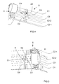
- the first member O1 is made under the shape of an axis of small extension, extending obliquely in the extension of the third body C3 (initially on the H-joint side).
- the second O2 member is here produced in the form of a arm rotatably mounted on the second body C2-1. It is more precisely consisting of an assembly of two bars with connected ends two by two, on one side by an axis of rotation AR secured to a spring RT printing a restoring force and secured to the second body C2-1, and the opposite side by a roll (or cylinder) RU rotatably mounted. Both bars, the roll RU and the rotation axis AR define an empty central space intended to receive the finger O1 as long as the second body C2-1 has not reached its limit position triggering the release of the third C3 and fourth C2-2 body.
- the third member O3 is here produced in the form of a cam whose lower profile at least partially reproduces the part of chosen kinematic of the second body C2-1, between its initial position and its limit position.
- the second member O2 is placed under the O3 cam. More precisely, its roll RU is constrained by the spring RT to rely against the lower part of the O3 cam.
- the finger O1 is thus blocked at inside the empty central space defined in the second organ O2, which forbidden to the third body C3 to carry out its personal kinematics (for example a rotation of about 180 °).
- the second organ O2 is forced to climb back along the O3 cam (its UK roll backing against the underside of the O3 cam by limiting friction) while retaining blocked finger O1, thus preventing rotation of the third body C3.
- the profile of the cam O3 stops which releases the front part of the second organ O2 (comprising the roll RU).
- the spring RT then forces the second organ O2 to make a rotation that frees the finger O1, then allowing the third C3 body to deploy.
- the release angle (here equal to 95 °) is here the angle from which the third body C3 can deploy without risk of hitting the first body C1, and without hindering the second body C2-1 during the terminal phase of its cinematic.
- FIG. 3 This example is a first variant of the second embodiment described above with reference to Figures 2A to 2C.
- the third member O3 presents itself in the form of a fixed cam whose lateral profile reproduces at least partially the selected kinematic part of the second body C2-1, between its initial position and its limit position.
- the first member O1 is in the form of a finger (or leg) fixedly mounted, via a support, at one end of the third body C3 and substantially parallel thereto.
- the second organ O2 is in the form of a arm mounted fixedly on the second body C2-1, and having a portion end with a groove G in which is rotatably mounted around of an axis AX a square EQ.
- a first part SP of the square EQ is provided with an end, preferably spherical, intended to support against the lateral surface of the cam O3, and a second portion DT of said EQ square, substantially perpendicular to the first SP, cooperates with the O1 finger.
- the first part SP of the square EQ is forced to slide along the O3 cam while the second part DT remains blocked by the finger O1, thus preventing the rotation of the third body C3.
- the profile of the O3 cam stops which releases the first part SP of the square EQ.
- the square EQ can then rotate, its second part DT releases the finger O1, thus allowing the third body C3 to deploy.
- FIG. 4 describes a fourth exemplary embodiment of a sequencing device according to the invention.
- This example is a second variant of the second embodiment described above with reference to Figures 2A to 2C.
- the third member O3 presents itself in the form of a fixed cam whose lateral profile reproduces at least partially the selected kinematic part of the second body C2-1, between its initial position and its limit position.
- the first member O1 is in the form of a notch or finger fixedly mounted to one end of the third body C3 and substantially in the extension of the latter.
- the second organ O2 is in the form of a arm fixedly mounted on the second body C2-1, in a plane substantially perpendicular to the latter, and whose terminal part (opposite to the fixation) has an AT axis.
- This axis AT is mounted in translation substantially perpendicular to the O2 arm and the O1 finger. It includes a first end part clean to block the finger O1 and a second part end, opposite the first and provided with a spring RT 'generating a recall force.
- the second end portion is intended to support, under the stress of the spring RT ', against the lateral profile of the cam O3.
- the lateral profile of the O3 cam prohibits any translation of the AT axis the second organ O2.
- the axis TA of the second organ O2 is forced to slide along the O3 cam (its second part end bearing against the lateral profile of the cam O3), thus blocking the O1 finger and preventing the rotation of the third body C3.
- the profile of the O3 cam stops which allows the AT axis to translate under the action of the spring RT ', in a direction opposite to the finger O1. Translation releasing the finger O1, the third body C3 can then be deployed.
- FIG. 5 This example is a third variant of the second embodiment described above with reference to Figures 2A to 2C.
- the third member O3 presents itself in the form of an arm fixedly mounted on the first body C1, in a plane substantially perpendicular to the latter and very obliquely in direction of the second C2-1 and third C3 body, and comprising a portion terminal (opposite the fixing) provided with a groove G '.
- the first member O1 is in the form of a mounted finger fixed at one end of the third body C3 and substantially in the extension of the latter preferably very slightly oblique.
- the groove G 'of the third member O3 and the end of the finger O1 are placed at substantially the same level and spaced by a selected distance.
- the second organ O2 is in the form of a arm fixedly mounted on the second body C2-1, in a plane substantially perpendicular to the latter, and whose terminal part (opposite to the fixation) is intended to be initially intercalated substantially between the groove G 'of the third member O3 and the end of the finger O1.
- This terminal part is provided with a bar B rotatably mounted, and preferably slightly flattened.
- This bar B has two free end portions, a first end being intended to be housed in the groove G 'of the third member O3 and a second end being intended to block the end of the finger O1.
- the first end of the bar B of the second member 02 is immobilized in the groove G 'of the third member 03, so that the bar B can not turn and blocks the 01 finger, thus preventing the third body C3 to perform his personal kinematics (for example a rotation about 180 °).
- the bar B of the second organ 02 forbids any finger movement O1 and therefore any rotation of the third body C3. Beyond these 95 °, the first end of the bar B comes out of the groove G 'of the third organ O3, so that the bar B can turn around of its axis of rotation thus releasing the finger O1 and allowing the third C3 body to deploy.
- Sequences controlled by devices according to the invention D can relate to many situations schematically illustrated, for some of them, in Figures 6 to 11.
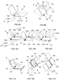
- the sequencing illustrated in FIGS. 6A and 6B relates to a structure S comprising a first fixed body (or panel) C1, a second body (or panel) C2 mounted movably on the first body C1 thanks to a joint installed in part on a first end EX11, and a third body C3 movably mounted on the second body C2 by means of a articulation installed on a first end EX21 and on a second EX12 end of the second body, opposite to its first EX11.
- the first C1, second C2 and third C3 bodies are here substantially parallel to each other, the third body C3 being initially interposed between the first C1 and second C2 body.
- the sequencing device according to the invention D here comprises of a first part, a first organ O1 (materialized by a black rectangle and by example arranged in the form of a finger), mounted on a second end EX22 of the third body C3, opposite its first end EX21, of a second part, a second organ O2 (materialized by a light gray triangle and for example arranged in the form of an arm), mounted on the first end EX11 of the second body C2, and a third part, a third organ O3 (materialized by a dark gray circle and for example arranged under the form of a cam), fixedly mounted on the first body C1.
- a first organ O1 materialized by a black rectangle and by example arranged in the form of a finger
- a second organ O2 materialized by a light gray triangle and for example arranged in the form of an arm
- a third organ O3 materialized by a dark gray circle and for example arranged under the form of a cam
- the dots embody the limit position beyond of which the third organ O3 releases the second organ O2 which releases to turn the first organ 01.
- the solid lines materialize the deployment of the third body C3, once the second body C2 has exceeded its position limit, and the dotted lines materialize the final (deployed) position of the structure S.
- the second body C2 continues its course (or trajectory or kinematics) on a small sector angular (typically 15 °), after reaching its limit position.
- FIGS. 7A and 7B The sequencing illustrated in FIGS. 7A and 7B is intended to show the relative nature of the movements of a body in relation to a other.
- This sequencing relates to a structure S comprising a first body (or panel) C1, a second body (or panel) C2 mounted mobile relative to the first body C1 thanks to a joint installed in part on a first end EX11, and a third body C3 mounted mobile on the second body C2 thanks to a joint installed in part on a first end EX21.
- the first C1, second C2 and third C3 body are here substantially parallel to each other, the third body C3 being initially interposed between the first C1 and second C2 body.
- the sequencing device according to the invention D here comprises of a first part, a first organ 01 (materialized by a black rectangle and by example arranged in the form of a finger), mounted on a second end EX22 of the third body C3, opposite its first end EX21, of a second part, a second organ 02 (materialized by a light gray triangle and for example arranged in the form of an arm), mounted on the first end EX11 of the second body C2, and a third part, a third organ O3 (materialized by a dark gray circle and for example arranged under the form of a cam), fixedly mounted on the first body C1.
- a first organ 01 materialized by a black rectangle and by example arranged in the form of a finger
- a second organ 02 materialized by a light gray triangle and for example arranged in the form of an arm
- a third organ O3 materialized by a dark gray circle and for example arranged under the form of a cam
- the fixed frame of reference is placed on the second body C2 which is therefore "Fixed". It can be noted that by moving the fixed frame on the first body C1 we obtain the arrangement of Figure 6, which shows the relative character movements of the bodies relative to each other. In others terms, it is equivalent according to the invention to move the second body by compared to the first body, when the latter is fixed, and to move the first body compared to the second body, when the latter is fixed (as it is the case in the example of Figures 7A and 7B).
- the dotted lines represent the limit position (relative) beyond which the third member 03 releases the second member 02 which releases in turn the first organ 01.
- the third body C3 remains substantially stationary with respect to the second body C2.
- the third body C3 is released and can unfold to reach its final position (materialized by the solid line of left in FIG. 7B), and at the same time the first body C1 continues its course (or trajectory or kinematics) towards its final position (materialized dotted on the right in Figure 7B), which defines the final position of the second body C2 with respect to him.
- the sequencing illustrated in FIGS. 8A and 8B relates to a S structure comprising a first body (or panel) C1, a second body (or panel) C2 movably mounted on the first body C1 by means of a articulation installed on a first axis of rotation A1, and a third body C3 mounted mobile on the first body C1 thanks to a joint installed on a second axis of rotation A2, substantially perpendicular to the first axis A1.
- the first C1, second C2 and third C3 bodies are here substantially parallel to each other, the third body C3 being initially interposed between the first C1 and second C2 body.
- the first body (or panel) C1 is here fixed but as in the previous example the second body could be fixed in place of the first.
- the sequencing device according to the invention D here comprises of a first part, a first organ 01 (materialized by a black rectangle and by example arranged in the form of a finger), mounted on the third body C3, a second part, a second organ 02 (materialized by a gray triangle clear and for example arranged in the form of an arm), mounted on the second body C2, and thirdly, a third organ 03 (materialized by a dark gray round and for example arranged in the form of a cam), mounted fixed on the first body C1.
- the third body C3 remains substantially stationary with respect to the first body C1 as long as the second body C2 has not not reached its limit position shown in dotted lines in Figure 8A and in solid lines in Figure 8B.
- the third organ 03 releases the second member 02 which in turn releases the first member 01.
- third body C3 is then released and can deploy to join his final position (represented by the solid lines on the right in FIG. 8B), and at the same time the second body C2 continues its course (or trajectory or kinematic) towards its final position (materialized by the dots at left in Figure 8B).
- the sequencing illustrated in FIGS. 9A and 9B relates to a structure S comprising a first fixed body (or panel) C1, a second body (or panel) C2 movably mounted on the first body C1 by means of a articulation installed on a first axis of rotation A1, and a third body C3 mounted mobile on the second body C2 thanks to an installed joint on a second axis of rotation A2, substantially perpendicular to the first axis A1.
- the first C1, second C2 and third C3 bodies are here substantially parallel to each other, the third body C3 being initially interposed between the first C1 and second C2 body.
- the sequencing device according to the invention D here comprises of a first part, a first organ 01 (materialized by a black rectangle and by example arranged in the form of a finger), mounted on the third body C3, a second part, a second organ 02 (materialized by a gray triangle clear and for example arranged in the form of an arm), mounted on the second body C2, and thirdly, a third organ 03 (materialized by a dark gray round and for example arranged in the form of a cam), mounted fixed on the first body C1 at the first axis of rotation A1.
- the third body C3 follows the path (or kinematics) of the second body C2 as long as it has not reached its limit position shown in dashed lines in FIG. 9A and in solid lines on the Figure 9B. Once this is reached, the third organ O3 releases the second organ O2 which releases in turn the first organ O1. The third body C3 is then released and can deploy to reach its final position (shown by the solid lines on the right in Figure 9B), next to second body C2, and at the same time the second body C2 continues its course (or trajectory or kinematics) towards its final position (materialized by the dotted lines on the left in Figure 9B), training with him the third body C3.
- the sequencing illustrated in FIGS. 10A to 10C relates to a structure S comprising a first fixed body (or panel) C1, a second body (or panel) C2 movably mounted on the first body C1 by means of a articulation installed on a first axis of rotation A1, and a third body C3 mounted mobile on the first body C1 thanks to a joint installed on a second axis of rotation A2, substantially perpendicular to the first axis A1.
- the first C1, second C2 and third C3 bodies are here substantially parallel to each other, the third body C3 being initially interposed between the first C1 and second C2 body.
- the structure S is here equipped with two sequencing devices according to the invention D1 and D2.
- the first sequencing device D1 here comprises of a first part, a first organ O11 (materialized by a black rectangle and by example arranged in the form of a finger), mounted on the third body C3, a second part, a second organ O21 (materialized by a triangle light gray and for example arranged in the form of an arm), mounted on the second body C2, and a third part, a third organ O31 (materialized by a dark gray circle and for example arranged in the form of a cam), fixedly mounted on the first body C1 at the first axis of rotation A1.
- a first organ O11 materialized by a black rectangle and by example arranged in the form of a finger
- a second organ O21 materialized by a triangle light gray and for example arranged in the form of an arm
- a third organ O31 materialized by a dark gray circle and for example arranged in the form of a cam
- the second sequencing device D2 here comprises of a first part, a first organ O12 (materialized by a black rectangle and by example arranged in the form of a finger), mounted on the second body C2, a second part, a second organ 022 (materialized by a triangle light gray and for example arranged in the form of an arm), mounted on the third body C3, and a third part, a third organ 032 (materialized by a dark gray circle and for example arranged in the form of a cam), fixedly mounted on the first body C1 at the second axis of rotation A2.
- the first sequencing device D1 controls triggering the deployment of the third body C3, while the second sequencing device D2 controls the triggering of the final deployment of the second body C2.
- the third body C3 remains substantially stationary with respect to the first body C1 as long as the second body C2 has not not reached its limit position shown in dashed lines in Figure 10A and in solid lines in FIGS. 10B and 10C.
- the third member 031, of the first device D1 releases the second member 021 which releases in turn the first organ 011.
- the third body C3 is then released and can deploy to reach its limit (and final) position materialized by the dots in Figure 10B and the solid lines in Figure 10C.
- the second body C2 remains substantially stationary in its limit position as long as the third body C3 has not reached its own limit position.
- the third member 032 of the second device D2 releases the second member 022 which in turn releases the first member 012.
- second body C2 is then released and can finish deploying to join its final position materialized by the dashed lines in Figure 10C (which is to go back slightly).
- the sequencing illustrated in FIGS. 11A-11C relates to a structure S comprising a first fixed body (or panel) C1, a second body (or panel) C2 movably mounted on the first body C1 by means of a articulation installed on a first axis of rotation A1, a third body C3 movably mounted on the second body C2 by virtue of an articulation installed on a second axis of rotation A2, substantially perpendicular to the first A1 axis, a fourth body C4 movably mounted on the second body C2 through to an articulation installed on a third axis of rotation A3, substantially parallel to the second axis A2, and a fifth body C5 mounted mobile on the fourth body C4 through an articulation installed on a fourth axis of rotation A4, substantially parallel to the first axis A1 and substantially perpendicular to the third axis A3.
- the first C1, second C2, third C3, fourth C4 and fifth C5 bodies are here initially substantially parallel to each other, the third body C3 being interposed between the first C1 and fifth C5 body, the fifth body C5 being interposed between the third C3 and fourth C4 body, and the fourth body C4 being interspersed between the second C2 and fifth C5 body.
- the second C2, third C3, fourth C4 and fifth C5 body constitute a first subset E1
- the fourth C4 and fifth C5 bodies constitute a second subset E2.
- the structure S is here equipped with two sequencing devices according to the invention D1 and D2.
- the first sequencing device D1 here comprises of a first part, a first organ O111 (materialized by a black rectangle and for example arranged in the form of a finger), mounted on the third body C3, of a second part, another first organ O112 (materialized by a black rectangle and for example arranged in the form of a finger), mounted on the fourth body C4, a third part, a second body O21 (materialized by a light gray triangle and for example arranged in the form of an arm), mounted on the second body C2, and a third part, a third organ O31 (materialized by a dark gray circle and for example arranged in the form of a cam), fixedly mounted on the first body C1 at the first axis of rotation A1.
- a first organ O111 materialized by a black rectangle and for example arranged in the form of a finger
- another first organ O112 materialized by a black rectangle and for example arranged in the form of a finger
- mounted on the fourth body C4 a third part
- the second sequencing device D2 here comprises of a first part, a first organ 012 (materialized by a black rectangle and by example arranged in the form of a finger), mounted on the fifth body C5, a second part, a second organ 022 (materialized by a triangle light gray and for example arranged in the form of an arm), mounted on the fourth body C4, and a third part, a third organ O32 (materialized by a dark gray circle and for example arranged in the form of a cam), fixedly mounted on the second body C2 at the third axis rotation A3.
- the first sequencing device D1 controls triggering the deployment of the third body C3 and the second subset E2 (C4 and C5), while the second sequencing device D2 controls the triggering of the final deployment of the fifth body C5.
- the second body C2 causes it to travel (or trajectory or kinematics) all the first subset E1 until it reaches its limit position shown in dashed lines in FIG. 11A and in full lines in Figure 11B.
- the third organ O31, of the first device D1 releases the second member 021 which releases to its turn the first organs O111 and O112.
- the third body C3 and the second subset E2 are then released and can deploy to join their respective final positions (represented by the dashed lines in the figure 11B and by the solid lines in FIG. 11C), on both sides of the second C2 body.
- the third member 032, of the second device D2 releases the second member O22 which in turn releases the first organ 012.
- the fifth body C5 is then released and can deploy to reach its final position (materialized by the dots in Figure 11C).
- a body can be considered as fixed with respect to a device sequencing and mobile vis-à-vis another sequencing device, because of the relative nature of the movements of the bodies relative to each other to others.
- the third body was generally interposed between the first and second bodies. But this is not not mandatory.
- the third body can indeed be placed above (or against, or in the vicinity of) the first and second bodies, from that it is rotatably mounted on one of them.
Landscapes
- Engineering & Computer Science (AREA)
- Remote Sensing (AREA)
- Aviation & Aerospace Engineering (AREA)
- Aerials With Secondary Devices (AREA)
- Photovoltaic Devices (AREA)
- Details Of Aerials (AREA)
- Prostheses (AREA)
- Toys (AREA)
- Mechanical Control Devices (AREA)
- Bridges Or Land Bridges (AREA)
- Absorbent Articles And Supports Therefor (AREA)
- Ultra Sonic Daignosis Equipment (AREA)
Abstract
Description
- le premier corps peut comprendre un troisième organe fixe agencé de manière à contraindre le deuxième organe à bloquer le premier organe tant que le deuxième corps n'a pas effectué la partie de cinématique choisie. Dans ce cas, le troisième organe est par exemple une came dont la forme est choisie de manière à « reproduire » au moins partiellement la partie de cinématique choisie,
- lorsque la partie terminale du bras comporte un axe (ou une barre), celui-ci peut comprendre des première et seconde portions faisant saillie de part et d'autre de la partie terminale. La première portion est alors agencée de manière à bloquer le doigt, et la seconde portion comprend une extrémité chargée de glisser le long de la came pendant la partie de cinématique choisie. Dans ce cas, la barre (ou l'axe) est par exemple capable de se translater sous l'effet d'une force de rappel sensiblement perpendiculairement au premier bras lorsque l'extrémité de sa seconde portion n'est plus au contact de la came afin de passer d'une première position dans laquelle il bloque le doigt vers une seconde position dans laquelle il libère ledit doigt,
- en variante, le bras peut être monté à rotation sur le deuxième corps, sous contrainte d'une force de rappel, et sa partie terminale peut être placée dans une première position dans laquelle elle suit un profil de la came (qui reproduit la partie de cinématique choisie), tout en bloquant le doigt lorsque le deuxième corps se déplace vers sa position finale, et dans une seconde position dans laquelle elle libère le doigt lorsqu'elle n'est plus contrainte à suivre le profil de came. Dans ce cas, la partie terminale du bras comporte par exemple un cylindre (ou rouleau) monté à rotation et pouvant s'appuyer contre le profil de came,
- dans une autre variante, le doigt est toujours dans le prolongement du troisième corps, et le bras comprend une partie terminale comportant une gorge dans laquelle est montée à rotation une équerre comprenant une première partie s'appuyant contre la came pendant la partie de cinématique choisie et une seconde partie chargée de bloquer le doigt,
- dans une autre variante, le troisième organe peut être un second bras muni d'une partie terminale comportant une gorge, et la barre (ou axe) est montée à rotation à l'extrémité du premier bras et comporte des première et seconde portions faisant saillie, en position de blocage, de part et d'autre de la partie terminale du premier bras. La première portion est alors chargée de bloquer le doigt lorsque la seconde portion est logée dans la gorge, c'est-à-dire tant que le deuxième corps n'a pas effectué la partie de cinématique.
- les figures 1A à 1C illustrent respectivement trois états d'un premier exemple de réalisation d'un dispositif de séquencement selon l'invention,
- les figures 2A à 2C illustrent respectivement trois états d'un deuxième exemple de réalisation d'un dispositif de séquencement selon l'invention,
- la figure 3 illustre un troisième exemple de réalisation d'un dispositif de séquencement selon l'invention,
- la figure 4 illustre un quatrième exemple de réalisation d'un dispositif de séquencement selon l'invention,
- la figure 5 illustre un cinquième exemple de réalisation d'un dispositif de séquencement selon l'invention,
- les figures 6A et 6B illustrent respectivement, de façon schématique, deux phases de déploiement de panneaux d'un premier exemple de structure déployable, mettant en oeuvre un unique dispositif de séquencement selon l'invention,
- les figures 7A et 7B illustrent respectivement, de façon schématique, deux phases de déploiement de panneaux d'un deuxième exemple de structure déployable, mettant en oeuvre un unique dispositif de séquencement selon l'invention,
- les figures 8A et 8B illustrent respectivement, de façon schématique, deux phases de déploiement de panneaux d'un troisième exemple de structure déployable, mettant en oeuvre un unique dispositif de séquencement selon l'invention,
- les figures 9A et 9B illustrent respectivement, de façon schématique, deux phases de déploiement de panneaux d'un quatrième exemple de structure déployable, mettant en oeuvre un unique dispositif de séquencement selon l'invention,
- les figures 10A à 10C illustrent respectivement, de façon schématique, trois phases de déploiement de panneaux d'un cinquième exemple de structure déployable, mettant en oeuvre deux dispositifs de séquencement selon l'invention, et
- les figures 11A à 11C illustrent respectivement, de façon schématique, trois phases de déploiement de panneaux d'un sixième exemple de structure déployable, mettant en oeuvre deux dispositifs de séquencement selon l'invention.
Claims (18)
- Dispositif de séquencement (D) pour une structure déployable (S) comprenant un premier corps (C1), au moins un deuxième corps (C2) mobile par rapport audit premier corps (C1) et au moins un troisième corps (C3) mobile par rapport à l'un desdits premier (C1) et deuxième (C2) corps et placé, en position au moins partiellement repliée de la structure (S), contre ou entre lesdits premier (C1) et deuxième (C2) corps, caractérisé en ce qu'il comprend un premier organe (O1) monté fixement sur ledit troisième corps (C3) et propre à interdire son déploiement lorsqu'il est bloqué, et un deuxième organe (02) monté sur ledit deuxième corps (C2) et agencé de manière à bloquer ledit premier organe (O1) tant que ledit deuxième corps (C2) n'a pas effectué une partie choisie d'une cinématique destinée à l'entraíner d'une position initiale vers une position finale.
- Dispositif selon la revendication 1, caractérisé en ce que ledit premier organe (O1) est agencé sous la forme d'un doigt et ledit deuxième organe (O2) est agencé sous la forme d'un premier bras comprenant une partie terminale conformée de manière à bloquer ledit doigt (O1).
- Dispositif selon la revendication 2, caractérisé en ce que ladite partie terminale comporte un axe (B, AT) sensiblement perpendiculaire audit premier bras (O2) et propre à bloquer ledit doigt (O1).
- Dispositif selon l'une des revendications 1 à 3, caractérisé en ce que ledit premier corps (C1) comprend un troisième organe (O3) fixe agencé de manière à contraindre ledit deuxième organe (O2) à bloquer ledit premier organe (O1) tant que ledit deuxième corps (C2) n'a pas effectué ladite partie de cinématique choisie.
- Dispositif selon la revendication 4, caractérisé en ce que ledit troisième organe (O3) est une came de forme choisie de manière à reproduire au moins partiellement ladite partie de cinématique choisie.
- Dispositif selon la combinaison des revendications 3 et 5, caractérisé en ce que ledit axe (AT) comporte des première et seconde portions faisant saillie de part et d'autre de ladite partie terminale du premier bras (O2), ladite première portion étant agencée de manière à bloquer ledit doigt (O1), et ladite seconde portion comprenant une extrémité agencée de manière à glisser le long de ladite came (O3) pendant ladite partie de cinématique choisie.
- Dispositif selon la revendication 6, caractérisé en ce que ledit axe (AT) est propre à se translater, sous l'effet d'une force de rappel, sensiblement perpendiculairement audit premier bras (O2) lorsque l'extrémité de sa seconde portion n'est plus au contact de ladite came (O3), de manière à passer d'une première position dans laquelle il bloque ledit doigt (O1) vers une seconde position dans laquelle il libère ledit doigt (O1).
- Dispositif selon la combinaison des revendications 3 et 5, caractérisé en ce que ledit bras (O2) est monté à rotation sur ledit deuxième corps (C2), sous contrainte d'une force de rappel, et sa partie terminale est propre à être placée dans une première position dans laquelle elle suit un profil de ladite came (O3), qui reproduit ladite partie de cinématique choisie, tout en bloquant ledit doigt (O1) lorsque ledit deuxième corps (C2) se déplace vers sa position finale, et dans une seconde position dans laquelle elle libère ledit doigt (O1) lorsqu'elle n'est plus contrainte à suivre ledit profil de came (O3).
- Dispositif selon la revendication 8, caractérisée en ce que ladite partie terminale du bras comporte un cylindre (RU) monté à rotation et propre à s'appuyer contre ledit profil de came (O3).
- Dispositif selon la combinaison des revendications 2 et 5, caractérisé en ce que ledit doigt (O1) est sensiblement dans le prolongement dudit troisième corps (C3), et en ce que ladite partie terminale du bras (O2) comporte une gorge (G) dans laquelle est montée à rotation une équerre (EQ) comprenant une première partie (SP) agencée de manière à s'appuyer contre ladite came (O3) pendant la partie de cinématique choisie et une seconde partie (DT) agencée de manière à bloquer ledit doigt (O1) pendant ladite partie de cinématique choisie.
- Dispositif selon la combinaison des revendications 3 et 4, caractérisé en ce que ledit troisième organe (03) est un second bras muni d'une partie terminale comportant une gorge (G'), et en ce que ledit axe (B) est monté à rotation à l'extrémité dudit premier bras (02) et comporte des première et seconde portions faisant saillie, en position de blocage, de part et d'autre de la partie terminale du premier bras, ladite première portion étant agencée de manière à bloquer ledit doigt (O1) lorsque ladite seconde portion est logée dans ladite gorge (G'), et ladite seconde portion étant agencée de manière à demeurer logée dans la gorge (G') tant que ledit deuxième corps (C2) n'a pas effectué ladite partie de cinématique choisie.
- Structure déployable (S) comprenant un premier corps (C1), au moins un deuxième corps (C2) mobile par rapport audit premier corps (C1) et au moins un troisième corps (C3) mobile par rapport à l'un desdits premier (C1) et deuxième (C2) corps et placé, en position repliée de la structure, contre ou entre lesdits premier (C1) et deuxième (C2) corps, caractérisé en ce qu'il comprend au moins un dispositif de séquencement (D) selon l'une des revendications précédentes.
- Structure selon la revendication 12, caractérisée en ce que ladite partie de cinématique choisie du deuxième corps (C2) est constituée d'au moins une rotation pure sur un secteur angulaire choisi.
- Structure selon la revendication 12, caractérisée en ce que ladite partie de cinématique choisie du deuxième corps (C2) est constituée d'au moins une translation pure sur une distance choisie.
- Structure selon la revendication 12, caractérisée en ce que ladite partie de cinématique choisie du deuxième corps (C2) est une combinaison d'au moins une rotation pure sur un secteur angulaire choisi et/ou d'au moins une translation pure sur une distance choisie.
- Structure selon l'une des revendications 12 à 15, caractérisée en ce que l'un au moins desdits corps (C1-C3) constitue au moins une partie d'une antenne de télécommunications.
- Structure selon l'une des revendications 12 à 16, caractérisée en ce que l'un au moins desdits corps (C1-C3) constitue au moins une partie d'un générateur solaire.
- Structure selon l'une des revendications 12 à 17, caractérisée en ce que l'un au moins desdits corps (C1-C3) constitue au moins une partie d'un dispositif de transfert de chaleur.
Applications Claiming Priority (2)
| Application Number | Priority Date | Filing Date | Title |
|---|---|---|---|
| FR0315224A FR2864033B1 (fr) | 2003-12-23 | 2003-12-23 | Dispositif de sequencement pour une structure deployable en fonction de la cinematique de l'un de ses corps mobiles |
| FR0315224 | 2003-12-23 |
Publications (2)
| Publication Number | Publication Date |
|---|---|
| EP1547923A1 true EP1547923A1 (fr) | 2005-06-29 |
| EP1547923B1 EP1547923B1 (fr) | 2009-05-06 |
Family
ID=34531325
Family Applications (1)
| Application Number | Title | Priority Date | Filing Date |
|---|---|---|---|
| EP04293064A Expired - Lifetime EP1547923B1 (fr) | 2003-12-23 | 2004-12-20 | Dispositif de séquencement pour une structure déployable en fonction de la cinématique de l'un de ses corps mobiles |
Country Status (7)
| Country | Link |
|---|---|
| US (1) | US7708228B2 (fr) |
| EP (1) | EP1547923B1 (fr) |
| JP (1) | JP4124766B2 (fr) |
| AT (1) | ATE430693T1 (fr) |
| DE (1) | DE602004020963D1 (fr) |
| ES (1) | ES2327122T3 (fr) |
| FR (1) | FR2864033B1 (fr) |
Cited By (1)
| Publication number | Priority date | Publication date | Assignee | Title |
|---|---|---|---|---|
| FR2902082A1 (fr) * | 2006-06-12 | 2007-12-14 | Alcatel Sa | Systeme de deploiement d'appendices spatiaux et appendice spatial comportant un tel systeme |
Families Citing this family (15)
| Publication number | Priority date | Publication date | Assignee | Title |
|---|---|---|---|---|
| US8019394B2 (en) * | 2007-06-29 | 2011-09-13 | Motorola Mobility, Inc. | Component packaging for handheld communication devices |
| US20090170571A1 (en) * | 2007-12-31 | 2009-07-02 | Motorola, Inc. | Method and apparatus for partial flip-open assist of ultra thin clam communication devices |
| US8204560B2 (en) * | 2008-12-17 | 2012-06-19 | Motorola Mobility, Inc. | Clamshell phone with edge access |
| US8757554B1 (en) * | 2009-09-09 | 2014-06-24 | MMA Design, LLC | Deployable and tracked solar array mechanism for nano-satellites |
| US10370126B1 (en) | 2009-09-09 | 2019-08-06 | M.M.A. Design, LLC | Solar panel array assembly |
| US8683755B1 (en) * | 2010-01-21 | 2014-04-01 | Deployable Space Systems, Inc. | Directionally controlled elastically deployable roll-out solar array |
| US8915474B1 (en) | 2012-09-21 | 2014-12-23 | Space Systems/Loral, Llc | Solar panel sequencing mechanism |
| US9004410B1 (en) | 2014-10-24 | 2015-04-14 | Alliance Spacesystems, Llc | Deployable boom for collecting electromagnetic energy |
| US10059471B2 (en) | 2014-10-24 | 2018-08-28 | Solaero Technologies Corp. | Method for releasing a deployable boom |
| US11492145B2 (en) | 2016-12-19 | 2022-11-08 | Mitsubishi Electric Corporation | Deployable radiator |
| US11148831B2 (en) * | 2017-11-10 | 2021-10-19 | Spire Global, Inc. | Systems and methods for satellite solar panel deployment |
| US11148834B2 (en) * | 2017-11-10 | 2021-10-19 | Spire Global, Inc. | Systems and methods for satellite solar panel stowage and deployment |
| WO2019150873A1 (fr) * | 2018-02-01 | 2019-08-08 | 日本電気株式会社 | Dispositif et procédé de déploiement de panneau |
| KR102556170B1 (ko) * | 2021-09-03 | 2023-07-18 | 한국항공우주연구원 | 위성 용 전개형 구조물 장탈착 장치 |
| CN113928606B (zh) * | 2021-11-22 | 2023-04-21 | 北京卫星环境工程研究所 | 一种航天器多次对接与分离信号模拟装置 |
Citations (4)
| Publication number | Priority date | Publication date | Assignee | Title |
|---|---|---|---|---|
| FR2768400A1 (fr) * | 1997-09-17 | 1999-03-19 | Aerospatiale | Dispositif de verrouillage temporaire de panneaux d'un generateur solaire l'un a l'autre pour le sequencement du deploiement de ces panneaux |
| US5909860A (en) * | 1998-02-26 | 1999-06-08 | Hughes Electronics Corporation | Deployment sequencer |
| FR2781454A1 (fr) * | 1998-07-22 | 2000-01-28 | Loral Space Systems Inc | Dispositif de retenue et de mise en sequence de deploiement |
| US6484972B1 (en) * | 1999-11-04 | 2002-11-26 | Alcatel | Articulated set of sequentially opened solar generator panels |
Family Cites Families (10)
| Publication number | Priority date | Publication date | Assignee | Title |
|---|---|---|---|---|
| US3699576A (en) * | 1970-07-07 | 1972-10-17 | Fairchild Industries | Collapsible reflector |
| FR2200856A5 (fr) * | 1972-09-28 | 1974-04-19 | France Etat | |
| US4529277A (en) * | 1982-04-28 | 1985-07-16 | British Aerospace Public Limited Company | Foldable reflector |
| US4510637A (en) * | 1983-03-14 | 1985-04-16 | Lucjan Zlotnicki | Bridge launcher |
| US4602399A (en) * | 1984-05-24 | 1986-07-29 | Harsco Corporation | Bridge transporting and launching trailer and method |
| DE3615264A1 (de) * | 1986-05-06 | 1987-11-12 | Messerschmitt Boelkow Blohm | Vorrichtung fuer die teilentfaltung von solargeneratoren |
| US5319905A (en) * | 1992-09-28 | 1994-06-14 | Spar Aerospace Limited | Panel array deployment apparatus |
| US6478261B2 (en) * | 1998-11-02 | 2002-11-12 | Trw Inc. | Spacecraft with deployable panel array |
| US6158088A (en) * | 1999-04-05 | 2000-12-12 | Lockheed Martin Corporation | Deployable hinge assembly providing end of travel damping |
| US6191757B1 (en) * | 1999-04-08 | 2001-02-20 | Hughes Electronics Corporation | System for compact stowage of segmented dish reflectors |
-
2003
- 2003-12-23 FR FR0315224A patent/FR2864033B1/fr not_active Expired - Fee Related
-
2004
- 2004-12-20 AT AT04293064T patent/ATE430693T1/de active
- 2004-12-20 ES ES04293064T patent/ES2327122T3/es not_active Expired - Lifetime
- 2004-12-20 EP EP04293064A patent/EP1547923B1/fr not_active Expired - Lifetime
- 2004-12-20 DE DE602004020963T patent/DE602004020963D1/de not_active Expired - Lifetime
- 2004-12-21 US US11/017,099 patent/US7708228B2/en not_active Expired - Lifetime
- 2004-12-22 JP JP2004370528A patent/JP4124766B2/ja not_active Expired - Fee Related
Patent Citations (4)
| Publication number | Priority date | Publication date | Assignee | Title |
|---|---|---|---|---|
| FR2768400A1 (fr) * | 1997-09-17 | 1999-03-19 | Aerospatiale | Dispositif de verrouillage temporaire de panneaux d'un generateur solaire l'un a l'autre pour le sequencement du deploiement de ces panneaux |
| US5909860A (en) * | 1998-02-26 | 1999-06-08 | Hughes Electronics Corporation | Deployment sequencer |
| FR2781454A1 (fr) * | 1998-07-22 | 2000-01-28 | Loral Space Systems Inc | Dispositif de retenue et de mise en sequence de deploiement |
| US6484972B1 (en) * | 1999-11-04 | 2002-11-26 | Alcatel | Articulated set of sequentially opened solar generator panels |
Cited By (4)
| Publication number | Priority date | Publication date | Assignee | Title |
|---|---|---|---|---|
| FR2902082A1 (fr) * | 2006-06-12 | 2007-12-14 | Alcatel Sa | Systeme de deploiement d'appendices spatiaux et appendice spatial comportant un tel systeme |
| WO2007144329A1 (fr) * | 2006-06-12 | 2007-12-21 | Thales | Systeme de deploiement d'appendices spatiaux et appendice spatial comportant un tel systeme |
| JP2009539688A (ja) * | 2006-06-12 | 2009-11-19 | テールズ | 空間的付加物展開用装置およびそのような装置を備える空間的付加物 |
| US8245587B2 (en) | 2006-06-12 | 2012-08-21 | Thales | System for deploying spatial appendices and spatial appendix comprising such a system |
Also Published As
| Publication number | Publication date |
|---|---|
| US20050156083A1 (en) | 2005-07-21 |
| JP4124766B2 (ja) | 2008-07-23 |
| FR2864033A1 (fr) | 2005-06-24 |
| ATE430693T1 (de) | 2009-05-15 |
| ES2327122T3 (es) | 2009-10-26 |
| JP2005178773A (ja) | 2005-07-07 |
| EP1547923B1 (fr) | 2009-05-06 |
| FR2864033B1 (fr) | 2007-01-19 |
| US7708228B2 (en) | 2010-05-04 |
| DE602004020963D1 (de) | 2009-06-18 |
Similar Documents
| Publication | Publication Date | Title |
|---|---|---|
| EP1547923B1 (fr) | Dispositif de séquencement pour une structure déployable en fonction de la cinématique de l'un de ses corps mobiles | |
| EP1555171B1 (fr) | Lève capot à actionneur muni d'un système de verrouillage par crochet | |
| EP0888964B1 (fr) | Perfectionnements aux dispositifs pour le repliage d'une pale de rotor de giravion | |
| FR2766137A1 (fr) | Siege de vehicule equipe d'un mecanisme d'articulation | |
| CA2693091C (fr) | Chaine porteuse de cables pour volet mobile de bord d'attaque d'une aile d'aeronef | |
| FR2583113A1 (fr) | Mecanisme d'indexage pour turbine a air utilisant la pression dynamique | |
| CA1230869A (fr) | Atterrisseur pour aeronef | |
| EP3060428B1 (fr) | Dispositif de blocage en position d'un element rabattable pour un siege de vehicule | |
| CA2324886C (fr) | Dispositif de commande d'une rotation relative entre deux elements articules et structure deployable, notamment pour vehicule spatial, utilisant au moins un dispositif de ce type | |
| FR2766138A1 (fr) | Mecanisme d'articulation pour siege de vehicule, et siege de vehicule equipe d'un tel mecanisme | |
| FR2851211A1 (fr) | Siege rabattable et vehicule comportant un tel siege | |
| EP2042427A1 (fr) | Marchepied repliable d'un véhicule et véhicule muni d'un tel marchepied | |
| FR2941413A1 (fr) | Dispositif de reglage electrique d'un siege de vehicule | |
| EP2032438A1 (fr) | Articulation auto-motorisee pour ensemble articule tel qu'un panneau solaire de satellite | |
| FR2627150A1 (fr) | Articulation pour le deploiement en deux etapes d'un panneau solaire | |
| EP0691237B1 (fr) | Glissière pour siège de véhicule | |
| WO2011006746A2 (fr) | Train avant d'aeronef a dispositif de commande unique pour le relevage et la direction | |
| WO2015063423A1 (fr) | Ensemble de liaison par anneau d'arrêt pour tronçon d'arbre. procédé de montage d'un tel ensemble de liaison | |
| EP0032342B1 (fr) | Agencement de satellite artificiel pourvu de générateurs solaires et d'antennes déployables | |
| FR2853868A1 (fr) | Systeme de plage arriere escamotable pour vehicule decouvrable a toit repliable | |
| EP1516098B1 (fr) | Serrure pour ouvrant de vehicule automobile comportant des moyens de decondamnation interieure et exterieure | |
| WO2010122264A1 (fr) | Siège a dossier escamotable avec élément déployable et moyen de locomotion comprenant au moins un tel siège | |
| EP1368693A1 (fr) | Paire de lunettes a mecanisme d'ouverture automatique de branche | |
| FR2667842A1 (fr) | Mecanisme rotatif de vehicule spatial, a systeme de gerbage integre. | |
| EP1174894A1 (fr) | Sectionneur à couteau avec un système de blocage par passage de point mort |
Legal Events
| Date | Code | Title | Description |
|---|---|---|---|
| PUAI | Public reference made under article 153(3) epc to a published international application that has entered the european phase |
Free format text: ORIGINAL CODE: 0009012 |
|
| AK | Designated contracting states |
Kind code of ref document: A1 Designated state(s): AT BE BG CH CY CZ DE DK EE ES FI FR GB GR HU IE IS IT LI LT LU MC NL PL PT RO SE SI SK TR |
|
| AX | Request for extension of the european patent |
Extension state: AL BA HR LV MK YU |
|
| 17P | Request for examination filed |
Effective date: 20051214 |
|
| AKX | Designation fees paid |
Designated state(s): AT BE BG CH CY CZ DE DK EE ES FI FR GB GR HU IE IS IT LI LT LU MC NL PL PT RO SE SI SK TR |
|
| RAP1 | Party data changed (applicant data changed or rights of an application transferred) |
Owner name: ALCATEL LUCENT |
|
| GRAP | Despatch of communication of intention to grant a patent |
Free format text: ORIGINAL CODE: EPIDOSNIGR1 |
|
| GRAS | Grant fee paid |
Free format text: ORIGINAL CODE: EPIDOSNIGR3 |
|
| GRAA | (expected) grant |
Free format text: ORIGINAL CODE: 0009210 |
|
| AK | Designated contracting states |
Kind code of ref document: B1 Designated state(s): AT BE BG CH CY CZ DE DK EE ES FI FR GB GR HU IE IS IT LI LT LU MC NL PL PT RO SE SI SK TR |
|
| REG | Reference to a national code |
Ref country code: GB Ref legal event code: FG4D Free format text: NOT ENGLISH |
|
| RAP2 | Party data changed (patent owner data changed or rights of a patent transferred) |
Owner name: THALES |
|
| REG | Reference to a national code |
Ref country code: CH Ref legal event code: EP |
|
| REG | Reference to a national code |
Ref country code: IE Ref legal event code: FG4D |
|
| REF | Corresponds to: |
Ref document number: 602004020963 Country of ref document: DE Date of ref document: 20090618 Kind code of ref document: P |
|
| NLT2 | Nl: modifications (of names), taken from the european patent patent bulletin |
Owner name: THALES Effective date: 20090506 |
|
| REG | Reference to a national code |
Ref country code: ES Ref legal event code: FG2A Ref document number: 2327122 Country of ref document: ES Kind code of ref document: T3 |
|
| PG25 | Lapsed in a contracting state [announced via postgrant information from national office to epo] |
Ref country code: LT Free format text: LAPSE BECAUSE OF FAILURE TO SUBMIT A TRANSLATION OF THE DESCRIPTION OR TO PAY THE FEE WITHIN THE PRESCRIBED TIME-LIMIT Effective date: 20090506 Ref country code: PT Free format text: LAPSE BECAUSE OF FAILURE TO SUBMIT A TRANSLATION OF THE DESCRIPTION OR TO PAY THE FEE WITHIN THE PRESCRIBED TIME-LIMIT Effective date: 20090906 |
|
| PG25 | Lapsed in a contracting state [announced via postgrant information from national office to epo] |
Ref country code: SI Free format text: LAPSE BECAUSE OF FAILURE TO SUBMIT A TRANSLATION OF THE DESCRIPTION OR TO PAY THE FEE WITHIN THE PRESCRIBED TIME-LIMIT Effective date: 20090506 Ref country code: SE Free format text: LAPSE BECAUSE OF FAILURE TO SUBMIT A TRANSLATION OF THE DESCRIPTION OR TO PAY THE FEE WITHIN THE PRESCRIBED TIME-LIMIT Effective date: 20090806 Ref country code: PL Free format text: LAPSE BECAUSE OF FAILURE TO SUBMIT A TRANSLATION OF THE DESCRIPTION OR TO PAY THE FEE WITHIN THE PRESCRIBED TIME-LIMIT Effective date: 20090506 Ref country code: IS Free format text: LAPSE BECAUSE OF FAILURE TO SUBMIT A TRANSLATION OF THE DESCRIPTION OR TO PAY THE FEE WITHIN THE PRESCRIBED TIME-LIMIT Effective date: 20090906 |
|
| REG | Reference to a national code |
Ref country code: IE Ref legal event code: FD4D |
|
| PG25 | Lapsed in a contracting state [announced via postgrant information from national office to epo] |
Ref country code: CZ Free format text: LAPSE BECAUSE OF FAILURE TO SUBMIT A TRANSLATION OF THE DESCRIPTION OR TO PAY THE FEE WITHIN THE PRESCRIBED TIME-LIMIT Effective date: 20090506 Ref country code: IE Free format text: LAPSE BECAUSE OF FAILURE TO SUBMIT A TRANSLATION OF THE DESCRIPTION OR TO PAY THE FEE WITHIN THE PRESCRIBED TIME-LIMIT Effective date: 20090506 Ref country code: EE Free format text: LAPSE BECAUSE OF FAILURE TO SUBMIT A TRANSLATION OF THE DESCRIPTION OR TO PAY THE FEE WITHIN THE PRESCRIBED TIME-LIMIT Effective date: 20090506 Ref country code: DK Free format text: LAPSE BECAUSE OF FAILURE TO SUBMIT A TRANSLATION OF THE DESCRIPTION OR TO PAY THE FEE WITHIN THE PRESCRIBED TIME-LIMIT Effective date: 20090506 Ref country code: RO Free format text: LAPSE BECAUSE OF FAILURE TO SUBMIT A TRANSLATION OF THE DESCRIPTION OR TO PAY THE FEE WITHIN THE PRESCRIBED TIME-LIMIT Effective date: 20090506 |
|
| PG25 | Lapsed in a contracting state [announced via postgrant information from national office to epo] |
Ref country code: SK Free format text: LAPSE BECAUSE OF FAILURE TO SUBMIT A TRANSLATION OF THE DESCRIPTION OR TO PAY THE FEE WITHIN THE PRESCRIBED TIME-LIMIT Effective date: 20090506 |
|
| PLBE | No opposition filed within time limit |
Free format text: ORIGINAL CODE: 0009261 |
|
| STAA | Information on the status of an ep patent application or granted ep patent |
Free format text: STATUS: NO OPPOSITION FILED WITHIN TIME LIMIT |
|
| PG25 | Lapsed in a contracting state [announced via postgrant information from national office to epo] |
Ref country code: BG Free format text: LAPSE BECAUSE OF FAILURE TO SUBMIT A TRANSLATION OF THE DESCRIPTION OR TO PAY THE FEE WITHIN THE PRESCRIBED TIME-LIMIT Effective date: 20090806 |
|
| 26N | No opposition filed |
Effective date: 20100209 |
|
| PG25 | Lapsed in a contracting state [announced via postgrant information from national office to epo] |
Ref country code: MC Free format text: LAPSE BECAUSE OF NON-PAYMENT OF DUE FEES Effective date: 20100701 |
|
| PG25 | Lapsed in a contracting state [announced via postgrant information from national office to epo] |
Ref country code: GR Free format text: LAPSE BECAUSE OF FAILURE TO SUBMIT A TRANSLATION OF THE DESCRIPTION OR TO PAY THE FEE WITHIN THE PRESCRIBED TIME-LIMIT Effective date: 20090807 |
|
| PGFP | Annual fee paid to national office [announced via postgrant information from national office to epo] |
Ref country code: LU Payment date: 20110110 Year of fee payment: 7 |
|
| PG25 | Lapsed in a contracting state [announced via postgrant information from national office to epo] |
Ref country code: IT Free format text: LAPSE BECAUSE OF FAILURE TO SUBMIT A TRANSLATION OF THE DESCRIPTION OR TO PAY THE FEE WITHIN THE PRESCRIBED TIME-LIMIT Effective date: 20090506 |
|
| PG25 | Lapsed in a contracting state [announced via postgrant information from national office to epo] |
Ref country code: HU Free format text: LAPSE BECAUSE OF FAILURE TO SUBMIT A TRANSLATION OF THE DESCRIPTION OR TO PAY THE FEE WITHIN THE PRESCRIBED TIME-LIMIT Effective date: 20091107 |
|
| PG25 | Lapsed in a contracting state [announced via postgrant information from national office to epo] |
Ref country code: TR Free format text: LAPSE BECAUSE OF FAILURE TO SUBMIT A TRANSLATION OF THE DESCRIPTION OR TO PAY THE FEE WITHIN THE PRESCRIBED TIME-LIMIT Effective date: 20090506 |
|
| PG25 | Lapsed in a contracting state [announced via postgrant information from national office to epo] |
Ref country code: CY Free format text: LAPSE BECAUSE OF FAILURE TO SUBMIT A TRANSLATION OF THE DESCRIPTION OR TO PAY THE FEE WITHIN THE PRESCRIBED TIME-LIMIT Effective date: 20090506 |
|
| PG25 | Lapsed in a contracting state [announced via postgrant information from national office to epo] |
Ref country code: LU Free format text: LAPSE BECAUSE OF NON-PAYMENT OF DUE FEES Effective date: 20121220 |
|
| REG | Reference to a national code |
Ref country code: FR Ref legal event code: PLFP Year of fee payment: 12 |
|
| REG | Reference to a national code |
Ref country code: FR Ref legal event code: PLFP Year of fee payment: 13 |
|
| REG | Reference to a national code |
Ref country code: FR Ref legal event code: PLFP Year of fee payment: 14 |
|
| PGFP | Annual fee paid to national office [announced via postgrant information from national office to epo] |
Ref country code: DK Payment date: 20181221 Year of fee payment: 8 Ref country code: FI Payment date: 20181210 Year of fee payment: 15 Ref country code: AT Payment date: 20181126 Year of fee payment: 15 |
|
| PGFP | Annual fee paid to national office [announced via postgrant information from national office to epo] |
Ref country code: ES Payment date: 20190102 Year of fee payment: 15 |
|
| REG | Reference to a national code |
Ref country code: FI Ref legal event code: MAE |
|
| PG25 | Lapsed in a contracting state [announced via postgrant information from national office to epo] |
Ref country code: FI Free format text: LAPSE BECAUSE OF NON-PAYMENT OF DUE FEES Effective date: 20191220 |
|
| REG | Reference to a national code |
Ref country code: CH Ref legal event code: PL |
|
| REG | Reference to a national code |
Ref country code: NL Ref legal event code: MM Effective date: 20200101 |
|
| REG | Reference to a national code |
Ref country code: AT Ref legal event code: MM01 Ref document number: 430693 Country of ref document: AT Kind code of ref document: T Effective date: 20191220 |
|
| REG | Reference to a national code |
Ref country code: BE Ref legal event code: MM Effective date: 20191231 |
|
| PG25 | Lapsed in a contracting state [announced via postgrant information from national office to epo] |
Ref country code: NL Free format text: LAPSE BECAUSE OF NON-PAYMENT OF DUE FEES Effective date: 20200101 |
|
| PG25 | Lapsed in a contracting state [announced via postgrant information from national office to epo] |
Ref country code: LI Free format text: LAPSE BECAUSE OF NON-PAYMENT OF DUE FEES Effective date: 20191231 Ref country code: BE Free format text: LAPSE BECAUSE OF NON-PAYMENT OF DUE FEES Effective date: 20191231 Ref country code: CH Free format text: LAPSE BECAUSE OF NON-PAYMENT OF DUE FEES Effective date: 20191231 Ref country code: AT Free format text: LAPSE BECAUSE OF NON-PAYMENT OF DUE FEES Effective date: 20191220 |
|
| REG | Reference to a national code |
Ref country code: ES Ref legal event code: FD2A Effective date: 20210525 |
|
| PG25 | Lapsed in a contracting state [announced via postgrant information from national office to epo] |
Ref country code: ES Free format text: LAPSE BECAUSE OF NON-PAYMENT OF DUE FEES Effective date: 20191221 |
|
| PGFP | Annual fee paid to national office [announced via postgrant information from national office to epo] |
Ref country code: GB Payment date: 20231116 Year of fee payment: 20 |
|
| PGFP | Annual fee paid to national office [announced via postgrant information from national office to epo] |
Ref country code: FR Payment date: 20231122 Year of fee payment: 20 Ref country code: DE Payment date: 20231114 Year of fee payment: 20 |
|
| REG | Reference to a national code |
Ref country code: DE Ref legal event code: R071 Ref document number: 602004020963 Country of ref document: DE |
|
| REG | Reference to a national code |
Ref country code: GB Ref legal event code: PE20 Expiry date: 20241219 |
|
| PG25 | Lapsed in a contracting state [announced via postgrant information from national office to epo] |
Ref country code: GB Free format text: LAPSE BECAUSE OF EXPIRATION OF PROTECTION Effective date: 20241219 |
|
| PG25 | Lapsed in a contracting state [announced via postgrant information from national office to epo] |
Ref country code: GB Free format text: LAPSE BECAUSE OF EXPIRATION OF PROTECTION Effective date: 20241219 |