EP1547900B1 - Mountable wheel arrangement - Google Patents
Mountable wheel arrangement Download PDFInfo
- Publication number
- EP1547900B1 EP1547900B1 EP20040003860 EP04003860A EP1547900B1 EP 1547900 B1 EP1547900 B1 EP 1547900B1 EP 20040003860 EP20040003860 EP 20040003860 EP 04003860 A EP04003860 A EP 04003860A EP 1547900 B1 EP1547900 B1 EP 1547900B1
- Authority
- EP
- European Patent Office
- Prior art keywords
- axle
- wheel
- support bracket
- coupling element
- damping
- Prior art date
- Legal status (The legal status is an assumption and is not a legal conclusion. Google has not performed a legal analysis and makes no representation as to the accuracy of the status listed.)
- Expired - Lifetime
Links
- 238000013016 damping Methods 0.000 claims description 35
- 230000008878 coupling Effects 0.000 claims description 25
- 238000010168 coupling process Methods 0.000 claims description 25
- 238000005859 coupling reaction Methods 0.000 claims description 25
- 230000035939 shock Effects 0.000 claims description 5
- 239000006096 absorbing agent Substances 0.000 claims 2
- 230000000712 assembly Effects 0.000 description 4
- 238000000429 assembly Methods 0.000 description 4
- 238000003780 insertion Methods 0.000 description 2
- 230000037431 insertion Effects 0.000 description 2
- 238000000034 method Methods 0.000 description 2
- 238000010276 construction Methods 0.000 description 1
- 238000006073 displacement reaction Methods 0.000 description 1
- 230000000694 effects Effects 0.000 description 1
- 230000005484 gravity Effects 0.000 description 1
- 239000000463 material Substances 0.000 description 1
- 230000001404 mediated effect Effects 0.000 description 1
- 238000005096 rolling process Methods 0.000 description 1
- 230000001052 transient effect Effects 0.000 description 1
Images


Classifications
-
- B—PERFORMING OPERATIONS; TRANSPORTING
- B60—VEHICLES IN GENERAL
- B60B—VEHICLE WHEELS; CASTORS; AXLES FOR WHEELS OR CASTORS; INCREASING WHEEL ADHESION
- B60B33/00—Castors in general; Anti-clogging castors
- B60B33/04—Castors in general; Anti-clogging castors adjustable, e.g. in height; linearly shifting castors
- B60B33/045—Castors in general; Anti-clogging castors adjustable, e.g. in height; linearly shifting castors mounted resiliently, by means of dampers
-
- B—PERFORMING OPERATIONS; TRANSPORTING
- B62—LAND VEHICLES FOR TRAVELLING OTHERWISE THAN ON RAILS
- B62B—HAND-PROPELLED VEHICLES, e.g. HAND CARTS OR PERAMBULATORS; SLEDGES
- B62B5/00—Accessories or details specially adapted for hand carts
- B62B5/0083—Wheeled supports connected to the transported object
-
- B—PERFORMING OPERATIONS; TRANSPORTING
- B65—CONVEYING; PACKING; STORING; HANDLING THIN OR FILAMENTARY MATERIAL
- B65D—CONTAINERS FOR STORAGE OR TRANSPORT OF ARTICLES OR MATERIALS, e.g. BAGS, BARRELS, BOTTLES, BOXES, CANS, CARTONS, CRATES, DRUMS, JARS, TANKS, HOPPERS, FORWARDING CONTAINERS; ACCESSORIES, CLOSURES, OR FITTINGS THEREFOR; PACKAGING ELEMENTS; PACKAGES
- B65D90/00—Component parts, details or accessories for large containers
- B65D90/12—Supports
- B65D90/18—Castors, rolls, or the like; e.g. detachable
-
- B—PERFORMING OPERATIONS; TRANSPORTING
- B62—LAND VEHICLES FOR TRAVELLING OTHERWISE THAN ON RAILS
- B62B—HAND-PROPELLED VEHICLES, e.g. HAND CARTS OR PERAMBULATORS; SLEDGES
- B62B2202/00—Indexing codes relating to type or characteristics of transported articles
- B62B2202/10—Heavy objects, e.g. ISO-containers
-
- B—PERFORMING OPERATIONS; TRANSPORTING
- B62—LAND VEHICLES FOR TRAVELLING OTHERWISE THAN ON RAILS
- B62B—HAND-PROPELLED VEHICLES, e.g. HAND CARTS OR PERAMBULATORS; SLEDGES
- B62B2202/00—Indexing codes relating to type or characteristics of transported articles
- B62B2202/12—Boxes, Crates
-
- B—PERFORMING OPERATIONS; TRANSPORTING
- B62—LAND VEHICLES FOR TRAVELLING OTHERWISE THAN ON RAILS
- B62B—HAND-PROPELLED VEHICLES, e.g. HAND CARTS OR PERAMBULATORS; SLEDGES
- B62B2203/00—Grasping, holding, supporting the objects
-
- B—PERFORMING OPERATIONS; TRANSPORTING
- B62—LAND VEHICLES FOR TRAVELLING OTHERWISE THAN ON RAILS
- B62B—HAND-PROPELLED VEHICLES, e.g. HAND CARTS OR PERAMBULATORS; SLEDGES
- B62B2206/00—Adjustable or convertible hand-propelled vehicles or sledges
- B62B2206/06—Adjustable or convertible hand-propelled vehicles or sledges adjustable in height
-
- B—PERFORMING OPERATIONS; TRANSPORTING
- B62—LAND VEHICLES FOR TRAVELLING OTHERWISE THAN ON RAILS
- B62B—HAND-PROPELLED VEHICLES, e.g. HAND CARTS OR PERAMBULATORS; SLEDGES
- B62B2301/00—Wheel arrangements; Steering; Stability; Wheel suspension
- B62B2301/20—Resilient wheel suspension using springs
Definitions
- the present invention relates to an attachable wheel device for connection to a transport body, in particular for a container lifting and transport device, according to the preamble of claim 1.
- Mountable wheel means for connection to a transport body are regularly used for a short-term transport application, when it comes, for example, to load a container or the like or to change over its position only a short distance.
- containers are loaded onto a loading platform of a vehicle, such as a truck or a freight train.
- a vehicle such as a truck or a freight train.
- the suitability of such Radeinrichronne concern in the time they are not needed, as possible to save space in a Verlastepositon the container.
- such wheel devices must also be suitable for use under difficult loading conditions in which, for example, ramps or bumps in the road must be overcome.
- From the DE 28 33 330 A1 is an attachable wheel device for connection to a transport body with a fork-shaped axle stool for receiving a wheel axle of an inserted into the steering knuckle wheel and known with a support bracket which serves to receive a coupling element of the wheel assembly for connection to a transport body and for connection to the axle stool.
- D1 effective between the support bracket and the steering rack damper known.
- a connection between the support bracket and the axle stool is realized in that the interposed damping device is vulcanized in each case on a contact surface of the axle stool and the support bracket.
- an attachable wheel means forth which has a fork-shaped axle stool for receiving an impeller, which is connected by means of a coupling element designed as a bolt with a support bracket.
- the support bracket is used for direct connection to a transport body, wherein between the support bracket and the axle stanchion, a thrust bearing and a plurality of damping elements can be arranged.
- the damping element are used in particular for damping a steering movement of the impeller. A rolling of the impeller should be effectively avoided.
- the US 2647277A describes an impeller which is mounted in a steering rack of a wheel device.
- the axle stool is mediated a damping element connected to a support bracket or sleeve.
- a coupling element in the form of an axis of rotation serving screw rotatably supports the support bracket to a base plate which can be screwed to a transport body.
- a comparable design of a wheel device is also the US 3,286,298 can be seen in which arranged between a steering rack and a support bracket a plurality of damper means is provided, which are each arranged concentrically on connecting bolts between the support bracket and the axle stool.
- the present invention seeks to propose a wheel device with arranged between the support bracket and the steering rack damping device, which allows a simplified mechanical connection of the damping device.
- the wheel device according to the invention has a fork-shaped Achsschcmel for receiving a wheel axle, an impeller inserted into the steering rack and a support bracket, which serves to receive a coupling element of the wheel device for connection to the transport body and for connection to the axle stool on. Between the support bracket and the axle stool the wheel device according to the invention is provided with a damping device.
- the coupling element in addition to the connection to the transport body also serves to connect the axle frame with the support bracket. Due to this multiple function of the coupling element, it is possible to make do with a small number of parts in the construction of the wheel device, so that an overall compact design is the result.
- the damping device comprises at least two damper assemblies, which are arranged at a distance to the coupling element on both sides of the wheel axle, so that a broad in the direction of travel damping base is made possible, which enhances the damping effect when driving over obstacles.
- the damper assemblies are biased by acting in the coupling element between the support bracket and the steering rack tensile stress.
- damper assemblies each comprise two damper elements spaced apart in a direction parallel to the wheel axis, particularly good damping properties are also possible with transient loads acting transversely to the direction of travel on the wheel device or a transport body connected to the wheel device.
- damper elements are designed as damping body, for example as a rubber damper.
- a particular directional stability of a steerable trained wheel device is possible when the coupling element is arranged at a lateral distance from the wheel axle, so that a corresponding overrun of the wheel device is realized.
- An asymmetry of the arrangement of the damping elements resulting from the wheel arch can be considered particularly advantageously by a corresponding selection or setting of the specific damping values of the material selected for the damping elements, for example the Shore hardness of rubber.
- the connecting pin of the coupling element can be connected to the axle stool via a disk engaging behind the connecting opening of the axle stool.
- the disc for connection to the connecting pin has a dome part, which engages in a frontally formed on the connecting pin Kalottenfact.
- the coupling element is designed as a Einsteckzapfen.
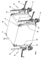
- Fig. 1 shows a formed in the present case as a cuboid cuboid transport body 10, which is provided in its corners with corner fasteners 11, which serve to connect container lifting and transport means 12.
- the container lifting and Transportcin therapiesen 12 are connected via a Tragausleger Rhein 13 with two Eckbefest Trenten 11 at a high edge 14 of the transport body 10.
- the support boom devices 13 are each connected to a Zahnstangenhub issued 15 connected, the actuated via a crank mechanism 16 allows a lifting movement of the transport body 10.
- the Zahnstangenhub respondeden 15 are provided at its lower end with a mountable wheel device 17.
- the wheel device 17 has a wheel axle 18 which is arranged to receive a wheel 19 in a steering wheel 20.
- the axle stool 20 is substantially U-shaped with a Achsschemelbasis 21 and two laterally attached thereto Achsschemelwangen 22, 23, which are each triangular in shape.
- Achsschemelbasis 21 Above the Achsschemelbasis 21 is a support bracket 24 which is provided with a here as a king pin 25 designated Einsteckzapfen serving as a coupling element.
- the kingpin 25 is provided at its the axle stool 20 facing the end with a connecting pin 29 ( Fig. 6 ), which serves to connect the support bracket 24 to the axle stool 20.
- the wheel assembly 17 is introduced with the king pin 25 in a formed on the lower end cross section of Zahnstangenhub issued 15 receiving plate 61 and secured with a locking pin 26 which engages in the securing position transverse to a kingpin axis 27 extending into an annular groove 28 of the kingpin 25.
- the kingpin 25 of the wheel device 17 can also be provided with an adapter, not shown here, by means of which the wheel device 17 can be attached directly to the lower corner fasteners 11 of the transport body 10.
- Fig. 2 As further out Fig. 2 can be seen, the kingpin axis 27 to form a wake N a corresponding distance to the wheel axle 18.
- a damping device 30 is provided, which in the present case has two damper assemblies 31, 32, which are each arranged in spaced from the wheel axle 18 end portions of the Achsschemelbasis 21 and the support bracket 24.
- each damper assembly 31 and 32 respectively comprises two damper elements 33 and 34, which are made of a damping rubber.
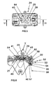
- the damper 30 facing the underside of the support bracket 24 and the damper 30 facing top of the Achsschemelbasis 21 are formed so that in the defined by the assembly of the support bracket 24 and the Achsschemels 20 relative arrangement between the underside of the support bracket 24 and the top of the Achsschemelbasis 21st four damper chambers 35, 36, 37 and 38 are formed, which each serve to receive a damper element 33 and 34, respectively.
- the here cylindrically shaped damper elements 33 and 34 are biased by acting in the connecting pin 29 between the support bracket 24 and the axle frame 20 tensile stress.
- the kingpin 25 which serves as a coupling element for connection to the Zahnstangenhub issued 15 of the container lifting and transporting device 12 and on the other hand with its connecting pin 29 for connecting the support bracket 24 with the Achsschemel 20, via a mounting flange 39 with a top 40th the support bracket 24 connected.
- the opposite of the mounting flange 39 to a coupling part 62 of the kingpin 25 in the direction of the kingpin axis 27 away extending connecting pin 29 passes through a Insertion opening 41 of the support bracket 24 and engages with its free connection end 42 in a coaxial with the insertion opening 41 of the support bracket 24 aligned through hole 43 in the Achsschemelbasis 21 a.
- the support bracket 24 is provided with a flip-over latch 64, which allows pivotal locking of the kingpin 25 by a stop against the Zahnstangenhub issued 15, so that the direction of the caster N is locked and defined.
- the connecting end 42 of the connecting pin 29 is provided with a washer 46 engaging behind an opening edge 45 of the through-opening 43, such that in a screwing-in process for producing the screw connection 44 in the damping chambers 35 to 38 (FIG. Fig. 2, 3 and 4 ) between the underside of the support bracket 24 and the top of the Achsschemelbasis 21 arranged damper elements 33 and 34 a compressive force is exerted, which has the above-mentioned bias of the damper elements 33, 34 result.
- the through hole 43 is provided in the Achsschemelbasis 21 with respect to the diameter of the connecting pin 29 with a considerable excess r, so that an annular gap 48 is formed between the connecting pin 29 and the opening edge 45 of the through hole 43, in the present case a elastic damping ring 47 is inserted.
- a synopsis of Figures 2 As if from a synopsis of Figures 2 .
- the disc 46 is provided in its connection region to the connecting pin 29 with a dome portion 49 which engages in a formed as Kalottenam 50 front end cross-section of the connecting pin 29. This makes it possible that as a result of extreme shock or braking loads acting on the screw 44, relative displacements between the connecting pin 29 and the disc 46 are made possible in a Kalottenebene, so that undesirable permanent deformation can be prevented.
- the wheel device 17 is provided with an eccentric brake 52, which causes when gripping a brake lever 53 about an eccentric axis 54, a clamping of an eccentric 55 against a wheel circumference 56.
- an eccentric brake 52 which causes when gripping a brake lever 53 about an eccentric axis 54, a clamping of an eccentric 55 against a wheel circumference 56.
- the support bracket 24 is provided with a plurality of drawbars 63, which is independent of the respective positioning of the wheel 17 a Allow connection with the drawbar device.
- a correspondingly formed drawbar device directly with axle nuts 59 of the wheel axle 18.
Landscapes
- Engineering & Computer Science (AREA)
- Mechanical Engineering (AREA)
- Chemical & Material Sciences (AREA)
- Combustion & Propulsion (AREA)
- Transportation (AREA)
- Handcart (AREA)
- Vehicle Body Suspensions (AREA)
- Forklifts And Lifting Vehicles (AREA)
Description
Die vorliegende Erfindung betrifft eine anbaubare Radeinrichtung zum Anschluss an einen Transportkörper, insbesondere für eine Container-Hub- und Transporteinrichtung, gemäß dem Oberbegriff des Anspruchs 1.The present invention relates to an attachable wheel device for connection to a transport body, in particular for a container lifting and transport device, according to the preamble of claim 1.
Anbaubare Radeinrichtungen zum Anschluss an einen Transportkörper, wie beispielsweise einen Container oder dergleichen, werden regelmäßig für einen kurzzeitigen Transporteinsatz verwendet, wenn es beispielsweise darum geht, einen Container oder dergleichen zu verladen oder über eine lediglich kurze Distanz in seiner Position zu verändern. Für den Transport über längere Strecken werden Container auf eine Ladeplattform eines Fahrzeuges, wie beispielsweise eines Lastkraftwagens oder eines Güterzugs verlastet. Aus diesem lediglich also eher vorübergehenden Einsatz derartiger Radeinrichtungen ergeben sich ganz spezifische Anforderungen, die zum einen die Schwerlastfähigkeit während des Transporteinsatzes und zum anderen die Eignung derartiger Radeinrichrungen betreffen, in der Zeit, in der sie nicht benötigt werden, möglichst raumsparend in einer Verlastepositon am Container zu verbleiben. Darüber hinaus müssen derartige Radeinrichtungen auch für den Einsatz unter erschwerten Verladebedingungen, in denen beispielsweise Rampen oder Fahrwegunebenheiten überwunden werden müssen, geeignet sein.Mountable wheel means for connection to a transport body, such as a container or the like, are regularly used for a short-term transport application, when it comes, for example, to load a container or the like or to change over its position only a short distance. For transport over longer distances containers are loaded onto a loading platform of a vehicle, such as a truck or a freight train. For this only rather temporary use of such wheel devices arise very specific requirements, on the one hand, the heavy load capacity during the Transport use and on the other hand, the suitability of such Radeinrichrungen concern, in the time they are not needed, as possible to save space in a Verlastepositon the container. In addition, such wheel devices must also be suitable for use under difficult loading conditions in which, for example, ramps or bumps in the road must be overcome.
Aus der
Bei der bekannten Radeinrichtung ist eine Verbindung zwischen der Tragkonsole und dem Achsschemel dadurch realisiert, dass die zwischenliegend angeordnete Dämpfungseinrichtung jeweils auf eine Kontaktfläche des Achsschemels und der Tragkonsole aufvulkanisiert ist.In the known wheel device, a connection between the support bracket and the axle stool is realized in that the interposed damping device is vulcanized in each case on a contact surface of the axle stool and the support bracket.
Aus der
Die
Aus der
Eine vergleichbare Ausbildung einer Radeinrichtung ist auch der
Ausgehend vom Stand der Technik liegt der vorliegenden Erfindung die Aufgabe zugrunde, eine Radeinrichtung mit zwischen der Tragkonsole und dem Achsschemel angeordneter Dämpfungseinrichtung vorzuschlagen, die einen vereinfachten mechanischen Anschluss der Dämpfungseinrichtung ermöglicht.Starting from the prior art, the present invention seeks to propose a wheel device with arranged between the support bracket and the steering rack damping device, which allows a simplified mechanical connection of the damping device.
Diese Aufgabe wird durch eine Radeinrichtung mit den Merkmalen des Anspruchs 1 gelöst.This object is achieved by a wheel device with the features of claim 1.
Die erfindungsgemäße Radeinrichtung weist einen gabelförmig ausgebildeten Achsschcmel zur Aufnahme einer Radachse, eines in den Achsschemel eingesetzten Laufrades sowie eine Tragkonsole, die zur Aufnahme eines Kupplungselements der Radeinrichtung zum Anschluss an den Transportkörper und zur Verbindung mit dem Achsschemel dient, auf. Zwischen der Tragkonsole und dem Achsschemel ist die erfindungsgemäße Radeinrichtung mit einer Dämpfungseinrichtung versehen.The wheel device according to the invention has a fork-shaped Achsschcmel for receiving a wheel axle, an impeller inserted into the steering rack and a support bracket, which serves to receive a coupling element of the wheel device for connection to the transport body and for connection to the axle stool on. Between the support bracket and the axle stool the wheel device according to the invention is provided with a damping device.
Die Aufnahme der Radachse im gabelförmig ausgebildeten Achsschemel und die Verbindung des Achsschemels mit einer die Last in die Radeinrichtung einleitenden Tragkonsole ermöglicht eine in besonderem Maße schwerlastfähige Ausführung der Radeinrichtung. Durch die Anordnung der Dämpfungseinrichtung zwischen dem Achsschemel und der Tragkonsole wird eine möglichst direkte Dämpfung bei gleichzeitig besonders raumsparender Anordnung der Dämpfungseinrichtung ermöglicht, die im Ergebnis zu einer besonders schmalen Ausgestaltung der Radeinrichtung führt.The inclusion of the wheel axle in the fork-shaped axle stool and the connection of the axle stool with a load in the wheel device Introducing support bracket allows a particularly heavy-load version of the wheel device. Due to the arrangement of the damping device between the axle stanchion and the support bracket as direct as possible damping is possible at the same time particularly space-saving arrangement of the damping device, which results in a particularly narrow design of the wheel assembly.
Bei der erfindungsgemäßen Radeinrichtung dient das Kupplungselement neben dem Anschluss an den Transportkörper auch zur Verbindung des Achsschemels mit der Tragkonsole. Aufgrund dieser Mehrfachfunktion des Kupplungselements ist es möglich, mit einer geringen Teileanzahl beim Aufbau der Radeinrichtung auszukommen, so dass eine insgesamt kompakte Ausbildung die Folge ist.In the wheel device according to the invention, the coupling element in addition to the connection to the transport body also serves to connect the axle frame with the support bracket. Due to this multiple function of the coupling element, it is possible to make do with a small number of parts in the construction of the wheel device, so that an overall compact design is the result.
Bei der erfindungsgemäßen Radeinrichtung umfasst die Dämpfungseinrichtung zumindest zwei Dämpferanordnungen, die mit Abstand zum Kupplungselement zu beiden Seiten der Radachse angeordnet sind, so dass eine in Fahrtrichtung breite Dämpfungsbasis ermöglicht wird, die die Dämpfungswirkung beim Überfahren von Hindernissen verstärkt.In the wheel device according to the invention, the damping device comprises at least two damper assemblies, which are arranged at a distance to the coupling element on both sides of the wheel axle, so that a broad in the direction of travel damping base is made possible, which enhances the damping effect when driving over obstacles.
Darüber hinaus sind bei der erfindungsgemäßen Radeinrichtung die Dämpferanordnungen durch eine im Kupplungselement zwischen der Tragkonsole und dem Achsschemel wirkend Zugspannung vorgespannt.In addition, in the wheel device according to the invention, the damper assemblies are biased by acting in the coupling element between the support bracket and the steering rack tensile stress.
Wenn darüber hinaus die Dämpferanordnungen jeweils zwei Dämpferelemente umfassen, die mit Abstand in einer Richtung parallel zur Radachse voneinander angeordnet sind, werden auch besonders gute Dämpfungseigenschaften bei quer zur Fahrtrichtung auf die Radeinrichtung bzw. einen mit der Radeinrichtung verbundenen Transportkörper einwirkenden Stoßbelastungen möglich.Moreover, if the damper assemblies each comprise two damper elements spaced apart in a direction parallel to the wheel axis, particularly good damping properties are also possible with transient loads acting transversely to the direction of travel on the wheel device or a transport body connected to the wheel device.
Ein besonders einfacher und raumsparender Aufbau der Dämpferelemente wird möglich, wenn die Dämpferelemente als Dämpfungskörper, beispielsweise als Gummidämpfer, ausgebildet sind.A particularly simple and space-saving design of the damper elements is possible when the damper elements are designed as damping body, for example as a rubber damper.
Eine besondere Richtungsstabilität einer lenkbar ausgebildeten Radeinrichtung wird möglich, wenn das Kupplungselement mit seitlichem Abstand zur Radachse angeordnet ist, so dass ein entsprechender Nachlauf an der Radeinrichtung realisiert ist. Eine aus dem Radlauf resultierende Asymmetrie der Anordnung der Dämpferelemente lässt sich besonders vorteilhaft durch eine entsprechende Auswahl bzw. Einstellung der spezifischen Dämpfungswerte des für die Dämpferelemente ausgewählten Materials, also beispielsweise der Shorehärte von Gummi, berücksichtigen.A particular directional stability of a steerable trained wheel device is possible when the coupling element is arranged at a lateral distance from the wheel axle, so that a corresponding overrun of the wheel device is realized. An asymmetry of the arrangement of the damping elements resulting from the wheel arch can be considered particularly advantageously by a corresponding selection or setting of the specific damping values of the material selected for the damping elements, for example the Shore hardness of rubber.
Besonders vorteilhaft zur Dämpfung von Anfahr- oder Bremsstoßbclastungen ist es, wenn das Kupplungselement zur Verbindung mit dem Achsschemel einen Verbindungszapfen aufweist, der bei radial zwischenliegender Anordnung eines Dämpfungselements in einer Verbindungsöffnung des Achsschemels eingesetzt ist.It is particularly advantageous for damping start-up or Bremsstoßbclastungen when the coupling element for connection to the axle stool has a connecting pin which is inserted in a radially intermediate arrangement of a damping element in a connecting opening of the axle stool.
Zur axialen Vorspannung der zwischen dem Achsschemel und der Tragkonsole angeordneten Dämpferelemente kann der Verbindungszapfen des Kupplungselements über eine die Verbindungsöffnung des Achsschemels hintergreifende Scheibe mit dem Achsschemel verbunden sein.For axial prestressing of the damping elements arranged between the axle stool and the support bracket, the connecting pin of the coupling element can be connected to the axle stool via a disk engaging behind the connecting opening of the axle stool.
Wenn die Scheibe zur Verbindung mit dem Verbindungszapfen einen Kalottenteil aufweist, der in eine stirnseitig am Verbindungszapfen ausgebildete Kalottenaufnahme eingreift, sind relative Kippbewegungen des Laufrads bzw. der Radachse quer zur Fahrrichtung möglich, ohne dass es zu unerwünscht bleibenden Verformungen an der Radeinrichtung kommen kann.If the disc for connection to the connecting pin has a dome part, which engages in a frontally formed on the connecting pin Kalottenaufnahme, relative tilting movements of the impeller or the wheel axis transverse to the direction of travel are possible without it can lead to undesirable deformation of the wheel assembly.
Besonders vorteilhaft für eine schnelle und sichere Ankupplung der Radeinrichtung an den Transportkörper oder dergleichen ist es, wenn das Kupplungselement als Einsteckzapfen ausgebildet ist.Particularly advantageous for a quick and secure coupling of the wheel device to the transport body or the like, it is when the coupling element is designed as a Einsteckzapfen.
Nachfolgend wird eine bevorzugte Ausführungsform der Radeinrichtung anhand der Zeichnung näher erläutert.Hereinafter, a preferred embodiment of the wheel device is explained in detail with reference to the drawing.
Es zeigen:
- Fig. 1
- eine Mehrzahl von in Eckbereichen eines Transportkörpers angeordneten Radeinrichtungen;
- Fig. 2
- eine Radeinrichtung in Seitenansicht;
- Fig. 3
- die in
Fig. 2 dargestellte Radeinrichtung in einer Ansicht gemäß dem Pfeil III; - Fig. 4
- die in
Fig. 2 dargestellte Radeinrichtung in einer Ansicht gemäß dem Pfeil IV; - Fig. 5
- eine Draufsicht der in
Fig. 2 dargestellten Radeinrichtung; - Fig. 6
- eine Teilschnittdarstellung der in
Fig. 5 dargestellten Radeinrichtung gemäß Schnittlinienverlauf VI-VI; - Fig. 7
- eine vergrößerte Darstellung des in
Fig. 6 mit X gekennzeichneten Bereichs.
- Fig. 1
- a plurality of wheel means arranged in corner regions of a transport body;
- Fig. 2
- a wheel device in side view;
- Fig. 3
- in the
Fig. 2 shown wheel device in a view according to the arrow III; - Fig. 4
- in the
Fig. 2 illustrated wheel device in a view according to the arrow IV; - Fig . 5
- a top view of the
Fig . 2 illustrated wheel device; - Fig. 6
- a partial sectional view of in
Fig. 5 shown wheel device according to section line VI-VI; - Fig. 7
- an enlarged view of the in
Fig. 6 X marked area.
Wie sich aus einer Zusammenschau der
Zur Verbindung mit der Zahnstangenhubeinrichtung 15 wird, wie
Alternativ kann der Königszapfen 25 der Radeinrichtung 17 auch mit einem hier nicht näher dargestellten Adapter versehen werden, mittels dem die Radeinrichtung 17 direkt an den unteren Eckbefestigungen 11 des Transportkörpers 10 befestigt werden kann.Alternatively, the
Wie ferner aus
Zwischen der Tragkonsole 24 und dem Achsschemel 20 bzw. der Achsschemelbasis 21 ist eine Dämpfungseinrichtung 30 vorgesehen, die im vorliegenden Fall zwei Dämpferanordnungen 31, 32 aufweist, die jeweils in von der Radachse 18 beabstandeten Endbereichen der Achsschemelbasis 21 bzw. der Tragkonsole 24 angeordnet sind.Between the
Wie aus den
Wie aus einer Zusammenschau der
Wie eine Zusammenschau der
Wie insbesondere aus der vergrößerten Detaildarstellung des in
Wie ferner aus
Wie ferner aus
Wie aus einer Zusammenschau der
Zur Verbindung der bereits vorstehend erwähnten, hier nicht näher dargestellten Deichseleinrichtung mit einer Radeinrichtung 17 bzw. zwei auf einer Seite des Transportkörpers 10 angeordneten Radeinrichtungen 17 ist die Tragkonsole 24 mit einer Mehrzahl von Zugösen 63 versehen, die unabhängig von der jeweiligen Positionierung der Radeinrichtung 17 eine Verbindung mit der Deichseleinrichtung ermöglichen. Alternativ ist es auch möglich, eine entsprechend ausgebildete Deichseleinrichtung unmittelbar mit Achsmuttern 59 der Radachse 18 zu verbinden.To connect the already mentioned above, not shown drawbar device with a
Claims (8)
- A mountable wheel assembly (17) for attachment to a transporting body (10), in particular for a container, lifting gear and transport assembly, comprising a fork-shaped axle bolster (20) for accommodating the axle (18) of a running wheel (19) fitted in the axle bolster (20), also comprising a support bracket (24) that serves for accommodating a coupling element (25) of the wheel assembly for attachment to the transporting body and for connection to the axle bolster, as well as a damping device (30) acting between the support bracket and the axle bolster,
characterized in that
the coupling element (25) serves for connecting the axle bolster (20) to the support bracket (24), and that the damping device (30) comprises a minimum of two shock absorbers (31, 32), which are arranged on both sides of the wheel axle (18) spaced apart from the coupling element (25) and which are pre-stressed by tensile stress acting in the coupling element (25) between the support bracket (24) and the axle bolster (20). - A wheel assembly according to claim 1,
characterized in that
the shock absorbers (31, 32) each comprise two damping elements (33, 34) which are arranged spaced apart from each other in one direction parallel to the wheel axle (18). - A wheel assembly according to claim 2,
characterized in that
the damping elements (33, 34) are designed as damping bodies. - A wheel assembly according to one of the preceding claims,
characterized in that
the coupling element (25) is arranged at a lateral distance to the wheel axle (18). - A wheel assembly according to one of the preceding claims,
characterized in that
the coupling element (25) for the connection to the axle bolster (20) features an assembly pin (29) which, with a radially interspersed damping element (33, 34), is inserted in a link opening (43) of the axle bolster. - A wheel assembly according to claim 5,
characterized in that
for the purpose of axial pre-stressing of the damping elements (33, 34) arranged between the axle bolster (20) and the support bracket (24), the assembly pin (29) of the coupling element (25) is connected to the axle bolster by a disk (46) engaging from behind in the link opening (43) of the axle bolster. - A wheel assembly according to claim 6,
characterized in that
the disk (46) for connection to the assembly pin (29) features a calotte part (49) that engages in a calotte reception (50) formed on the front face of the assembly pin (29). - A wheel assembly according to one of the preceding claims,
characterized in that
the coupling element (25) is designed as an plug-in pin.
Applications Claiming Priority (2)
| Application Number | Priority Date | Filing Date | Title |
|---|---|---|---|
| DE10361126 | 2002-12-12 | ||
| DE2003161126 DE10361126B4 (en) | 2003-12-22 | 2003-12-22 | Mountable wheel device |
Publications (3)
| Publication Number | Publication Date |
|---|---|
| EP1547900A2 EP1547900A2 (en) | 2005-06-29 |
| EP1547900A3 EP1547900A3 (en) | 2007-06-20 |
| EP1547900B1 true EP1547900B1 (en) | 2009-01-21 |
Family
ID=34530394
Family Applications (1)
| Application Number | Title | Priority Date | Filing Date |
|---|---|---|---|
| EP20040003860 Expired - Lifetime EP1547900B1 (en) | 2003-12-22 | 2004-02-20 | Mountable wheel arrangement |
Country Status (2)
| Country | Link |
|---|---|
| EP (1) | EP1547900B1 (en) |
| DE (2) | DE10361126B4 (en) |
Families Citing this family (4)
| Publication number | Priority date | Publication date | Assignee | Title |
|---|---|---|---|---|
| DE202010014784U1 (en) * | 2010-10-29 | 2012-01-30 | Willi Kapfer | Transport device for containers |
| CN106000176A (en) * | 2016-06-01 | 2016-10-12 | 李明科 | Movable industrial stirrer |
| CN106114585B (en) * | 2016-08-18 | 2018-08-14 | 郭冬青 | A kind of mosaic tiles transport device |
| WO2021011969A1 (en) * | 2019-07-17 | 2021-01-21 | Van Chanh NGUYEN | Wheel structure for 360-degree rotating building in water tank and 360-degree rotating building in water tank |
Family Cites Families (6)
| Publication number | Priority date | Publication date | Assignee | Title |
|---|---|---|---|---|
| US2647277A (en) | 1949-01-03 | 1953-08-04 | Roll Rite Corp | Wheel and mounting assembly |
| US3286298A (en) * | 1964-12-08 | 1966-11-22 | William J Veary | Caster assembly |
| DE2833330C2 (en) * | 1978-07-29 | 1982-12-23 | Paul Vom Stein & Co, 5632 Wermelskirchen | Castor for trolleys, apparatus, furniture or the like. |
| DE9301694U1 (en) | 1993-02-08 | 1993-03-25 | Acla-Werke GmbH, 5000 Köln | Castor |
| DE29501456U1 (en) * | 1994-02-03 | 1995-03-23 | Acla-Werke GmbH, 51065 Köln | Swivel castor |
| GB2396100A (en) * | 2002-12-10 | 2004-06-16 | Te-Hsin Hsiao | A castor wheel assembly having a spring shock absorber |
-
2003
- 2003-12-22 DE DE2003161126 patent/DE10361126B4/en not_active Expired - Fee Related
-
2004
- 2004-02-20 DE DE200450008907 patent/DE502004008907D1/en not_active Expired - Lifetime
- 2004-02-20 EP EP20040003860 patent/EP1547900B1/en not_active Expired - Lifetime
Also Published As
| Publication number | Publication date |
|---|---|
| EP1547900A2 (en) | 2005-06-29 |
| DE10361126A1 (en) | 2005-07-21 |
| EP1547900A3 (en) | 2007-06-20 |
| DE502004008907D1 (en) | 2009-03-12 |
| DE10361126B4 (en) | 2006-06-01 |
Similar Documents
| Publication | Publication Date | Title |
|---|---|---|
| DE102014220291A1 (en) | Storage for a driver's cab of a vehicle | |
| EP1088687B1 (en) | Connection between a vehicle wheel axle and an arm bearing the wheel axle | |
| DE3232410A1 (en) | WHEEL SUSPENSION FOR VEHICLES | |
| DE60004214T2 (en) | SELF-DRIVING AXLE | |
| EP1547900B1 (en) | Mountable wheel arrangement | |
| EP2830917B1 (en) | Height-adjustable support device for semi-trailers or the like | |
| EP1107891B1 (en) | Support foot | |
| DE202011104769U1 (en) | One-axle trailer for a motor vehicle | |
| DE102017218796A1 (en) | Axle | |
| DE19532883C2 (en) | Safety steering column for a motor vehicle | |
| DE10202778B4 (en) | Brake support assembly | |
| EP0501150B1 (en) | Motor vehicle with a towing device | |
| EP0622254B1 (en) | Suspension arm for axles of industrial vehicles | |
| DE20218453U1 (en) | Steerable axle has stabilizing device constructed in articulated connection between axle body and respective steering fork, and has at least one bearing element of elastic material encompassing pivot of articulated connection | |
| EP0600500A1 (en) | Vehicle trailer coupling arrangement | |
| DE102018109814B4 (en) | Drawbar and vehicle trailer | |
| DE2815503C2 (en) | Drawbar mounting for trailers of motor vehicles | |
| EP1281568B1 (en) | Lift platform for attaching on a vehicle | |
| DE8809320U1 (en) | Device for holding or securing objects | |
| DE202021102290U1 (en) | Support device for a vehicle | |
| DE202023105183U1 (en) | Fastening arrangement for fastening at least one air spring element to a vehicle axle | |
| EP1389561A2 (en) | Displacement and locking device for two assemblies and transport vehicle with such a device | |
| DE102007011720A1 (en) | Bolt for a band arrangement for fixing a container to a longitudinal support of a commercial vehicle comprises a insertion bevel by which the bolt can be inserted into the corresponding opening of a console | |
| DD270888A1 (en) | TAILGATE FASTENING FOR RAIL TRANSPORT VEHICLES | |
| DE202008015664U1 (en) | Front-axle runner for receiving semitrailers |
Legal Events
| Date | Code | Title | Description |
|---|---|---|---|
| PUAI | Public reference made under article 153(3) epc to a published international application that has entered the european phase |
Free format text: ORIGINAL CODE: 0009012 |
|
| AK | Designated contracting states |
Kind code of ref document: A2 Designated state(s): AT BE BG CH CY CZ DE DK EE ES FI FR GB GR HU IE IT LI LU MC NL PT RO SE SI SK TR |
|
| AX | Request for extension of the european patent |
Extension state: AL LT LV MK |
|
| PUAL | Search report despatched |
Free format text: ORIGINAL CODE: 0009013 |
|
| AK | Designated contracting states |
Kind code of ref document: A3 Designated state(s): AT BE BG CH CY CZ DE DK EE ES FI FR GB GR HU IE IT LI LU MC NL PT RO SE SI SK TR |
|
| AX | Request for extension of the european patent |
Extension state: AL LT LV MK |
|
| RIC1 | Information provided on ipc code assigned before grant |
Ipc: B62B 5/00 20060101AFI20041025BHEP Ipc: B60B 33/04 20060101ALI20070511BHEP |
|
| 17P | Request for examination filed |
Effective date: 20070726 |
|
| 17Q | First examination report despatched |
Effective date: 20071123 |
|
| AKX | Designation fees paid |
Designated state(s): DE FR GB |
|
| GRAP | Despatch of communication of intention to grant a patent |
Free format text: ORIGINAL CODE: EPIDOSNIGR1 |
|
| GRAS | Grant fee paid |
Free format text: ORIGINAL CODE: EPIDOSNIGR3 |
|
| GRAA | (expected) grant |
Free format text: ORIGINAL CODE: 0009210 |
|
| AK | Designated contracting states |
Kind code of ref document: B1 Designated state(s): DE FR GB |
|
| REG | Reference to a national code |
Ref country code: GB Ref legal event code: FG4D Free format text: NOT ENGLISH |
|
| REF | Corresponds to: |
Ref document number: 502004008907 Country of ref document: DE Date of ref document: 20090312 Kind code of ref document: P |
|
| PLBE | No opposition filed within time limit |
Free format text: ORIGINAL CODE: 0009261 |
|
| STAA | Information on the status of an ep patent application or granted ep patent |
Free format text: STATUS: NO OPPOSITION FILED WITHIN TIME LIMIT |
|
| 26N | No opposition filed |
Effective date: 20091022 |
|
| PGFP | Annual fee paid to national office [announced via postgrant information from national office to epo] |
Ref country code: FR Payment date: 20140218 Year of fee payment: 11 |
|
| PGFP | Annual fee paid to national office [announced via postgrant information from national office to epo] |
Ref country code: GB Payment date: 20140220 Year of fee payment: 11 |
|
| PGFP | Annual fee paid to national office [announced via postgrant information from national office to epo] |
Ref country code: DE Payment date: 20140424 Year of fee payment: 11 |
|
| REG | Reference to a national code |
Ref country code: DE Ref legal event code: R119 Ref document number: 502004008907 Country of ref document: DE |
|
| GBPC | Gb: european patent ceased through non-payment of renewal fee |
Effective date: 20150220 |
|
| REG | Reference to a national code |
Ref country code: FR Ref legal event code: ST Effective date: 20151030 |
|
| PG25 | Lapsed in a contracting state [announced via postgrant information from national office to epo] |
Ref country code: GB Free format text: LAPSE BECAUSE OF NON-PAYMENT OF DUE FEES Effective date: 20150220 Ref country code: DE Free format text: LAPSE BECAUSE OF NON-PAYMENT OF DUE FEES Effective date: 20150901 |
|
| PG25 | Lapsed in a contracting state [announced via postgrant information from national office to epo] |
Ref country code: FR Free format text: LAPSE BECAUSE OF NON-PAYMENT OF DUE FEES Effective date: 20150302 |