EP1547894A1 - Track guided vehicle system - Google Patents
Track guided vehicle system Download PDFInfo
- Publication number
- EP1547894A1 EP1547894A1 EP04027684A EP04027684A EP1547894A1 EP 1547894 A1 EP1547894 A1 EP 1547894A1 EP 04027684 A EP04027684 A EP 04027684A EP 04027684 A EP04027684 A EP 04027684A EP 1547894 A1 EP1547894 A1 EP 1547894A1
- Authority
- EP
- European Patent Office
- Prior art keywords
- branching
- rollers
- guide
- track
- guided vehicle
- Prior art date
- Legal status (The legal status is an assumption and is not a legal conclusion. Google has not performed a legal analysis and makes no representation as to the accuracy of the status listed.)
- Granted
Links
Images


Classifications
-
- B—PERFORMING OPERATIONS; TRANSPORTING
- B61—RAILWAYS
- B61B—RAILWAY SYSTEMS; EQUIPMENT THEREFOR NOT OTHERWISE PROVIDED FOR
- B61B13/00—Other railway systems
- B61B13/04—Monorail systems
Definitions
- the present invention relates to a system using a track guided vehicle that runs along a running track, and in particular, to branching control of a track guided vehicle.
- a track guided vehicle system uses track guided vehicles to transport articles in a clean room, in a general factory, hospital, or library, or outdoors. Branching is required to provided a complicated layout of running tracks.
- the Unexamined Japanese Patent Application Publication (Tokkai) No. 2003-212112 discloses branching control of a track guided vehicle system.
- a branching portion of the running track is provided with paired guide grooves for rectilinear progression and for branching.
- a track guided vehicle is provided with paired branching rollers corresponding to the guide grooves. The branching rollers can be extended to and withdrawn from a position where they are guided through the guide grooves and a position where they are free.
- An additional object of the invention in Claim 2 is to allow the height position of branching rollers to be reliably controlled, thus ensuring that rectilinear progression and branching can be controlled.
- An additional object of the invention in Claims 3 and 4 is to prevent elevation and lowering of the branching rollers from interfering with guide rollers to eliminate the need to reduce speed in front of a branching portion and to allow a track guided vehicle to run stably through the branching portion at high speed either for rectilinear progression or for branching.
- a track guided vehicle system In a track guided vehicle system according to the present invention, guide tracks projecting in a vertical direction are provided in a right and left of a running track and left and right guide rollers are provided on a track guided vehicle and guided using inner surfaces of the left and right guide tracks.
- Branching rollers each comprising elevating and lowering means are provided in the right and left of the track guided vehicle and outside the right and left guide tracks.
- cam plates that can be rotatively moved are each provided with a spiral cam used to elevate and lower the corresponding one of the branching rollers via a cam follower. Further, each of the spiral cams is provided with at least two areas corresponding to positions where the corresponding one of the branching rollers is stopped, the areas having almost fixed radii of curvature from a center of rotative movement of the cam plate.
- the branching rollers are elevated or lowered in an area which is provided in a rectilinear progression section of the guide tracks and in which a gap is created between each of the branching rollers and the corresponding one of the guide tracks. Further, in a branching portion of the guide tracks, both the right or left branching rollers and the right or left guide rollers are abutted against the corresponding guide track. Moreover, the gap is formed by making the width of the guide track in the branching portion larger than that in the rectilinear progression section.
- whether the track guided vehicle runs straight or shifts to a branch course can be controlled by contacting one of the branching rollers with the outer surface of the corresponding guide track, which guides the guide rollers in the section (rectilinear progression section) different from the branching portion.
- the cam follower when the cam plate is rotatively moved, the cam follower, for example, reciprocates in accordance with the spiral cam. This elevates or lowers the corresponding branching roller.
- the spiral cam is provided with the areas having the almost fixed radii of curvature from the center of rotative movement of the cam plate.
- the cam follower lies in one of these areas, the cam plate is stopped.
- the height position of the branching roller measured when its elevation or lowering is stopped is almost fixed in spite of a small variation in the stopped position of the cam plate. Therefore, the height position of the branching roller can be precisely controlled.
- branching or rectilinear progression is selected by elevating or lowering the branching rollers in the area in the rectilinear progression section in which a gap is created between each branching roller and the corresponding guide track.
- the elevation and lowering of the branching rollers does not interfere with the guide tracks.
- the track guided vehicle is supported by pressing the right or left branching rollers and right or left guide rollers against the outer and inner surfaces of the corresponding guide track so as to create substantially no gaps. Accordingly, even where running wheels are separated from a floor or ground surface, the track guided vehicle is not shaken or impacted. Therefore, the track guided vehicle can run at high speed regardless of whether it runs straight through or shifts to a branch line in the branching portion.
- each of the guide tracks is wider in the branching portion so as to be tightly sandwiched between the corresponding branching rollers and guide rollers.
- each of the guide tracks is narrower in the rectilinear progression section so as to create a gap between the guide track and the corresponding branching rollers. In this manner, varying the width of the guide track enables each of the branching rollers to contact with the guide track or a gap to be created between them.
- 2 is an overhead traveling vehicle
- 4, 5 are front and rear paired bogies.
- 6 is an overhead traveling vehicle main body.
- the overhead traveling vehicle main body 6 is supported at the bottom of the bogies 4, 5 using a front and rear shafts 8, 8.
- a frame 10 is provided so as to connect the front and rear shafts 8, 8 together.
- a drive wheel 14 is driven via a running motor 12 on the frame 10. The drive wheel 14 is pressed by urging means (not shown in the drawing) against a bottom surface of an upper part of a running track to allow the overhead traveling vehicle 2 to run.
- Each of the front and rear bogies 4, 5 is provided with free running wheels 16, 18 and runs using a top surface of a lower part of the running track as a tread.
- a total of four guide rollers 20, 21 including the front and rear guide rollers, and the right and left guide rollers are provided at the top of each of the bogies 4, 5, and the guide rollers 20, 21 are guided using inner guide surfaces of a guide track.
- the guide rollers 21 are eccentric rollers and their structure is shown in Figure 3.
- the guide rollers 20 are typical free rollers.
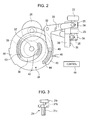
- paired branching rollers 22, 23 are provided near a central portion of each of the bogies 4, 5 and laterally outside the guide rollers 20, 21.
- the branching rollers 22, 23 are elevated and lowered using opposite phases.
- 30 is a pivoting arm and 32 is a pin acting as a pivoting center of the pivoting arm 30.
- an elevating and lowering member 34 is mounted at one end of the pivoting arm 30.
- the elevating and lowering member 34 elevates and lowers together with the branching rollers 22, 23.
- 36 is an elevating and lowering guide that guides elevating and lowering motion of the elevating and lowering member 34, and the elevating and lowering guide 36 is, for example, a linear guide.
- 35 is a slot formed in the elevating and lowering member 34 and through which a pin or the like provided at the tip of the pivoting arm 30 is slid with respect to the elevating and lowering member 34.
- a spiral cam groove 38 is formed around a rotative movement center 37 of each of the cam plates 24, 25, and a cam follower 40 provided at an end of the corresponding pivoting arm 30 is guided through the cam groove 38.
- the cams formed in the cam plates 24, 25 are not limited to groove-like ones but have only to be spiral so as to guide the cam followers. Further, the cam plates 24, 25 and the pivoting arms 30 are rotatively moved in a vertical plane to elevate and lower the branching rollers 22, 23.
- the cam groove 38 has, for example, three concentric areas having fixed radii of curvature from the rotative movement center 37.
- a low position area 42 has the smallest radius of curvature, and an intermediate position area 43 is located at a position obtained by rotatively moving the cam plates 24, 25 through, for example, 180 degrees.
- a high position area 44 is located at a position obtained by further rotatively moving the cam plates 24, 25 through, for example, 180 degrees.
- Each of the low position area 42 and high position area 44 is present within a rotation angle (phase) of 45 degrees in each of the cam plates 24, 25.
- the cam groove 38 is concentric and it is concentric within a phase of, for example, 90 degrees in the intermediate position area 43.
- the cam plates 24, 25 can be rotatively moved through a little more than 360 degrees.
- Detected portions 45, 46 are provided on each of the cam plates 24, 25 so as to project from the other portions in a radial direction.
- a phase sensor 48 detects the detected portions 45, 46, and the phase sensor 48 detects, for example, edges of the detected portions 45, 46. Each edge is located at an almost central portion of the concentric part of the area 42, 43, 44. That is, the phase sensor 48 uses the edges of the detected portions 45, 46 to detect when the cam follower 40 has reached almost the center of the area 42, 43, 44.
- the lateral paired cam plates 24, 25 are rotatively moved by the elevating and lowering motor 26, and are stopped by the brake 28.
- the layout of the cam groove 38 differs between the cam plates 24, 25 so that when one of the cam followers 40 is in the high position area 44 in the cam plate 24 side, the other cam follower 40 is in the low position area 42 in the cam plate 25 side.
- the intermediate position area 43 is set to have the same phase in the right and left cam plates 24, 25.
- a control section 49 controls the elevating and lowering motor 26, and the brake 28 in accordance with a signal from the phase sensor 48 to control the heights of the branching rollers 22, 23.
- a mechanism for elevating and lowering the branching rollers 22, 23 is arbitrary.
- Figure 3 shows an example of the guide roller 21.
- 21r is an eccentric roller consisting of a free roller.
- a shaft 21b of the eccentric roller 21r is eccentric to the axis of a mounting portion 21c. Rotating a threaded portion of the mounting portion 21c enables the distance between the lateral paired guide rollers to be adjusted at the site.
- the branching roller located closer to the eccentric rollers, for example, in this case, the branching roller 22 preferably has its lateral position freely adjusted as an eccentric roller.
- 51 is a branching portion of the running track 50
- 52 is a rectilinear progression section (this means that this section has no branch or mergence).
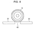
- a right and left treads 53, 53 are provided on a top surface of a lower part of the box-like running track 50 to support running wheels 16, 18.
- an opening 54 is formed between the treads 53, 53 so that the shafts 8, used to connect the bogies 4, 5 together, can pass through the opening 54.
- guide track 56 projecting downward in the vertical direction are provided on the right and left sides, respectively, of a bottom surface of an upper part of the running track 50. The width of the guide track 56 is set to vary between the rectilinear progression section 52 and the branching portion 51.
- the guide track 56 in the branching portion 51 is formed as a wider portion 58 that is wider than the guide track 56 in the rectilinear progression section 52 by, for example, about 1 mm outward in the lateral direction (wider on the side of the guide track 56 with which the branching rollers 22, 23 contact).
- a gap of, for example, about 1 mm is created between the guide track 56 and the branching rollers 22, 23.
- each eccentric guide roller 21 is used to adjust the spacing between the guide rollers 20, 21 at the time of installation or the like, the guide rollers 20, 21 are in tight contact with inner surfaces of the guide tracks 56, 56.
- running upward in Figure 4 corresponds to rectilinear progression
- running upward and rightward in Figure 4 corresponds to branching.
- the guide track 56 and its wider portion 58 are arranged so as not to create any gap between them.
- the guide track 56 and its wider portion 58 are also arranged on the right side of the opening 54 except for a cut portion 64.
- Figure 5 shows how the guide rollers 20, 21 and the branching rollers 22, 23 are positioned relative to the guide track 56 in the rectilinear progression section 52.
- An inner surface of each of the guide tracks 56, 56 constitutes a guide surface 60
- an outer surface of the guide track 56 constitutes a guide surface 61.
- the guide surface 61 is shifted outward of the guide track 56 by about 1 mm.
- the branching rollers 22, 23 are at, for example, the height of the intermediate position.
- the left and right guide rollers 20, 21 contact tightly with the left and right guide surfaces 60, 60, respectively, to guide the overhead traveling vehicle 2.
- a solid line in Figure 8 shows how the running wheels 16 and others operate when the track guided vehicle passes through the Y-shaped portion 62.
- the running wheels 16 and others sink slightly to shake the bogies 4, 5.
- the wider portion 58 is tightly sandwiched between the rollers 20, 23 or the rollers 21, 22. This prevents the bogies 4, 5 from being shaken.
- Figures 9 and 10 show operations during rectilinear progression.
- the branching rollers 23 are at the high position, while the branching rollers 22 are at the low position.
- the right-hand branching rollers 22 do not contact with the guide track 56, while the wider portion 58 of the guide track 56 is sandwiched between the left-hand branching rollers 23 and the guide rollers 20.
- the branching rollers 22, 23 are elevated or lowered in a part of the rectilinear progression section 52 which lies in front of the branching portion 51. In this case, the elevation and lowering of the branching rotters 22, 23 does not interfere with the guide track 56. Therefore, the track guided vehicle can run straight through the branching portion 51 at high speed.
- Figures 11 and 12 show the conditions during branching.
- the branching rollers 22 are at the high position.
- the wider portion 58 is sandwiched between the branching rollers 22 and the guide rollers 21.
- the left-hand branching rollers 23 are at the low position and pass below the guide track 56.
- the branching rollers 22, 23 are elevated or lowered in a part of the rectilinear progression section 52 which lies in front of the branching portion 51. Therefore, the track guided vehicle can shift to the branch line at high speed.
- the guide track 56 is narrower than the wider portion 58 all along the rectilinear progression section 52.
- the guide track 56 may be formed to be narrower only in a predetermined area in front of the branching portion 51.
- the track guided vehicle may be run upward in Figure 4.
- the branching rollers 22, 23 and others are operated as described in Figure 9.
- the branching rollers 22, 23 and others are operated as described in Figure 11.
- the branching rollers 22, 23 are switched between the three height positions.
- the branching rollers 22, 23 may be switched between two height positions for branching and rectilinear progression.
- the track guided vehicle may in principle run straight in the rectilinear progression section 52, and if the vehicle is to shift to a branch line, the branching rollers 22, 23 may be switched to the corresponding height position in front of the branching portion 51.
- the longitudinal paired guide rollers 20 and the longitudinal paired guide rollers 21 are provided on each bogie.
- Each branching roller is placed at the intermediate position of the bogie in its longitudinal direction.
- the longitudinal paired branching rollers may be provided on each bogie, with the guide rollers each provided at the intermediate position of the bogie in its longitudinal direction. In this case, the four branching rollers and the two guide rollers are provided on each bogie.
- the overhead traveling vehicle is shown in the embodiment.
- the present invention is applicable to a track guide vehicle that runs along a running track laid on the ground.
- an opening may be formed at the top of the running track, with a carriage placed over the opening.
- the guide tracks are provided on the bottom surface of the upper part of the running track and on the right and left sides, respectively, of the opening.
Abstract
Description
- The present invention relates to a system using a track guided vehicle that runs along a running track, and in particular, to branching control of a track guided vehicle.
- A track guided vehicle system uses track guided vehicles to transport articles in a clean room, in a general factory, hospital, or library, or outdoors. Branching is required to provided a complicated layout of running tracks. The Unexamined Japanese Patent Application Publication (Tokkai) No. 2003-212112 discloses branching control of a track guided vehicle system. In the Unexamined Japanese Patent Application Publication (Tokkai) No. 2003-212112, a branching portion of the running track is provided with paired guide grooves for rectilinear progression and for branching. Further, a track guided vehicle is provided with paired branching rollers corresponding to the guide grooves. The branching rollers can be extended to and withdrawn from a position where they are guided through the guide grooves and a position where they are free. Whether the track guided vehicle runs straight or shifts to a branch line is controlled by selecting the branching roller guided by the corresponding guide groove. Further, in the entire running track except for its branching portion, guide wheels are guided using a vertical portion of the running track. However, this track guided vehicle system requires the pair of guide grooves to be provided for the branching control. Consequently, the running track has a complicated shape.
- It is an object of the present invention to provide a track guided vehicle system that can use a simple configuration to determine whether the track guided vehicle runs straight or shifts to a branch line.
- An additional object of the invention in
Claim 2 is to allow the height position of branching rollers to be reliably controlled, thus ensuring that rectilinear progression and branching can be controlled. - An additional object of the invention in
Claims 3 and 4 is to prevent elevation and lowering of the branching rollers from interfering with guide rollers to eliminate the need to reduce speed in front of a branching portion and to allow a track guided vehicle to run stably through the branching portion at high speed either for rectilinear progression or for branching. - In a track guided vehicle system according to the present invention, guide tracks projecting in a vertical direction are provided in a right and left of a running track and left and right guide rollers are provided on a track guided vehicle and guided using inner surfaces of the left and right guide tracks. Branching rollers each comprising elevating and lowering means are provided in the right and left of the track guided vehicle and outside the right and left guide tracks. Thus, branching and rectilinear progression of the track guided vehicle is controlled by switching between a state where the branching rollers are elevated or lowered to guide the track guided vehicle using outer surfaces of the guide tracks and a state where the branching rollers do not contact with the outer surfaces.
- Preferably, cam plates that can be rotatively moved are each provided with a spiral cam used to elevate and lower the corresponding one of the branching rollers via a cam follower. Further, each of the spiral cams is provided with at least two areas corresponding to positions where the corresponding one of the branching rollers is stopped, the areas having almost fixed radii of curvature from a center of rotative movement of the cam plate.
- Further, preferably, the branching rollers are elevated or lowered in an area which is provided in a rectilinear progression section of the guide tracks and in which a gap is created between each of the branching rollers and the corresponding one of the guide tracks. Further, in a branching portion of the guide tracks, both the right or left branching rollers and the right or left guide rollers are abutted against the corresponding guide track. Moreover, the gap is formed by making the width of the guide track in the branching portion larger than that in the rectilinear progression section.
- In the track guided vehicle system according to the present invention, whether the track guided vehicle runs straight or shifts to a branch course can be controlled by contacting one of the branching rollers with the outer surface of the corresponding guide track, which guides the guide rollers in the section (rectilinear progression section) different from the branching portion.
- According to the aspect of the present invention in
Claim 2, when the cam plate is rotatively moved, the cam follower, for example, reciprocates in accordance with the spiral cam. This elevates or lowers the corresponding branching roller. The spiral cam is provided with the areas having the almost fixed radii of curvature from the center of rotative movement of the cam plate. When the cam follower lies in one of these areas, the cam plate is stopped. Then, the height position of the branching roller measured when its elevation or lowering is stopped is almost fixed in spite of a small variation in the stopped position of the cam plate. Therefore, the height position of the branching roller can be precisely controlled. - According to the aspect of the present invention in Claim 3, branching or rectilinear progression is selected by elevating or lowering the branching rollers in the area in the rectilinear progression section in which a gap is created between each branching roller and the corresponding guide track. Thus, the elevation and lowering of the branching rollers does not interfere with the guide tracks. This eliminates the need to decelerate the track guided vehicle in front of the branching portion. Consequently, the branching rollers can be smoothly elevated and lowered. Further, in the branching portion, the track guided vehicle is supported by pressing the right or left branching rollers and right or left guide rollers against the outer and inner surfaces of the corresponding guide track so as to create substantially no gaps. Accordingly, even where running wheels are separated from a floor or ground surface, the track guided vehicle is not shaken or impacted. Therefore, the track guided vehicle can run at high speed regardless of whether it runs straight through or shifts to a branch line in the branching portion.
- According to the aspect of the present invention in
Claim 4, each of the guide tracks is wider in the branching portion so as to be tightly sandwiched between the corresponding branching rollers and guide rollers. On the other hand, each of the guide tracks is narrower in the rectilinear progression section so as to create a gap between the guide track and the corresponding branching rollers. In this manner, varying the width of the guide track enables each of the branching rollers to contact with the guide track or a gap to be created between them. -
- Figure 1 is a plan view showing essential parts of bogies used in an embodiment and provided in the front and rear, respectively, of an overhead traveling vehicle.
- Figure 2 is a side view showing an essential part of an elevating and lowering mechanism on the overhead traveling vehicle which mechanism is used in the embodiment.
- Figure 3 is a side view of an eccentric roller used in the embodiment.
- Figure 4 is a horizontal sectional view showing a horizontal track in a branching portion, in an overhead traveling vehicle system according to the embodiment.
- Figure 5 is a diagram showing how guide rollers and branching rollers are positioned relative to a guide track in a rectilinear progression section.
- Figure 6 is a diagram showing how the guide rollers and the branching rollers are positioned relative to the guide track when the vehicle runs straight through a branching portion.
- Figure 7 is a diagram showing how the guide rollers and the branching rollers are positioned relative to the guide track when the vehicle shifts to a branch line in the branching portion.
- Figure 8 is a diagram schematically showing how running wheels pass over a cut portion of a tread.
- Figure 9 is a diagram schematically showing how the overhead traveling vehicle runs straight through the branching portion in Figure 4.
- Figure 10 is a sectional view taken along a line X-X in Figure 9 and schematically showing how the guide rollers, the branching rollers, and the running wheels are arranged in the running track during rectilinear progression.
- Figure 11 is a diagram showing how the overhead traveling vehicle shifts to a branch line in the branching portion shown in Figure 4.
- Figure 12 is a sectional view taken along a line XII-XII in Figure 11 and schematically showing how the guide rollers, the branching rollers, and the running wheels are arranged in the running track during branching.
-
- In the figures, 2 is an overhead traveling vehicle, and 4, 5 are front and rear paired bogies. 6 is an overhead traveling vehicle main body. The overhead traveling vehicle
main body 6 is supported at the bottom of thebogies rear shafts frame 10 is provided so as to connect the front andrear shafts drive wheel 14 is driven via a runningmotor 12 on theframe 10. Thedrive wheel 14 is pressed by urging means (not shown in the drawing) against a bottom surface of an upper part of a running track to allow theoverhead traveling vehicle 2 to run. - Each of the front and
rear bogies wheels guide rollers bogies guide rollers guide rollers 21 are eccentric rollers and their structure is shown in Figure 3. Theguide rollers 20 are typical free rollers. Further, paired branchingrollers bogies guide rollers rollers - 24, 25 are a right and left cam plates driven by a common elevating and lowering
motor 26 and acommon brake 28. 30 is a pivoting arm and 32 is a pin acting as a pivoting center of the pivotingarm 30. Further, an elevating and loweringmember 34 is mounted at one end of the pivotingarm 30. The elevating and loweringmember 34 elevates and lowers together with the branchingrollers member 34, and the elevating and loweringguide 36 is, for example, a linear guide. 35 is a slot formed in the elevating and loweringmember 34 and through which a pin or the like provided at the tip of the pivotingarm 30 is slid with respect to the elevating and loweringmember 34. - A
spiral cam groove 38 is formed around arotative movement center 37 of each of thecam plates cam follower 40 provided at an end of the corresponding pivotingarm 30 is guided through thecam groove 38. The cams formed in thecam plates cam plates arms 30 are rotatively moved in a vertical plane to elevate and lower the branchingrollers cam groove 38 has, for example, three concentric areas having fixed radii of curvature from therotative movement center 37. Alow position area 42 has the smallest radius of curvature, and anintermediate position area 43 is located at a position obtained by rotatively moving thecam plates high position area 44 is located at a position obtained by further rotatively moving thecam plates - Each of the
low position area 42 andhigh position area 44 is present within a rotation angle (phase) of 45 degrees in each of thecam plates cam groove 38 is concentric and it is concentric within a phase of, for example, 90 degrees in theintermediate position area 43. Thecam plates portions cam plates phase sensor 48 detects the detectedportions phase sensor 48 detects, for example, edges of the detectedportions area phase sensor 48 uses the edges of the detectedportions cam follower 40 has reached almost the center of thearea - The lateral paired
cam plates motor 26, and are stopped by thebrake 28. The layout of thecam groove 38 differs between thecam plates cam followers 40 is in thehigh position area 44 in thecam plate 24 side, theother cam follower 40 is in thelow position area 42 in thecam plate 25 side. Theintermediate position area 43 is set to have the same phase in the right and leftcam plates control section 49 controls the elevating and loweringmotor 26, and thebrake 28 in accordance with a signal from thephase sensor 48 to control the heights of the branchingrollers rollers - Figure 3 shows an example of the
guide roller 21. 21r is an eccentric roller consisting of a free roller. Ashaft 21b of theeccentric roller 21r is eccentric to the axis of a mountingportion 21c. Rotating a threaded portion of the mountingportion 21c enables the distance between the lateral paired guide rollers to be adjusted at the site. The branching roller located closer to the eccentric rollers, for example, in this case, the branchingroller 22 preferably has its lateral position freely adjusted as an eccentric roller. - With reference to Figures 4 to 12, a description will be given of the configuration of a running
track 50 and operations of the overhead traveling vehicle in the branching portion. The members of the system may be denoted by the same reference numerals as those used in Figures 1 to 3 though the numerals are not used in Figures 4 to 12. - 51 is a branching portion of the running
track treads like running track 50 to support runningwheels opening 54 is formed between thetreads shafts 8, used to connect thebogies opening 54. Furthermore,guide track 56 projecting downward in the vertical direction are provided on the right and left sides, respectively, of a bottom surface of an upper part of the runningtrack 50. The width of theguide track 56 is set to vary between therectilinear progression section 52 and the branchingportion 51. Theguide track 56 in the branchingportion 51 is formed as awider portion 58 that is wider than theguide track 56 in therectilinear progression section 52 by, for example, about 1 mm outward in the lateral direction (wider on the side of theguide track 56 with which the branchingrollers - As a result, in the
rectilinear progression section 52, a gap of, for example, about 1 mm is created between theguide track 56 and the branchingrollers - In the
wider portion 58 in the branchingportion 51, there is no lateral gap between an outer surface of theguide track 56 and the branchingrollers rectilinear progression section 52 and in the branchingportion 51. Since eacheccentric guide roller 21 is used to adjust the spacing between theguide rollers guide rollers - In the layout of the running
track 50, running upward in Figure 4 corresponds to rectilinear progression, and running upward and rightward in Figure 4 corresponds to branching. On the left side of theopening 54, theguide track 56 and itswider portion 58 are arranged so as not to create any gap between them. Theguide track 56 and itswider portion 58 are also arranged on the right side of theopening 54 except for acut portion 64. There is a Y-shapedportion 62 in the branchingportion 51 in which theopening 54 is Y-shaped. - Figure 5 shows how the
guide rollers rollers guide track 56 in therectilinear progression section 52. An inner surface of each of the guide tracks 56, 56 constitutes aguide surface 60, and an outer surface of theguide track 56 constitutes aguide surface 61. In thewider portion 58, theguide surface 61 is shifted outward of theguide track 56 by about 1 mm. In therectilinear progression section 52, the branchingrollers guide surface 61 and the branchingrollers rollers guide track 56. In therectilinear progression section 52, the left andright guide rollers overhead traveling vehicle 2. - If the track guided vehicle runs straight through the branching
portion 51, the branchingrollers 23 are at the high position, while the branchingrollers 22 are at the low position, as shown in Figure 6. In the Y-shapedportion 62 in Figure 4, neither theguide rollers 21 nor the branchingrollers 23 contact with theguide track 56, while theguide rollers 20 and the branchingrollers 23 contact tightly with the guide surfaces 60, 61 of thewider portion 58, respectively. Consequently, the postures of the bogies are maintained. - If the track guided vehicle shifts to a branch line in the branching
portion 51, the branchingrollers 22 are at the high position, while the branchingrollers 23 are at the low position, as shown in Figure 7. In the Y-shapedportion 62 in Figure 4, neither theguide rollers 20 nor the branchingrollers 23 contact with theguide track 56, while theguide rollers 21 and the branchingrollers 22 contact tightly with the guide surfaces 60, 61 of thewider portion 58, respectively. Consequently, the postures of thebogies - A solid line in Figure 8 shows how the running
wheels 16 and others operate when the track guided vehicle passes through the Y-shapedportion 62. When separated from thetread 53, the runningwheels 16 and others sink slightly to shake thebogies wider portion 58 is tightly sandwiched between therollers rollers bogies - Figures 9 and 10 show operations during rectilinear progression. In the figures, the branching
rollers 23 are at the high position, while the branchingrollers 22 are at the low position. The right-hand branching rollers 22 do not contact with theguide track 56, while thewider portion 58 of theguide track 56 is sandwiched between the left-hand branching rollers 23 and theguide rollers 20. This selects rectilinear progression. For rectilinear progression, the branchingrollers rectilinear progression section 52 which lies in front of the branchingportion 51. In this case, the elevation and lowering of the branchingrotters guide track 56. Therefore, the track guided vehicle can run straight through the branchingportion 51 at high speed. - Figures 11 and 12 show the conditions during branching. In this case, the branching
rollers 22 are at the high position. Thewider portion 58 is sandwiched between the branchingrollers 22 and theguide rollers 21. The left-hand branching rollers 23 are at the low position and pass below theguide track 56. For branching, the branchingrollers rectilinear progression section 52 which lies in front of the branchingportion 51. Therefore, the track guided vehicle can shift to the branch line at high speed. - In the embodiment, the
guide track 56 is narrower than thewider portion 58 all along therectilinear progression section 52. However, theguide track 56 may be formed to be narrower only in a predetermined area in front of the branchingportion 51. Further, if a merging portion is provided instead of the branchingportion 51, the track guided vehicle may be run upward in Figure 4. In this case, when the track guided vehicle runs downward in Figure 4, the branchingrollers rollers rollers rollers rectilinear progression section 52, and if the vehicle is to shift to a branch line, the branchingrollers portion 51. - In the embodiment, the longitudinal paired
guide rollers 20 and the longitudinal pairedguide rollers 21 are provided on each bogie. Each branching roller is placed at the intermediate position of the bogie in its longitudinal direction. However, conversely, the longitudinal paired branching rollers may be provided on each bogie, with the guide rollers each provided at the intermediate position of the bogie in its longitudinal direction. In this case, the four branching rollers and the two guide rollers are provided on each bogie. - The overhead traveling vehicle is shown in the embodiment. However, the present invention is applicable to a track guide vehicle that runs along a running track laid on the ground. Further, in the case of the overhead traveling vehicle, an opening may be formed at the top of the running track, with a carriage placed over the opening. In this case, the guide tracks are provided on the bottom surface of the upper part of the running track and on the right and left sides, respectively, of the opening.
- The embodiment produces the following effects:
- (1) Whether the track guided vehicle runs straight or shifts to a branch line, it can run stably through the branching portion at high speed.
- (2) The track guided vehicle need not be decelerated in order to allow the branching rollers to be elevated or lowered to select branching or rectilinear progression.
- (3) By increasing the width of each guide track in the branching portion outward in the lateral direction, it is possible to allow the branching rollers to contact tightly with the guide track only in the branching portion, while avoiding contacting with the guide track in the rectilinear progression section.
- (4) The spacing between the guide rollers can be adjusted at the site so as to contact the right and left guide rollers tightly with the inner surfaces of the guide tracks.
-
Claims (4)
- A track guided vehicle system characterized in that guide tracks projecting in a vertical direction are provided in a right and left of a running track, and left and right guide rollers are provided on the track guided vehicle and guided using inner surfaces of the left and right guide tracks, and in that branching rollers each comprising elevating and lowering means are provided in the right and left of the track guided vehicle and outside the right and left guide tracks, and in that branching and rectilinear progression of the track guided vehicle is controlled by switching between a state where the branching rollers are elevated or lowered to guide the track guided vehicle using outer surfaces of the guide tracks and a state where the branching rollers do not contact with the outer surfaces.
- A track guided vehicle system according to Claim 1, characterized in that cam plates that can be rotatively moved are each provided with spiral cam used to elevate and lower the corresponding one of the branching rollers via a cam follower, and each of the spiral cams is provided with at least two areas corresponding to positions where the corresponding one of the branching rollers is stopped, the areas having almost fixed radii of curvature from a center of rotative movement of the cam plate.
- A track guided vehicle system according to Claim 1, characterized in that the branching rollers are elevated or lowered in an area which is provided in a rectilinear progression section of the guide tracks and in which a gap is created between each of the branching rollers and the corresponding one of the guide tracks, and in a branching portion of the guide tracks, both the right or left branching rollers and the right or left guide rollers are abutted against the corresponding guide track.
- A track guided vehicle system according to Claim 3, characterized in that the gap is formed by making the width of the guide track in the branching portion larger than that in the rectilinear progression section.
Applications Claiming Priority (6)
| Application Number | Priority Date | Filing Date | Title |
|---|---|---|---|
| JP2003432430A JP4120877B2 (en) | 2003-12-26 | 2003-12-26 | Tracked cart system |
| JP2003432430 | 2003-12-26 | ||
| JP2004030011 | 2004-02-06 | ||
| JP2004030011A JP4120878B2 (en) | 2004-02-06 | 2004-02-06 | Tracked carriage |
| JP2004114424 | 2004-04-08 | ||
| JP2004114424A JP4120882B2 (en) | 2004-04-08 | 2004-04-08 | Tracked cart system |
Publications (2)
| Publication Number | Publication Date |
|---|---|
| EP1547894A1 true EP1547894A1 (en) | 2005-06-29 |
| EP1547894B1 EP1547894B1 (en) | 2009-10-28 |
Family
ID=34557035
Family Applications (1)
| Application Number | Title | Priority Date | Filing Date |
|---|---|---|---|
| EP04027684A Expired - Fee Related EP1547894B1 (en) | 2003-12-26 | 2004-11-22 | Track guided vehicle system |
Country Status (5)
| Country | Link |
|---|---|
| US (1) | US7644664B2 (en) |
| EP (1) | EP1547894B1 (en) |
| KR (1) | KR100792612B1 (en) |
| DE (1) | DE602004023810D1 (en) |
| TW (1) | TWI291447B (en) |
Cited By (5)
| Publication number | Priority date | Publication date | Assignee | Title |
|---|---|---|---|---|
| KR100792612B1 (en) | 2003-12-26 | 2008-01-09 | 무라타 기카이 가부시키가이샤 | Track carriage system |
| CN104555307A (en) * | 2014-11-27 | 2015-04-29 | 南京熊猫电子股份有限公司 | High-altitude carrying system |
| TWI495587B (en) * | 2011-11-08 | 2015-08-11 | Ihi Corp | Trolley and Trolley Handling System |
| EP2583876A4 (en) * | 2010-06-18 | 2016-12-07 | Murata Machinery Ltd | Rail-guided cart system and branching control method for a rail-guided cart system |
| WO2023156481A1 (en) * | 2022-02-17 | 2023-08-24 | Nt Innovation Ohg | Rail vehicle, in particular road-rail vehicle, which is designed to change tracks, and corresponding system and method |
Families Citing this family (27)
| Publication number | Priority date | Publication date | Assignee | Title |
|---|---|---|---|---|
| JP2006076699A (en) * | 2004-09-08 | 2006-03-23 | Daifuku Co Ltd | Article carrying vehicle |
| JP4264834B2 (en) * | 2005-07-04 | 2009-05-20 | 村田機械株式会社 | Tracked cart system |
| JP5249509B2 (en) * | 2006-11-10 | 2013-07-31 | 三菱重工業株式会社 | Bifurcation device for track system |
| US8069793B2 (en) * | 2008-05-21 | 2011-12-06 | Rice Vic G | Universally mountable model train |
| KR101032332B1 (en) | 2009-02-09 | 2011-05-06 | 한국철도기술연구원 | In vehicle control switching device for track vehicle |
| JP5291507B2 (en) * | 2009-03-25 | 2013-09-18 | 三菱重工業株式会社 | Track-type vehicle trolley |
| JP5145308B2 (en) | 2009-10-14 | 2013-02-13 | 三菱重工業株式会社 | Guide wheel device for guide rail type vehicle |
| JP5357696B2 (en) * | 2009-10-21 | 2013-12-04 | 三菱重工業株式会社 | Rail-type vehicle having a guide device |
| JP5440870B2 (en) * | 2010-08-19 | 2014-03-12 | 株式会社ダイフク | Goods transport equipment |
| TWI473194B (en) * | 2011-09-08 | 2015-02-11 | Inotera Memories Inc | Overhead hoist transmission system |
| JP5738165B2 (en) * | 2011-12-19 | 2015-06-17 | 三菱重工業株式会社 | Transportation system |
| KR101407418B1 (en) * | 2012-07-24 | 2014-06-18 | 주식회사 에스에프에이 | Overhead hoist transport |
| KR101419359B1 (en) * | 2013-04-08 | 2014-07-16 | 주식회사 에스에프에이 | Rail car and overhead hoist shuttle or transport system using the same |
| KR101436905B1 (en) * | 2013-04-30 | 2014-11-04 | 주식회사 에스에프에이 | Rail car and overhead hoist shuttle or transport system using the same |
| KR101521498B1 (en) * | 2013-05-31 | 2015-05-19 | 주식회사 에스에프에이 | Rail car and overhead hoist shuttle or transport system using the same |
| KR101479941B1 (en) * | 2013-06-24 | 2015-01-13 | 주식회사 에스에프에이 | Rail car |
| KR101504146B1 (en) * | 2013-07-24 | 2015-03-19 | 주식회사 에스에프에이 | Overhead hoist shuttle system |
| JP6225803B2 (en) * | 2014-04-07 | 2017-11-08 | 株式会社ダイフク | Goods transport equipment |
| JP6358142B2 (en) * | 2015-03-26 | 2018-07-18 | 株式会社ダイフク | Goods transport equipment |
| JP6304122B2 (en) * | 2015-05-13 | 2018-04-04 | 株式会社ダイフク | Goods transport equipment |
| US11155281B2 (en) * | 2016-12-29 | 2021-10-26 | Hyperloop Technologies, Inc. | Vehicle guidance system |
| CN109532859B (en) * | 2017-09-22 | 2021-01-05 | 中车唐山机车车辆有限公司 | Micro-rail turnout structure and micro-rail system |
| CN110723168B (en) * | 2019-09-30 | 2023-08-18 | 江苏飞梭智行设备有限公司 | Translation rail transfer mechanism |
| CN113745797B (en) * | 2020-05-27 | 2024-01-05 | 比亚迪汽车工业有限公司 | Antenna height adjustment system and vehicle |
| KR102597562B1 (en) | 2021-08-09 | 2023-11-02 | (주)휴민텍 | Method for determining double curve section transport of overheade hoist transport carriage |
| KR20230040570A (en) | 2021-09-16 | 2023-03-23 | (주)휴민텍 | Method for controlling junction position transport of overhead hoist transport carriage |
| US11459706B1 (en) * | 2022-03-15 | 2022-10-04 | Robert Mosby | Rapid transit system with wheel in track design |
Citations (3)
| Publication number | Priority date | Publication date | Assignee | Title |
|---|---|---|---|---|
| US6095054A (en) * | 1998-02-03 | 2000-08-01 | Shinko Electric Co., Ltd. | Transport system |
| US6308636B1 (en) | 1999-11-11 | 2001-10-30 | Raytheon Company | In-vehicle switch mechanism |
| JP2003212112A (en) | 2002-01-25 | 2003-07-30 | Murata Mach Ltd | Automatic guided vehicle |
Family Cites Families (18)
| Publication number | Priority date | Publication date | Assignee | Title |
|---|---|---|---|---|
| JPS5026818Y2 (en) | 1971-05-31 | 1975-08-11 | ||
| US4132175A (en) | 1977-02-23 | 1979-01-02 | Westinghouse Electric Corp. | Switching apparatus for mass transit vehicle |
| DE2743077A1 (en) * | 1977-09-24 | 1979-04-05 | Daimler Benz Ag | INDEPENDENT TRANSVERSAL VEHICLE, IN PARTICULAR FOR PUBLIC PERSONAL TRANSPORT |
| US4671185A (en) * | 1983-01-10 | 1987-06-09 | Regents Of The University Of Minnesota | Switch mechanism |
| JPH0687436A (en) | 1992-09-04 | 1994-03-29 | Murata Mach Ltd | Article transporting device |
| US5277124A (en) * | 1992-10-28 | 1994-01-11 | Bae Automated Systems, Inc. | Direction control assembly for a material handling car having pivoted divert aims engaging tracks for guidance in switch area |
| JP3357167B2 (en) | 1993-05-26 | 2002-12-16 | 松下電工株式会社 | Manufacturing method of fiber reinforced plastic |
| JPH07229362A (en) | 1994-02-21 | 1995-08-29 | Nippon Cable Syst Inc | Open/close device for window and simultaneous window open/close device using the device |
| JPH09221023A (en) | 1996-02-17 | 1997-08-26 | Daifuku Co Ltd | Traveling guide device for conveyance electric car |
| DE19725644A1 (en) * | 1997-06-18 | 1998-12-24 | Alsthom Cge Alcatel | Track for rail tracks branched by means of switches |
| JP3506324B2 (en) | 1999-09-06 | 2004-03-15 | 川崎重工業株式会社 | Transport equipment using a truck with a steering device |
| JP4240708B2 (en) | 1999-12-17 | 2009-03-18 | 株式会社ダイフク | Transport equipment |
| US6629502B2 (en) * | 2000-09-14 | 2003-10-07 | Daifuku Co., Ltd. | Conveyance system |
| JP4483055B2 (en) | 2000-09-14 | 2010-06-16 | 株式会社ダイフク | Transport equipment |
| JP3411268B2 (en) | 2000-11-24 | 2003-05-26 | 川崎重工業株式会社 | Conveyor cart type conveying system |
| JP4125508B2 (en) | 2001-11-13 | 2008-07-30 | 新潟トランシス株式会社 | Guide wheel support device for guide rail type vehicle carriage |
| JP4120877B2 (en) | 2003-12-26 | 2008-07-16 | 村田機械株式会社 | Tracked cart system |
| TWI291447B (en) | 2003-12-26 | 2007-12-21 | Murata Machinery Ltd | Track guided vehicle system |
-
2004
- 2004-08-17 TW TW093124685A patent/TWI291447B/en not_active IP Right Cessation
- 2004-10-13 KR KR1020040081555A patent/KR100792612B1/en active IP Right Grant
- 2004-11-17 US US10/989,412 patent/US7644664B2/en active Active
- 2004-11-22 EP EP04027684A patent/EP1547894B1/en not_active Expired - Fee Related
- 2004-11-22 DE DE602004023810T patent/DE602004023810D1/en active Active
Patent Citations (3)
| Publication number | Priority date | Publication date | Assignee | Title |
|---|---|---|---|---|
| US6095054A (en) * | 1998-02-03 | 2000-08-01 | Shinko Electric Co., Ltd. | Transport system |
| US6308636B1 (en) | 1999-11-11 | 2001-10-30 | Raytheon Company | In-vehicle switch mechanism |
| JP2003212112A (en) | 2002-01-25 | 2003-07-30 | Murata Mach Ltd | Automatic guided vehicle |
Cited By (5)
| Publication number | Priority date | Publication date | Assignee | Title |
|---|---|---|---|---|
| KR100792612B1 (en) | 2003-12-26 | 2008-01-09 | 무라타 기카이 가부시키가이샤 | Track carriage system |
| EP2583876A4 (en) * | 2010-06-18 | 2016-12-07 | Murata Machinery Ltd | Rail-guided cart system and branching control method for a rail-guided cart system |
| TWI495587B (en) * | 2011-11-08 | 2015-08-11 | Ihi Corp | Trolley and Trolley Handling System |
| CN104555307A (en) * | 2014-11-27 | 2015-04-29 | 南京熊猫电子股份有限公司 | High-altitude carrying system |
| WO2023156481A1 (en) * | 2022-02-17 | 2023-08-24 | Nt Innovation Ohg | Rail vehicle, in particular road-rail vehicle, which is designed to change tracks, and corresponding system and method |
Also Published As
| Publication number | Publication date |
|---|---|
| TW200526507A (en) | 2005-08-16 |
| KR100792612B1 (en) | 2008-01-09 |
| TWI291447B (en) | 2007-12-21 |
| KR20050066980A (en) | 2005-06-30 |
| US7644664B2 (en) | 2010-01-12 |
| EP1547894B1 (en) | 2009-10-28 |
| DE602004023810D1 (en) | 2009-12-10 |
| US20050139114A1 (en) | 2005-06-30 |
Similar Documents
| Publication | Publication Date | Title |
|---|---|---|
| US7644664B2 (en) | Track guided vehicle system | |
| CN101238021A (en) | Carriage-type conveyance device | |
| CN116031190B (en) | Conveying system | |
| KR20060029692A (en) | Curved assembly line and/or conveyor belt | |
| CN111591695B (en) | Suspended ceiling conveying vehicle | |
| US6220174B1 (en) | Guidance system with a truck guided on a rail | |
| EP0960848B1 (en) | Bridge crane | |
| CN104291081B (en) | Double track dolly structure changes transfer and system thereof | |
| KR102046433B1 (en) | A Roller unit having Traveling and Guide function and Pallet Transport System Using the same | |
| CN1071220C (en) | On-track bulk material loading wagon | |
| CN113493162A (en) | Suspension type carrying equipment, guiding device thereof and direction keeping module thereof | |
| KR102049037B1 (en) | A Rail Turn Module having Traveling and Guide function and Pallet Transport System Using the same | |
| JP4120882B2 (en) | Tracked cart system | |
| JP2006249788A (en) | Vertical branch device for track | |
| JP4120878B2 (en) | Tracked carriage | |
| JP2002103976A (en) | Vehicle roof having sliding cover | |
| JP2021195063A (en) | Conveyance carriage and conveyance carriage system | |
| JP4120877B2 (en) | Tracked cart system | |
| US20230322501A1 (en) | Transport robot and transport system | |
| JP3104782B2 (en) | Storage equipment | |
| JP5134832B2 (en) | Tray feed mechanism | |
| US11505216B2 (en) | Transfer cart | |
| KR102046431B1 (en) | A Traveling Rail having Traveling and Guide function and Pallet Transport System Using the same | |
| CN110778067B (en) | Movement device, building robot and building construction system | |
| KR20140083371A (en) | Track branching apparatus |
Legal Events
| Date | Code | Title | Description |
|---|---|---|---|
| PUAI | Public reference made under article 153(3) epc to a published international application that has entered the european phase |
Free format text: ORIGINAL CODE: 0009012 |
|
| AK | Designated contracting states |
Kind code of ref document: A1 Designated state(s): AT BE BG CH CY CZ DE DK EE ES FI FR GB GR HU IE IS IT LI LU MC NL PL PT RO SE SI SK TR |
|
| AX | Request for extension of the european patent |
Extension state: AL HR LT LV MK YU |
|
| 17P | Request for examination filed |
Effective date: 20050905 |
|
| AKX | Designation fees paid |
Designated state(s): DE FR GB IT |
|
| 17Q | First examination report despatched |
Effective date: 20080211 |
|
| GRAP | Despatch of communication of intention to grant a patent |
Free format text: ORIGINAL CODE: EPIDOSNIGR1 |
|
| GRAS | Grant fee paid |
Free format text: ORIGINAL CODE: EPIDOSNIGR3 |
|
| GRAA | (expected) grant |
Free format text: ORIGINAL CODE: 0009210 |
|
| AK | Designated contracting states |
Kind code of ref document: B1 Designated state(s): DE FR GB IT |
|
| REG | Reference to a national code |
Ref country code: GB Ref legal event code: FG4D |
|
| REF | Corresponds to: |
Ref document number: 602004023810 Country of ref document: DE Date of ref document: 20091210 Kind code of ref document: P |
|
| PLBE | No opposition filed within time limit |
Free format text: ORIGINAL CODE: 0009261 |
|
| STAA | Information on the status of an ep patent application or granted ep patent |
Free format text: STATUS: NO OPPOSITION FILED WITHIN TIME LIMIT |
|
| GBPC | Gb: european patent ceased through non-payment of renewal fee |
Effective date: 20100128 |
|
| 26N | No opposition filed |
Effective date: 20100729 |
|
| PG25 | Lapsed in a contracting state [announced via postgrant information from national office to epo] |
Ref country code: GB Free format text: LAPSE BECAUSE OF NON-PAYMENT OF DUE FEES Effective date: 20100128 |
|
| PG25 | Lapsed in a contracting state [announced via postgrant information from national office to epo] |
Ref country code: IT Free format text: LAPSE BECAUSE OF FAILURE TO SUBMIT A TRANSLATION OF THE DESCRIPTION OR TO PAY THE FEE WITHIN THE PRESCRIBED TIME-LIMIT Effective date: 20091028 |
|
| REG | Reference to a national code |
Ref country code: FR Ref legal event code: ST Effective date: 20110331 |
|
| PG25 | Lapsed in a contracting state [announced via postgrant information from national office to epo] |
Ref country code: FR Free format text: LAPSE BECAUSE OF NON-PAYMENT OF DUE FEES Effective date: 20091228 |
|
| PGFP | Annual fee paid to national office [announced via postgrant information from national office to epo] |
Ref country code: DE Payment date: 20211118 Year of fee payment: 18 |
|
| REG | Reference to a national code |
Ref country code: DE Ref legal event code: R119 Ref document number: 602004023810 Country of ref document: DE |
|
| PG25 | Lapsed in a contracting state [announced via postgrant information from national office to epo] |
Ref country code: DE Free format text: LAPSE BECAUSE OF NON-PAYMENT OF DUE FEES Effective date: 20230601 |