EP1547872A1 - Structure of mounting of device for vehicle - Google Patents
Structure of mounting of device for vehicle Download PDFInfo
- Publication number
- EP1547872A1 EP1547872A1 EP05006935A EP05006935A EP1547872A1 EP 1547872 A1 EP1547872 A1 EP 1547872A1 EP 05006935 A EP05006935 A EP 05006935A EP 05006935 A EP05006935 A EP 05006935A EP 1547872 A1 EP1547872 A1 EP 1547872A1
- Authority
- EP
- European Patent Office
- Prior art keywords
- vehicle
- mounting
- deformable member
- collision
- plate
- Prior art date
- Legal status (The legal status is an assumption and is not a legal conclusion. Google has not performed a legal analysis and makes no representation as to the accuracy of the status listed.)
- Granted
Links
- 238000005452 bending Methods 0.000 claims description 3
- 230000008878 coupling Effects 0.000 claims description 3
- 238000010168 coupling process Methods 0.000 claims description 3
- 238000005859 coupling reaction Methods 0.000 claims description 3
- 230000035939 shock Effects 0.000 abstract description 16
- 210000000078 claw Anatomy 0.000 description 8
- 230000000694 effects Effects 0.000 description 2
- 230000002452 interceptive effect Effects 0.000 description 2
- 239000002184 metal Substances 0.000 description 2
- 230000003014 reinforcing effect Effects 0.000 description 2
- 230000004308 accommodation Effects 0.000 description 1
- 238000012986 modification Methods 0.000 description 1
- 230000004048 modification Effects 0.000 description 1
- 239000003351 stiffener Substances 0.000 description 1
Images


Classifications
-
- B—PERFORMING OPERATIONS; TRANSPORTING
- B60—VEHICLES IN GENERAL
- B60R—VEHICLES, VEHICLE FITTINGS, OR VEHICLE PARTS, NOT OTHERWISE PROVIDED FOR
- B60R16/00—Electric or fluid circuits specially adapted for vehicles and not otherwise provided for; Arrangement of elements of electric or fluid circuits specially adapted for vehicles and not otherwise provided for
- B60R16/02—Electric or fluid circuits specially adapted for vehicles and not otherwise provided for; Arrangement of elements of electric or fluid circuits specially adapted for vehicles and not otherwise provided for electric constitutive elements
- B60R16/023—Electric or fluid circuits specially adapted for vehicles and not otherwise provided for; Arrangement of elements of electric or fluid circuits specially adapted for vehicles and not otherwise provided for electric constitutive elements for transmission of signals between vehicle parts or subsystems
- B60R16/0238—Electrical distribution centers
-
- B—PERFORMING OPERATIONS; TRANSPORTING
- B60—VEHICLES IN GENERAL
- B60R—VEHICLES, VEHICLE FITTINGS, OR VEHICLE PARTS, NOT OTHERWISE PROVIDED FOR
- B60R11/00—Arrangements for holding or mounting articles, not otherwise provided for
-
- B—PERFORMING OPERATIONS; TRANSPORTING
- B60—VEHICLES IN GENERAL
- B60R—VEHICLES, VEHICLE FITTINGS, OR VEHICLE PARTS, NOT OTHERWISE PROVIDED FOR
- B60R11/00—Arrangements for holding or mounting articles, not otherwise provided for
- B60R11/02—Arrangements for holding or mounting articles, not otherwise provided for for radio sets, television sets, telephones, or the like; Arrangement of controls thereof
-
- B—PERFORMING OPERATIONS; TRANSPORTING
- B60—VEHICLES IN GENERAL
- B60R—VEHICLES, VEHICLE FITTINGS, OR VEHICLE PARTS, NOT OTHERWISE PROVIDED FOR
- B60R16/00—Electric or fluid circuits specially adapted for vehicles and not otherwise provided for; Arrangement of elements of electric or fluid circuits specially adapted for vehicles and not otherwise provided for
- B60R16/02—Electric or fluid circuits specially adapted for vehicles and not otherwise provided for; Arrangement of elements of electric or fluid circuits specially adapted for vehicles and not otherwise provided for electric constitutive elements
- B60R16/04—Arrangement of batteries
-
- B—PERFORMING OPERATIONS; TRANSPORTING
- B60—VEHICLES IN GENERAL
- B60R—VEHICLES, VEHICLE FITTINGS, OR VEHICLE PARTS, NOT OTHERWISE PROVIDED FOR
- B60R21/00—Arrangements or fittings on vehicles for protecting or preventing injuries to occupants or pedestrians in case of accidents or other traffic risks
- B60R21/34—Protecting non-occupants of a vehicle, e.g. pedestrians
Definitions
- the present invention relates to a structure of mounting of a device for a vehicle, in which the device for the vehicle is mounted to a vehicle body through a mounting portion.
- Japanese Patent Application Laid-open No.6-270697 discloses a mounting structure in which devices for a vehicle such as an inverter of a motor for traveling an electric vehicle, an auxiliary battery and an inverter for an air conditioner are disposed in a longitudinal direction of a vehicle body and connected together by a link inclined obliquely with respect to the longitudinal direction.
- devices for a vehicle such as an inverter of a motor for traveling an electric vehicle, an auxiliary battery and an inverter for an air conditioner are disposed in a longitudinal direction of a vehicle body and connected together by a link inclined obliquely with respect to the longitudinal direction.
- the above-described publication also discloses a structure in which an engaging portion and an engaged portion are provided on a front hood and a device for the vehicle, so that when the front hood pushed from front upon collision of the vehicle is bent upwards, the engaging portion of the front hood and the engaged portion of the device for the vehicle are brought into engagement with each other, whereby the device for the vehicle is pulled upwards to ensure a crash stroke for the vehicle body.
- Japanese Patent Application Laid-open No.10-23637 discloses a structure in which a casing for accommodation of a device for the vehicle comprising a junction box for branching and connecting a wire harness is comprised of a main body having a V-shaped groove extending in a lateral direction of the vehicle body and a lid for covering an opening in an upper surface of the main body.
- the present invention has been accomplished with the above circumstances in view, and it is an object of the present invention to prevent the shock absorbing effect from being reduced due to the interference of the devices for the vehicle with one another upon collision of the vehicle and to suppress the damage to the devices for the vehicle to the minimum.
- a structure of mounting of a device for a vehicle in which the device for the vehicle is mounted to a vehicle body through a mounting portion, characterized in that a deformable member deformable into a predetermined shape by a load upon collision of the vehicle is mounted to the vehicle body, so that the device for the vehicle is pushed and moved in a predetermined direction by the deformation of the deformable member.
- the device for the vehicle mounted to the vehicle body is pushed and moved in the predetermined direction by the deformable member. Therefore, it is possible to prevent another member moved by the shock of the collision and the device for the vehicle from interfering with each other to enhance the shock absorbing performance, and further to suppress the damage to the device for the vehicle to the minimum.
- the device for the vehicle is moved in the predetermined direction upon collision of the vehicle, whereby a coupled portion is disengaged and thus, the device is separated from the vehicle body.
- the mounting portion is disengaged, whereby the restraint of the device for the vehicle is released. Therefore, it is possible to further effectively prevent the interference of the device for the vehicle and another member with each other and the damage to the device for the vehicle.
- the device for the vehicle is mounted to the vehicle body through the mounting portion, and the mounting portion is of a structure in which the coupling of them is released when the amount of deformable member deformed reaches a predetermined value or more.
- the coupling of the mounting portion for mounting the device for the vehicle to the vehicle body is released when the amount of deformable member deformed reaches the predetermined value or more. Therefore, when a shock of a certain degree or more is generated, the mounting portion can be disengaged to reliably release the restraint of the device for the vehicle.
- the deformable member is a plate-shaped member having a bent portion, the bent portion being deformed by a load upon the collision of the vehicle.
- the deformable member is the plate-shaped member having the bent portion and hence, can be reliably bent by the load upon collision of the vehicle.
- At least a portion of the deformable member is fixed to a damper housing.
- the deformable member is fixed to the damper housing having a high rigidity and hence, the load upon collision of the vehicle can be applied effectively to the deformable member to reliably deform the deformable member.
- the deformable member comprises a first plate-shaped portion extending forwards from a front surface of the damper housing, and a second plate-shaped portion extending obliquely rearwards from an upper surface of a wheel house, the first and second plate-shaped portions being integrally coupled to each other at the bent portion, and the bent portion is located on a lower surface of the device for the vehicle.
- the deformable member has such a configuration that the first plate-shaped portion extending forwards from the front surface of the damper housing and the second plate-shaped portion extending obliquely rearwards from the upper surface of the wheel house are integrally coupled to each other at the bent portion. Therefore, when the wheel house having a relatively low rigidity is deformed rearwards due to the shock upon the collision of the vehicle, the deformable member is compressed between the wheel house and the damper housing having a relatively high rigidity, whereby the first and second plate-shaped portions thereof are bent upwards at the bent portion. Therefore, the device for the vehicle can be pushed upwards and moved reliably by the bent portion of the deformable member.
- the device for the vehicle is an electric equipment, and a wire harness leading to the electric equipment is supported with a looseness on the vehicle body.
- the wire harness leading to the electric equipment as a device for the vehicle is supported with the looseness on the vehicle body and hence, the movement of the device for the vehicle cannot be hindered by the wire harness.
- the structure in addition to any of the first to seventh features, includes a hood which is bent upwards at a predetermined location by the load upon collision of the vehicle, so that the device for the vehicle is moved toward a space defined by the bending of the hood.
- the hood is bent upwards at the predetermined location by the load upon collision of the vehicle and hence, the movement of the device for the vehicle can be prevented from being hindered due to the interference with the hood, by moving the device for the vehicle toward the space defined by the bending of the hood.
- a wheel house/damper housing 12 in an embodiment corresponds to the vehicle body of the present invention
- a relay box 23 in the embodiment corresponds to the device for the vehicle of the present invention
- a bracket 26 and clips 29 in the embodiment correspond to the mounting portions of the present invention
- a bonnet hood 33 in the embodiment corresponds to the hood of the present invention.
- Figs.1 to 7 show an embodiment of the present invention.
- Fig.1 is a perspective view of an engine room in a vehicle;
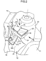
- Fig. 2 is an enlarged view taken in the direction of an arrow 2 in Fig.1;
- Fig.3 is a view showing a state with a relay box removed from Fig. 2;
- Fig. 4 is a view taken in the direction of an arrow 4 in Fig. 2;
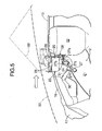
- Fig.5 is a view taken in the direction of an arrow 5 in Fig. 2;
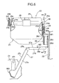
- Fig. 6 is a view taken along a line 6-6 in Fig. 4; and
- Fig. 7 is a sectional view taken along a line 7-7 in Fig.6.
- an engine room in a four-wheel vehicle includes a pair of left and right front side frames 11, 11, a pair of left and right wheel house/damper housings 12, 12 welded to outer side surfaces of the front side frames 11, 11, a pair of left and right wheel house upper members 13, 13 welded to upper surfaces of the wheel house/damper housings 12, 12, a dash board 14 welded between rear ends of the wheel house/damper housings 12, 12, a window shield lower 15 welded to an upper surface of the dash board 14, a pair of left and right front side bulk heads 16, 16 welded to front ends of the wheel house/damper housings 12, 12, a bulk head upper center frame 17 welded between front ends of upper portions of the front side bulk heads 16, 16, and a front lower cross-member 18 welded between front ends of lower portions of the front side bulk heads 16, 16.
- the right wheel house/damper housing 12 is integrally provided with a front wheel house 21 and a rear damper housing 22, and a relay box 23 as a device for the vehicle is supported in a space facing an upper surface of the wheel house 21 and a front surface of the damper housing 22.
- the relay box 23 is of a trapezoidal shape as viewed in a plane and divided into two portions: a main body 24 provided at a lower location and a lid 25 provided at an upper location.
- a bracket 26 for supporting relay box 23 on the front surface of the damper housing 11 is made by pressing a metal plate, and integrally provided with a mounting portion 26a welded at W1 to the front surface of the damper housing 22, a connecting portion 26b extending forwards from a lower edge of the mounting portion 26a, a pair of arm portions 26c, 26c extending forwards from left and right side edges of the mounting portion 26a, and a pair of supporting portions 26d, 26d extending in a lateral direction from the arm portions 26c, 26c.
- Quadrilateral locking bores 26e, 26e are defined in ends of the supporting portions 26d, 26d.
- a deformable member 27 formed into a spread inverted V-shape as viewed from a side is made by pressing a metal plate, and includes a first plate-shaped portion 27a superposed at its rear portion on a lower surface of the connecting portion 26b of the bracket 26 and welded at W2 thereto, and a second plate-shaped portion 27c which is integrally connected to a tip end of the first plate section 27a through a bent portion 27b and extends forwards and downwards and is welded at its front end at W3 to the upper surface of the wheel house 21.
- Reinforcing flanges 27d, 27d and 27e, 27e are integrally formed at opposite side edges of the first and second plate-shaped portions 27a and 27c.
- the relay box 23 includes a rib 24a at an upper edge of the main body 24, which opens upwards, and a groove 25a in a lower end of the lid 25, which opens downwards.
- the body 24 and the lid 25 are integrally connected to each other by five clips 28 with the rib 24a fitted in the groove 25a.
- the five clips 28 are of the same structure.
- a locking claw 24c is provided at an upper end of a plate-shaped portion 24b having a high rigidity and extending upwards from a side of the main body 24, while a locking bore 25c is provided in an upper end of a plate-shaped portion 25b having a low rigidity and extending upwards from a side of the lid 25.
- the plate-shaped portion 25b of the lid 25 pushed by the locking claw 24c of the main body 24 is flexed inwards, whereby the locking claw 24c of the main body 24 is engaged into the locking bore 25c in the lid 25.
- the plate-shaped portion 25b of the lid 25 may be flexed inwards, thereby permitting the locking claw 24c to be disengaged from the locking bore 25c, and in that state, the lid 25 may be withdrawn upwards.
- Each of two clips 29 for releasably supporting the relay box 23 on the supporting portions 26d, 26d of the bracket 26 is of such a structure that a plate 24e supported at its lower portion and flexible at its upper portion is disposed within a guide portion 24d projectingly provided on a side of the main body 24 of the relay box 23 to extend up and down, and a locking claw 24f is provided on an outer side surface of the plate 24e. Therefore, when each of the supporting portion 26d of the bracket 26 is inserted into the guide portion 24d of the clip 29 from below, the plate 24e is flexed, thereby permitting the locking claw 24f to be engaged into the locking bore 26e and thus, the relay box 23 is supported on the supporting portions 26d, 26d of the bracket 26 (see Figs. 4 and 6). In this state, the bent portion 27b of the deformable member 27 is opposed to the central portion of the lower surface of the main body 24 of the relay box 23 (see Fig.6).
- a wire harness 30 leading to the relay body 23 once extends downwards to describe a loop of 360°, and is then fixed by locking a locking claw 31a integral with a ring 31 fitted around an outer periphery of the wire harness 30 to a mounting portion 27f extending from the second plate-shaped portion 27c of the deformable member 27.
- members such as the bulk head upper center frame 17, the front lower cross-member 18, the front side bulk heads 16, 16, the front side frames 11, 11, the wheel house/damper housing 12, 12 and the wheel house upper members 13, 13 are smashed rearwards by the action of a shock from front.
- the right wheel house/damper housing 12 because the rigidity of the damper housing 22 positioned at a rear location is relatively high and the rigidity of the wheel house 21 positioned at a fore location is relatively low, the wheel house 21 is moved rearwards toward the damper housing 22.
- the deformable member 27 is bent at the central bent portion 27b to become deformed into an inverted V-shape as shown by a dashed line in Fig.
- the relay box 23 With the central portion of the lower surface of the main body 24 pushed up by the bent portion 27b is moved upwards.
- the locking claws 24f, 24f of the two clips 29 provided on the main body 24 of the relay box 23 are forcibly disengaged from the locking bores 26e, 26e provided in the supporting portion 26d, 26d of the bracket 26 and thus, the relay box 23 is separated upwards from the bracket 26.
- a bonnet hood 33 covering the engine room is bent upwards at a portion corresponding to above the relay box 23, whereby a space for removal of the relay box 23 is ensured in the bent location, because a stiffener for reinforcing a rear surface of the bonnet hood 33 is disposed at a predetermined location and in a predetermined shape.
- the relay box 23 existing in front of the damper housing 22 of the relatively high rigidity at the rear portion of the wheel house/damper housing 12 can be moved upwards and moreover, the relay box 23 disengaged from the bracket 26 can be moved freely rearwards along the upper surface of the damper housing and hence, a sufficient crush stroke can be ensured in the engine room to absorb a shock due to the collision.
- the upward movement of the relay box 23 cannot be hindered by the wire harness 30, because the wire harness 30 leading to the relay box 23 is disposed with a looseness.
- the relay box 23 Upon the collision of the vehicle, the relay box 23 is retracted upwards, whereby it is difficult for the relay box to be damaged, and it is possible to inhibit, to the minimum, the breakage of a wire and/or the short-circuit from occurring within the relay box 23 to influence another electric equipment.
- the deformable member 27 has been mounted to the wheel house/damper housing 12 in the embodiment, but may be mounted to any other member.
- the relay box 23 has been illustrated as a device for the vehicle in the embodiment, but the present invention is applicable to any device for a vehicle other than the relay box 23.
- the bracket 26 and the clips 29 have been illustrated as a mounting portion of the plug-in structure in the embodiment, but according to the present invention, any mounting portions of a plug-in structure other than them may be employed.
- the present invention is applicable to a structure within a trunk room.
- the hood is a trunk hood rather than the bonnet good 33.
- the structure of mounting of the device for the vehicle according to the present invention can be suitably utilized when the device such as the relay box is mounted in the engine room in the four-wheel vehicle.
Landscapes
- Engineering & Computer Science (AREA)
- Mechanical Engineering (AREA)
- Body Structure For Vehicles (AREA)
Abstract
Description
Claims (6)
- A structure mounting a device for a vehicle, in which the device (23) for the vehicle is mounted to a vehicle body (12) through a mounting portion (26, 29),
wherein a deformable member (27) deformable into a predetermined shape by a load upon collision of the vehicle is mounted to the vehicle body (12), so that the device (23) for the vehicle is pushed and moved in a predetermined direction by the deformation of the deformable member (27), and the device (23) for the vehicle is mounted to the vehicle body (12) through the mounting portion (26, 29), so that the mounting portions (26, 29) is disengaged by the movement of the device (23) in the predetermined direction upon collision of the vehicle, whereby the device (23) is separated from the vehicle body (12),
characterised in that the mounting portion has a plug-in structure and in that the structure mounting a device includes a hood (33) which is bent upwards at a predetermined location by the load upon collision of the vehicle, so that the device (23) for the vehicle is moved toward a space defmed by the bending of said hood (33). - A structure mounting a device for a vehicle according to claim 1, wherein the mounting portion (26, 29) is of a structure in which the coupling of respective parts thereof is released when the amount of deformable member (27) deformed reaches a predetermined value or more.
- A structure mounting a device for a vehicle according to claim 1 or 2, wherein the deformable member (27) is a plate-shaped member having a bent portion (27b), said bent portion (27b) being deformed by a load upon the collision of the vehicle.
- A structure mounting a device for a vehicle according to claim 3, wherein at least a portion of the deformable member (27) is fixed to a damper housing (22).
- A structure mounting a device for a vehicle according to claim 4, wherein the deformable member (27) comprises a first plate-shaped portion (27a) extending forwards from a front surface of the damper housing (22), and a second plate-shaped portion (27c) extending obliquely rearwards from an upper surface of a wheel house (21), said first and second plate-shaped portions (27b and 27c) being integrally coupled to each other at the bent portion (27b), and said bent portion (27b) is located on a lower surface of the device (23) for the vehicle.
- A structure mounting a device for a vehicle according to any one of claims 1 to 5, wherein the device (23) for the vehicle is an electric equipment, and a wire harness (30) leading to said electric equipment is supported loosely on the vehicle body (12).
Applications Claiming Priority (3)
| Application Number | Priority Date | Filing Date | Title |
|---|---|---|---|
| JP2001178218A JP3923280B2 (en) | 2001-06-13 | 2001-06-13 | Mounting structure for vehicle equipment |
| JP2001178218 | 2001-06-13 | ||
| EP02712397A EP1403144B1 (en) | 2001-06-13 | 2002-02-15 | Attaching structure for devices for vehicles |
Related Parent Applications (2)
| Application Number | Title | Priority Date | Filing Date |
|---|---|---|---|
| EP02712397.5 Division | 2002-02-15 | ||
| EP02712397A Division EP1403144B1 (en) | 2001-06-13 | 2002-02-15 | Attaching structure for devices for vehicles |
Publications (2)
| Publication Number | Publication Date |
|---|---|
| EP1547872A1 true EP1547872A1 (en) | 2005-06-29 |
| EP1547872B1 EP1547872B1 (en) | 2006-10-04 |
Family
ID=19018953
Family Applications (2)
| Application Number | Title | Priority Date | Filing Date |
|---|---|---|---|
| EP02712397A Expired - Lifetime EP1403144B1 (en) | 2001-06-13 | 2002-02-15 | Attaching structure for devices for vehicles |
| EP05006935A Expired - Lifetime EP1547872B1 (en) | 2001-06-13 | 2002-02-15 | Structure of mounting of device for vehicle |
Family Applications Before (1)
| Application Number | Title | Priority Date | Filing Date |
|---|---|---|---|
| EP02712397A Expired - Lifetime EP1403144B1 (en) | 2001-06-13 | 2002-02-15 | Attaching structure for devices for vehicles |
Country Status (6)
| Country | Link |
|---|---|
| EP (2) | EP1403144B1 (en) |
| JP (1) | JP3923280B2 (en) |
| CN (1) | CN1273331C (en) |
| DE (2) | DE60207078T2 (en) |
| MY (1) | MY131413A (en) |
| WO (1) | WO2003002379A1 (en) |
Cited By (2)
| Publication number | Priority date | Publication date | Assignee | Title |
|---|---|---|---|---|
| WO2007019923A1 (en) * | 2005-08-16 | 2007-02-22 | Daimlerchrysler Ag | Motor vehicle with remote auxiliary starting point |
| WO2012104721A1 (en) * | 2011-02-03 | 2012-08-09 | Toyota Jidosha Kabushiki Kaisha | Vehicle equipment mounting structure |
Families Citing this family (17)
| Publication number | Priority date | Publication date | Assignee | Title |
|---|---|---|---|---|
| KR101028209B1 (en) * | 2004-12-23 | 2011-04-11 | 현대자동차주식회사 | Mounting structure of electronics box |
| JP4331152B2 (en) | 2005-09-20 | 2009-09-16 | 本田技研工業株式会社 | Object detection device mounting structure |
| DE102008014829B4 (en) | 2008-03-18 | 2023-06-15 | Dr. Ing. H.C. F. Porsche Aktiengesellschaft | Protective housing for a galvanic cell in a motor vehicle |
| FR2938483B1 (en) * | 2008-11-14 | 2011-10-21 | Peugeot Citroen Automobiles Sa | DEVICE FOR MOVING A RIGID ELEMENT, AND VEHICLE EQUIPPED WITH SUCH A DEVICE |
| JP2011178182A (en) | 2010-02-26 | 2011-09-15 | Suzuki Motor Corp | Fuel filter mounting structure of vehicle |
| CN103547470B (en) * | 2011-05-20 | 2016-05-25 | 丰田自动车株式会社 | Vehicle equipment loading structure |
| JP5983361B2 (en) * | 2012-11-28 | 2016-08-31 | スズキ株式会社 | Vehicle harness connector protection structure |
| JP6235355B2 (en) * | 2014-01-27 | 2017-11-22 | 株式会社Subaru | Radar mounting structure |
| FR3024859B1 (en) * | 2014-08-14 | 2016-07-29 | Renault Sa | ARRANGEMENT FOR A MOTOR VEHICLE WITH AN ELECTRONIC HOUSING SUPPORT ARRANGED IN FRONT OF A FRONT WHEEL PASSAGE ELEMENT |
| DE102014222441A1 (en) * | 2014-11-04 | 2016-05-04 | Bayerische Motoren Werke Aktiengesellschaft | Motor vehicle and method for producing a motor vehicle |
| JP6090297B2 (en) * | 2014-12-12 | 2017-03-08 | マツダ株式会社 | Installation structure of in-vehicle equipment |
| JP6485223B2 (en) * | 2015-05-28 | 2019-03-20 | スズキ株式会社 | Controller mounting structure |
| DE102015011824A1 (en) * | 2015-09-09 | 2017-03-09 | GM Global Technology Operations LLC (n. d. Gesetzen des Staates Delaware) | A protective cover for an electronic device in a vehicle, boot assembly for a vehicle and vehicle with the boot assembly |
| FR3040940B1 (en) * | 2015-09-10 | 2017-09-01 | Renault Sas | ELECTRIC DEVICE INCLINED ABOVE A VEHICLE WHEEL PASSAGE |
| KR102045405B1 (en) * | 2019-04-26 | 2019-11-15 | 한국단자공업 주식회사 | Block for vehicle |
| JP7322546B2 (en) | 2019-06-25 | 2023-08-08 | スズキ株式会社 | Protective structures for vehicle electrical equipment |
| FR3111309B1 (en) * | 2020-06-16 | 2022-09-09 | Psa Automobiles Sa | VEHICLE WITH SUPPORT PIECE PROTECTING LIQUID RUNS AN ELECTRONIC BOX |
Citations (3)
| Publication number | Priority date | Publication date | Assignee | Title |
|---|---|---|---|---|
| DE4331900A1 (en) * | 1992-09-30 | 1994-03-31 | Volkswagen Ag | Road vehicle front section - contains operating devices and accommodation for battery inclined at specific angle |
| US5542491A (en) * | 1994-01-05 | 1996-08-06 | Mercedes Benz-Ag | Scuttle structure for a motor vehicle having a drive unit arranged at the front |
| DE19651495C1 (en) * | 1996-12-11 | 1998-03-05 | Daimler Benz Ag | Car body |
Family Cites Families (3)
| Publication number | Priority date | Publication date | Assignee | Title |
|---|---|---|---|---|
| JPS5316567B2 (en) * | 1973-01-09 | 1978-06-02 | ||
| JP3551519B2 (en) * | 1995-01-19 | 2004-08-11 | トヨタ自動車株式会社 | Fuel cell system vehicle mounting structure and fuel cell storage case |
| FR2813253B1 (en) * | 2000-08-25 | 2002-11-01 | Renault | SAFETY ARRANGEMENT FOR MOUNTING A BATTERY |
-
2001
- 2001-06-13 JP JP2001178218A patent/JP3923280B2/en not_active Expired - Fee Related
-
2002
- 2002-02-15 DE DE60207078T patent/DE60207078T2/en not_active Expired - Lifetime
- 2002-02-15 CN CN 02811825 patent/CN1273331C/en not_active Expired - Fee Related
- 2002-02-15 EP EP02712397A patent/EP1403144B1/en not_active Expired - Lifetime
- 2002-02-15 DE DE2002615229 patent/DE60215229T2/en not_active Expired - Lifetime
- 2002-02-15 WO PCT/JP2002/001318 patent/WO2003002379A1/en not_active Ceased
- 2002-02-15 EP EP05006935A patent/EP1547872B1/en not_active Expired - Lifetime
- 2002-06-12 MY MYPI20022189 patent/MY131413A/en unknown
Patent Citations (3)
| Publication number | Priority date | Publication date | Assignee | Title |
|---|---|---|---|---|
| DE4331900A1 (en) * | 1992-09-30 | 1994-03-31 | Volkswagen Ag | Road vehicle front section - contains operating devices and accommodation for battery inclined at specific angle |
| US5542491A (en) * | 1994-01-05 | 1996-08-06 | Mercedes Benz-Ag | Scuttle structure for a motor vehicle having a drive unit arranged at the front |
| DE19651495C1 (en) * | 1996-12-11 | 1998-03-05 | Daimler Benz Ag | Car body |
Cited By (2)
| Publication number | Priority date | Publication date | Assignee | Title |
|---|---|---|---|---|
| WO2007019923A1 (en) * | 2005-08-16 | 2007-02-22 | Daimlerchrysler Ag | Motor vehicle with remote auxiliary starting point |
| WO2012104721A1 (en) * | 2011-02-03 | 2012-08-09 | Toyota Jidosha Kabushiki Kaisha | Vehicle equipment mounting structure |
Also Published As
| Publication number | Publication date |
|---|---|
| WO2003002379A1 (en) | 2003-01-09 |
| WO2003002379B1 (en) | 2003-03-27 |
| MY131413A (en) | 2007-08-30 |
| DE60215229D1 (en) | 2006-11-16 |
| CN1531490A (en) | 2004-09-22 |
| JP2003034198A (en) | 2003-02-04 |
| EP1403144A1 (en) | 2004-03-31 |
| EP1403144A4 (en) | 2004-08-11 |
| CN1273331C (en) | 2006-09-06 |
| DE60215229T2 (en) | 2007-02-01 |
| EP1403144B1 (en) | 2005-11-02 |
| EP1547872B1 (en) | 2006-10-04 |
| DE60207078T2 (en) | 2006-04-20 |
| DE60207078D1 (en) | 2005-12-08 |
| JP3923280B2 (en) | 2007-05-30 |
Similar Documents
| Publication | Publication Date | Title |
|---|---|---|
| EP1547872B1 (en) | Structure of mounting of device for vehicle | |
| JP3923281B2 (en) | Mounting structure for vehicle equipment | |
| CN100398381C (en) | Vehicle front body structure | |
| JP3979016B2 (en) | Auto body front structure | |
| CN110893761B (en) | Vehicle underfloor structure | |
| JP5609972B2 (en) | Automotive dash panel structure | |
| JP2020044992A (en) | vehicle | |
| JP2020050122A (en) | Vehicle body front structure | |
| JP6299830B1 (en) | Front vehicle structure | |
| JP7122289B2 (en) | vehicle | |
| JP2020011608A (en) | Power supply fixing structure for vehicles | |
| CN110893760B (en) | Vehicle underfloor structure | |
| JP7432136B2 (en) | Electric vehicle power unit mounting structure | |
| JP7354734B2 (en) | bracket | |
| CN214295545U (en) | Protective casing for vehicle | |
| JPH0299440A (en) | Mounting construction for automotive electric equipment | |
| JP7268607B2 (en) | vehicle front structure | |
| EP1666310A1 (en) | Wire harness installation structure | |
| CN113540675B (en) | Automobile battery limiting block, automobile battery protection device and automobile | |
| JP7639047B2 (en) | Wire protection structure | |
| JP7639048B2 (en) | Wire protection structure | |
| CN214356285U (en) | Vehicle front structure | |
| JP6413453B2 (en) | Cable routing structure for vehicles | |
| JP7456302B2 (en) | Vehicle battery protection structure | |
| JP4225148B2 (en) | Electrical junction box |
Legal Events
| Date | Code | Title | Description |
|---|---|---|---|
| PUAI | Public reference made under article 153(3) epc to a published international application that has entered the european phase |
Free format text: ORIGINAL CODE: 0009012 |
|
| AC | Divisional application: reference to earlier application |
Ref document number: 1403144 Country of ref document: EP Kind code of ref document: P |
|
| AK | Designated contracting states |
Kind code of ref document: A1 Designated state(s): DE GB |
|
| 17P | Request for examination filed |
Effective date: 20051124 |
|
| AKX | Designation fees paid |
Designated state(s): DE GB |
|
| GRAP | Despatch of communication of intention to grant a patent |
Free format text: ORIGINAL CODE: EPIDOSNIGR1 |
|
| GRAS | Grant fee paid |
Free format text: ORIGINAL CODE: EPIDOSNIGR3 |
|
| GRAA | (expected) grant |
Free format text: ORIGINAL CODE: 0009210 |
|
| AC | Divisional application: reference to earlier application |
Ref document number: 1403144 Country of ref document: EP Kind code of ref document: P |
|
| AK | Designated contracting states |
Kind code of ref document: B1 Designated state(s): DE GB |
|
| REG | Reference to a national code |
Ref country code: GB Ref legal event code: FG4D |
|
| REF | Corresponds to: |
Ref document number: 60215229 Country of ref document: DE Date of ref document: 20061116 Kind code of ref document: P |
|
| PLBE | No opposition filed within time limit |
Free format text: ORIGINAL CODE: 0009261 |
|
| STAA | Information on the status of an ep patent application or granted ep patent |
Free format text: STATUS: NO OPPOSITION FILED WITHIN TIME LIMIT |
|
| 26N | No opposition filed |
Effective date: 20070705 |
|
| PGFP | Annual fee paid to national office [announced via postgrant information from national office to epo] |
Ref country code: GB Payment date: 20140212 Year of fee payment: 13 |
|
| PGFP | Annual fee paid to national office [announced via postgrant information from national office to epo] |
Ref country code: DE Payment date: 20140417 Year of fee payment: 13 |
|
| REG | Reference to a national code |
Ref country code: DE Ref legal event code: R119 Ref document number: 60215229 Country of ref document: DE |
|
| GBPC | Gb: european patent ceased through non-payment of renewal fee |
Effective date: 20150215 |
|
| PG25 | Lapsed in a contracting state [announced via postgrant information from national office to epo] |
Ref country code: DE Free format text: LAPSE BECAUSE OF NON-PAYMENT OF DUE FEES Effective date: 20150901 Ref country code: GB Free format text: LAPSE BECAUSE OF NON-PAYMENT OF DUE FEES Effective date: 20150215 |