EP1547865A1 - Signalling or lighting device, in particular for motor vehicle - Google Patents
Signalling or lighting device, in particular for motor vehicle Download PDFInfo
- Publication number
- EP1547865A1 EP1547865A1 EP04292894A EP04292894A EP1547865A1 EP 1547865 A1 EP1547865 A1 EP 1547865A1 EP 04292894 A EP04292894 A EP 04292894A EP 04292894 A EP04292894 A EP 04292894A EP 1547865 A1 EP1547865 A1 EP 1547865A1
- Authority
- EP
- European Patent Office
- Prior art keywords
- light
- source
- guide
- guides
- signaling
- Prior art date
- Legal status (The legal status is an assumption and is not a legal conclusion. Google has not performed a legal analysis and makes no representation as to the accuracy of the status listed.)
- Granted
Links
- 230000011664 signaling Effects 0.000 title claims abstract description 29
- 230000006870 function Effects 0.000 claims abstract description 28
- 230000003287 optical effect Effects 0.000 claims abstract description 25
- 230000009131 signaling function Effects 0.000 claims abstract description 8
- 238000009792 diffusion process Methods 0.000 claims description 5
- 230000007935 neutral effect Effects 0.000 claims description 4
- 230000004907 flux Effects 0.000 claims description 3
- 239000012780 transparent material Substances 0.000 claims description 3
- 230000005540 biological transmission Effects 0.000 claims 1
- 238000002347 injection Methods 0.000 description 4
- 239000007924 injection Substances 0.000 description 4
- 239000000463 material Substances 0.000 description 3
- 229920003023 plastic Polymers 0.000 description 3
- 230000006978 adaptation Effects 0.000 description 2
- 230000000295 complement effect Effects 0.000 description 2
- 230000000694 effects Effects 0.000 description 2
- 238000004519 manufacturing process Methods 0.000 description 2
- 239000004033 plastic Substances 0.000 description 2
- 229920000297 Rayon Polymers 0.000 description 1
- 238000000149 argon plasma sintering Methods 0.000 description 1
- 238000000151 deposition Methods 0.000 description 1
- 238000010586 diagram Methods 0.000 description 1
- 239000000835 fiber Substances 0.000 description 1
- 239000012530 fluid Substances 0.000 description 1
- 239000011521 glass Substances 0.000 description 1
- 238000005286 illumination Methods 0.000 description 1
- 238000012886 linear function Methods 0.000 description 1
- 239000011104 metalized film Substances 0.000 description 1
- 229910052754 neon Inorganic materials 0.000 description 1
- GKAOGPIIYCISHV-UHFFFAOYSA-N neon atom Chemical compound [Ne] GKAOGPIIYCISHV-UHFFFAOYSA-N 0.000 description 1
- 239000002964 rayon Substances 0.000 description 1
- 238000004381 surface treatment Methods 0.000 description 1
- 238000004804 winding Methods 0.000 description 1
Images


Classifications
-
- G—PHYSICS
- G02—OPTICS
- G02B—OPTICAL ELEMENTS, SYSTEMS OR APPARATUS
- G02B6/00—Light guides; Structural details of arrangements comprising light guides and other optical elements, e.g. couplings
- G02B6/0001—Light guides; Structural details of arrangements comprising light guides and other optical elements, e.g. couplings specially adapted for lighting devices or systems
- G02B6/0005—Light guides; Structural details of arrangements comprising light guides and other optical elements, e.g. couplings specially adapted for lighting devices or systems the light guides being of the fibre type
- G02B6/0006—Coupling light into the fibre
-
- B—PERFORMING OPERATIONS; TRANSPORTING
- B60—VEHICLES IN GENERAL
- B60Q—ARRANGEMENT OF SIGNALLING OR LIGHTING DEVICES, THE MOUNTING OR SUPPORTING THEREOF OR CIRCUITS THEREFOR, FOR VEHICLES IN GENERAL
- B60Q1/00—Arrangement of optical signalling or lighting devices, the mounting or supporting thereof or circuits therefor
- B60Q1/26—Arrangement of optical signalling or lighting devices, the mounting or supporting thereof or circuits therefor the devices being primarily intended to indicate the vehicle, or parts thereof, or to give signals, to other traffic
- B60Q1/2696—Mounting of devices using LEDs
-
- B—PERFORMING OPERATIONS; TRANSPORTING
- B60—VEHICLES IN GENERAL
- B60Q—ARRANGEMENT OF SIGNALLING OR LIGHTING DEVICES, THE MOUNTING OR SUPPORTING THEREOF OR CIRCUITS THEREFOR, FOR VEHICLES IN GENERAL
- B60Q1/00—Arrangement of optical signalling or lighting devices, the mounting or supporting thereof or circuits therefor
- B60Q1/26—Arrangement of optical signalling or lighting devices, the mounting or supporting thereof or circuits therefor the devices being primarily intended to indicate the vehicle, or parts thereof, or to give signals, to other traffic
- B60Q1/30—Arrangement of optical signalling or lighting devices, the mounting or supporting thereof or circuits therefor the devices being primarily intended to indicate the vehicle, or parts thereof, or to give signals, to other traffic for indicating rear of vehicle, e.g. by means of reflecting surfaces
- B60Q1/302—Arrangement of optical signalling or lighting devices, the mounting or supporting thereof or circuits therefor the devices being primarily intended to indicate the vehicle, or parts thereof, or to give signals, to other traffic for indicating rear of vehicle, e.g. by means of reflecting surfaces mounted in the vicinity, e.g. in the middle, of a rear window
-
- B—PERFORMING OPERATIONS; TRANSPORTING
- B60—VEHICLES IN GENERAL
- B60Q—ARRANGEMENT OF SIGNALLING OR LIGHTING DEVICES, THE MOUNTING OR SUPPORTING THEREOF OR CIRCUITS THEREFOR, FOR VEHICLES IN GENERAL
- B60Q3/00—Arrangement of lighting devices for vehicle interiors; Lighting devices specially adapted for vehicle interiors
- B60Q3/60—Arrangement of lighting devices for vehicle interiors; Lighting devices specially adapted for vehicle interiors characterised by optical aspects
- B60Q3/62—Arrangement of lighting devices for vehicle interiors; Lighting devices specially adapted for vehicle interiors characterised by optical aspects using light guides
- B60Q3/64—Arrangement of lighting devices for vehicle interiors; Lighting devices specially adapted for vehicle interiors characterised by optical aspects using light guides for a single lighting device
-
- F—MECHANICAL ENGINEERING; LIGHTING; HEATING; WEAPONS; BLASTING
- F21—LIGHTING
- F21S—NON-PORTABLE LIGHTING DEVICES; SYSTEMS THEREOF; VEHICLE LIGHTING DEVICES SPECIALLY ADAPTED FOR VEHICLE EXTERIORS
- F21S41/00—Illuminating devices specially adapted for vehicle exteriors, e.g. headlamps
-
- F—MECHANICAL ENGINEERING; LIGHTING; HEATING; WEAPONS; BLASTING
- F21—LIGHTING
- F21S—NON-PORTABLE LIGHTING DEVICES; SYSTEMS THEREOF; VEHICLE LIGHTING DEVICES SPECIALLY ADAPTED FOR VEHICLE EXTERIORS
- F21S41/00—Illuminating devices specially adapted for vehicle exteriors, e.g. headlamps
- F21S41/10—Illuminating devices specially adapted for vehicle exteriors, e.g. headlamps characterised by the light source
- F21S41/14—Illuminating devices specially adapted for vehicle exteriors, e.g. headlamps characterised by the light source characterised by the type of light source
- F21S41/141—Light emitting diodes [LED]
- F21S41/143—Light emitting diodes [LED] the main emission direction of the LED being parallel to the optical axis of the illuminating device
-
- F—MECHANICAL ENGINEERING; LIGHTING; HEATING; WEAPONS; BLASTING
- F21—LIGHTING
- F21S—NON-PORTABLE LIGHTING DEVICES; SYSTEMS THEREOF; VEHICLE LIGHTING DEVICES SPECIALLY ADAPTED FOR VEHICLE EXTERIORS
- F21S41/00—Illuminating devices specially adapted for vehicle exteriors, e.g. headlamps
- F21S41/20—Illuminating devices specially adapted for vehicle exteriors, e.g. headlamps characterised by refractors, transparent cover plates, light guides or filters
- F21S41/24—Light guides
-
- F—MECHANICAL ENGINEERING; LIGHTING; HEATING; WEAPONS; BLASTING
- F21—LIGHTING
- F21S—NON-PORTABLE LIGHTING DEVICES; SYSTEMS THEREOF; VEHICLE LIGHTING DEVICES SPECIALLY ADAPTED FOR VEHICLE EXTERIORS
- F21S41/00—Illuminating devices specially adapted for vehicle exteriors, e.g. headlamps
- F21S41/20—Illuminating devices specially adapted for vehicle exteriors, e.g. headlamps characterised by refractors, transparent cover plates, light guides or filters
- F21S41/285—Refractors, transparent cover plates, light guides or filters not provided in groups F21S41/24 - F21S41/2805
-
- F—MECHANICAL ENGINEERING; LIGHTING; HEATING; WEAPONS; BLASTING
- F21—LIGHTING
- F21S—NON-PORTABLE LIGHTING DEVICES; SYSTEMS THEREOF; VEHICLE LIGHTING DEVICES SPECIALLY ADAPTED FOR VEHICLE EXTERIORS
- F21S41/00—Illuminating devices specially adapted for vehicle exteriors, e.g. headlamps
- F21S41/30—Illuminating devices specially adapted for vehicle exteriors, e.g. headlamps characterised by reflectors
- F21S41/32—Optical layout thereof
- F21S41/322—Optical layout thereof the reflector using total internal reflection
-
- F—MECHANICAL ENGINEERING; LIGHTING; HEATING; WEAPONS; BLASTING
- F21—LIGHTING
- F21S—NON-PORTABLE LIGHTING DEVICES; SYSTEMS THEREOF; VEHICLE LIGHTING DEVICES SPECIALLY ADAPTED FOR VEHICLE EXTERIORS
- F21S43/00—Signalling devices specially adapted for vehicle exteriors, e.g. brake lamps, direction indicator lights or reversing lights
- F21S43/10—Signalling devices specially adapted for vehicle exteriors, e.g. brake lamps, direction indicator lights or reversing lights characterised by the light source
- F21S43/13—Signalling devices specially adapted for vehicle exteriors, e.g. brake lamps, direction indicator lights or reversing lights characterised by the light source characterised by the type of light source
- F21S43/14—Light emitting diodes [LED]
-
- F—MECHANICAL ENGINEERING; LIGHTING; HEATING; WEAPONS; BLASTING
- F21—LIGHTING
- F21S—NON-PORTABLE LIGHTING DEVICES; SYSTEMS THEREOF; VEHICLE LIGHTING DEVICES SPECIALLY ADAPTED FOR VEHICLE EXTERIORS
- F21S43/00—Signalling devices specially adapted for vehicle exteriors, e.g. brake lamps, direction indicator lights or reversing lights
- F21S43/10—Signalling devices specially adapted for vehicle exteriors, e.g. brake lamps, direction indicator lights or reversing lights characterised by the light source
- F21S43/13—Signalling devices specially adapted for vehicle exteriors, e.g. brake lamps, direction indicator lights or reversing lights characterised by the light source characterised by the type of light source
- F21S43/15—Strips of light sources
-
- F—MECHANICAL ENGINEERING; LIGHTING; HEATING; WEAPONS; BLASTING
- F21—LIGHTING
- F21S—NON-PORTABLE LIGHTING DEVICES; SYSTEMS THEREOF; VEHICLE LIGHTING DEVICES SPECIALLY ADAPTED FOR VEHICLE EXTERIORS
- F21S43/00—Signalling devices specially adapted for vehicle exteriors, e.g. brake lamps, direction indicator lights or reversing lights
- F21S43/20—Signalling devices specially adapted for vehicle exteriors, e.g. brake lamps, direction indicator lights or reversing lights characterised by refractors, transparent cover plates, light guides or filters
- F21S43/235—Light guides
- F21S43/236—Light guides characterised by the shape of the light guide
- F21S43/237—Light guides characterised by the shape of the light guide rod-shaped
-
- F—MECHANICAL ENGINEERING; LIGHTING; HEATING; WEAPONS; BLASTING
- F21—LIGHTING
- F21S—NON-PORTABLE LIGHTING DEVICES; SYSTEMS THEREOF; VEHICLE LIGHTING DEVICES SPECIALLY ADAPTED FOR VEHICLE EXTERIORS
- F21S43/00—Signalling devices specially adapted for vehicle exteriors, e.g. brake lamps, direction indicator lights or reversing lights
- F21S43/20—Signalling devices specially adapted for vehicle exteriors, e.g. brake lamps, direction indicator lights or reversing lights characterised by refractors, transparent cover plates, light guides or filters
- F21S43/235—Light guides
- F21S43/242—Light guides characterised by the emission area
- F21S43/245—Light guides characterised by the emission area emitting light from one or more of its major surfaces
-
- F—MECHANICAL ENGINEERING; LIGHTING; HEATING; WEAPONS; BLASTING
- F21—LIGHTING
- F21S—NON-PORTABLE LIGHTING DEVICES; SYSTEMS THEREOF; VEHICLE LIGHTING DEVICES SPECIALLY ADAPTED FOR VEHICLE EXTERIORS
- F21S43/00—Signalling devices specially adapted for vehicle exteriors, e.g. brake lamps, direction indicator lights or reversing lights
- F21S43/20—Signalling devices specially adapted for vehicle exteriors, e.g. brake lamps, direction indicator lights or reversing lights characterised by refractors, transparent cover plates, light guides or filters
- F21S43/235—Light guides
- F21S43/249—Light guides with two or more light sources being coupled into the light guide
-
- F—MECHANICAL ENGINEERING; LIGHTING; HEATING; WEAPONS; BLASTING
- F21—LIGHTING
- F21S—NON-PORTABLE LIGHTING DEVICES; SYSTEMS THEREOF; VEHICLE LIGHTING DEVICES SPECIALLY ADAPTED FOR VEHICLE EXTERIORS
- F21S43/00—Signalling devices specially adapted for vehicle exteriors, e.g. brake lamps, direction indicator lights or reversing lights
- F21S43/20—Signalling devices specially adapted for vehicle exteriors, e.g. brake lamps, direction indicator lights or reversing lights characterised by refractors, transparent cover plates, light guides or filters
- F21S43/26—Refractors, transparent cover plates, light guides or filters not provided in groups F21S43/235 - F21S43/255
-
- F—MECHANICAL ENGINEERING; LIGHTING; HEATING; WEAPONS; BLASTING
- F21—LIGHTING
- F21S—NON-PORTABLE LIGHTING DEVICES; SYSTEMS THEREOF; VEHICLE LIGHTING DEVICES SPECIALLY ADAPTED FOR VEHICLE EXTERIORS
- F21S43/00—Signalling devices specially adapted for vehicle exteriors, e.g. brake lamps, direction indicator lights or reversing lights
- F21S43/30—Signalling devices specially adapted for vehicle exteriors, e.g. brake lamps, direction indicator lights or reversing lights characterised by reflectors
- F21S43/31—Optical layout thereof
- F21S43/315—Optical layout thereof using total internal reflection
-
- F—MECHANICAL ENGINEERING; LIGHTING; HEATING; WEAPONS; BLASTING
- F21—LIGHTING
- F21S—NON-PORTABLE LIGHTING DEVICES; SYSTEMS THEREOF; VEHICLE LIGHTING DEVICES SPECIALLY ADAPTED FOR VEHICLE EXTERIORS
- F21S43/00—Signalling devices specially adapted for vehicle exteriors, e.g. brake lamps, direction indicator lights or reversing lights
- F21S43/40—Signalling devices specially adapted for vehicle exteriors, e.g. brake lamps, direction indicator lights or reversing lights characterised by the combination of reflectors and refractors
-
- F—MECHANICAL ENGINEERING; LIGHTING; HEATING; WEAPONS; BLASTING
- F21—LIGHTING
- F21W—INDEXING SCHEME ASSOCIATED WITH SUBCLASSES F21K, F21L, F21S and F21V, RELATING TO USES OR APPLICATIONS OF LIGHTING DEVICES OR SYSTEMS
- F21W2103/00—Exterior vehicle lighting devices for signalling purposes
- F21W2103/20—Direction indicator lights
-
- F—MECHANICAL ENGINEERING; LIGHTING; HEATING; WEAPONS; BLASTING
- F21—LIGHTING
- F21W—INDEXING SCHEME ASSOCIATED WITH SUBCLASSES F21K, F21L, F21S and F21V, RELATING TO USES OR APPLICATIONS OF LIGHTING DEVICES OR SYSTEMS
- F21W2103/00—Exterior vehicle lighting devices for signalling purposes
- F21W2103/35—Brake lights
-
- F—MECHANICAL ENGINEERING; LIGHTING; HEATING; WEAPONS; BLASTING
- F21—LIGHTING
- F21W—INDEXING SCHEME ASSOCIATED WITH SUBCLASSES F21K, F21L, F21S and F21V, RELATING TO USES OR APPLICATIONS OF LIGHTING DEVICES OR SYSTEMS
- F21W2103/00—Exterior vehicle lighting devices for signalling purposes
- F21W2103/45—Reversing lights
Definitions
- the invention relates to a device for signaling or lighting, in particular for vehicles automobile, of the kind that includes at least one light source admitting a main direction of emission, and at least one elongated light guide one end is lit by the source, this guide being able to diffuse the light transversely to its length.
- EP-A-0 515 921 shows a device of this type intended to provide illumination inside the vehicle by being incorporated in a door handle.
- intensity luminous in a direction orthogonal to the length of the light guide does not present a privileged area and remains relatively weak.
- a device for signaling or lighting generally oriented towards the outside of a vehicle, makes it possible to attract the attention of other motorists or pedestrians.
- the object of the invention is therefore, above all, to provide a signaling or lighting device of the kind defined previously that allows to better exploit the light issued by the source and to provide at least one area to strong luminous intensity combined with at least one zone of illuminating light guide with less intensity.
- the invention also aims to provide a signaling or lighting device which, while being simple and robust, allows you to clearly mark zones of a vehicle.
- a signaling device or lighting of the kind defined above is characterized in that the light guide, at least in the vicinity of the source, has a longitudinal axis arranged transversely to the main direction of issue of so that a part of the luminous flux of the source ensures, independently of the guide, a first function of signaling or lighting at light intensity relatively high, and that a second function of signaling or linear lighting, intensity less luminous, is ensured according to the length of the guide from light.
- the light source can emit also in oblique directions, and the source provides the first signaling or lighting function following the main direction of issue, while the second signaling or linear lighting function is ensured according to the length of the light guide by emission in oblique directions.
- the device comprises a system optical associated with the light source to focus the emission following the main direction.
- the first one signaling or lighting function, provided directly by the source, is thus reinforced.
- the light source comprises at minus a light-emitting diode that illuminates substantially on a half-sphere, and the light guide, at least in the vicinity of the source, at its longitudinal axis orthogonal to the main direction of emission.
- Light guides can be straight or curvilinear.
- the light source can be placed in a central position between at least two light guides, particularly symmetrical with respect to the source, particular aligned.
- the optical system associated with the light source to focus the show can include a windshield in transparent material with oriented facets following appropriate angles to ensure reflections internal light before it leaves and fill a target function.
- a windshield in transparent material with oriented facets following appropriate angles to ensure reflections internal light before it leaves and fill a target function.
- Such an optical system is also called "Light engine”.
- the device may include several sources of light connected by diffusion light guides cross.
- a light guide may include at least one neutral zone not ensuring cross-scattering of the light.
- the device may include a lens convergent having a convex face applied against the source and oriented to create the main beam.
- a convergent lens can be provided for the end of each guide next to the source for collimate the light rays in the guide.
- Waveguides located on both sides of the source can form a single piece with a housing for the light source, the faces of the housing corresponding to the end of the waveguides being convexes to focus the light rays in the guides.
- the diffusion of light by the guide is ensured by a face located at the rear relative to the emission.
- This face has streaks, or micro-patterns optics, and is preferably metallized for better return the light.
- the width of the diffusing band can be determined to widen the apparent luminance field at an angle of ⁇ 10 ° for example.
- the source comprises several sources elementary elements divided into at least two subassemblies, one of these subsets being associated with an optical system to provide a main signaling function or lighting, another subset cooperating with at least a light guide to ensure a secondary function of great length.
- the invention consists, apart from the provisions outlined above, in a number of other provisions which will be more explicitly discussed below about examples of realization described with reference to the attached drawings, but which are not limiting.
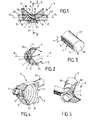
- a signaling device S for vehicle car intended to ensure a function "raised stop” also referred to as CHMLS (Central High Mounted) Lamp Stop).
- CHMLS Central High Mounted Lamp Stop
- the signaling device or lighting system according to the invention is not limited to this type of function.
- the device comprises a light source L constituted by a light-emitting diode 1 suitable for emit, upwards according to Fig.1, in one direction main X-X and following oblique directions B by report to the senior management X-X.
- a light source L constituted by a light-emitting diode 1 suitable for emit, upwards according to Fig.1, in one direction main X-X and following oblique directions B by report to the senior management X-X.
- An elongated G1 light guide is arranged with its longitudinal axis Y1 transversely oriented, at least neighborhood of the diode 1.
- the axis Y1 is orthogonal to the main direction of X-X emission.
- the G1 light guide may consist of a fiber optical, for example cylindrical with straight section circular as illustrated in FIG. 3. The cross section could be different from a circle.
- the face E1 end of the guide G1 neighbor of the source L is orthogonal to the Y1 axis.
- a direction B is considered oblique when tilted with respect to the X-X direction at a sufficient angle to enter the G1 guide by the face E1.
- This angle can be of the order of 30 °.
- the outer surface 1a of the emitting zone of the diode 1 is substantially hemispherical.
- the face E1 is tangent to the surface 1a, parallel to the X-X direction.
- the guide G1 extends on the opposite side to the diode 1 on a relatively large length, especially greater than 500 mm, the diameter of the guide G1 being of the order of 8 mm.
- a second light guide G2 is advantageously provided in the alignment of G1, symmetrically with respect to XX.
- the longitudinal axis Y2 of the guide G2 is in the alignment of Y1.
- An optical system 2 is associated with the source luminous L to focus the emission following the X-X direction.
- the optical system 2 includes a windshield 3 transparent material, for example plastic.
- This windshield 3 forms a cup whose concavity is turned on the opposite side to the diode 1.
- the section cross-section of the concave surface of the windshield formed by steps 3a at right angles provided for ensure a concentration of light rays like illustrated in FIG. 2 to the X-X axis.
- the rear surface 3b the windshield is substantially frustoconical and inclined from an angle favoring internal reflections.
- Layer 3c forming lenses can be provided on the annular zones of tiers 3a located in orthogonal planes to the X-X direction. Pavers 3c to forward convex surface are provided to accentuate the phenomenon of concentration of light rays.
- the part center of the concave area of the windshield forms a semi-convex lens 4 whose convex face is turned to the led 1.
- the windshield 3 comprises two cylindrical housings diametrically opposed 5a, 5b of axis orthogonal to the direction X-X and fit to receive, in an adjusted way, the end of the guides G1, G2.
- the surface F of the guides G1, G2 located opposite the light output in the X-X direction is processed to return the light transversely to the axes Y1, Y2 guides, on the same side as the next main show the X-X direction.
- the treated surface F may comprise streaks or saw teeth 6 forming Fresnel prisms at triangular section of orthogonal edge to the axes Y1, Y2 and to the X-X direction. Prisms thus formed can constitute the rear face of a blade 7 (Fig.3) integrated to tubular guides G1, G2 during manufacture made by injection of transparent plastic material in a mold.
- the face 8 is set in a parallel direction to the Y1, Y2 axis while remaining orthogonal to the direction XX.
- the surface F in particular the oblique faces of sawtooth 6, can be metallized.
- Sawtooth 6 could be replaced by optical micro-patterns (holes of suitable shape in the material) to improve the homogenous appearance of the light.
- These optical micro-motifs are obtained in particular either directly by laser attack of the rear face 8 of the guide G1, G2, or via patterns made in the mold during the injection. In this case the sawtooth 6 and / or the blade 7 would not be used.
- the width h (FIG. 3) of the diffusing band is calculated to widen the field apparent luminance for an observer.
- the angle of the luminance field is +/- 10 ° in relation to the horizontal plane.
- this angle of the field of luminance is chosen more important in order to increase the visibility area in a horizontal plane.
- the cylindrical shape of the G1 guide allows to obtain an enlargement of the diffusing zone by a classic magnifying glass effect.
- the operation of the signaling device is the next.
- LED 1 When LED 1 is on, an emission the main one is in the X-X direction. intensity light is concentrated by lens 4 and by optical device constituted by the windshield 3.
- This signaling function is concentrated with a relatively high light intensity.
- a second signaling function of great length, homogeneous, is obtained on both sides of the windshield 3 according to the length of the guides G1, G2 from oblique rays such as B which undergo reflections internal in the guides to be returned by the surface F forward, that is, on the same side as the broadcast main.
- Fig.6 shows the optical system with both guides G1, G2 of great length extending from other of the windshield 3.
- Light guides allow, for example, to follow the turn of the rear window, or follow a part of the bodywork or the vehicle body.
- two guides diametrically opposed are provided on both sides of the led 1.
- the total length of the light guides can exceed 1300 mm.
- the shape of the guide is adaptable in depending on the style of the vehicle carrier.
- the central piece formed by the windshield 3 can be round or rectangular with a large dimension of the order of 20 to 30mm depending on the needs.
- a convergent lens M on the input face of the light guide in order to collimate, that is, to render essentially parallel, the light beam at inside the guide and thus increase the luminance towards the end N1 (Figs.3 and 6) of the guide remote from the led 1.
- This end N1 (FIG. 3) is advantageously formed by a plane face, orthogonal to the axis longitudinal guide and metallized to return the light inside guide G1 or G2.
- the yield bright system is thus improved.
- Fig.8 shows an asymmetric arrangement with two 3 and two corresponding juxtaposed sources, one only G1 light guide being associated with each windshield.
- the two light guides G1 are parallel, substantially vertical and rectilinear, and arranged on the same side of windscreens 3.
- Fig.9 shows a provision with windshield 3 and light source in the center and a G1a light guide starting from this windshield and winding appreciably following a circular spiral with two towers located in a plan.
- Fig.10 shows a signaling device with center windshield 3 with the source of light.
- Two diametrically opposed light guides G1b, G2b leave this windshield and roll up noticeably on a half-turn in the opposite direction, in the same plane, so that the whole pattern has the shape of an S.
- the curves formed by the guides of light can be left curves, not located in a map.
- Fig.11 shows an alternative embodiment of Fig.8, with the two horizontal parallel G1 guides, and located on the same side.
- Symmetrical versions are obtained by arranging a main source of light in the center of the system, or at each end.
- the asymmetric versions can be isolated, or grouped together in multiple copies (two or more assembled as shown in Fig.8 and 11) to increase performance optics in order to be able to perform the most demanding in luminous flux.
- Versions can be linear (Fig.8 and 11) or circular (Fig.9) or more or less curves (Fig.10), which allows an adaptation to the constraints required by style or form.
- Fig.12 shows a signaling device Sa linear using four main sources The average power, spaced, connected by light guides diffusers Ga. The distances between the sources La can to be different.
- the signaling device has only two light sources, one at each end of the guide Gb.
- This Gb guide contains areas neutral 9 spaced, in which light scattering to the outside has been removed, so these areas 9 appear as not illuminated.
- Fig.14 illustrates a monobloc embodiment of the Sb signaling device according to which both opposing light guides G1, G2 form one piece whose junction zone admits a plane of symmetry P orthogonal to the longitudinal axis of the light guides.
- the section of the outline of the junction area by the plane of Fig.14 has the shape of a broadly open V whose branches turn their convexity outward. These branches then curl to join the cylindrical part of the guide of smaller diameter than the junction zone.
- a housing 10 is provided for led 1 in the zone junction.
- This housing 10 opens out to the rear by a opening 10a (FIG. 15) enabling the LED 1 to be inserted.
- interior surface of this housing features areas such than 11 (Fig.16) to maintain and center the led 1, marrying the outline of this led.
- the entrance faces of the light in the guides G1, G2 are constituted by the convex lenses M used to collimate the light beam in each guide, as schematized with two radii R1, R2 which diverge in housing 10 before falling on the face convex lens M, and which become substantially parallel in the guide.
- a ray such as R3 enters the light guide beyond the contour of the lens M, undergoes reflections internal in the guide, and is returned to the front.
- Housing 10 is closed, at the front, by a semi-convex lens 12 turning its convex surface 13 towards the interior of the housing 9 and having a flat face 14 to the outside.
- the half-sphere of led 1 is close by its top of the top of the face 13.
- the guides G1, G2 are cut along oblique facets 15 (FIG. 18) of on both sides of the flat face 14 of the lens, by inclined planes on the X-X direction and orthogonal to the plane of Fig.15.
- Fig.16 illustrates the path of an R4 light beam from the led 1 which, after crossing the lens 14, is more inclined relative to the X-X direction.
- the lens 12 is integrated, that is, forms a single piece with guides G1 and G2.
- the housing 10 is open to the front and an independent lens 12 is fixed in the front opening of the housing 10.
- the system of signaling is more compact, especially in its Central.
- the inner and outer shape of the guides, in the junction area, is being studied to optimize the flow distribution between the apparent face 14 of the central lens and side light guides G1, G2. It is thus possible to adjust the relative luminance of the different areas of this signaling function.
- the homogeneous aspect of the light guides is improved by the light collimated by the lenses M.
- This concept can be realized in monoblock form as illustrated in Fig.14 to 18 or by subassembly meeting that simplify the molds injection.
- Light guides can take forms in three dimensions for example to follow surfaces left features of the interior cockpit.
- the invention makes it possible to obtain a good signaling, with a reduced number of leds.
- the device has a great flexibility of adaptation allowing perform different functions: signage or lighting interior using white LEDs.
- the proposed device makes it possible to obtain effects of style to ensure a signature of a vehicle in using the possibilities offered by a cold light emitted by LEDs and ownership of plastics transparent to drive light on large distances.
- the device for its implementation, uses known manufacturing concepts: injection of parts and surface treatment by depositing a metallized film by thermal transfer, superficial laser attack.
- the perceived quality of the light emitted is more vivid than that obtained with a neon tube, because the leds emit monochromatic light unmodified by optical guide.
- a variant of the devices explained above consists in using, as illustrated in Fig.19, a source luminous Lc with several elementary sources constituted by specialized LEDs 1b, 1c. LEDs are fixed on a support 16 so that their directions X-X transmitters are parallel.
- One or more leds 1c send light into a guide tubular booster associated G1c, G2c to increase the illuminated surface of the function.
- the end face 17b, 17c of the guide is inclined, for example at 45 °, on the axis of the guide.
- the light emitted by LEDs 1c following the principal direction is returned by face 17b, 17c in the corresponding guide.
- a led is provided by tubular guide.
- One or more leds 1b are used to perform the main function. They are associated with a or more optical systems 18 specific to the function signaling system (CHMLS, Stop / Lantern or direction indicator for example).
- An optical system 18 main function can be achieved in the form of lens distributing light more or less identical to the windshield 3 already described, or via a system with specific reflector according to the desired final style.
- the optical system 18 preferably occupies a position while the guides G1, G2 are lateral.
Landscapes
- Engineering & Computer Science (AREA)
- General Engineering & Computer Science (AREA)
- Physics & Mathematics (AREA)
- Mechanical Engineering (AREA)
- Optics & Photonics (AREA)
- Microelectronics & Electronic Packaging (AREA)
- General Physics & Mathematics (AREA)
- Non-Portable Lighting Devices Or Systems Thereof (AREA)
- Lighting Device Outwards From Vehicle And Optical Signal (AREA)
- Arrangements Of Lighting Devices For Vehicle Interiors, Mounting And Supporting Thereof, Circuits Therefore (AREA)
- Light Guides In General And Applications Therefor (AREA)
Abstract
Description
L'invention est relative à un dispositif de signalisation ou d'éclairage, en particulier pour véhicule automobile, du genre de ceux qui comprennent au moins une source lumineuse admettant une direction principale d'émission, et au moins un guide de lumière allongé dont une extrémité est éclairée par la source, ce guide étant propre à diffuser la lumière transversalement à sa longueur.The invention relates to a device for signaling or lighting, in particular for vehicles automobile, of the kind that includes at least one light source admitting a main direction of emission, and at least one elongated light guide one end is lit by the source, this guide being able to diffuse the light transversely to its length.
EP-A-0 515 921 montre un dispositif de ce type prévu pour assurer un éclairage à l'intérieur du véhicule en étant incorporé dans une poignée de porte. L'intensité lumineuse suivant une direction orthogonale à la longueur du guide de lumière ne présente pas de zone privilégiée et demeure relativement faible.EP-A-0 515 921 shows a device of this type intended to provide illumination inside the vehicle by being incorporated in a door handle. intensity luminous in a direction orthogonal to the length of the light guide does not present a privileged area and remains relatively weak.
Or il est souhaitable qu'un dispositif de signalisation ou d'éclairage, généralement orienté vers l'extérieur d'un véhicule, permette de bien attirer l'attention des autres automobilistes ou des piétons.It is desirable that a device for signaling or lighting, generally oriented towards the outside of a vehicle, makes it possible to attract the attention of other motorists or pedestrians.
L'invention a donc pour but, surtout, de fournir un dispositif de signalisation ou d'éclairage du genre défini précédemment qui permette de mieux exploiter la lumière émise par la source et de fournir au moins une zone à forte intensité lumineuse combinée avec au moins une zone du guide de lumière éclairant avec une intensité moindre.The object of the invention is therefore, above all, to provide a signaling or lighting device of the kind defined previously that allows to better exploit the light issued by the source and to provide at least one area to strong luminous intensity combined with at least one zone of illuminating light guide with less intensity.
L'invention a également pour but de fournir un dispositif de signalisation ou d'éclairage qui, tout en étant simple et robuste, permet de bien baliser des zones d'un véhicule.The invention also aims to provide a signaling or lighting device which, while being simple and robust, allows you to clearly mark zones of a vehicle.
Selon l'invention, un dispositif de signalisation ou d'éclairage du genre défini précédemment est caractérisé en ce que le guide de lumière, au moins au voisinage de la source, présente un axe longitudinal disposé transversalement à la direction principale d'émission de sorte qu'une partie du flux lumineux de la source assure, indépendamment du guide, une première fonction de signalisation ou d'éclairage à intensité lumineuse relativement élevée, et qu'une deuxième fonction de signalisation ou d'éclairage linéaire, d'intensité lumineuse moindre, est assurée suivant la longueur du guide de lumière.According to the invention, a signaling device or lighting of the kind defined above is characterized in that the light guide, at least in the vicinity of the source, has a longitudinal axis arranged transversely to the main direction of issue of so that a part of the luminous flux of the source ensures, independently of the guide, a first function of signaling or lighting at light intensity relatively high, and that a second function of signaling or linear lighting, intensity less luminous, is ensured according to the length of the guide from light.
En général, la source lumineuse peut émettre également suivant des directions obliques, et la source assure la première fonction de signalisation ou d'éclairage suivant la direction principale d'émission, tandis que la deuxième fonction de signalisation ou d'éclairage linéaire est assurée suivant la longueur du guide de lumière par l'émission dans les directions obliques.In general, the light source can emit also in oblique directions, and the source provides the first signaling or lighting function following the main direction of issue, while the second signaling or linear lighting function is ensured according to the length of the light guide by emission in oblique directions.
Avantageusement, le dispositif comporte un système optique associé à la source lumineuse pour concentrer l'émission suivant la direction principale. La première fonction de signalisation ou d'éclairage, assurée directement par la source, est ainsi renforcée.Advantageously, the device comprises a system optical associated with the light source to focus the emission following the main direction. The first one signaling or lighting function, provided directly by the source, is thus reinforced.
De préférence, la source lumineuse comprend au moins une diode électroluminescente qui éclaire sensiblement sur une demi-sphère, et le guide de lumière, au moins au voisinage de la source, a son axe longitudinal orthogonal à la direction principale d'émission.Preferably, the light source comprises at minus a light-emitting diode that illuminates substantially on a half-sphere, and the light guide, at least in the vicinity of the source, at its longitudinal axis orthogonal to the main direction of emission.
Plusieurs guides de lumière peuvent être associés à une même source en étant répartis angulairement autour de la direction principale d'émission.Several light guides can be associated with the same source being angularly distributed around the main direction of issue.
Les guides de lumière peuvent être rectilignes ou curvilignes.Light guides can be straight or curvilinear.
La source de lumière peut être placée dans une position centrale entre au moins deux guides de lumière, notamment symétriques par rapport à la source, en particulier alignés.The light source can be placed in a central position between at least two light guides, particularly symmetrical with respect to the source, particular aligned.
Le système optique associé à la source lumineuse pour concentrer l'émission peut comprendre une bonnette en matériau transparent et présentant des facettes orientées suivant des angles appropriés pour assurer des réflexions internes de la lumière avant sa sortie et remplir une fonction cible. Un tel système optique est aussi appelé « moteur de lumière ». The optical system associated with the light source to focus the show can include a windshield in transparent material with oriented facets following appropriate angles to ensure reflections internal light before it leaves and fill a target function. Such an optical system is also called "Light engine".
Le dispositif peut comporter plusieurs sources de lumière reliées par des guides de lumière à diffusion transversale.The device may include several sources of light connected by diffusion light guides cross.
Un guide de lumière peut comporter au moins une zone neutre n'assurant pas de diffusion transversale de la lumière.A light guide may include at least one neutral zone not ensuring cross-scattering of the light.
Le dispositif peut comporter une lentille convergente ayant une face convexe appliquée contre la source et orientée pour créer le faisceau principal.The device may include a lens convergent having a convex face applied against the source and oriented to create the main beam.
Une lentille convergente peut être prévue à l'extrémité de chaque guide voisine de la source pour collimater les rayons lumineux dans le guide.A convergent lens can be provided for the end of each guide next to the source for collimate the light rays in the guide.
Les guides d'onde situés de part et d'autre de la source peuvent former une seule pièce comportant un logement pour la source de lumière, les faces du logement correspondant à l'extrémité des guides d'onde étant convexes pour concentrer les rayons lumineux dans les guides.Waveguides located on both sides of the source can form a single piece with a housing for the light source, the faces of the housing corresponding to the end of the waveguides being convexes to focus the light rays in the guides.
La diffusion de la lumière par le guide est assurée par une face située à l'arrière par rapport à l'émission. Cette face comporte des stries, ou des micro-motifs optiques, et est de préférence métallisée pour mieux renvoyer la lumière.The diffusion of light by the guide is ensured by a face located at the rear relative to the emission. This face has streaks, or micro-patterns optics, and is preferably metallized for better return the light.
La largeur de la bande diffusante peut être déterminée pour élargir le champ de luminance apparente selon un angle de ± 10° par exemple.The width of the diffusing band can be determined to widen the apparent luminance field at an angle of ± 10 ° for example.
En variante, la source comporte plusieurs sources élémentaires réparties en au moins deux sous-ensembles,l'un de ces sous ensembles étant associé à un système optique pour assurer une fonction principale de signalisation ou d'éclairage, un autre sous-ensemble coopérant avec au moins un guide de lumière pour assurer une fonction secondaire de grande longueur.In a variant, the source comprises several sources elementary elements divided into at least two subassemblies, one of these subsets being associated with an optical system to provide a main signaling function or lighting, another subset cooperating with at least a light guide to ensure a secondary function of great length.
L'invention consiste, mises à part les dispositions exposées ci-dessus, en un certain nombre d'autres dispositions dont il sera plus explicitement question ci-après à propos d'exemples de réalisation décrits avec référence aux dessins annexés, mais qui ne sont nullement limitatifs.The invention consists, apart from the provisions outlined above, in a number of other provisions which will be more explicitly discussed below about examples of realization described with reference to the attached drawings, but which are not limiting.
Sur ces dessins :
En se reportant aux Figs. 1 à 6 des dessins, on peut voir un dispositif de signalisation S pour véhicule automobile prévu pour assurer une fonction "stop surélevé" également désignée par fonction CHMLS (Central High Mounted Lamp Stop). Bien entendu, le dispositif de signalisation ou d'éclairage selon l'invention n'est pas limité à ce type de fonction.Referring to Figs. 1 to 6 of the drawings, can see a signaling device S for vehicle car intended to ensure a function "raised stop" also referred to as CHMLS (Central High Mounted) Lamp Stop). Of course, the signaling device or lighting system according to the invention is not limited to this type of function.
Le dispositif comporte une source lumineuse L
constituée par une diode électroluminescente 1 propre à
émettre, vers le haut selon Fig.1, suivant une direction
principale X-X et suivant des directions B obliques par
rapport à la direction principale X-X.The device comprises a light source L
constituted by a light-emitting
Un guide de lumière G1 allongé est disposé avec son
axe longitudinal Y1 orienté transversalement, au moins au
voisinage de la diode 1. De préférence l'axe Y1 est
orthogonal à la direction principale d'émission X-X. Le
guide de lumière G1 peut être constitué par une fibre
optique, par exemple cylindrique à section droite
circulaire comme illustré sur Fig. 3. La section droite
pourrait être différente d'un cercle. La face
d'extrémité E1 du guide G1 voisine de la source L est
orthogonale à l'axe Y1.An elongated G1 light guide is arranged with its
longitudinal axis Y1 transversely oriented, at least
neighborhood of the
Une direction B est considérée comme oblique lorsqu'elle est inclinée par rapport à la direction X-X d'un angle suffisant pour entrer dans le guide G1 par la face E1. Cet angle peut être de l'ordre de 30°.A direction B is considered oblique when tilted with respect to the X-X direction at a sufficient angle to enter the G1 guide by the face E1. This angle can be of the order of 30 °.
La surface extérieure 1a de la zone émettrice de la
diode 1 est sensiblement hémisphérique. La face E1 est
tangente à la surface 1a, parallèlement à la direction X-X.
Le guide G1 s'étend du côté opposé à la diode 1 sur une
longueur relativement importante, notamment supérieure à
500 mm, le diamètre du guide G1 étant de l'ordre de 8 mm.The outer surface 1a of the emitting zone of the
Un deuxième guide de lumière G2 est avantageusement prévu dans l'alignement de G1, symétriquement par rapport à X-X. L'axe longitudinal Y2 du guide G2 est dans l'alignement de Y1.A second light guide G2 is advantageously provided in the alignment of G1, symmetrically with respect to XX. The longitudinal axis Y2 of the guide G2 is in the alignment of Y1.
Un système optique 2 est associé à la source
lumineuse L pour concentrer l'émission suivant la
direction X-X. Le système optique 2 comprend une bonnette 3
en matière transparente, par exemple en matière plastique.
Cette bonnette 3 forme une coupelle dont la concavité est
tournée du côté opposé à la diode 1. La section
transversale de la surface concave de la bonnette est
formée par des gradins 3a à angles droits prévus pour
assurer une concentration des rayons lumineux comme
illustré sur Fig. 2 vers l'axe X-X. La surface arrière 3b
de la bonnette est sensiblement tronconique et inclinée
sous un angle favorisant les réflexions internes.
Des pavés 3c formant lentilles (voir Fig. 4) peuvent être
prévus sur les zones annulaires des gradins 3a situées dans
des plans orthogonaux à la direction X-X. Les pavés 3c à
surface convexe vers l'avant sont prévus pour accentuer le
phénomène de concentration des rayons lumineux. La partie
centrale de la zone concave de la bonnette forme une
lentille semi-convexe 4 dont la face convexe est tournée
vers la led 1.An
La bonnette 3 comporte deux logements cylindriques
diamétralement opposés 5a, 5b d'axe orthogonal à la
direction X-X et propres à recevoir, de manière ajustée,
l'extrémité des guides G1, G2.The
La surface F des guides G1, G2 située à l'opposé de la sortie de lumière suivant la direction X-X est traitée pour renvoyer la lumière transversalement aux axes Y1, Y2 des guides, du même côté que l'émission principale suivant la direction X-X.The surface F of the guides G1, G2 located opposite the light output in the X-X direction is processed to return the light transversely to the axes Y1, Y2 guides, on the same side as the next main show the X-X direction.
La surface traitée F peut comporter des stries ou
des dents de scie 6 formant des prismes de Fresnel à
section triangulaire d'arête orthogonale aux axes Y1, Y2 et
à la direction X-X. Les prismes ainsi formés peuvent
constituer la face arrière d'une lame 7 (Fig.3) intégrée
aux guides tubulaires G1, G2 lors de la fabrication
réalisée par injection de matière plastique transparente
dans un moule.The treated surface F may comprise streaks or
saw
La face 8 est réglée selon une direction parallèle
à l'axe Y1, Y2 tout en restant orthogonale à la direction
X-X.The
La surface F, notamment les faces obliques des
dents de scie 6, peuvent être métallisées.The surface F, in particular the oblique faces of
Les dents de scie 6 pourraient être remplacées par
des micro-motifs optiques (trous de forme adaptée dans la
matière) pour améliorer l'aspect homogène du guide de
lumière. Ces micro-motifs optiques sont notamment obtenus
soit directement par attaque laser de la face arrière
réglée 8 du guide G1, G2, soit via des motifs réalisés dans
le moule lors de l'injection. Dans ce cas les dents de scie
6 et/ou la lame 7 ne seraient pas utilisés.Sawtooth 6 could be replaced by
optical micro-patterns (holes of suitable shape in the
material) to improve the homogenous appearance of the
light. These optical micro-motifs are obtained in particular
either directly by laser attack of the
La largeur h (Fig.3) de la bande diffusante, c'est-à-dire la dimension de la surface F suivant une direction orthogonale au plan passant par l'axe du guide et la direction X-X, est calculée de manière à élargir le champ de luminance apparente pour un observateur. Avantageusement, pour un guide de lumière G1, G2 horizontal, l'angle du champ de luminance est de +/- 10° par rapport au plan horizontal.The width h (FIG. 3) of the diffusing band, that is to say the dimension of the surface F in one direction orthogonal to the plane passing through the axis of the guide and the direction X-X, is calculated to widen the field apparent luminance for an observer. Advantageously, for a light guide G1, G2 horizontal, the angle of the luminance field is +/- 10 ° in relation to the horizontal plane.
Dans le cas où le système est utilisé selon une direction sensiblement verticale, cet angle du champ de luminance est choisi plus important afin d'augmenter la zone de visibilité selon un plan horizontal.In case the system is used according to a substantially vertical direction, this angle of the field of luminance is chosen more important in order to increase the visibility area in a horizontal plane.
Comme illustré sur Fig.7, la forme cylindrique du guide G1, à section transversale circulaire, permet d'obtenir un agrandissement de la zone diffusante par un effet classique de loupe.As illustrated in FIG. 7, the cylindrical shape of the G1 guide, circular cross-section, allows to obtain an enlargement of the diffusing zone by a classic magnifying glass effect.
Le fonctionnement du dispositif de signalisation est le suivant.The operation of the signaling device is the next.
Lorsque la led 1 est allumée, une émission
principale a lieu suivant la direction X-X. L'intensité
lumineuse est concentrée par la lentille 4 et par le
dispositif optique constitué par la bonnette 3.When LED 1 is on, an emission
the main one is in the X-X direction. intensity
light is concentrated by lens 4 and by
optical device constituted by the
Cette fonction de signalisation est concentrée avec une intensité lumineuse relativement élevée.This signaling function is concentrated with a relatively high light intensity.
Une deuxième fonction de signalisation de grande
longueur, homogène, est obtenue de part et d'autre de la
bonnette 3 suivant la longueur des guides G1, G2 à partir
des rayons obliques tels que B qui subissent des réflexions
internes dans les guides pour être renvoyés par la surface
F vers l'avant, c'est-à-dire du même côté que l'émission
principale.A second signaling function of great
length, homogeneous, is obtained on both sides of the
Le dispositif de signalisation de l'invention peut ainsi être décomposé en deux sous-ensembles complémentaires :
- une partie centrale correspondant à la
diode 1 et à la bonnette 3 ; cette partie a pour vocation de réaliser la fonction principale, fonction " stop surélevé " dans l'exemple considéré ; la fonction utilise les propriétés de réflexion interne de la matière de la bonnette 3. La forme présentée est adaptable selon des critères de style et de performance relative pour satisfaire la fonction ; - deux appendices constitués par les guides de lumière G1, G2 qui permettent de réaliser une fonction de très grande longueur homogène, générant un style fluide pour souligner les formes d'un véhicule.
- a central portion corresponding to the
diode 1 and thewindshield 3; this part is intended to perform the main function, function "stop raised" in the example considered; the function uses the internal reflection properties of the material of thewindshield 3. The form presented is adaptable according to criteria of style and relative performance to satisfy the function; - two appendages constituted by the light guides G1, G2 which make it possible to achieve a very long uniform length function, generating a fluid style to emphasize the shapes of a vehicle.
Bien entendu il est possible de réaliser une
fonction linéaire asymétrique par rapport à la bonnette 3,
permettant de s'adapter à des fonctions de signalisation
classique de très grande longueur pour souligner un contour
de véhicule, notamment du genre break. Il est en effet
difficile, avec des moyens optiques classiques, d'installer
une signalisation lumineuse dans des zones quasiment
inaccessibles.Of course it is possible to realize a
asymmetric linear function compared to the
Fig.6 montre le système optique avec les deux
guides G1, G2 de grande longueur s'étendant de part et
d'autre de la bonnette 3. Fig.6 shows the optical system with both
guides G1, G2 of great length extending from
other of the
Les guides de lumière permettent par exemple, de suivre le tour de la lunette arrière, ou de suivre une partie de la carrosserie ou du gabarit du véhicule.Light guides allow, for example, to follow the turn of the rear window, or follow a part of the bodywork or the vehicle body.
Dans l'exemple considéré, deux guides diamétralement opposés sont prévus de part et d'autre de la led 1. On pourrait prévoir plus de deux guides, par exemple quatre sorties dans un même plan, les sorties étant décalées de 90° angulairement.In this example, two guides diametrically opposed are provided on both sides of the led 1. There could be more than two guides, for example four outputs in the same plane, the outputs being offset by 90 ° angularly.
La longueur totale des guides de lumière peut
dépasser 1300 mm. La forme du guide est adaptable en
fonction du style du véhicule support. La pièce centrale
formée par la bonnette 3 peut être ronde ou rectangulaire
avec une grande dimension de l'ordre de 20 à 30mm selon les
besoins.The total length of the light guides can
exceed 1300 mm. The shape of the guide is adaptable in
depending on the style of the vehicle carrier. The central piece
formed by the
Comme illustré sur Fig.14, il est avantageux de prévoir une lentille convergente M sur la face d'entrée du guide de lumière afin de collimater, c'est-à-dire de rendre essentiellement parallèle, le faisceau lumineux à l'intérieur du guide et ainsi d'augmenter la luminance vers l'extrémité N1 (Figs.3 et 6) du guide éloignée de la led 1.As illustrated in Fig.14, it is advantageous to provide a convergent lens M on the input face of the light guide in order to collimate, that is, to render essentially parallel, the light beam at inside the guide and thus increase the luminance towards the end N1 (Figs.3 and 6) of the guide remote from the led 1.
Cette extrémité N1 (Fig.3) est avantageusement constituée par une face plane, orthogonale à l'axe longitudinal du guide et métallisée pour renvoyer la lumière à l'intérieur du guide G1 ou G2. Le rendement lumineux du système est ainsi amélioré.This end N1 (FIG. 3) is advantageously formed by a plane face, orthogonal to the axis longitudinal guide and metallized to return the light inside guide G1 or G2. The yield bright system is thus improved.
De nombreuses dispositions peuvent être adoptées pour réaliser la fonction de signalisation.Many provisions can be adopted to perform the signaling function.
Fig.8 montre une disposition asymétrique avec deux
bonnettes 3 et deux sources correspondantes juxtaposées, un
seul guide de lumière G1 étant associé à chaque bonnette.
Les deux guides de lumière G1 sont parallèles, sensiblement
verticaux et rectilignes, et disposés du même côté des
bonnettes 3.Fig.8 shows an asymmetric arrangement with two
3 and two corresponding juxtaposed sources, one
only G1 light guide being associated with each windshield.
The two light guides G1 are parallel, substantially
vertical and rectilinear, and arranged on the same side of
Fig.9 montre une disposition avec bonnette 3 et
source de lumière au centre et un guide de lumière G1a
partant de cette bonnette et s'enroulant sensiblement
suivant une spirale circulaire à deux tours situés dans un
plan. Fig.9 shows a provision with
Fig.10 montre un dispositif de signalisation
comportant au centre la bonnette 3 avec la source de
lumière. Deux guides de lumière diamétralement opposés G1b,
G2b partent de cette bonnette et s'enroulent sensiblement
sur un demi-tour en sens inverse, dans un même plan, de
sorte que l'ensemble du motif a la forme d'un S.Fig.10 shows a signaling device
with
En variante, les courbes formées par les guides de lumière peuvent être des courbes gauches, non situées dans un plan.Alternatively, the curves formed by the guides of light can be left curves, not located in a map.
Fig.11 montre une variante de réalisation de Fig.8, avec les deux guides G1 parallèles horizontaux, et situés d'un même côté.Fig.11 shows an alternative embodiment of Fig.8, with the two horizontal parallel G1 guides, and located on the same side.
On peut réaliser de nombreuses fonctions, en particulier : stop ; lanterne ; indicateur de direction ; recul ou autre. La couleur de la led 1 sera choisie en conséquence.Many functions can be realized, in particular: stop; lantern; direction indicator; recoil or other. The color of led 1 will be chosen in result.
Il est également possible, de créer des concepts différents toujours composés d'un système central optique avec source de lumière, notamment led 1, et au moins un guide de lumière complémentaire pour augmenter de manière conséquente les possibilités de style.It is also possible to create concepts different still composed of a central optical system with a light source, in particular led 1, and at least one complementary light guide to increase way consequent the possibilities of style.
Il est possible de combiner ces composants pour réaliser des styles adaptables. Les versions symétriques sont obtenues en disposant une source principale de lumière au centre du système, ou à chacune de ses extrémités. Les versions asymétriques peuvent être isolées, ou regroupées en plusieurs exemplaires (deux ou plus assemblées comme illustré sur Fig.8 et 11) pour augmenter les performances optiques afin de pouvoir réaliser les fonctions les plus exigeantes en flux lumineux.It is possible to combine these components for achieve adaptable styles. Symmetrical versions are obtained by arranging a main source of light in the center of the system, or at each end. The asymmetric versions can be isolated, or grouped together in multiple copies (two or more assembled as shown in Fig.8 and 11) to increase performance optics in order to be able to perform the most demanding in luminous flux.
Les versions peuvent être linéaires (Fig.8 et 11) ou circulaires (Fig.9) ou plus ou moins courbes (Fig.10), ce qui permet une adaptation aux contraintes demandées par le style ou par la forme.Versions can be linear (Fig.8 and 11) or circular (Fig.9) or more or less curves (Fig.10), which allows an adaptation to the constraints required by style or form.
Fig.12 montre un dispositif de signalisation Sa linéaire utilisant quatre sources principales La de moyenne puissance, espacées, reliées par des guides de lumière diffusants Ga. Les distances entre les sources La peuvent être différentes.Fig.12 shows a signaling device Sa linear using four main sources The average power, spaced, connected by light guides diffusers Ga. The distances between the sources La can to be different.
Bien entendu, d'autres dispositions sont possibles, avec un nombre de sources La différent, notamment avec seulement deux sources, une à chaque extrémité du guide de lumière.Of course, other arrangements are possible, with a number of sources The different, especially with only two sources, one at each end of the guide, light.
Selon Fig.13, le dispositif de signalisation
comporte seulement deux sources de lumière La, une à chaque
extrémité du guide Gb. Ce guide Gb comporte des zones
neutres 9 espacées, dans lesquelles la diffusion de lumière
vers l'extérieur a été supprimée, de sorte que ces zones 9
apparaissent comme n'étant pas illuminées. On peut ainsi
obtenir un dispositif de signalisation de type
" pointilliste " par opposition à une ligne lumineuse
continue.According to Fig.13, the signaling device
has only two light sources, one at each
end of the guide Gb. This Gb guide contains areas
neutral 9 spaced, in which light scattering
to the outside has been removed, so these
Fig.14 illustre une réalisation monobloc du dispositif de signalisation Sb selon laquelle les deux guides de lumière opposés G1, G2 forment une seule pièce dont la zone de jonction admet un plan de symétrie P orthogonal à l'axe longitudinal des guides de lumière. La section du contour de la zone de jonction par le plan de Fig.14 a la forme d'un V largement ouvert dont les branches tournent leur convexité vers l'extérieur. Ces branches s'incurvent ensuite pour rejoindre la partie cylindrique du guide de plus petit diamètre que la zone de jonction.Fig.14 illustrates a monobloc embodiment of the Sb signaling device according to which both opposing light guides G1, G2 form one piece whose junction zone admits a plane of symmetry P orthogonal to the longitudinal axis of the light guides. The section of the outline of the junction area by the plane of Fig.14 has the shape of a broadly open V whose branches turn their convexity outward. These branches then curl to join the cylindrical part of the guide of smaller diameter than the junction zone.
Un logement 10 est prévu pour la led 1 dans la zone
de jonction. Ce logement 10 débouche vers l'arrière par une
ouverture 10a (Fig.15) permettant d'insérer la led 1. La
surface intérieure de ce logement comporte des zones telles
que 11 (Fig.16) permettant de maintenir et de centrer la
led 1, en épousant le contour de cette led.A
Les faces d'entrée de la lumière dans les guides
G1, G2 sont constituées par les lentilles convexes M
servant à collimater le faisceau lumineux dans chaque
guide, comme schématisé avec deux rayons R1, R2 qui
divergent dans le logement 10 avant de tomber sur la face
convexe de la lentille M, et qui deviennent sensiblement
parallèles dans le guide. The entrance faces of the light in the guides
G1, G2 are constituted by the convex lenses M
used to collimate the light beam in each
guide, as schematized with two radii R1, R2 which
diverge in
Un rayon tel que R3 entre dans le guide de lumière au-delà du contour de la lentille M, subit des réflexions internes dans le guide, et est renvoyé vers l'avant.A ray such as R3 enters the light guide beyond the contour of the lens M, undergoes reflections internal in the guide, and is returned to the front.
Le logement 10 est fermé, à l'avant, par une
lentille semi-convexe 12 tournant sa surface convexe 13
vers l'intérieur du logement 9 et présentant une face plane
14 vers l'extérieur. La demi-sphère de la led 1 est proche
par son sommet du sommet de la face 13. Les guides G1, G2
sont découpés suivant des facettes obliques 15 (Fig.18) de
part et d'autre de la face plane 14 de la lentille, par des
plans inclinés sur la direction X-X et orthogonaux au plan
de Fig.15.
Fig.16 illustre le trajet d'un rayon lumineux R4
issu de la led 1 qui, après traversée de la lentille 14,
est davantage incliné par rapport à la direction X-X.Fig.16 illustrates the path of an R4 light beam
from the led 1 which, after crossing the
Selon la réalisation des Fig.15 et 16, la lentille
12 est intégrée, c'est-à-dire forme une seule pièce avec
les guides G1 et G2.According to the embodiment of Figs. 15 and 16, the
Selon la variante de Figs.17 et 18, le logement 10
est ouvert vers l'avant et une lentille indépendante 12
est fixée dans l'ouverture avant du logement 10.According to the variant of Figs.17 and 18, the
La partie collimatée, formée par les rayons tels que R1 et R2 permet d'augmenter la luminance à l'extrémité du guide éloignée de la led 1.The collimated part, formed by the rays such that R1 and R2 can increase the luminance at the end the guide away from the led 1.
Selon la version des Fig.14 à 18, le système de
signalisation est plus compact, notamment dans sa zone
centrale. La forme intérieure et extérieure des guides,
dans la zone de jonction, est étudiée pour optimiser la
répartition du flux entre la face apparente 14 de la
lentille centrale et les guides de lumière latéraux G1, G2.
On peut ainsi ajuster la luminance relative des différentes
zones de cette fonction de signalisation.According to the version of Fig.14 to 18, the system of
signaling is more compact, especially in its
Central. The inner and outer shape of the guides,
in the junction area, is being studied to optimize the
flow distribution between the
L'aspect homogène des guides de lumière est amélioré par la lumière collimatée par les lentilles M.The homogeneous aspect of the light guides is improved by the light collimated by the lenses M.
Ce concept peut être réalisé sous forme monobloc comme illustré sur les Fig.14 à 18 ou par réunion de sous-ensembles qui permettent de simplifier les moules d'injection. This concept can be realized in monoblock form as illustrated in Fig.14 to 18 or by subassembly meeting that simplify the molds injection.
Les guides de lumière peuvent prendre des formes en trois dimensions par exemple pour suivre des surfaces gauches caractéristiques de l'habitacle intérieur.Light guides can take forms in three dimensions for example to follow surfaces left features of the interior cockpit.
Il est possible de réaliser la fonction lanterne au niveau du projecteur d'automobile avec des formes libres.It is possible to perform the lantern function at Automotive projector level with free forms.
Il est également possible d'envisager un profil rectangulaire ou évolutif de la forme circulaire vers un rectangle en adaptant la partie arrière pour assurer un aspect allumé continument homogène grâce à des micro-stries ou des micro-optiques.It is also possible to consider a profile rectangular or evolving from the circular form to a rectangle by adapting the rear part to ensure a aspect lit continuously homogeneous thanks to micro-striations or micro-optics.
L'invention permet d'obtenir une bonne signalisation, avec un nombre de leds réduit. Le dispositif présente une grande souplesse d'adaptation permettant de remplir différentes fonctions : signalisation ou éclairage intérieur en utilisant des leds de couleur blanche.The invention makes it possible to obtain a good signaling, with a reduced number of leds. The device has a great flexibility of adaptation allowing perform different functions: signage or lighting interior using white LEDs.
Le dispositif proposé permet d'obtenir des effets de style pour assurer une signature d'un véhicule en utilisant les possibilités offertes par une lumière froide émise par les leds et la propriété des matières plastiques transparentes à conduire la lumière sur de grandes distances.The proposed device makes it possible to obtain effects of style to ensure a signature of a vehicle in using the possibilities offered by a cold light emitted by LEDs and ownership of plastics transparent to drive light on large distances.
Le dispositif, pour sa réalisation, fait appel à des concepts de fabrication connus : injection de pièces et traitement de surface par dépose d'un film métallisé par transfert thermique, attaque superficielle au laser.The device, for its implementation, uses known manufacturing concepts: injection of parts and surface treatment by depositing a metallized film by thermal transfer, superficial laser attack.
La qualité perçue de la lumière émise est plus vive que celle obtenue avec un tube au néon, car les leds émettent une lumière monochromatique non modifiée par le guide optique.The perceived quality of the light emitted is more vivid than that obtained with a neon tube, because the leds emit monochromatic light unmodified by optical guide.
Une variante des dispositifs explicités ci-dessus
consiste à utiliser, comme illustré sur Fig.19, une source
lumineuse Lc comportant plusieurs sources élémentaires
constituées par des leds 1b, 1c spécialisées. Les leds sont
fixées sur un support 16 de manière que leur directions
principales d'émission X-X soient parallèles.A variant of the devices explained above
consists in using, as illustrated in Fig.19, a source
luminous Lc with several elementary sources
constituted by
Une ou plusieurs leds 1c, formant des sources
latérales secondaires, envoient de la lumière dans un guide
tubulaire d'appoint associé G1c, G2c pour augmenter la
surface éclairée de la fonction. La face d'extrémité 17b,
17c du guide est inclinée, par exemple à 45°, sur l'axe du
guide. La lumière émise par les leds 1c suivant la
direction principale est renvoyée par la face 17b, 17c dans
le guide correspondant. De préférence, on prévoit une led
par guide tubulaire.One or
Une ou plusieurs leds 1b sont utilisées pour
réaliser la fonction principale. Elles sont associées à un
ou plusieurs systèmes optiques 18 spécifiques à la fonction
de signalisation à réaliser (CHMLS, Stop/Lanterne ou
indicateur de direction par exemple). Un système optique 18
de fonction principale peut être réalisé sous forme de
lentille répartissant la lumière de manière plus ou moins
identique à la bonnette 3 déjà décrite, ou via un système à
réflecteur spécifique selon le style final recherché. Le
système optique 18 occupe de préférence une position
centrale tandis que les guides G1, G2 sont latéraux.One or
Claims (16)
caractérisé en ce que la source lumineuse (L) comprend au moins une diode électroluminescente (1) qui éclaire sensiblement sur une demi-sphère, et le guide de lumière (G1,G2;G1a;G1b,G2b; Ga,Gb), au moins au voisinage de la source, a son axe longitudinal orthogonal à la direction principale d'émission.Device according to one of claims 1 to 3,
characterized in that the light source (L) comprises at least one light-emitting diode (1) which illuminates substantially on a half-sphere, and the light guide (G1, G2; G1a; G1b, G2b; Ga, Gb), at less in the vicinity of the source, has its longitudinal axis orthogonal to the main direction of emission.
Priority Applications (1)
| Application Number | Priority Date | Filing Date | Title |
|---|---|---|---|
| PL04292894T PL1547865T3 (en) | 2003-12-19 | 2004-12-06 | Signalling or lighting device, in particular for motor vehicle |
Applications Claiming Priority (2)
| Application Number | Priority Date | Filing Date | Title |
|---|---|---|---|
| FR0315115 | 2003-12-19 | ||
| FR0315115A FR2864204B1 (en) | 2003-12-19 | 2003-12-19 | SIGNALING OR LIGHTING DEVICE, IN PARTICULAR FOR MOTOR VEHICLE |
Publications (2)
| Publication Number | Publication Date |
|---|---|
| EP1547865A1 true EP1547865A1 (en) | 2005-06-29 |
| EP1547865B1 EP1547865B1 (en) | 2007-01-24 |
Family
ID=34531314
Family Applications (1)
| Application Number | Title | Priority Date | Filing Date |
|---|---|---|---|
| EP04292894A Revoked EP1547865B1 (en) | 2003-12-19 | 2004-12-06 | Signalling or lighting device, in particular for motor vehicle |
Country Status (8)
| Country | Link |
|---|---|
| US (1) | US7452114B2 (en) |
| EP (1) | EP1547865B1 (en) |
| JP (1) | JP4664662B2 (en) |
| AT (1) | ATE352454T1 (en) |
| DE (1) | DE602004004490T2 (en) |
| ES (1) | ES2280919T3 (en) |
| FR (1) | FR2864204B1 (en) |
| PL (1) | PL1547865T3 (en) |
Cited By (5)
| Publication number | Priority date | Publication date | Assignee | Title |
|---|---|---|---|---|
| EP1801492A1 (en) * | 2005-12-20 | 2007-06-27 | Valeo Vision | Lighting or signalling device with an optical guide for an automobile |
| FR2927404A1 (en) * | 2008-02-12 | 2009-08-14 | Valeo Vision Sa | Optical system for headlight of motor vehicle, has division units dividing luminous rays into light beam contributing to realization of main optical function and another light beam contributing to realization of decorative function |
| DE102006053535B4 (en) * | 2005-11-15 | 2015-10-08 | Varroc Lighting Systems S.R.O | Side-emitting near-field lens |
| CN105318207A (en) * | 2014-06-30 | 2016-02-10 | 欧普照明股份有限公司 | Lamp |
| FR3092900A1 (en) * | 2019-02-14 | 2020-08-21 | Psa Automobiles Sa | Lighting and / or light signaling device for motor vehicles. |
Families Citing this family (25)
| Publication number | Priority date | Publication date | Assignee | Title |
|---|---|---|---|---|
| DE102005043992B4 (en) * | 2005-09-14 | 2010-04-08 | Automotive Lighting Reutlingen Gmbh | Signal light of a vehicle |
| JP4770731B2 (en) * | 2006-12-27 | 2011-09-14 | 三菱自動車工業株式会社 | Indirect lighting system for passenger compartment |
| JP4479805B2 (en) | 2008-02-15 | 2010-06-09 | ソニー株式会社 | Lens, light source unit, backlight device, and display device |
| DE102008035765A1 (en) * | 2008-07-31 | 2010-02-04 | Automotive Lighting Reutlingen Gmbh | lighting device |
| DE102008060353B4 (en) | 2008-12-03 | 2021-08-19 | Audi Ag | Illuminated panel |
| US8398283B2 (en) * | 2009-01-21 | 2013-03-19 | Magna International, Inc. | Automotive signal light employing multi-focal length light pipes |
| EP2422129B1 (en) | 2009-04-24 | 2018-08-15 | 3M Innovative Properties Company | Light assembly |
| TW201213727A (en) * | 2010-09-23 | 2012-04-01 | Enti Company Ltd | Light emitting diode illumination light source module installed in medical illumination lamp |
| CN103890622A (en) | 2011-11-03 | 2014-06-25 | 皇家飞利浦有限公司 | Led rear lamp, in particular for a bicycle |
| CN202955594U (en) * | 2012-10-30 | 2013-05-29 | 广东骑光车灯工业有限公司 | Novel turn signal lamp of motorcycle |
| JP6082264B2 (en) * | 2013-02-14 | 2017-02-15 | スタンレー電気株式会社 | Light guide lens and lamp |
| JP5955303B2 (en) * | 2013-11-19 | 2016-07-20 | 株式会社小糸製作所 | Door handle |
| JP6478204B2 (en) | 2014-02-03 | 2019-03-06 | パナソニックIpマネジメント株式会社 | LIGHTING DEVICE AND AUTOMOBILE HAVING LIGHTING DEVICE |
| US9815501B2 (en) | 2014-10-21 | 2017-11-14 | Great Dane Llc | Cargo vehicle and molding assembly for a cargo vehicle |
| US10066804B2 (en) * | 2016-05-31 | 2018-09-04 | GM Global Technology Operations LLC | Lighting assembly with integrated optical diffuser |
| JP6744196B2 (en) * | 2016-10-31 | 2020-08-19 | スタンレー電気株式会社 | Vehicle lighting |
| JP6540655B2 (en) | 2016-11-02 | 2019-07-10 | トヨタ自動車株式会社 | Overhead console and body superstructure |
| JP7020259B2 (en) * | 2018-04-09 | 2022-02-16 | トヨタ自動車株式会社 | Vehicle lighting |
| CN108626679B (en) * | 2018-05-22 | 2024-05-17 | 常州星宇车灯股份有限公司 | Light guide-based light source assembly for motor vehicle |
| CN111665589A (en) * | 2019-03-08 | 2020-09-15 | 三美电机株式会社 | Light guide and light emitting device |
| JP7343783B2 (en) * | 2019-03-08 | 2023-09-13 | ミツミ電機株式会社 | Light guide and light emitting device |
| US10950743B2 (en) | 2019-05-02 | 2021-03-16 | Stmicroelectronics (Research & Development) Limited | Time of flight (TOF) sensor with transmit optic providing for reduced parallax effect |
| DE102020101875A1 (en) | 2020-01-27 | 2021-07-29 | Webasto SE | Lighting arrangement for a vehicle roof and vehicle roof for a motor vehicle |
| DE102020113177A1 (en) | 2020-05-15 | 2021-11-18 | Bayerische Motoren Werke Aktiengesellschaft | Lighting device for the interior of a motor vehicle |
| US11703202B2 (en) * | 2021-08-10 | 2023-07-18 | ams OSRAM Automotive Lighting Systems USA Inc. | Image projection lighting assembly |
Citations (6)
| Publication number | Priority date | Publication date | Assignee | Title |
|---|---|---|---|---|
| WO1982000272A1 (en) * | 1980-07-14 | 1982-02-04 | F Young | Vehicle illumination device |
| US4947293A (en) * | 1989-03-03 | 1990-08-07 | Johnson Glenn M | Cargo vehicle perimeter clearance lighting system |
| WO1999009349A1 (en) * | 1997-08-12 | 1999-02-25 | Decoma International Inc. | Bireflective lens element |
| DE19857561A1 (en) * | 1998-12-14 | 2000-06-21 | Valeo Beleuchtung Deutschland | Vehicle light includes light guide rod, luminous diodes, and light inlet surface and opposite end surface formed as light deflecting region |
| US20030026106A1 (en) * | 2001-08-01 | 2003-02-06 | Ulrich Knaack | Lamp for vehicle |
| US6565244B1 (en) * | 2002-04-02 | 2003-05-20 | Peterson Manufacturing Company | Single source identification light bar |
Family Cites Families (9)
| Publication number | Priority date | Publication date | Assignee | Title |
|---|---|---|---|---|
| US3532871A (en) * | 1968-05-20 | 1970-10-06 | Ford Motor Co | Combination running light-reflector |
| JP2823156B2 (en) * | 1985-07-23 | 1998-11-11 | キヤノン株式会社 | Display device |
| US4862330A (en) * | 1987-09-21 | 1989-08-29 | Koito Manufacturing Co., Ltd. | Vehicle lamp |
| DE4117278A1 (en) | 1991-05-27 | 1992-12-03 | Hella Kg Hueck & Co | INTERIOR LIGHT FOR MOTOR VEHICLES |
| JPH11284803A (en) * | 1998-03-27 | 1999-10-15 | Citizen Electronics Co Ltd | Linear light source unit |
| FR2836208B1 (en) * | 2002-02-21 | 2004-09-03 | Valeo Vision | SIGNALING LIGHT COMPRISING AN OPTICAL PART PROVIDING AN AUTONOMOUS SIGNALING FUNCTION |
| US6724543B1 (en) * | 2002-10-23 | 2004-04-20 | Visteon Global Technologies, Inc. | Light collection assembly having mixed conic shapes for use with various light emitting sources |
| FR2846400B1 (en) * | 2002-10-28 | 2005-10-07 | Valeo Vision | SIGNALING LIGHT COMPRISING A DEVICE FOR RECOVERING AND DISTRIBUTING THE LUMINOUS FLOW TO AN ANNULAR REFLECTOR |
| US7293906B2 (en) * | 2005-05-23 | 2007-11-13 | Avago Technologies Ecbu Ip (Singapore) Pte Ltd | Light source adapted for LCD back-lit displays |
-
2003
- 2003-12-19 FR FR0315115A patent/FR2864204B1/en not_active Expired - Fee Related
-
2004
- 2004-12-06 AT AT04292894T patent/ATE352454T1/en not_active IP Right Cessation
- 2004-12-06 ES ES04292894T patent/ES2280919T3/en active Active
- 2004-12-06 PL PL04292894T patent/PL1547865T3/en unknown
- 2004-12-06 DE DE602004004490T patent/DE602004004490T2/en active Active
- 2004-12-06 EP EP04292894A patent/EP1547865B1/en not_active Revoked
- 2004-12-15 US US11/013,272 patent/US7452114B2/en not_active Expired - Fee Related
- 2004-12-16 JP JP2004364197A patent/JP4664662B2/en not_active Expired - Fee Related
Patent Citations (6)
| Publication number | Priority date | Publication date | Assignee | Title |
|---|---|---|---|---|
| WO1982000272A1 (en) * | 1980-07-14 | 1982-02-04 | F Young | Vehicle illumination device |
| US4947293A (en) * | 1989-03-03 | 1990-08-07 | Johnson Glenn M | Cargo vehicle perimeter clearance lighting system |
| WO1999009349A1 (en) * | 1997-08-12 | 1999-02-25 | Decoma International Inc. | Bireflective lens element |
| DE19857561A1 (en) * | 1998-12-14 | 2000-06-21 | Valeo Beleuchtung Deutschland | Vehicle light includes light guide rod, luminous diodes, and light inlet surface and opposite end surface formed as light deflecting region |
| US20030026106A1 (en) * | 2001-08-01 | 2003-02-06 | Ulrich Knaack | Lamp for vehicle |
| US6565244B1 (en) * | 2002-04-02 | 2003-05-20 | Peterson Manufacturing Company | Single source identification light bar |
Cited By (5)
| Publication number | Priority date | Publication date | Assignee | Title |
|---|---|---|---|---|
| DE102006053535B4 (en) * | 2005-11-15 | 2015-10-08 | Varroc Lighting Systems S.R.O | Side-emitting near-field lens |
| EP1801492A1 (en) * | 2005-12-20 | 2007-06-27 | Valeo Vision | Lighting or signalling device with an optical guide for an automobile |
| FR2927404A1 (en) * | 2008-02-12 | 2009-08-14 | Valeo Vision Sa | Optical system for headlight of motor vehicle, has division units dividing luminous rays into light beam contributing to realization of main optical function and another light beam contributing to realization of decorative function |
| CN105318207A (en) * | 2014-06-30 | 2016-02-10 | 欧普照明股份有限公司 | Lamp |
| FR3092900A1 (en) * | 2019-02-14 | 2020-08-21 | Psa Automobiles Sa | Lighting and / or light signaling device for motor vehicles. |
Also Published As
| Publication number | Publication date |
|---|---|
| JP4664662B2 (en) | 2011-04-06 |
| JP2005193892A (en) | 2005-07-21 |
| ES2280919T3 (en) | 2007-09-16 |
| US20050141213A1 (en) | 2005-06-30 |
| DE602004004490D1 (en) | 2007-03-15 |
| EP1547865B1 (en) | 2007-01-24 |
| FR2864204B1 (en) | 2006-10-27 |
| ATE352454T1 (en) | 2007-02-15 |
| DE602004004490T2 (en) | 2008-01-03 |
| US7452114B2 (en) | 2008-11-18 |
| PL1547865T3 (en) | 2007-06-29 |
| FR2864204A1 (en) | 2005-06-24 |
Similar Documents
| Publication | Publication Date | Title |
|---|---|---|
| EP1547865B1 (en) | Signalling or lighting device, in particular for motor vehicle | |
| EP1857732B1 (en) | Lighting and/or signalling device for an automobile | |
| EP1610158B1 (en) | Light guide signaling device | |
| EP2476947B1 (en) | Lighting or signalling device with an optical guide for an automobile vehicle | |
| EP2510277B1 (en) | Lantern or position light for motor vehicle light | |
| EP2541128B1 (en) | Optical device and signalling and / or lighting system | |
| FR2974616A1 (en) | SIGNALING DEVICE WITH "STOP" AND "POSITION" FUNCTIONS USING A LIGHT GUIDE AND GENERATING A 3D EFFECT | |
| EP2711619B1 (en) | Luminous device with 3-D effect for motor vehicle | |
| FR3041738A1 (en) | PRIMARY OPTICAL ELEMENT FOR LIGHT MODULE OF MOTOR VEHICLE | |
| FR2934353A1 (en) | Optical system for producing light beams in e.g. signaling or lighting device of motor vehicle, has reflector elements arranged at central zone's portion of diffusion module, and deviating light rays towards front of system | |
| EP2098774A1 (en) | Optical system with main function for an automobile | |
| EP3755943A1 (en) | Signaling device for a motor vehicle, comprising an opaque screen that can be penetrated by a greater amount of light emitted by a light source concealed behind said screen | |
| EP1801492A1 (en) | Lighting or signalling device with an optical guide for an automobile | |
| WO2019158890A1 (en) | Signaling device for a motor vehicle, comprising an opaque screen that can be penetrated by a greater amount of light emitted by a light source concealed behind said screen | |
| EP2216589B1 (en) | Optical device for lighting or signalisation, in particular for a vehicle | |
| FR2872256A1 (en) | Lighting and/or signaling device e.g. taillight, for motor vehicle, has optical waveguide diffracting light beam by lateral reflection of light beam and comprising groove and non traversing orifices | |
| EP1739468B1 (en) | Lighting or signalling device for an automobile | |
| WO2014187876A1 (en) | Optical waveguide with a reflective pattern for propagating a light beam | |
| EP2703220B1 (en) | Lighting and/or signalling device for an automobile | |
| FR3009065A1 (en) | OPTICAL DEVICE FOR A MOTOR VEHICLE | |
| FR2841512A1 (en) | PROJECTOR DEVICE FOR A MOTOR VEHICLE ILLUMINATING GANTRY POINTS | |
| FR3054045B1 (en) | OPTICAL GUIDE WITH LIGHT CONTINUOUS CONES | |
| EP4433327A1 (en) | Light module for lighting and signalling | |
| FR2874992A1 (en) | Lighting and/or signaling device e.g. taillight, for motor vehicle, has optical waveguide diffracting light beam by lateral reflection of light beam and comprising groove and non traversing orifices | |
| FR3115584A1 (en) | LENS ILLUMINATED LIGHTING MODULE |
Legal Events
| Date | Code | Title | Description |
|---|---|---|---|
| PUAI | Public reference made under article 153(3) epc to a published international application that has entered the european phase |
Free format text: ORIGINAL CODE: 0009012 |
|
| AK | Designated contracting states |
Kind code of ref document: A1 Designated state(s): AT BE BG CH CY CZ DE DK EE ES FI FR GB GR HU IE IS IT LI LT LU MC NL PL PT RO SE SI SK TR |
|
| AX | Request for extension of the european patent |
Extension state: AL BA HR LV MK YU |
|
| 17P | Request for examination filed |
Effective date: 20051201 |
|
| R17P | Request for examination filed (corrected) |
Effective date: 20051121 |
|
| AKX | Designation fees paid |
Designated state(s): AT BE BG CH CY CZ DE DK EE ES FI FR GB GR HU IE IS IT LI LT LU MC NL PL PT RO SE SI SK TR |
|
| GRAP | Despatch of communication of intention to grant a patent |
Free format text: ORIGINAL CODE: EPIDOSNIGR1 |
|
| GRAS | Grant fee paid |
Free format text: ORIGINAL CODE: EPIDOSNIGR3 |
|
| GRAA | (expected) grant |
Free format text: ORIGINAL CODE: 0009210 |
|
| AK | Designated contracting states |
Kind code of ref document: B1 Designated state(s): AT BE BG CH CY CZ DE DK EE ES FI FR GB GR HU IE IS IT LI LT LU MC NL PL PT RO SE SI SK TR |
|
| PG25 | Lapsed in a contracting state [announced via postgrant information from national office to epo] |
Ref country code: DK Free format text: LAPSE BECAUSE OF FAILURE TO SUBMIT A TRANSLATION OF THE DESCRIPTION OR TO PAY THE FEE WITHIN THE PRESCRIBED TIME-LIMIT Effective date: 20070124 Ref country code: FI Free format text: LAPSE BECAUSE OF FAILURE TO SUBMIT A TRANSLATION OF THE DESCRIPTION OR TO PAY THE FEE WITHIN THE PRESCRIBED TIME-LIMIT Effective date: 20070124 Ref country code: SI Free format text: LAPSE BECAUSE OF FAILURE TO SUBMIT A TRANSLATION OF THE DESCRIPTION OR TO PAY THE FEE WITHIN THE PRESCRIBED TIME-LIMIT Effective date: 20070124 Ref country code: NL Free format text: LAPSE BECAUSE OF FAILURE TO SUBMIT A TRANSLATION OF THE DESCRIPTION OR TO PAY THE FEE WITHIN THE PRESCRIBED TIME-LIMIT Effective date: 20070124 Ref country code: IE Free format text: LAPSE BECAUSE OF FAILURE TO SUBMIT A TRANSLATION OF THE DESCRIPTION OR TO PAY THE FEE WITHIN THE PRESCRIBED TIME-LIMIT Effective date: 20070124 Ref country code: AT Free format text: LAPSE BECAUSE OF FAILURE TO SUBMIT A TRANSLATION OF THE DESCRIPTION OR TO PAY THE FEE WITHIN THE PRESCRIBED TIME-LIMIT Effective date: 20070124 |
|
| REG | Reference to a national code |
Ref country code: GB Ref legal event code: FG4D Free format text: NOT ENGLISH |
|
| REG | Reference to a national code |
Ref country code: CH Ref legal event code: EP |
|
| REG | Reference to a national code |
Ref country code: IE Ref legal event code: FG4D Free format text: LANGUAGE OF EP DOCUMENT: FRENCH |
|
| REF | Corresponds to: |
Ref document number: 602004004490 Country of ref document: DE Date of ref document: 20070315 Kind code of ref document: P |
|
| PG25 | Lapsed in a contracting state [announced via postgrant information from national office to epo] |
Ref country code: SE Free format text: LAPSE BECAUSE OF FAILURE TO SUBMIT A TRANSLATION OF THE DESCRIPTION OR TO PAY THE FEE WITHIN THE PRESCRIBED TIME-LIMIT Effective date: 20070424 |
|
| PG25 | Lapsed in a contracting state [announced via postgrant information from national office to epo] |
Ref country code: BG Free format text: LAPSE BECAUSE OF FAILURE TO SUBMIT A TRANSLATION OF THE DESCRIPTION OR TO PAY THE FEE WITHIN THE PRESCRIBED TIME-LIMIT Effective date: 20070425 |
|
| PG25 | Lapsed in a contracting state [announced via postgrant information from national office to epo] |
Ref country code: IS Free format text: LAPSE BECAUSE OF FAILURE TO SUBMIT A TRANSLATION OF THE DESCRIPTION OR TO PAY THE FEE WITHIN THE PRESCRIBED TIME-LIMIT Effective date: 20070524 |
|
| PG25 | Lapsed in a contracting state [announced via postgrant information from national office to epo] |
Ref country code: PT Free format text: LAPSE BECAUSE OF FAILURE TO SUBMIT A TRANSLATION OF THE DESCRIPTION OR TO PAY THE FEE WITHIN THE PRESCRIBED TIME-LIMIT Effective date: 20070625 |
|
| REG | Reference to a national code |
Ref country code: PL Ref legal event code: T3 |
|
| NLV1 | Nl: lapsed or annulled due to failure to fulfill the requirements of art. 29p and 29m of the patents act | ||
| GBV | Gb: ep patent (uk) treated as always having been void in accordance with gb section 77(7)/1977 [no translation filed] |
Effective date: 20070124 |
|
| REG | Reference to a national code |
Ref country code: IE Ref legal event code: FD4D |
|
| REG | Reference to a national code |
Ref country code: ES Ref legal event code: FG2A Ref document number: 2280919 Country of ref document: ES Kind code of ref document: T3 |
|
| PLBI | Opposition filed |
Free format text: ORIGINAL CODE: 0009260 |
|
| PG25 | Lapsed in a contracting state [announced via postgrant information from national office to epo] |
Ref country code: GB Free format text: LAPSE BECAUSE OF FAILURE TO SUBMIT A TRANSLATION OF THE DESCRIPTION OR TO PAY THE FEE WITHIN THE PRESCRIBED TIME-LIMIT Effective date: 20070124 |
|
| PLAX | Notice of opposition and request to file observation + time limit sent |
Free format text: ORIGINAL CODE: EPIDOSNOBS2 |
|
| 26 | Opposition filed |
Opponent name: AUTOMOTIVE LIGHTING REUTLINGEN GMBH Effective date: 20071024 |
|
| PG25 | Lapsed in a contracting state [announced via postgrant information from national office to epo] |
Ref country code: RO Free format text: LAPSE BECAUSE OF FAILURE TO SUBMIT A TRANSLATION OF THE DESCRIPTION OR TO PAY THE FEE WITHIN THE PRESCRIBED TIME-LIMIT Effective date: 20070124 |
|
| PG25 | Lapsed in a contracting state [announced via postgrant information from national office to epo] |
Ref country code: LT Free format text: LAPSE BECAUSE OF FAILURE TO SUBMIT A TRANSLATION OF THE DESCRIPTION OR TO PAY THE FEE WITHIN THE PRESCRIBED TIME-LIMIT Effective date: 20070124 |
|
| PLAF | Information modified related to communication of a notice of opposition and request to file observations + time limit |
Free format text: ORIGINAL CODE: EPIDOSCOBS2 |
|
| PG25 | Lapsed in a contracting state [announced via postgrant information from national office to epo] |
Ref country code: GR Free format text: LAPSE BECAUSE OF FAILURE TO SUBMIT A TRANSLATION OF THE DESCRIPTION OR TO PAY THE FEE WITHIN THE PRESCRIBED TIME-LIMIT Effective date: 20070425 |
|
| PLBB | Reply of patent proprietor to notice(s) of opposition received |
Free format text: ORIGINAL CODE: EPIDOSNOBS3 |
|
| BERE | Be: lapsed |
Owner name: ALEO VISION Effective date: 20071231 |
|
| PLAB | Opposition data, opponent's data or that of the opponent's representative modified |
Free format text: ORIGINAL CODE: 0009299OPPO |
|
| PG25 | Lapsed in a contracting state [announced via postgrant information from national office to epo] |
Ref country code: MC Free format text: LAPSE BECAUSE OF NON-PAYMENT OF DUE FEES Effective date: 20071231 |
|
| PG25 | Lapsed in a contracting state [announced via postgrant information from national office to epo] |
Ref country code: BE Free format text: LAPSE BECAUSE OF NON-PAYMENT OF DUE FEES Effective date: 20071231 |
|
| PG25 | Lapsed in a contracting state [announced via postgrant information from national office to epo] |
Ref country code: EE Free format text: LAPSE BECAUSE OF FAILURE TO SUBMIT A TRANSLATION OF THE DESCRIPTION OR TO PAY THE FEE WITHIN THE PRESCRIBED TIME-LIMIT Effective date: 20070124 |
|
| PG25 | Lapsed in a contracting state [announced via postgrant information from national office to epo] |
Ref country code: CY Free format text: LAPSE BECAUSE OF FAILURE TO SUBMIT A TRANSLATION OF THE DESCRIPTION OR TO PAY THE FEE WITHIN THE PRESCRIBED TIME-LIMIT Effective date: 20070124 |
|
| REG | Reference to a national code |
Ref country code: CH Ref legal event code: PL |
|
| PG25 | Lapsed in a contracting state [announced via postgrant information from national office to epo] |
Ref country code: LU Free format text: LAPSE BECAUSE OF NON-PAYMENT OF DUE FEES Effective date: 20071206 |
|
| PG25 | Lapsed in a contracting state [announced via postgrant information from national office to epo] |
Ref country code: HU Free format text: LAPSE BECAUSE OF FAILURE TO SUBMIT A TRANSLATION OF THE DESCRIPTION OR TO PAY THE FEE WITHIN THE PRESCRIBED TIME-LIMIT Effective date: 20070725 Ref country code: TR Free format text: LAPSE BECAUSE OF FAILURE TO SUBMIT A TRANSLATION OF THE DESCRIPTION OR TO PAY THE FEE WITHIN THE PRESCRIBED TIME-LIMIT Effective date: 20070124 |
|
| PG25 | Lapsed in a contracting state [announced via postgrant information from national office to epo] |
Ref country code: CH Free format text: LAPSE BECAUSE OF NON-PAYMENT OF DUE FEES Effective date: 20081231 Ref country code: LI Free format text: LAPSE BECAUSE OF NON-PAYMENT OF DUE FEES Effective date: 20081231 |
|
| APBM | Appeal reference recorded |
Free format text: ORIGINAL CODE: EPIDOSNREFNO |
|
| APBP | Date of receipt of notice of appeal recorded |
Free format text: ORIGINAL CODE: EPIDOSNNOA2O |
|
| APAH | Appeal reference modified |
Free format text: ORIGINAL CODE: EPIDOSCREFNO |
|
| APBQ | Date of receipt of statement of grounds of appeal recorded |
Free format text: ORIGINAL CODE: EPIDOSNNOA3O |
|
| PGFP | Annual fee paid to national office [announced via postgrant information from national office to epo] |
Ref country code: FR Payment date: 20120118 Year of fee payment: 8 |
|
| PGFP | Annual fee paid to national office [announced via postgrant information from national office to epo] |
Ref country code: DE Payment date: 20111212 Year of fee payment: 8 |
|
| REG | Reference to a national code |
Ref country code: DE Ref legal event code: R064 Ref document number: 602004004490 Country of ref document: DE Ref country code: DE Ref legal event code: R103 Ref document number: 602004004490 Country of ref document: DE |
|
| APBU | Appeal procedure closed |
Free format text: ORIGINAL CODE: EPIDOSNNOA9O |
|
| RDAF | Communication despatched that patent is revoked |
Free format text: ORIGINAL CODE: EPIDOSNREV1 |
|
| RDAG | Patent revoked |
Free format text: ORIGINAL CODE: 0009271 |
|
| STAA | Information on the status of an ep patent application or granted ep patent |
Free format text: STATUS: PATENT REVOKED |
|
| 27W | Patent revoked |
Effective date: 20120913 |
|
| PGFP | Annual fee paid to national office [announced via postgrant information from national office to epo] |
Ref country code: CZ Payment date: 20121122 Year of fee payment: 9 |
|
| REG | Reference to a national code |
Ref country code: DE Ref legal event code: R107 Ref document number: 602004004490 Country of ref document: DE Effective date: 20130207 |
|
| PGFP | Annual fee paid to national office [announced via postgrant information from national office to epo] |
Ref country code: IT Payment date: 20121214 Year of fee payment: 9 Ref country code: ES Payment date: 20121219 Year of fee payment: 9 Ref country code: PL Payment date: 20121120 Year of fee payment: 9 Ref country code: SK Payment date: 20121121 Year of fee payment: 9 |
|
| REG | Reference to a national code |
Ref country code: SK Ref legal event code: MM4A Ref document number: E 1803 Country of ref document: SK Effective date: 20131206 |