EP1547830A2 - Buchsenlager für Fahrwerksteile in Kraftfahrzeugen - Google Patents
Buchsenlager für Fahrwerksteile in Kraftfahrzeugen Download PDFInfo
- Publication number
- EP1547830A2 EP1547830A2 EP04029023A EP04029023A EP1547830A2 EP 1547830 A2 EP1547830 A2 EP 1547830A2 EP 04029023 A EP04029023 A EP 04029023A EP 04029023 A EP04029023 A EP 04029023A EP 1547830 A2 EP1547830 A2 EP 1547830A2
- Authority
- EP
- European Patent Office
- Prior art keywords
- carriage
- portions
- insulator
- collar
- end surface
- Prior art date
- Legal status (The legal status is an assumption and is not a legal conclusion. Google has not performed a legal analysis and makes no representation as to the accuracy of the status listed.)
- Granted
Links
- 239000000725 suspension Substances 0.000 title 1
- 239000012212 insulator Substances 0.000 claims abstract description 149
- 230000002093 peripheral effect Effects 0.000 claims abstract description 72
- 238000002955 isolation Methods 0.000 claims abstract description 46
- 230000008878 coupling Effects 0.000 claims abstract description 8
- 238000010168 coupling process Methods 0.000 claims abstract description 8
- 238000005859 coupling reaction Methods 0.000 claims abstract description 8
- 239000000463 material Substances 0.000 claims description 16
- 238000000034 method Methods 0.000 claims description 13
- 229920002635 polyurethane Polymers 0.000 claims description 9
- 239000004814 polyurethane Substances 0.000 claims description 9
- 230000000712 assembly Effects 0.000 description 2
- 238000000429 assembly Methods 0.000 description 2
- 230000000295 complement effect Effects 0.000 description 2
- 229920001971 elastomer Polymers 0.000 description 2
- 239000013536 elastomeric material Substances 0.000 description 1
- 239000012634 fragment Substances 0.000 description 1
- 238000009434 installation Methods 0.000 description 1
- 238000004519 manufacturing process Methods 0.000 description 1
- 239000002184 metal Substances 0.000 description 1
- 238000012986 modification Methods 0.000 description 1
- 230000004048 modification Effects 0.000 description 1
Images


Classifications
-
- B—PERFORMING OPERATIONS; TRANSPORTING
- B60—VEHICLES IN GENERAL
- B60G—VEHICLE SUSPENSION ARRANGEMENTS
- B60G7/00—Pivoted suspension arms; Accessories thereof
- B60G7/02—Attaching arms to sprung part of vehicle
-
- B—PERFORMING OPERATIONS; TRANSPORTING
- B60—VEHICLES IN GENERAL
- B60G—VEHICLE SUSPENSION ARRANGEMENTS
- B60G2204/00—Indexing codes related to suspensions per se or to auxiliary parts
- B60G2204/40—Auxiliary suspension parts; Adjustment of suspensions
- B60G2204/41—Elastic mounts, e.g. bushings
-
- B—PERFORMING OPERATIONS; TRANSPORTING
- B60—VEHICLES IN GENERAL
- B60G—VEHICLE SUSPENSION ARRANGEMENTS
- B60G2204/00—Indexing codes related to suspensions per se or to auxiliary parts
- B60G2204/40—Auxiliary suspension parts; Adjustment of suspensions
- B60G2204/418—Bearings, e.g. ball or roller bearings
-
- B—PERFORMING OPERATIONS; TRANSPORTING
- B60—VEHICLES IN GENERAL
- B60G—VEHICLE SUSPENSION ARRANGEMENTS
- B60G2206/00—Indexing codes related to the manufacturing of suspensions: constructional features, the materials used, procedures or tools
- B60G2206/01—Constructional features of suspension elements, e.g. arms, dampers, springs
- B60G2206/70—Materials used in suspensions
- B60G2206/73—Rubber; Elastomers
Definitions
- the subject invention relates to a isolation assembly and bushings for a vehicle having an insulator for isolating vibrational movement between a frame portion and a vehicle body, and controlling the total movement at the same time.
- Isolation assemblies for vehicles are well known in the art.
- the isolation assemblies include a collar mounted to a frame portion and an insulator for isolating movements of the frame portion from a vehicle body.
- the insulators are typically formed of an elastomeric material such as rubber or micro-cellular polyurethane (MPU).
- MPU micro-cellular polyurethane
- Many of the insulators are designed to isolate vibrational movement in only one direction, such as vertical movement or lateral movement.
- the prior art therefore uses multiple insulators in conjunction with each other to isolate multiple movements. It would be desirable to simplify the insulators and form the insulators of a single unitary component that could isolate multiple movements. Further, it would be desirable to form such a unitary insulator of a MPU material. As is known in the art, forming three-dimensional components made of MPU material has been found to be a difficult and expensive task.
- the subject invention defines an isolation assembly for use with a vehicle having a frame portion.
- the isolation assembly comprises a collar having a substantially continuous wall defining a cavity.
- the collar is adapted to be supported relative to the frame portion of the vehicle.
- a carriage has first and second end surfaces and a peripheral surface. The carriage is at least partially disposed within the cavity.
- a fastener has first and second ends and is adapted to support the carriage relative to the frame portion.
- An insulator is disposed between the carriage and the wall of the collar for coupling the carriage to the collar and for isolating the carriage and the fastener from the collar.
- the insulator has a first portion and a plurality of second portions. The first portion at least partially encapsulates one of the second end surface and the peripheral surface of the carriage.
- the second portions are movable relative to the first portion about a living hinge to at least partially encapsulate the other of the peripheral surface and second end surface of the carriage such that the carriage is adequately isolated from the collar.
- the subject invention also includes a method of installing the insulator within the isolation assembly.
- the method comprises the steps of positioning the insulator about the carriage.
- the carriage and insulator are then at least partially inserted within the cavity to couple the carriage to the collar through the insulator such that the carriage is isolated from the collar.
- the fastener is inserted through the carriage.
- the fastener is now secured such that the carriage remains inserted within the cavity.
- the step of positioning the insulator about the carriage is further defined as at least partially encapsulating one of the second end surface and the peripheral surface of the carriage with the first portion, moving the second portions relative to the first portions about the living hinges, and at least partially encapsulating the other of the peripheral surface and second end surface of the carriage with the second portions to adequately isolate the carriage from the collar.
- the subject invention therefore provides an insulator that can isolate vibrational movements in vertical, lateral, or radial directions and can be formed of a micro-cellular polyurethane material.
- an isolation assembly for use with a vehicle having a frame portion, said isolation assembly comprising:
- said wall is substantially annular and said carriage is substantially tubular to define a substantially tubular insulator that isolates said carriage from said collar equally in all directions, more preferably said collar defines an aperture with said continuous wall surrounding said aperture and said fastener at least partially extending through said aperture.
- said insulator includes a plurality of neck portions defining said living hinges with said neck portions being narrower than said first and second portions, more preferably each of said second portions are substantially the same length and extend the same distance from said first portion such that said peripheral surface of said carriage is equally encapsulated, more preferably said insulator includes four second portions extending from said first portion with said second portions being positioned equidistantly around said first portion, preferably each of said second portions are identical, preferably said collar further includes a first flange and a second flange with said first portion of said insulator disposed between said second end surface of said carriage and said first flange to isolate said carriage from said first flange, more preferred said insulator includes a plurality of third portions that are movable relative to said first and second portions about a second living hinge to at least partially encapsul
- said first portion of said insulator encapsulates said peripheral surface of said carriage and said second portions at least partially encapsulate said second end surface of said carriage, more preferably said first portion is substantially rectangular and wraps around said peripheral surface of said carriage, more preferred each of said second portions are substantially the same size and are equidistantly spaced along said rectangular first portion, preferably said collar further includes a first flange and a second flange with said second portions of said insulator disposed between said second end surface of said carriage and said first flange to isolate said carriage from said first flange, preferably said insulator includes a plurality of third portions that are movable relative to said first and second portions about a second living hinge to at least partially encapsulate the first end surface of said carriage such that said third portion is disposed between said first end surface of said carriage and said second flange to isolate said carriage from said second flange, more preferably said third portions each extend from said first portion in an opposite direction from said second portions, more preferably each
- said collar is further defined as an open cup having a top flange and an open bottom, preferably said first portion of said insulator at least partially encapsulates said second end surface of said carriage to isolate said carriage from said first flange, and said second portions encapsulate said peripheral surface of said carriage to isolate said carriage from said walls, more preferably said first portion of said insulator encapsulates said peripheral surface of said carriage to isolate said carriage from said walls, and said second portions at least partially encapsulate said second end surface of said carriage to isolate said carriage from said first flange.
- said first and second portions of said insulator are formed of a common homogeneous material, more preferably said common homogeneous material is further defined as micro-cellular polyurethane.
- an insulator for an isolation assembly of a vehicle wherein the isolation assembly includes a collar having a substantially continuous wall defining a cavity, a carriage having first and second end surfaces and a peripheral surface, and a fastener having first and second ends with said insulator disposed between the carriage and the wall of said collar for coupling the carriage to the collar, said insulator comprising;
- said first portion of said insulator at least partially encapsulates the second end surface of the carriage and said second portions encapsulate the peripheral surface of the carriage
- said insulator includes a plurality of neck portions defining said living hinges with said neck portions being narrower than said first and second portions, more preferably each of said second portions are substantially the same length and extend the same distance from said first portion for equally encapsulating the peripheral surface of the carriage, more preferably said insulator includes four second portions extending from said first portion with said second portions being positioned equidistantly around said first portion, more preferably each of said second portions are identical, more preferably said insulator includes a plurality of third portions that are movable relative to said first and second portions about a second living hinge for at least partially encapsulating the first end surface of the carriage, more preferably one of said third portions extends from each of said second portions.
- said first portion of said insulator encapsulates the peripheral surface of the carriage and said second portions at least partially encapsulate the second end surface of the carriage, more preferably said first portion is substantially rectangular for wrapping around the peripheral surface of the carriage, more preferably each of said second portions are substantially the same size and are equidistantly spaced along said rectangular first portion, more preferably said insulator includes a plurality of third portions that are movable relative to said first and second portions about a second living hinge for at least partially encapsulating the first end surface of said carriage, more preferably said third third portions each extend from said first portion in an opposite direction from said second portions, more preferably each of said third portions are substantially the same size and are equidistantly spaced along said rectangular first portion.
- said first and second portions of said insulator are formed of a common homogeneous material, more preferably said common homogeneous material is further defined as micro-cellular polyurethane.
- Another subject of the present invention is therefore a method of installing an insulator within an isolation assembly wherein the isolation assembly includes a collar having a substantially continuous wall defining a cavity, a carriage having first and second end surfaces and a peripheral surface, and a fastener having first and second ends, and wherein the insulator includes a first portion and a plurality of second portions with a living hinge disposed between the first portion and each of second portions, said method comprising the steps of:
- the step of positioning the insulator about the carriage is performed before the step of inserting the carriage and insulator within the cavity.
- the step of positioning the insulator about the carriage is further defined as at least partially encapsulating the second end surface of the carriage with the first portion, moving the second portions relative to the first portions about the living hinges, and encapsulating the peripheral surface of the carriage with the second portions to adequately isolate the carriage from the collar, more preferably further including a plurality of third portions extending from the second portions, and wherein the step of positioning the insulator about the carriage is further defined as at least partially encapsulating the first end surface of the carriage with the third portions.
- the step of positioning the insulator about the carriage is further defined as encapsulating the peripheral surface of the carriage with the first portion, moving the second portions relative to the first portions about the living hinges, and at least partially encapsulating the second end surface of the carriage with the second portions to adequately isolate the carriage from the collar, more preferably further including a plurality of third portions extending from the first portion opposite the second portions, and wherein the step of positioning the insulator about the carriage is further defined as at least partially encapsulating the first end surface of the carriage with the third portions. More preferably the step of positioning the insulator about the carriage is further defined as wrapping the peripheral surface of the carriage with the first portion.
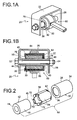
- an isolation assembly in accordance with one embodiment of the subject invention is generally shown at 20 in Figures 1A and 1B.
- the isolation assembly 20 is shown in a rest state in these Figures.
- the isolation assembly 20 is preferably for use with a vehicle having a frame portion 22.
- the frame portion 22 can be of any suitable design or configuration without deviating from the scope of the subject invention.
- the subject invention may be incorporated into different apparatuses and the subsequent discussion relating to a vehicle is but one contemplated environment for the invention.
- the isolation assembly 20 includes a collar 30 having a substantially continuous wall 28 defining a cavity.
- the collar 30 has a first flange 34 and a second flange 36, the purpose of which will be discussed in greater detail below.
- the collar 30, wall 28, and flanges 34, 36 may be formed of a single continuous piece of material, such as metal, or may be formed of separate components and welded together.
- the collar 30 also includes an aperture 40 with the continuous wall 28 surrounding the aperture 40.
- the aperture 40 is annular and the continuous wall 28 surrounding the aperture 40 is likewise annular.
- a carriage 42 having first 44 and second 46 end surfaces and a peripheral surface 48, is at least partially disposed within the cavity defined by the continuous wall 28.
- the carriage 42 is substantially tubular with an outer surface that is complementary in configuration to the annular wall 28.
- a fastener 50 has first 52 and second 54 ends with the fastener 50 adapted to support the carriage 42 relative to the frame portion 22.
- the fastener 50 is a bolt 50 with the first end 52 mounted to one end of the frame portion 22 and the second end 54 mounted to another end of the frame portion 22 by a nut 56.
- the fastener 50 at least partially extends through the carriage 42 and the aperture 40 in the collar 30 and the first flange 34.
- a sleeve 55 is provided between the fastener 50 and the carriage 42.
- the fastener 50 and sleeve 55 are tightened onto the frame portion 22 in such a manner so that the fastener 50 and sleeve 55 do not move during any movement of the collar 30.
- the carriage 42 is preferably mounted onto the sleeve 55 in such a manner as to limit the amount of movement of the carriage 42 relative to the sleeve 55.
- An insulator 58 is disposed between the carriage 42 and the wall 28 of the collar 30 for coupling the carriage 42 to the collar 30 and for isolating the carriage 42 and the fastener 50 from the collar 30.
- the insulator 58 in turn isolates the collar 30 from the and frame portion 22.
- the combination of the carriage 42, insulator 58, and collar 30 define an isolation sub-assembly 60.
- the isolation sub-assembly 60 can be manufactured as a separate unit and subsequently secured to the isolation assembly 20 by the bolt 50.
- the insulator 58 has a first portion 62 and a plurality of second portions 64. Broadly stated, the first portion 62 at least partially encapsulates one of the second end surface 46 and the peripheral surface 48 of the carriage 42.
- the second portions 64 are movable relative to the first portion 62 about a living hinge 66 to at least partially encapsulate the other of the peripheral surface 48 and second end surface 46 of the carriage 42.
- the insulator 58 therefore fully isolates the carriage 42 from the collar 30.
- the first portion 62 of the insulator 58 at least partially encapsulates the second end surface 46 of the carriage 42.
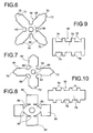
- the first portion 62 is complementary in configuration with the tubular carriage 42 such that in this embodiment the first portion 62 is circular, see Figures 5 and 6.
- the substantially annular wall 28 and substantially tubular carriage 42 define a substantially tubular insulator 58 that isolates the carriage 42 from the collar 30 equally in all directions.
- the first portion 62 also includes an aperture 68 that aligns with the aperture 40 in the collar 30 and the first flange 34.
- the first portion 62 of the insulator 58 is specifically disposed between the second end surface 46 of the carriage 42 and the first flange 34 to isolate the carriage 42 from the first flange 34.
- the second portions 64 encapsulate the peripheral surface 48 of the carriage 42.
- Each of the second portions 64 are substantially the same length and extend the same distance from the first portion 62 such that the peripheral surface 48 of the carriage 42 is equally encapsulated.
- each of the second portions 64 are also substantially the same width.
- the insulator 58 includes four substantially rectangular second portions 64 extending from the first portion 62 with the second portions 64 being positioned equidistantly around the first portion 62 to fully encapsulate the peripheral surface 48 of the carriage 42.
- Each of the second portions 64 can be identical.
- the insulator 58 also includes a plurality of neck portions defining the living hinges 66 with the neck portions being narrower than the first 62 and second 64 portions.
- the insulator 58 also includes a plurality of third portions 70 that are movable relative to the first 62 and second 64 portions about a second living hinge 72.
- the third portions 70 at least partially encapsulate the first end surface 44 of the carriage 42 such that the third portions 70 are disposed between the first end surface 44 of the carriage 42 and the second flange 36 to isolate the carriage 42 from the second flange 36.
- one of the third portions 70 extends from each of the second portions 64.
- the third portions 70 are formed as semi-circular tabs.
- the first 62, second 64, and third 70 portions of the insulator 58 are formed of a common homogeneous material. More preferably, the common homogeneous material is further defined as micro-cellular polyurethane. As discussed in the background section, micro-cellular polyurethane is difficult and expensive to manufacture into three-dimensional shapes. As such, the insulator 58 of the subject invention includes the first 62, second 64, and third 70 portions that can be manufactured as a planar component and then manipulated into a three-dimensional shape.
- Figure 7 illustrates an alternative embodiment of the insulator 58 that includes an oval first portion 62.
- the remaining aspects of this alternative insulator 58 are substantially the same as the embodiment of Figures 2-6.
- this alternative insulator 58 also includes four second portions 64, similar neck portions defining living hinges 66, and a third portion 70 extending from each of the second portions 64.
- Figure 8 illustrates another alternative embodiment of the insulator 58 that includes an oval first portion 62 with slightly different configurations for the neck portions/living hinges 66 and second portions 64. Further, the third portions 70 are removed.
- the insulator 58 is of a significantly different configuration.
- these insulators 58 include a first portion 74 encapsulating the peripheral surface 48 of the carriage 42.
- the first portion 74 is substantially rectangular and wraps around the peripheral surface 48 of the carriage 42.
- the insulator 58 also includes second portions 76 that at least partially encapsulate the second end surface 46 of the carriage 42.
- Each of the second portions 76 are substantially the same size and are equidistantly spaced along the rectangular first portion 72.
- each of the second portions 76 are substantially the same length and extend the same distance from the first portion 72.
- each of the second portions 76 are substantially the same width such that each of the second portions 76 are preferably identical.
- the second portions 76 of the insulator 58 are designed to be disposed between the second end surface 46 of the carriage 42 and the first flange 34 of the collar 30 to isolate the carriage 42 from the first flange 34.
- the insulators 58 of the embodiments shown in Figures 9 and 10 also include a plurality of third portions 78 that are movable relative to the first 74 and second 76 portions about a second living hinge. These third portions 78 at least partially encapsulate the first end surface 44 of the carriage 42 such that the third portions 78 are disposed between the first end surface 44 of the carriage 42 and the second flange 36 of the collar 30 to isolate the carriage 42 from the second flange 36.
- the third portions 78 each extend from the first portion 74 in an opposite direction from the second portions 76. As with the second portions 76, each of the third portions 78 are substantially the same size and are equidistantly spaced along the rectangular first portion 74.
- Each of the third portions 78 are also substantially the same length and extend the same distance from the first portion 74. Further, each of the third portions 78 are substantially the same width such that each of the third portions 78 are preferably identical.
- the rectangular first portion 74 ends at the outer most second 76 and third portions 78.
- the rectangular first portion 74 extends beyond the second 76 and third portions 78.
- the isolation assembly 20 shown in these Figures is known as a body mount.
- a support plate 26 is provided with the isolation sub-assembly 60 abutting the support plate 26.
- the support plate 26 has a pair of appendages 32 that provide a mounting point such that the support plate 26 and isolation sub-assembly 60 can be mounted to the frame portion 22 of the vehicle.
- the plate 26, isolation sub-assembly 60, and frame portion 22 therefore move as a single unit.
- This embodiment further includes a bushing 61 that is included to isolate the frame portion 22 from a vehicle body 24.
- the bushing 61 illustrated is formed of a rubber material and has a donut-like configuration. Bushings of this type and configuration are well known in the art and will not be discussed in any greater detail.
- the isolation assembly 20 of Figures 11 and 12 has some common features to the isolation assembly 20 of Figure 1.
- the primary difference is in the configuration of the collar 30 and insulator 58.
- the collar 30 is further defined as an open cup having a continuous wall 28 extending between a top flange 80 and an open bottom 82.
- the top flange 80 includes the aperture 40 aligned with an aperture 38 of the support plate 26.
- the apertures 38, 40 are annular and the continuous wall 28 surrounding the apertures 38, 40 is likewise annular.
- This embodiment also includes a similar carriage 42, having first 44 and second 46 end surfaces and a peripheral surface 48, that is at least partially disposed within the cavity defined by the continuous wall 28.
- the carriage 42 is displaceable relative to the collar 30 along a vertical line of travel and is also displaceable relative to the collar 30 along a lateral line of travel.
- a fastener 50 has first 52 and second 54 ends with the first end 52 of the fastener 50 abutting the first end surface 44 of the carriage 42.
- the second end 54 of the fastener 50 is mounted to the vehicle body 24 by a nut 56.
- the insulator 58 of this embodiment has an alternative configuration, such as the one shown in Figure 8, in which the third portions are removed.
- the open collar 30 does not have a second flange such that it is not necessary to have a third portion.
- the insulator 58 may extend beyond the first end surface 44 of the carriage 42 as shown. Preferably the insulator 58 will not extend beyond the open bottom 82, i.e., the length of the open collar 30.
- the insulator 58 is disposed between the carriage 42 and the wall 28 of the collar 30 for coupling the carriage 42 to the collar 30 and for isolating the carriage 42 and the fastener 50 from the collar 30.
- the combination of the carriage 42, insulator 58, and collar 30 define an isolation sub-assembly 60.
- the isolation sub-assembly 60 can be manufactured as a separate unit and subsequently secured to the isolation assembly 20 by the bolt 50.
- the insulator 58 shown in Figures 11 and 12 also has a first portion 62 and a plurality of second portions 64.
- the first portion 62 at least partially encapsulates one of the second end surface 46 and the peripheral surface 48 of the carriage 42.
- the second portions 64 are movable relative to the first portion 62 about a living hinge 66 to at least partially encapsulate the other of the peripheral surface 48 and second end surface 46 of the carriage 42.
- the specific insulator 58 shown in Figures 11 and 12 has the first portion 62 of the insulator 58 at least partially encapsulating the second end surface 46 of the carriage 42.
- the second portions 64 encapsulate the peripheral surface 48 of the carriage 42.
- Each of the second portions 64 are substantially the same length and extend the same distance from the first portion 62 such that the peripheral surface 48 of the carriage 42 is equally encapsulated.
- each of the second portions 64 are also substantially the same width.
- the insulator 58 includes four substantially rectangular second portions 64 extending from the first portion 62 with the second portions 64 being positioned equidistantly around the first portion 62 to fully encapsulate the peripheral surface 48 of the carriage 42.
- Each of the second portions 64 can be identical.
- the first 62 and second 64 portions of the insulator 58 are formed of a common homogeneous material. More preferably, the common homogeneous material is further defined as micro-cellular polyurethane.
- the insulator 58 of this embodiment could also be the type disclosed in Figures 9 and 10.
- the first portion 74 of the insulator 58 could encapsulate the peripheral surface 48 of the carriage 42.
- the first portion 74 could be substantially rectangular and could wrap around the peripheral surface 48 of the carriage 42.
- the second portions 76 would at least partially encapsulate the second end surface 46 of the carriage 42.
- Each of the second portions 76 are preferably of substantially the same size and are equidistantly spaced along the rectangular first portion 74.
- each of the second portions 76 are substantially the same length and extend the same distance from the first portion 74.
- each of the second portions 76 are substantially the same width such that each of the second portions 76 are preferably identical.
- the second portions 76 of the insulator 58 are designed to be disposed between the second end surface 46 of the carriage 42 and the first flange 34 to isolate the carriage 42 from the first flange 34.
- the third portions shown in Figures 9 and 10 would be eliminated if this type of insulator 58 was incorporated into the isolation sub-assembly 60 of Figures 11 and 12.
- each of the unique insulators 58 disclosed above are preferably installed into the isolation assembly 20 in a unique manner.
- the subject invention includes a method of installing the insulator 58 within the isolation assembly 20.
- the method comprises the steps of positioning the insulator 58 about the carriage 42.
- the carriage 42 and insulator 58 are at least partially inserted within the cavity to couple the carriage 42 to the collar 30 through the insulator 58 such that the carriage 42 is isolated from the collar 30.
- the fastener 50 is inserted through the carriage 42. In the embodiment of Figures 11 and 12, the first end 52 of the fastener 50 abuts with the first end surface 44 of the carriage 42.
- the fastener 50 is then secured such that the carriage 42 remains inserted within the cavity.
- the fastener 50 is secured between opposing ends of the frame portion 22.
- the second end 54 of the fastener 50 is secured to the vehicle body 24 by the nut 56.
- the fastener 50 preferably passes through the carriage 42, the aperture 68 in the insulator 58, and the aperture 40 in the collar 30 to extend outwardly for interengagement with the nut 56.
- the step of positioning the insulator 58 about the carriage 42 is further defined as at least partially encapsulating one of the second end surface 46 and the peripheral surface 48 of the carriage 42 with the first portion 62, 74, moving the second portions 64, 76 relative to the first portions 62, 74 about the living hinges 66, and at least partially encapsulating the other of the peripheral surface 48 and second end surface 46 of the carriage 42 with the second portions 64, 76 to adequately isolate the carriage 42 from the collar 30.
- the step of positioning the insulator 58 about the carriage 42 is performed before the step of inserting the carriage 42 and insulator 58 within the cavity. This order of steps simplifies the assembly procedure.
- the step of positioning the insulator 58 about the carriage 42 is further defined as at least partially encapsulating the second end surface 46 of the carriage 42 with the first portion 62, moving the second portions 64 relative to the first portions 62 about the living hinges 66, and encapsulating the peripheral surface 48 of the carriage 42 with the second portions 64 to adequately isolate the carriage 42 from the collar 30.
- the step of positioning the insulator 58 about the carriage 42 can be further defined as at least partially encapsulating the first end surface 44 of the carriage 42 with the third portions 70.
- the step of positioning the insulator 58 about the carriage 42 could be defined as encapsulating the peripheral surface 48 of the carriage 42 with the first portion 74, moving the second portions 76 relative to the first portions 74 about the living hinges, and at least partially encapsulating the second end surface 46 of the carriage 42 with the second portions 76 to adequately isolate the carriage 42 from the collar 30.
- the step of positioning the insulator 58 about the carriage 42 is even further defined as at least partially encapsulating the first end surface 44 of the carriage 42 with the third portions 78.
- This alternative method requires a slightly different installation procedure.
- the step of positioning the insulator 58 about the carriage 42 is further defined as wrapping the peripheral surface 48 of the carriage 42 with the first portion 74.
Landscapes
- Engineering & Computer Science (AREA)
- Mechanical Engineering (AREA)
- Vibration Prevention Devices (AREA)
- Support Of The Bearing (AREA)
- Springs (AREA)
- Motor Or Generator Frames (AREA)
Applications Claiming Priority (2)
| Application Number | Priority Date | Filing Date | Title |
|---|---|---|---|
| US10/744,521 US7219883B2 (en) | 2003-12-23 | 2003-12-23 | Isolation assembly for a vehicle suspension component |
| US744521 | 2003-12-23 |
Publications (3)
| Publication Number | Publication Date |
|---|---|
| EP1547830A2 true EP1547830A2 (de) | 2005-06-29 |
| EP1547830A3 EP1547830A3 (de) | 2005-08-17 |
| EP1547830B1 EP1547830B1 (de) | 2010-09-08 |
Family
ID=34552851
Family Applications (1)
| Application Number | Title | Priority Date | Filing Date |
|---|---|---|---|
| EP04029023A Expired - Lifetime EP1547830B1 (de) | 2003-12-23 | 2004-12-08 | Buchsenlager für Fahrwerksteile in Kraftfahrzeugen |
Country Status (4)
| Country | Link |
|---|---|
| US (1) | US7219883B2 (de) |
| EP (1) | EP1547830B1 (de) |
| AT (1) | ATE480416T1 (de) |
| DE (1) | DE602004029002D1 (de) |
Families Citing this family (6)
| Publication number | Priority date | Publication date | Assignee | Title |
|---|---|---|---|---|
| FR2881496B1 (fr) * | 2005-02-02 | 2007-04-13 | Bosch Gmbh Robert | Dispositif anti-vibratoire et structure comportant un tel dispositif |
| WO2006119040A1 (en) * | 2005-04-29 | 2006-11-09 | Hendrickson International Corporation | Heavy-duty vehicle axle/suspension system |
| US20070222127A1 (en) * | 2006-03-23 | 2007-09-27 | Landon Ball | Threaded Plate Single Shear Mount Shock Absorber/Strut Mount |
| US20080036166A1 (en) * | 2006-08-14 | 2008-02-14 | Meritor Suspension Suystems Company, Us | Self-locking sleeve for stabilizer bar |
| DE102015117349A1 (de) * | 2015-10-12 | 2017-04-13 | Benteler Automobiltechnik Gmbh | Befestigungsschäkel zur befestigung einer blattfeder an einem fahrzeugaufbau |
| JP2025119148A (ja) * | 2024-02-01 | 2025-08-14 | トヨタ自動車株式会社 | ダブルウィッシュボーン式緩衝装置のアッパアーム取り付け構造 |
Family Cites Families (10)
| Publication number | Priority date | Publication date | Assignee | Title |
|---|---|---|---|---|
| US2675283A (en) | 1949-11-19 | 1954-04-13 | John B Thomson | Bearing |
| FR2657564B1 (fr) * | 1990-02-01 | 1992-04-10 | Peugeot | Palier elastique a glissement interne. |
| DE4309425C1 (de) * | 1993-03-24 | 1994-06-01 | Lemfoerder Metallwaren Ag | Gummilager für den Mittelzapfen einer Blattfederaufhängung in einem Kraftfahrzeug |
| DE4415599A1 (de) * | 1994-05-04 | 1995-08-10 | Daimler Benz Ag | Lagerung eines Torsionsstabes eines Stabilisators einer Fahrzeugachse |
| US5820115A (en) * | 1995-06-13 | 1998-10-13 | Btr Antivibration Systems, Inc. | Film slipper bushing assembly |
| DE19709669C1 (de) * | 1997-03-11 | 1998-06-18 | Mannesmann Boge Gmbh | Gummilager, insbesondere für die Lagerung eines Stabilisatorstabes an einem Kraftfahrzeug |
| FR2768661B1 (fr) | 1997-09-24 | 1999-12-10 | Allevard Ressorts Automobile | Palier de barre anti-devers a glissement sans cheminement applicable aux vehicules |
| DE10116053A1 (de) | 2001-03-30 | 2002-10-10 | Zf Boge Gmbh | Gummilager für Fahrwerksteile in Kraftfahrzeugen |
| US6619639B1 (en) | 2001-12-21 | 2003-09-16 | Atro Engineered Systems, Inc. | Low fiction rotating bushing, particularly for heavy vehicle lift axle |
| US6513801B1 (en) * | 2002-07-24 | 2003-02-04 | The Pullman Company | Hinged/split reinforced clam shell bushing |
-
2003
- 2003-12-23 US US10/744,521 patent/US7219883B2/en not_active Expired - Fee Related
-
2004
- 2004-12-08 AT AT04029023T patent/ATE480416T1/de not_active IP Right Cessation
- 2004-12-08 DE DE602004029002T patent/DE602004029002D1/de not_active Expired - Lifetime
- 2004-12-08 EP EP04029023A patent/EP1547830B1/de not_active Expired - Lifetime
Non-Patent Citations (1)
| Title |
|---|
| None |
Also Published As
| Publication number | Publication date |
|---|---|
| DE602004029002D1 (de) | 2010-10-21 |
| US7219883B2 (en) | 2007-05-22 |
| US20050134016A1 (en) | 2005-06-23 |
| EP1547830B1 (de) | 2010-09-08 |
| EP1547830A3 (de) | 2005-08-17 |
| ATE480416T1 (de) | 2010-09-15 |
Similar Documents
| Publication | Publication Date | Title |
|---|---|---|
| EP1547831A2 (de) | Oberes Federbeinstützlager für Radaufhängungen in einem Kraftfahrzeug | |
| US4936556A (en) | Liquid-sealed body mount | |
| CN101415960B (zh) | 用于机动车的径向活节以及用于制造这样的径向活节的方法 | |
| EP0479548B1 (de) | Stossdämpfendes Lager | |
| JP2001059547A (ja) | 振動減衰装置及びその製造方法 | |
| KR102073385B1 (ko) | 다단 코일 구조의 코어부재와 자기유변탄성체를 이용한 차량 서스펜션용 진동 절연 부시 | |
| US20080315473A1 (en) | Torque rod | |
| US8056888B2 (en) | Hydraulic bearing with biaxial damping | |
| EP1681180B1 (de) | Federbeinstützlager | |
| US7219883B2 (en) | Isolation assembly for a vehicle suspension component | |
| EP0992372B1 (de) | Fahrzeugaufhängungssystem | |
| US8998228B2 (en) | Steering attenuator assembly for motor vehicle | |
| US5193787A (en) | Sleeve and bushing assembly and method of manufacturing the same | |
| KR20170055573A (ko) | 차량용 마운팅 장치 | |
| US4854561A (en) | Elastic bushing filled with viscous fluid | |
| JPH08233030A (ja) | 連結ロッド | |
| US5855364A (en) | Hydraulic antivibration support and a motor vehicle subassembly including such a support | |
| US5277410A (en) | Upper support for suspension system having two outer rigid members, and method of manufacturing the same | |
| US10047820B2 (en) | Fluid-filled, vibration damping bushing assembly and method of manufacturing the same | |
| KR102496191B1 (ko) | 자동차용 변속기 마운트 | |
| JPH11170836A (ja) | ストラットマウント | |
| JPH08210409A (ja) | 防振支持装置 | |
| KR100363966B1 (ko) | 기어변환제어레버의설치에응용할수있는장치 | |
| JP2002274137A (ja) | サスペンションサポート | |
| JP2005106293A (ja) | 連結ロッド |
Legal Events
| Date | Code | Title | Description |
|---|---|---|---|
| PUAI | Public reference made under article 153(3) epc to a published international application that has entered the european phase |
Free format text: ORIGINAL CODE: 0009012 |
|
| AK | Designated contracting states |
Kind code of ref document: A2 Designated state(s): AT BE BG CH CY CZ DE DK EE ES FI FR GB GR HU IE IS IT LI LT LU MC NL PL PT RO SE SI SK TR |
|
| AX | Request for extension of the european patent |
Extension state: AL BA HR LV MK YU |
|
| PUAL | Search report despatched |
Free format text: ORIGINAL CODE: 0009013 |
|
| AK | Designated contracting states |
Kind code of ref document: A3 Designated state(s): AT BE BG CH CY CZ DE DK EE ES FI FR GB GR HU IE IS IT LI LT LU MC NL PL PT RO SE SI SK TR |
|
| AX | Request for extension of the european patent |
Extension state: AL BA HR LV MK YU |
|
| 17P | Request for examination filed |
Effective date: 20060217 |
|
| AKX | Designation fees paid |
Designated state(s): AT BE BG CH CY CZ DE DK EE ES FI FR GB GR HU IE IS IT LI LT LU MC NL PL PT RO SE SI SK TR |
|
| GRAP | Despatch of communication of intention to grant a patent |
Free format text: ORIGINAL CODE: EPIDOSNIGR1 |
|
| GRAS | Grant fee paid |
Free format text: ORIGINAL CODE: EPIDOSNIGR3 |
|
| GRAA | (expected) grant |
Free format text: ORIGINAL CODE: 0009210 |
|
| AK | Designated contracting states |
Kind code of ref document: B1 Designated state(s): AT BE BG CH CY CZ DE DK EE ES FI FR GB GR HU IE IS IT LI LT LU MC NL PL PT RO SE SI SK TR |
|
| REG | Reference to a national code |
Ref country code: GB Ref legal event code: FG4D |
|
| REG | Reference to a national code |
Ref country code: CH Ref legal event code: EP |
|
| REG | Reference to a national code |
Ref country code: IE Ref legal event code: FG4D |
|
| REF | Corresponds to: |
Ref document number: 602004029002 Country of ref document: DE Date of ref document: 20101021 Kind code of ref document: P |
|
| REG | Reference to a national code |
Ref country code: NL Ref legal event code: VDEP Effective date: 20100908 |
|
| PG25 | Lapsed in a contracting state [announced via postgrant information from national office to epo] |
Ref country code: FI Free format text: LAPSE BECAUSE OF FAILURE TO SUBMIT A TRANSLATION OF THE DESCRIPTION OR TO PAY THE FEE WITHIN THE PRESCRIBED TIME-LIMIT Effective date: 20100908 Ref country code: LT Free format text: LAPSE BECAUSE OF FAILURE TO SUBMIT A TRANSLATION OF THE DESCRIPTION OR TO PAY THE FEE WITHIN THE PRESCRIBED TIME-LIMIT Effective date: 20100908 Ref country code: AT Free format text: LAPSE BECAUSE OF FAILURE TO SUBMIT A TRANSLATION OF THE DESCRIPTION OR TO PAY THE FEE WITHIN THE PRESCRIBED TIME-LIMIT Effective date: 20100908 |
|
| LTIE | Lt: invalidation of european patent or patent extension |
Effective date: 20100908 |
|
| PG25 | Lapsed in a contracting state [announced via postgrant information from national office to epo] |
Ref country code: CY Free format text: LAPSE BECAUSE OF FAILURE TO SUBMIT A TRANSLATION OF THE DESCRIPTION OR TO PAY THE FEE WITHIN THE PRESCRIBED TIME-LIMIT Effective date: 20100908 Ref country code: SI Free format text: LAPSE BECAUSE OF FAILURE TO SUBMIT A TRANSLATION OF THE DESCRIPTION OR TO PAY THE FEE WITHIN THE PRESCRIBED TIME-LIMIT Effective date: 20100908 Ref country code: PL Free format text: LAPSE BECAUSE OF FAILURE TO SUBMIT A TRANSLATION OF THE DESCRIPTION OR TO PAY THE FEE WITHIN THE PRESCRIBED TIME-LIMIT Effective date: 20100908 |
|
| PG25 | Lapsed in a contracting state [announced via postgrant information from national office to epo] |
Ref country code: GR Free format text: LAPSE BECAUSE OF FAILURE TO SUBMIT A TRANSLATION OF THE DESCRIPTION OR TO PAY THE FEE WITHIN THE PRESCRIBED TIME-LIMIT Effective date: 20101209 Ref country code: SE Free format text: LAPSE BECAUSE OF FAILURE TO SUBMIT A TRANSLATION OF THE DESCRIPTION OR TO PAY THE FEE WITHIN THE PRESCRIBED TIME-LIMIT Effective date: 20100908 Ref country code: NL Free format text: LAPSE BECAUSE OF FAILURE TO SUBMIT A TRANSLATION OF THE DESCRIPTION OR TO PAY THE FEE WITHIN THE PRESCRIBED TIME-LIMIT Effective date: 20100908 |
|
| PG25 | Lapsed in a contracting state [announced via postgrant information from national office to epo] |
Ref country code: IT Free format text: LAPSE BECAUSE OF FAILURE TO SUBMIT A TRANSLATION OF THE DESCRIPTION OR TO PAY THE FEE WITHIN THE PRESCRIBED TIME-LIMIT Effective date: 20100908 Ref country code: RO Free format text: LAPSE BECAUSE OF FAILURE TO SUBMIT A TRANSLATION OF THE DESCRIPTION OR TO PAY THE FEE WITHIN THE PRESCRIBED TIME-LIMIT Effective date: 20100908 Ref country code: PT Free format text: LAPSE BECAUSE OF FAILURE TO SUBMIT A TRANSLATION OF THE DESCRIPTION OR TO PAY THE FEE WITHIN THE PRESCRIBED TIME-LIMIT Effective date: 20110110 Ref country code: CZ Free format text: LAPSE BECAUSE OF FAILURE TO SUBMIT A TRANSLATION OF THE DESCRIPTION OR TO PAY THE FEE WITHIN THE PRESCRIBED TIME-LIMIT Effective date: 20100908 Ref country code: SK Free format text: LAPSE BECAUSE OF FAILURE TO SUBMIT A TRANSLATION OF THE DESCRIPTION OR TO PAY THE FEE WITHIN THE PRESCRIBED TIME-LIMIT Effective date: 20100908 Ref country code: EE Free format text: LAPSE BECAUSE OF FAILURE TO SUBMIT A TRANSLATION OF THE DESCRIPTION OR TO PAY THE FEE WITHIN THE PRESCRIBED TIME-LIMIT Effective date: 20100908 Ref country code: IS Free format text: LAPSE BECAUSE OF FAILURE TO SUBMIT A TRANSLATION OF THE DESCRIPTION OR TO PAY THE FEE WITHIN THE PRESCRIBED TIME-LIMIT Effective date: 20110108 |
|
| PG25 | Lapsed in a contracting state [announced via postgrant information from national office to epo] |
Ref country code: BE Free format text: LAPSE BECAUSE OF FAILURE TO SUBMIT A TRANSLATION OF THE DESCRIPTION OR TO PAY THE FEE WITHIN THE PRESCRIBED TIME-LIMIT Effective date: 20100908 Ref country code: ES Free format text: LAPSE BECAUSE OF FAILURE TO SUBMIT A TRANSLATION OF THE DESCRIPTION OR TO PAY THE FEE WITHIN THE PRESCRIBED TIME-LIMIT Effective date: 20101219 |
|
| PLBE | No opposition filed within time limit |
Free format text: ORIGINAL CODE: 0009261 |
|
| STAA | Information on the status of an ep patent application or granted ep patent |
Free format text: STATUS: NO OPPOSITION FILED WITHIN TIME LIMIT |
|
| PG25 | Lapsed in a contracting state [announced via postgrant information from national office to epo] |
Ref country code: MC Free format text: LAPSE BECAUSE OF NON-PAYMENT OF DUE FEES Effective date: 20101231 |
|
| REG | Reference to a national code |
Ref country code: CH Ref legal event code: PL |
|
| 26N | No opposition filed |
Effective date: 20110609 |
|
| GBPC | Gb: european patent ceased through non-payment of renewal fee |
Effective date: 20101208 |
|
| PG25 | Lapsed in a contracting state [announced via postgrant information from national office to epo] |
Ref country code: DK Free format text: LAPSE BECAUSE OF FAILURE TO SUBMIT A TRANSLATION OF THE DESCRIPTION OR TO PAY THE FEE WITHIN THE PRESCRIBED TIME-LIMIT Effective date: 20100908 |
|
| REG | Reference to a national code |
Ref country code: FR Ref legal event code: ST Effective date: 20110831 |
|
| REG | Reference to a national code |
Ref country code: DE Ref legal event code: R097 Ref document number: 602004029002 Country of ref document: DE Effective date: 20110609 |
|
| PG25 | Lapsed in a contracting state [announced via postgrant information from national office to epo] |
Ref country code: IE Free format text: LAPSE BECAUSE OF NON-PAYMENT OF DUE FEES Effective date: 20101208 Ref country code: CH Free format text: LAPSE BECAUSE OF NON-PAYMENT OF DUE FEES Effective date: 20101231 Ref country code: LI Free format text: LAPSE BECAUSE OF NON-PAYMENT OF DUE FEES Effective date: 20101231 Ref country code: FR Free format text: LAPSE BECAUSE OF NON-PAYMENT OF DUE FEES Effective date: 20110103 |
|
| PG25 | Lapsed in a contracting state [announced via postgrant information from national office to epo] |
Ref country code: GB Free format text: LAPSE BECAUSE OF NON-PAYMENT OF DUE FEES Effective date: 20101208 |
|
| PG25 | Lapsed in a contracting state [announced via postgrant information from national office to epo] |
Ref country code: LU Free format text: LAPSE BECAUSE OF NON-PAYMENT OF DUE FEES Effective date: 20101208 Ref country code: BG Free format text: LAPSE BECAUSE OF FAILURE TO SUBMIT A TRANSLATION OF THE DESCRIPTION OR TO PAY THE FEE WITHIN THE PRESCRIBED TIME-LIMIT Effective date: 20100908 Ref country code: HU Free format text: LAPSE BECAUSE OF FAILURE TO SUBMIT A TRANSLATION OF THE DESCRIPTION OR TO PAY THE FEE WITHIN THE PRESCRIBED TIME-LIMIT Effective date: 20110309 |
|
| PG25 | Lapsed in a contracting state [announced via postgrant information from national office to epo] |
Ref country code: TR Free format text: LAPSE BECAUSE OF FAILURE TO SUBMIT A TRANSLATION OF THE DESCRIPTION OR TO PAY THE FEE WITHIN THE PRESCRIBED TIME-LIMIT Effective date: 20100908 |
|
| PG25 | Lapsed in a contracting state [announced via postgrant information from national office to epo] |
Ref country code: BG Free format text: LAPSE BECAUSE OF FAILURE TO SUBMIT A TRANSLATION OF THE DESCRIPTION OR TO PAY THE FEE WITHIN THE PRESCRIBED TIME-LIMIT Effective date: 20101208 |
|
| PGFP | Annual fee paid to national office [announced via postgrant information from national office to epo] |
Ref country code: DE Payment date: 20140228 Year of fee payment: 10 |
|
| REG | Reference to a national code |
Ref country code: DE Ref legal event code: R119 Ref document number: 602004029002 Country of ref document: DE |
|
| PG25 | Lapsed in a contracting state [announced via postgrant information from national office to epo] |
Ref country code: DE Free format text: LAPSE BECAUSE OF NON-PAYMENT OF DUE FEES Effective date: 20150701 |