EP1547824B1 - Assemblage d'antenne à haut allongement et procédé pour un pneumatique - Google Patents
Assemblage d'antenne à haut allongement et procédé pour un pneumatique Download PDFInfo
- Publication number
- EP1547824B1 EP1547824B1 EP04106688A EP04106688A EP1547824B1 EP 1547824 B1 EP1547824 B1 EP 1547824B1 EP 04106688 A EP04106688 A EP 04106688A EP 04106688 A EP04106688 A EP 04106688A EP 1547824 B1 EP1547824 B1 EP 1547824B1
- Authority
- EP
- European Patent Office
- Prior art keywords
- antenna
- tire
- textile fabric
- strip
- carrier strip
- Prior art date
- Legal status (The legal status is an assumption and is not a legal conclusion. Google has not performed a legal analysis and makes no representation as to the accuracy of the status listed.)
- Expired - Lifetime
Links
- 238000000034 method Methods 0.000 title claims description 18
- 239000004744 fabric Substances 0.000 claims description 12
- 239000004753 textile Substances 0.000 claims description 10
- 239000013013 elastic material Substances 0.000 claims description 5
- 210000004177 elastic tissue Anatomy 0.000 claims description 4
- 238000009958 sewing Methods 0.000 claims description 2
- 239000002657 fibrous material Substances 0.000 claims 3
- 238000009941 weaving Methods 0.000 claims 1
- 239000000758 substrate Substances 0.000 description 21
- 238000004519 manufacturing process Methods 0.000 description 15
- 239000000463 material Substances 0.000 description 15
- 229920002334 Spandex Polymers 0.000 description 5
- 238000012544 monitoring process Methods 0.000 description 5
- 229910000831 Steel Inorganic materials 0.000 description 4
- 239000000853 adhesive Substances 0.000 description 4
- 230000001070 adhesive effect Effects 0.000 description 4
- 239000004759 spandex Substances 0.000 description 4
- 239000010959 steel Substances 0.000 description 4
- 238000004891 communication Methods 0.000 description 3
- 230000006378 damage Effects 0.000 description 3
- 239000000835 fiber Substances 0.000 description 3
- 238000010348 incorporation Methods 0.000 description 3
- 238000011084 recovery Methods 0.000 description 3
- RYGMFSIKBFXOCR-UHFFFAOYSA-N Copper Chemical compound [Cu] RYGMFSIKBFXOCR-UHFFFAOYSA-N 0.000 description 2
- 229910000881 Cu alloy Inorganic materials 0.000 description 2
- 229910052782 aluminium Inorganic materials 0.000 description 2
- XAGFODPZIPBFFR-UHFFFAOYSA-N aluminium Chemical compound [Al] XAGFODPZIPBFFR-UHFFFAOYSA-N 0.000 description 2
- 239000004020 conductor Substances 0.000 description 2
- 238000010276 construction Methods 0.000 description 2
- 229910052802 copper Inorganic materials 0.000 description 2
- 239000010949 copper Substances 0.000 description 2
- 239000004033 plastic Substances 0.000 description 2
- 239000011324 bead Substances 0.000 description 1
- 239000002131 composite material Substances 0.000 description 1
- 230000007812 deficiency Effects 0.000 description 1
- 230000001419 dependent effect Effects 0.000 description 1
- 230000007257 malfunction Effects 0.000 description 1
- 229910052751 metal Inorganic materials 0.000 description 1
- 239000002184 metal Substances 0.000 description 1
- 230000002093 peripheral effect Effects 0.000 description 1
- 238000007493 shaping process Methods 0.000 description 1
Images
Classifications
-
- B—PERFORMING OPERATIONS; TRANSPORTING
- B60—VEHICLES IN GENERAL
- B60C—VEHICLE TYRES; TYRE INFLATION; TYRE CHANGING; CONNECTING VALVES TO INFLATABLE ELASTIC BODIES IN GENERAL; DEVICES OR ARRANGEMENTS RELATED TO TYRES
- B60C23/00—Devices for measuring, signalling, controlling, or distributing tyre pressure or temperature, specially adapted for mounting on vehicles; Arrangement of tyre inflating devices on vehicles, e.g. of pumps or of tanks; Tyre cooling arrangements
- B60C23/02—Signalling devices actuated by tyre pressure
- B60C23/04—Signalling devices actuated by tyre pressure mounted on the wheel or tyre
- B60C23/0491—Constructional details of means for attaching the control device
- B60C23/0493—Constructional details of means for attaching the control device for attachment on the tyre
-
- H—ELECTRICITY
- H01—ELECTRIC ELEMENTS
- H01Q—ANTENNAS, i.e. RADIO AERIALS
- H01Q1/00—Details of, or arrangements associated with, antennas
- H01Q1/12—Supports; Mounting means
- H01Q1/22—Supports; Mounting means by structural association with other equipment or articles
- H01Q1/2208—Supports; Mounting means by structural association with other equipment or articles associated with components used in interrogation type services, i.e. in systems for information exchange between an interrogator/reader and a tag/transponder, e.g. in Radio Frequency Identification [RFID] systems
- H01Q1/2241—Supports; Mounting means by structural association with other equipment or articles associated with components used in interrogation type services, i.e. in systems for information exchange between an interrogator/reader and a tag/transponder, e.g. in Radio Frequency Identification [RFID] systems used in or for vehicle tyres
-
- B—PERFORMING OPERATIONS; TRANSPORTING
- B29—WORKING OF PLASTICS; WORKING OF SUBSTANCES IN A PLASTIC STATE IN GENERAL
- B29D—PRODUCING PARTICULAR ARTICLES FROM PLASTICS OR FROM SUBSTANCES IN A PLASTIC STATE
- B29D30/00—Producing pneumatic or solid tyres or parts thereof
- B29D30/0061—Accessories, details or auxiliary operations not otherwise provided for
- B29D2030/0072—Attaching fasteners to tyres, e.g. patches, in order to connect devices to tyres
-
- B—PERFORMING OPERATIONS; TRANSPORTING
- B29—WORKING OF PLASTICS; WORKING OF SUBSTANCES IN A PLASTIC STATE IN GENERAL
- B29D—PRODUCING PARTICULAR ARTICLES FROM PLASTICS OR FROM SUBSTANCES IN A PLASTIC STATE
- B29D30/00—Producing pneumatic or solid tyres or parts thereof
- B29D30/0061—Accessories, details or auxiliary operations not otherwise provided for
- B29D2030/0077—Directly attaching monitoring devices to tyres before or after vulcanization, e.g. microchips
Definitions
- the invention relates generally to an apparatus, including an antenna and a transponder, for a tire pressure monitoring system and, more specifically, to an elastic annular apparatus for incorporation into a tire pressure monitoring system.
- annular apparatus including an antenna, for electronically transmitting tire or wheel identification or other data at radio frequency.
- the apparatus includes a radio-frequency transponder comprising an integrated circuit chip having data capacity at least sufficient to retain identification information for the tire or wheel.
- Other data such as the inflation pressure of the tire or the temperature of the tire or wheel at the transponder location, can be transmitted by the transponder along with the identification data.
- the antenna comprises a wire or strands of wire formed into a loop that may be sheathed in an extruded covering formed from a suitable material such as plastic.
- the plastic sheath in combination with the antenna form a unitary body that may be affixed to a green tire in a pre-build assembly process or attached to a finished tire in a post-cure operation. While the antenna and transponder may be incorporated into a tire during "pre-cure" manufacture, in practice it is very difficult to do this.
- Both radial ply and bias ply tires undergo a substantial diametric enlargement during the course of manufacture.
- Bias ply tires are expanded diametrically when inserted into a curing press, which typically has a bladder that forces the green tire into the toroidal shape of the mold enclosing it.
- Radial ply tires undergo diametric expansion during the tire building or shaping process and a further diametric expansion during the course of curing. Any annular antenna and the electronic circuitry associated therewith built into the tire must be able to maintain structural integrity and the mechanical connection between the antenna and transponder package during the diametric enlargement of the tire during its manufacture.
- any detected malfunction in the antenna, transponder, or antenna to transponder connection that cannot be repaired destroys the utility of the tire and may necessitate a scrapping of the tire.
- placement of an annular antenna-transponder assembly into a tire during its manufacture carries risk that subsequent failure or breakage of assembly components will necessitate the destruction of the otherwise suitable host tire.
- loop antennas and the electronics associated therewith are subjected to substantial compressive strain and at the sidewall a high strain amplitude. Such locations represent high load and deformation to regions of the tire. Consequently, antenna, transponders, and the connections therebetween in such locations are prone to breakage and mechanical or electrical failure.
- the antenna apparatus must provide sufficient structural integrity to withstand the stresses attendant tire building processes and post-manufacture use on a vehicle. Moreover, the antenna apparatus ideally will maintain its optimal, intended configuration and shape throughout the tire build operation and subsequent use on a vehicle. Since the performance of the tire pressure monitoring system is dependent upon efficient communication between the tire electronics and a remote reader via the antenna, maintaining the antenna in an optimal configuration is highly desirable.
- WO-A-99/29525 discloses a tire having an antenna assembly incorporated therein and a method for mounting an annular antenna to a tire according to the preamble of claim 1 and 5 respectively.
- the subject invention overcomes the deficiencies in known antenna systems and methods for tire monitoring systems by utilizing an elastic substrate in combination with an antenna wire(s) according to claim 1.
- the antenna cable can be wrapped around or otherwise applied to the elastic substrate, preferably in a wave, helical or sinusoidal configuration.
- the substrate When subjected to forces of external origin, the substrate can elongate while the antenna wire straightens. Upon release from the influence of such forces, residual elastomeric spring forces within the elastic substrate returns the substrate and the antenna cable carried thereby back to its original, optimal configuration.
- the pitch of the antenna material on the substrate may be customized to suit the needs of the particular tire and communication system.
- the substrate comprises a tube of elastic material around which the antenna is wound.
- the antenna may be formed to zigzag across an elastic substrate in strip form.
- the antenna may be attached to the substrate by a sewing procedure or by adhesive application to the substrate.
- Such an assembly may be incorporated into a tire during the tire manufacturing process or attached to the tire by adhesives or other known methods in a post-manufacture attachment procedure.
- the elastic substrate protects the integrity of the antenna wire; allows the unitary assembly to be conveniently transported and inventoried; restores the antenna back into an intended optimal configuration after allowing for a dissipation of mechanical energy through elongation of the antenna and substrate; and maintains an optimal location of the antenna annular assembly within a tire cavity.
- a tire pressure monitoring system typically consists of a transponder having one or more sensors.
- the transponder and associated electronics are housed within a package.
- a transponder In order to send or receive RF signals, a transponder must have an antenna.
- the antenna is preferably annular in configuration in the subject invention but may have alternative shapes if desired.
- the antenna may either be incorporated into the tire during manufacture or affixed to the tire by way of a post manufacture procedure.
- an "annular antenna” may be circular, oblong, symmetrical, or asymmetrical without departing from the subject inventive principles.
- the preferred configuration of the antenna is circular and sized to overlap the tire sidewall region to which it attaches.
- the preferred location is the sidewall, but upper sidewall or crown placement is also possible.
- the antenna may comprise a single wire or a plurality of strands.
- Various commercially available transponders, sensors, and other electrical devices deployed in combination with an annular antenna formed from conventional conductive materials
- Acceptable materials for the antenna wire include steel, aluminum, copper, copper alloys or other electrically conducting wire.
- the wire diameter is not generally considered critical for operation as an antenna for a transponder.
- stranded steel wire consisting of multiple strands of fine wire is preferred.
- Other wire options available include ribbon cable, ribbon conductors over organic fibers, flexible circuits, conductive film, conductive rubber, etc.
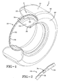
- a preferred embodiment 10 of the subject invention is shown deployed within a tire 12.
- the tire 12 is formed from conventional materials such as rubber or rubber composites by conventional means and may comprise a radial ply or bias ply configuration.
- a typical tire 12 is configured having a tread 14, a shoulder 16, an annular sidewall 18, and a terminal bead 20.
- An inner liner 22 is formed and defines a tire cavity 24.
- the tire 12 is intended for mounted location upon an annular rim 26 having a peripheral rim flange and an outer rim flange surface 30.
- Rim 26 is conventionally configured and composed of a suitably strong metal such as steel.
- An annular antenna 32 is provided and, in the preferred embodiment, embodies a sinusoidal configuration.
- Antenna 32 may be alternatively configured into alternative patterns or comprise a straight wire(s) if desired and may be filament wire, or cord or stranded wire.
- Acceptable materials for the wire include steel, aluminum, copper, copper alloys or other electrically conducting wire.
- the wire diameter is not generally considered critical for operation as an antenna and multiple strands of fine wire is preferred.
- the sinusoidal, or zigzag form of antenna 32 provides flexibility and minimizes the risk of breakage during manufacture and use explained below.
- a transponder module 34 of the general type described above is provided and may include means for sensing tire parameters such as pressure and temperature.
- a carrier strip of material 36 formed preferably but not necessarily into the annular configuration shown.
- Carrier strip 36 is formed of electrically insulating, elastic material as will be described below.
- the apparatus 10 comprising antenna 32, transponder module 34, and carrier strip 36, in a unitary, generally circular, assembly that is readily transportable and handled for attachment to tire 12.
- the diameter of the apparatus assembly 10 is a function of the size of the tire 12 and the preferred attachment location thereon.
- the apparatus 10 is affixed to liner 22 of the tire 12 either during manufacture of the tire or, as preferable, in a post-manufacture assembly operation. Attachment may be by means of an adhesive or the apparatus may be embedded into the tire itself during manufacture.
- the carrier strip 36 represents an elastic substrate on which the antenna 32 is secured in one of a variety of attachment methods.
- the carrier strip 36 utilizes elasticized fibers, generically referred to herein as Spandex in the shape of a tube, strip, or other alternative geometries that will be obvious to those skilled in the art.
- the antenna cable 32 may be either a single wire or a strand of plural wires wrapped around carrier strip 36 in the form of a tube, or, alternatively zigzagged across the strip 36.
- the antenna 32 may, by way of example and without any intent to delimit the invention, be sewn into the elastic material or woven into the material.
- the antenna 32 is held by the carrier strip material in a preferred configuration that will optimize the communication performance of the antenna in the system.
- the carrier strip 36 so composed When situated in a tire and subjected to stresses present within the tire, the carrier strip 36 so composed will elongate from an initial relaxed state into an extended state.
- the wavy, sinusoidal, or zigzag shape of the antenna 32 will straighten to accommodate the elongation.
- the elastic fiber construction When released from the influence of tire stress, the elastic fiber construction will recover and contract to the original, optimal, carrier strip shape.
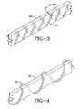
- the pitch on the antenna zigzag, ⁇ , shown in FIG. 3 may be preselected based upon the angle necessary to accommodate predicted elongation.
- FIG. 4 shows the antenna 32 in an alternate embodiment in which the antenna is a helical wrap surrounding an elastic Spandex core 36.
- the helical wrap allows for an elongation of antenna 32 in conjunction with core 36 in the manner described above.
- the wrap on the elastic tube with preferred dimensions between 1-1.5 mm in diameter, can be a single cable/filament, multiple individual parallel filament wraps, a braided structure, or filaments cabled upon the core to lie in the same direction.
- the width of the strip may be selected to provide the requisite elastic performance.
- 1 ⁇ 4 inch to 1 ⁇ 2 inch wide spandex material having a thickness of 1 mm may be used.
- Antenna 32 may be sewn to the substrate 36 by the use of a conventional needle to form the desired finished antenna apparatus.
- an adhesive of the type commercially available may be applied to the substrate 36 to retain the antenna wire(s) in place.
- the subject invention satisfies the need of the industry for a convenient, reliable method of affixing an antenna in annular form to the inside of a tire.
- Use of an elasticized textile as a substrate for holding the antenna in an optimal configuration when in a relaxed state is economical and highly effective.
- the substrate extends from an initial relaxed state when the stresses within a tire are imposed; the material of the substrate and the curvilinear configuration of the antenna accommodating such an elongation.
- the recovery of the substrate to its original form is predictable, and durable enough to withstand the necessary number of elongation/recovery cycles within a typical tire used in an intended manner.
- LYCRA SPANDEX registered trademark of E.I.
- DuPont de Nemours & Company is one material that may be employed.
- Other commercially available stretch fabrics may also be utilized. Such fabrics are available having a selection of stretch resistance, stress decay, hysteresis, residual stretch, and recovery characteristics. Materials will generally have a cycle limit, representing the greatest elongation to which the material may be subjected without resulting in a permanent deformation.
- the holding power and stretch resistance may further be selected to provide an optimum match between the elasticized characteristics of the substrate 36 and the magnitude of elongation required due to stresses from use within a tire environment.
- the advantages of the subject invention over antenna apparatus composed of a rubber carrier strip are significant.
- Spandex fiber construction can be stretched repeatedly and still recover to very near original length and strength; the material may be stretched through a high number of cycles without breaking; the material is stronger, more durable and exhibits a higher retractive force than rubber.
- elasticized fabric is lightweight, supple and may be formed into a wide variety of shapes.
Landscapes
- Engineering & Computer Science (AREA)
- Mechanical Engineering (AREA)
- Tires In General (AREA)
- Support Of Aerials (AREA)
- Measuring Fluid Pressure (AREA)
- Arrangements For Transmission Of Measured Signals (AREA)
Claims (8)
- Bandage pneumatique dans lequel est incorporé un assemblage d'antenne, le bandage pneumatique (12) comprenant :une carcasse de bandage pneumatique possédant une paroi orientée vers l'intérieur ;une antenne allongée (32) ; etune bande de support allongée constituée d'une matière élastique non conductrice fixée à l'antenne (32) pour maintenir l'antenne (32) dans une configuration donnée, la bande de support (36) venant se fixer à la paroi interne du bandage pneumatique (12) et s'étendant, depuis un état relâché initial jusqu'à un état étendu lorsqu'elle est soumise à des contraintes au sein du bandage pneumatique, et en récupérant essentiellement à partir de l'état étendu en l'absence desdites contraintes, caractérisé en ce que la bande de support (36) est composée essentiellement d'une matière fibreuse élastique, ou bien dans lequel la bande de support (36) comprend au moins une bande de tissu textile tissée à partir d'une matière fibreuse élastique.
- Bandage pneumatique selon la revendication 1, dans lequel l'antenne (32) est cousue au moins en partie à une bande de tissu textile, l'antenne (32) étant tissée au moins en partie à travers la bande de tissu textile, ou bien dans lequel l'antenne (32) est enroulée au moins en partie autour de la bande de tissu textile.
- Bandage pneumatique selon la revendication 1 ou 2, dans lequel le bandage pneumatique est monté sur une jante de roue (26) et la région de flanc inférieur du bandage pneumatique (12) est située à une certaine distance au-dessus d'une surface limite supérieure de la jante de roue (26).
- Bandage pneumatique selon au moins une des revendications précédentes, dans lequel l'antenne présente une configuration en zigzag s'étendant en formant un pas présélectionné à travers le tissu textile.
- Procédé pour le montage d'une antenne annulaire (32) et d'un transpondeur (34) sur un bandage pneumatique (12), comprenant les étapes consistant à :procurer une antenne allongée (32) ;fixer l'antenne (32) à une bande de support allongée (36) constituée d'une matière élastique qui s'étend depuis un état relâché initial jusqu'à un état étendu lorsqu'elle est soumise à des contraintes au sein du bandage pneumatique (12) et qui récupère essentiellement à partir de l'état étendu en l'absence desdites contraintes, afin de maintenir l'antenne (32) dans une configuration donnée ; etfixer la bande de support (36) à une paroi interne d'un bandage pneumatique (12),caractérisé en ce que le procédé comprend l'étape consistant à former la bande de support à partir d'au moins une bande de tissu textile (36) tissée à partir d'une matière fibreuse élastique.
- Procédé selon la revendication 5, comprenant l'étape supplémentaire consistant à coudre au moins en partie l'antenne (32) à ladite une bande de tissu textile (36).
- Procédé selon la revendication 6, comprenant l'étape supplémentaire consistant à conférer à l'antenne (32) une configuration en zigzag s'étendant en formant un pas présélectionné à travers le tissu textile.
- Procédé selon au moins une des revendications 5 à 7, comprenant l'étape supplémentaire consistant à tisser au moins en partie au moins une portion de l'antenne (32) dans ladite une bande de tissu textile.
Applications Claiming Priority (2)
| Application Number | Priority Date | Filing Date | Title |
|---|---|---|---|
| US745306 | 2003-12-22 | ||
| US10/745,306 US7104298B2 (en) | 2003-12-22 | 2003-12-22 | Tire having antenna attached to elastic fiber textile strip and method of mounting antenna assembly to tire |
Publications (3)
| Publication Number | Publication Date |
|---|---|
| EP1547824A2 EP1547824A2 (fr) | 2005-06-29 |
| EP1547824A3 EP1547824A3 (fr) | 2006-02-15 |
| EP1547824B1 true EP1547824B1 (fr) | 2009-03-11 |
Family
ID=34552869
Family Applications (1)
| Application Number | Title | Priority Date | Filing Date |
|---|---|---|---|
| EP04106688A Expired - Lifetime EP1547824B1 (fr) | 2003-12-22 | 2004-12-17 | Assemblage d'antenne à haut allongement et procédé pour un pneumatique |
Country Status (6)
| Country | Link |
|---|---|
| US (1) | US7104298B2 (fr) |
| EP (1) | EP1547824B1 (fr) |
| JP (1) | JP2005178747A (fr) |
| BR (1) | BRPI0405519A (fr) |
| CA (1) | CA2486306A1 (fr) |
| DE (1) | DE602004019873D1 (fr) |
Families Citing this family (31)
| Publication number | Priority date | Publication date | Assignee | Title |
|---|---|---|---|---|
| JP4066929B2 (ja) * | 2003-10-08 | 2008-03-26 | 株式会社日立製作所 | 電子装置及びその製造方法 |
| US20050133132A1 (en) * | 2003-12-23 | 2005-06-23 | Jean-Claude Girard | Apparatus and method for incorporating an annular antenna and electronics into a tire |
| JP3930024B2 (ja) * | 2004-02-17 | 2007-06-13 | 京セラ株式会社 | タイヤ空気圧情報送信装置及びこれを用いたタイヤ空気圧情報送信装置付きホイール |
| US7492328B2 (en) | 2004-07-30 | 2009-02-17 | The Goodyear Tire & Rubber Company | Composite antenna for a tire |
| US7250914B2 (en) * | 2004-07-30 | 2007-07-31 | The Goodyear Tire & Rubber Company | Composite antenna for a tire |
| CA2517822C (fr) * | 2004-09-06 | 2009-10-27 | Honda Motor Co., Ltd. | Structure de support de siege pour vehicule a selle |
| JP4675966B2 (ja) * | 2004-11-05 | 2011-04-27 | ピレリ・タイヤ・ソチエタ・ペル・アツィオーニ | アンテナを備えた車輪用空気圧タイヤ及びそれを製造する方法 |
| EP1855897B1 (fr) * | 2005-03-09 | 2010-08-11 | Société de Technologie Michelin | Support robuste pour antenne de transpondeur rfid |
| FR2883222B1 (fr) * | 2005-03-21 | 2007-05-18 | Michelin Soc Tech | Procede d'obtention d'un fil preforme destine a etre integre lors de la fabrication d'un pneummatique, ensemble d'une feuille de gomme et d'un fil preforme |
| US7705733B2 (en) * | 2006-01-06 | 2010-04-27 | Warsaw Orthopedic, Inc. | Coiled RFID tag |
| WO2007083337A1 (fr) * | 2006-01-23 | 2007-07-26 | Sonia Deola | Circuit integre d'identification a haute frequence (rfid) comportant une antenne extensible et utilisations appropriees |
| DE102006054449A1 (de) * | 2006-11-16 | 2008-05-21 | Smartrac Ip B.V. | Transpondereinheit |
| US7903038B2 (en) * | 2006-12-08 | 2011-03-08 | Lockheed Martin Corporation | Mobile radar array |
| US7453407B2 (en) * | 2006-12-30 | 2008-11-18 | The Goodyear Tire & Rubber Company | Antenna constructions for electronic devices and methods for manufacturing such antenna constructions |
| US8776851B2 (en) | 2008-08-29 | 2014-07-15 | The Goodyear Tire & Rubber Company | Film to keep tire surface clean and simultaneously prime for better adhesion of balance pad |
| CN102189904A (zh) * | 2010-03-10 | 2011-09-21 | 台达电子工业股份有限公司 | 胎压监控的智能型天线系统及方法及智能型胎压监测系统 |
| US20110254677A1 (en) * | 2010-04-19 | 2011-10-20 | Sun chun-yi | Smart antenna system and method for tire pressure monitoring and smart tire pressure monitoring system |
| US9656434B2 (en) | 2010-11-30 | 2017-05-23 | The Good Year Tire & Rubber Company | Measuring tire pressure in a tire mold |
| CN106575369B (zh) | 2014-07-31 | 2019-09-13 | 3M创新有限公司 | 柔性基底上的rfid标签 |
| US10229353B2 (en) | 2014-07-31 | 2019-03-12 | 3M Innovative Properties Company | RFID tag on stretchable substrate |
| KR101666965B1 (ko) * | 2015-04-29 | 2016-10-17 | 씨트론 주식회사 | Tpms용 센서 부착장치 |
| DE102016214089A1 (de) * | 2016-07-29 | 2018-02-01 | Alligator Ventilfabrik Gmbh | Befestigungsvorrichtung zum Befestigen eines Messsensors, insbesondere Reifendrucksensors |
| EP3774400B1 (fr) * | 2018-03-30 | 2022-05-18 | Compagnie Generale Des Etablissements Michelin | Transpondeur radiofrequence pour pneumatique |
| JP7173141B2 (ja) * | 2018-06-22 | 2022-11-16 | 横浜ゴム株式会社 | 空気入りタイヤおよびアセンブリシート |
| JP6582105B1 (ja) * | 2018-10-03 | 2019-09-25 | Toyo Tire株式会社 | タイヤの製造方法 |
| DE102019205298A1 (de) * | 2019-04-12 | 2020-10-15 | Continental Reifen Deutschland Gmbh | Reifen |
| FR3114994B1 (fr) * | 2020-10-09 | 2023-01-13 | Beringer Aero | Dispositif de contrôle de la pression d’un pneumatique d’une roue d’avion |
| EP4240580B1 (fr) * | 2020-11-03 | 2024-10-30 | TYG S.r.l. | Procédé d'incorporation d'un dispositif de poursuite dans un corps de matériau élastomère et corps traçable obtenu ainsi |
| DE102021206658A1 (de) * | 2021-06-28 | 2022-12-29 | Contitech Techno-Chemie Gmbh | Identifikationselement für Medienführungen |
| WO2023166426A1 (fr) * | 2022-03-02 | 2023-09-07 | Avery Dennison Retail Information Services Llc | Étiquettes rfid à fil souple |
| KR102835030B1 (ko) * | 2024-06-11 | 2025-07-16 | 주식회사 윌켐코리아 | 타이어 매설용 무선인식태그 및 그 제조방법 |
Family Cites Families (18)
| Publication number | Priority date | Publication date | Assignee | Title |
|---|---|---|---|---|
| US3662335A (en) * | 1969-10-08 | 1972-05-09 | Kurt Fritze | Device for road vehicles for the wireless transmission of at least one measured value of a rotating wheel to an indicating instrument |
| US4319220A (en) * | 1976-08-31 | 1982-03-09 | Dennis G. Pappas | Alarm system for monitoring pressurized vehicular tires |
| US4769656A (en) * | 1987-01-28 | 1988-09-06 | Timex Corporation | Expansion band antenna for a wrist instrument and method of making it |
| US4754285A (en) * | 1987-05-01 | 1988-06-28 | Timex Corporation | Expansion band antenna for a wristwatch application |
| US5479171A (en) * | 1993-04-27 | 1995-12-26 | Texas Instruments Deutschland Gmbh | Extended range RF-ID transponder |
| US5541574A (en) * | 1993-12-22 | 1996-07-30 | Palomar Technologies Corporation | Transponder system for communicating with a vehicle tire |
| US5872186A (en) * | 1996-02-16 | 1999-02-16 | E. I. Du Pont De Nemours And Company | Spandex blended in natural rubber |
| DE69719822T2 (de) | 1997-12-09 | 2003-11-20 | The Goodyear Tire & Rubber Co., Akron | Ringförmige vorrichtung zur reifendatenübertragung, vorrichtung zur messung von reifenparametern mit einem transponder, eine antenne und ein luftreifen mit einem transponder und einer antenne |
| CA2312153A1 (fr) | 1997-12-09 | 1999-06-17 | The Goodyear Tire & Rubber Company | Antenne pour repondeur radio |
| DE69725476T2 (de) * | 1997-12-09 | 2004-07-22 | The Goodyear Tire & Rubber Co., Akron | Luftreifen mit einem transponder und einer ringförmigen antenne und verfahren zur herstellung eines derartigen reifens |
| JP4298922B2 (ja) * | 1998-08-03 | 2009-07-22 | ザ・グッドイヤー・タイヤ・アンド・ラバー・カンパニー | 空気入りタイヤ内へのトランスポンダの取り付け |
| US7190319B2 (en) * | 2001-10-29 | 2007-03-13 | Forster Ian J | Wave antenna wireless communication device and method |
| FR2817509B1 (fr) * | 2000-12-05 | 2003-08-29 | Trw France | Systeme de mesure de parametres de roue et detecteur de mesure pour un tel systeme |
| DE10154494A1 (de) * | 2001-11-08 | 2003-05-22 | Continental Ag | Sende- und/oder Empfangseinrichtung zum Einbau in elastische Strukturen sowie Antennen hierfür |
| US6809700B2 (en) * | 2002-07-24 | 2004-10-26 | The Goodyear Tire & Rubber Company | Tag housing and assembly method for annular apparatus |
| EP1454770A1 (fr) * | 2003-03-04 | 2004-09-08 | Société de Technologie Michelin | Dispositif électronique pour un pneumatique avec une antenne elastique et un pneumatique comportant ce dispositif |
| US6966219B2 (en) * | 2003-12-22 | 2005-11-22 | The Goodyear Tire & Rubber Company | Tire antenna containment system and method |
| US6978668B2 (en) * | 2003-12-22 | 2005-12-27 | The Goodyear Tire & Rubber Company | Flexible tinsel ribbon antenna and assembly method for a tire |
-
2003
- 2003-12-22 US US10/745,306 patent/US7104298B2/en not_active Expired - Fee Related
-
2004
- 2004-10-29 CA CA002486306A patent/CA2486306A1/fr not_active Abandoned
- 2004-12-10 JP JP2004357676A patent/JP2005178747A/ja not_active Ceased
- 2004-12-14 BR BR0405519-5A patent/BRPI0405519A/pt not_active IP Right Cessation
- 2004-12-17 DE DE602004019873T patent/DE602004019873D1/de not_active Expired - Fee Related
- 2004-12-17 EP EP04106688A patent/EP1547824B1/fr not_active Expired - Lifetime
Also Published As
| Publication number | Publication date |
|---|---|
| US20050133131A1 (en) | 2005-06-23 |
| EP1547824A2 (fr) | 2005-06-29 |
| JP2005178747A (ja) | 2005-07-07 |
| US7104298B2 (en) | 2006-09-12 |
| BRPI0405519A (pt) | 2005-08-30 |
| CA2486306A1 (fr) | 2005-06-22 |
| EP1547824A3 (fr) | 2006-02-15 |
| DE602004019873D1 (de) | 2009-04-23 |
Similar Documents
| Publication | Publication Date | Title |
|---|---|---|
| EP1547824B1 (fr) | Assemblage d'antenne à haut allongement et procédé pour un pneumatique | |
| EP1547825B1 (fr) | Antenne flexible à ruban métallique et procédé d'assemblage pour un pneu | |
| US7102499B2 (en) | Electronic device for a tire having an extensible antenna | |
| US7492328B2 (en) | Composite antenna for a tire | |
| EP1049196B1 (fr) | Antenne dipôle dans des pneus pour automobiles | |
| US7592902B2 (en) | Monitoring device and tire combination | |
| US20030085619A1 (en) | Transmitting and/or receiving unit for incorporation into an elastic structure | |
| AU2002234259A1 (en) | Monitoring device and tire combination | |
| US7017405B2 (en) | System and method for post-cure application of electronics to a tire | |
| CN114829159A (zh) | 具有射频转发器的轮胎 | |
| US7250914B2 (en) | Composite antenna for a tire | |
| US6966219B2 (en) | Tire antenna containment system and method | |
| US20060070230A1 (en) | Annular wire antenna and transponder apparatus method of assembly | |
| EP1454771B1 (fr) | Dispositif électronique pour un pneumatique avec une antenne elastique et un pneumatique comportant ce dispositif |
Legal Events
| Date | Code | Title | Description |
|---|---|---|---|
| PUAI | Public reference made under article 153(3) epc to a published international application that has entered the european phase |
Free format text: ORIGINAL CODE: 0009012 |
|
| AK | Designated contracting states |
Kind code of ref document: A2 Designated state(s): AT BE BG CH CY CZ DE DK EE ES FI FR GB GR HU IE IS IT LI LT LU MC NL PL PT RO SE SI SK TR |
|
| AX | Request for extension of the european patent |
Extension state: AL BA HR LV MK YU |
|
| PUAL | Search report despatched |
Free format text: ORIGINAL CODE: 0009013 |
|
| AK | Designated contracting states |
Kind code of ref document: A3 Designated state(s): AT BE BG CH CY CZ DE DK EE ES FI FR GB GR HU IE IS IT LI LT LU MC NL PL PT RO SE SI SK TR |
|
| AX | Request for extension of the european patent |
Extension state: AL BA HR LV MK YU |
|
| 17P | Request for examination filed |
Effective date: 20060816 |
|
| AKX | Designation fees paid |
Designated state(s): DE FR GB IT |
|
| 17Q | First examination report despatched |
Effective date: 20061130 |
|
| GRAP | Despatch of communication of intention to grant a patent |
Free format text: ORIGINAL CODE: EPIDOSNIGR1 |
|
| GRAS | Grant fee paid |
Free format text: ORIGINAL CODE: EPIDOSNIGR3 |
|
| GRAA | (expected) grant |
Free format text: ORIGINAL CODE: 0009210 |
|
| AK | Designated contracting states |
Kind code of ref document: B1 Designated state(s): DE FR GB IT |
|
| REG | Reference to a national code |
Ref country code: GB Ref legal event code: FG4D |
|
| REF | Corresponds to: |
Ref document number: 602004019873 Country of ref document: DE Date of ref document: 20090423 Kind code of ref document: P |
|
| PLBE | No opposition filed within time limit |
Free format text: ORIGINAL CODE: 0009261 |
|
| STAA | Information on the status of an ep patent application or granted ep patent |
Free format text: STATUS: NO OPPOSITION FILED WITHIN TIME LIMIT |
|
| 26N | No opposition filed |
Effective date: 20091214 |
|
| GBPC | Gb: european patent ceased through non-payment of renewal fee |
Effective date: 20091217 |
|
| REG | Reference to a national code |
Ref country code: FR Ref legal event code: ST Effective date: 20100831 |
|
| PG25 | Lapsed in a contracting state [announced via postgrant information from national office to epo] |
Ref country code: FR Free format text: LAPSE BECAUSE OF NON-PAYMENT OF DUE FEES Effective date: 20091231 |
|
| PG25 | Lapsed in a contracting state [announced via postgrant information from national office to epo] |
Ref country code: DE Free format text: LAPSE BECAUSE OF NON-PAYMENT OF DUE FEES Effective date: 20100701 |
|
| PG25 | Lapsed in a contracting state [announced via postgrant information from national office to epo] |
Ref country code: GB Free format text: LAPSE BECAUSE OF NON-PAYMENT OF DUE FEES Effective date: 20091217 |
|
| PG25 | Lapsed in a contracting state [announced via postgrant information from national office to epo] |
Ref country code: IT Free format text: LAPSE BECAUSE OF FAILURE TO SUBMIT A TRANSLATION OF THE DESCRIPTION OR TO PAY THE FEE WITHIN THE PRESCRIBED TIME-LIMIT Effective date: 20090311 |