EP1547514A1 - Endoscope apparatus - Google Patents
Endoscope apparatus Download PDFInfo
- Publication number
- EP1547514A1 EP1547514A1 EP04030522A EP04030522A EP1547514A1 EP 1547514 A1 EP1547514 A1 EP 1547514A1 EP 04030522 A EP04030522 A EP 04030522A EP 04030522 A EP04030522 A EP 04030522A EP 1547514 A1 EP1547514 A1 EP 1547514A1
- Authority
- EP
- European Patent Office
- Prior art keywords
- assisting tool
- balloon
- insertion assisting
- insertion section
- tip end
- Prior art date
- Legal status (The legal status is an assumption and is not a legal conclusion. Google has not performed a legal analysis and makes no representation as to the accuracy of the status listed.)
- Granted
Links
- 238000003780 insertion Methods 0.000 claims abstract description 223
- 230000037431 insertion Effects 0.000 claims abstract description 223
- 230000003287 optical effect Effects 0.000 claims description 31
- 238000001514 detection method Methods 0.000 claims description 5
- 230000000968 intestinal effect Effects 0.000 abstract description 18
- XLYOFNOQVPJJNP-UHFFFAOYSA-N water Substances O XLYOFNOQVPJJNP-UHFFFAOYSA-N 0.000 description 12
- 238000010276 construction Methods 0.000 description 11
- 230000002093 peripheral effect Effects 0.000 description 11
- 238000000034 method Methods 0.000 description 8
- 230000002265 prevention Effects 0.000 description 8
- 238000013459 approach Methods 0.000 description 5
- 238000005286 illumination Methods 0.000 description 5
- 238000005452 bending Methods 0.000 description 4
- 239000012530 fluid Substances 0.000 description 4
- 238000010586 diagram Methods 0.000 description 2
- 229920001971 elastomer Polymers 0.000 description 2
- 210000000813 small intestine Anatomy 0.000 description 2
- 210000001198 duodenum Anatomy 0.000 description 1
- 230000000694 effects Effects 0.000 description 1
- -1 for example Substances 0.000 description 1
- 239000011261 inert gas Substances 0.000 description 1
- 210000002429 large intestine Anatomy 0.000 description 1
- 239000004816 latex Substances 0.000 description 1
- 229920000126 latex Polymers 0.000 description 1
- 239000000314 lubricant Substances 0.000 description 1
- 238000004804 winding Methods 0.000 description 1
Images






Classifications
-
- A—HUMAN NECESSITIES
- A61—MEDICAL OR VETERINARY SCIENCE; HYGIENE
- A61B—DIAGNOSIS; SURGERY; IDENTIFICATION
- A61B1/00—Instruments for performing medical examinations of the interior of cavities or tubes of the body by visual or photographical inspection, e.g. endoscopes; Illuminating arrangements therefor
- A61B1/00147—Holding or positioning arrangements
- A61B1/00154—Holding or positioning arrangements using guiding arrangements for insertion
-
- A—HUMAN NECESSITIES
- A61—MEDICAL OR VETERINARY SCIENCE; HYGIENE
- A61B—DIAGNOSIS; SURGERY; IDENTIFICATION
- A61B1/00—Instruments for performing medical examinations of the interior of cavities or tubes of the body by visual or photographical inspection, e.g. endoscopes; Illuminating arrangements therefor
- A61B1/00064—Constructional details of the endoscope body
- A61B1/00071—Insertion part of the endoscope body
- A61B1/0008—Insertion part of the endoscope body characterised by distal tip features
- A61B1/00082—Balloons
-
- A—HUMAN NECESSITIES
- A61—MEDICAL OR VETERINARY SCIENCE; HYGIENE
- A61B—DIAGNOSIS; SURGERY; IDENTIFICATION
- A61B1/00—Instruments for performing medical examinations of the interior of cavities or tubes of the body by visual or photographical inspection, e.g. endoscopes; Illuminating arrangements therefor
- A61B1/005—Flexible endoscopes
- A61B1/01—Guiding arrangements therefore
-
- A—HUMAN NECESSITIES
- A61—MEDICAL OR VETERINARY SCIENCE; HYGIENE
- A61B—DIAGNOSIS; SURGERY; IDENTIFICATION
- A61B1/00—Instruments for performing medical examinations of the interior of cavities or tubes of the body by visual or photographical inspection, e.g. endoscopes; Illuminating arrangements therefor
- A61B1/012—Instruments for performing medical examinations of the interior of cavities or tubes of the body by visual or photographical inspection, e.g. endoscopes; Illuminating arrangements therefor characterised by internal passages or accessories therefor
- A61B1/018—Instruments for performing medical examinations of the interior of cavities or tubes of the body by visual or photographical inspection, e.g. endoscopes; Illuminating arrangements therefor characterised by internal passages or accessories therefor for receiving instruments
-
- A—HUMAN NECESSITIES
- A61—MEDICAL OR VETERINARY SCIENCE; HYGIENE
- A61B—DIAGNOSIS; SURGERY; IDENTIFICATION
- A61B1/00—Instruments for performing medical examinations of the interior of cavities or tubes of the body by visual or photographical inspection, e.g. endoscopes; Illuminating arrangements therefor
- A61B1/12—Instruments for performing medical examinations of the interior of cavities or tubes of the body by visual or photographical inspection, e.g. endoscopes; Illuminating arrangements therefor with cooling or rinsing arrangements
Definitions
- the present invention relates to an endoscope apparatus, and particularly relates to an endoscope apparatus which has a balloon fitted onto an insertion section of an endoscope, and which performs observation by inserting the insertion section into a deep alimentary canal such as a small intestine and a large intestine by alternately inserting an insertion assisting tool covering the insertion section, and the insertion section.
- an endoscope apparatus provided with a first balloon at a tip end part of an insertion section of the endoscope and provided with a second balloon at a tip end part of the insertion assisting tool (also called an over tube or a sliding tube) is described.
- an insertion section 1 of an endoscope is first inserted into a intestinal canal 3 with an insertion assisting tool 2 covering the insertion section 1 and a tip end part 1a of the insertion section 1 is inserted into as deep a part as possible, as shown in Fig. 10A.
- a first balloon 4 fitted onto the tip end part 1a is inflated and fixed to the intestinal canal 3 as shown in Fig. 10B.
- the insertion section 1 is drawn in hand over hand to remove excessive deflection of the insertion section 1, and makes the insertion section 1 as linear a shape as possible.
- the insertion assisting tool 2 is pushed through along the insertion section 1, and a tip end part 2a of the insertion assisting tool 2 is disposed near a tip end part 1a of the insertion section 1.
- a second balloon 5 is inflated, and the tip end part 2a of the insertion assisting tool 2 is fixed to the intestinal canal 3.
- the insertion section 1 is inserted as deep as possible again.
- the insertion section 1 is guided by the insertion assisting tool 2, and therefore, the insertion section 1 can be smoothly inserted.
- the tip end part 1a of the insertion section 1 can be inserted into a deep part even in the intestinal canal 3 that is complicatedly bent.
- Japanese Patent Application Laid-open No. 51-11689 has the fear that when the insertion section 1 is drawn in, a tip end of the insertion assisting tool 2 contacts the first balloon 4 and damages the first balloon 4.
- the present invention is made in view of the above circumstances, and has its object to provide an endoscope apparatus which can prevent a balloon fitted onto an insertion section from contacting an insertion assisting tool and being damaged.
- a first aspect of the present invention is in an endoscope apparatus having an endoscope with an insertion section connected to a hand operation section and a balloon fitted onto the insertion section, and an insertion assisting tool which covers the insertion section and guides insertion of the insertion section into a body cavity, characterized by comprising a contact preventing device which prevents a tip end of the insertion assisting tool from contacting the balloon.
- the contact preventing device is provided, and therefore, the tip end of the insertion assisting tool can be prevented from contacting the balloon, thus making it possible to prevent damage to the balloon.
- a second aspect of the present invention is, in the first aspect, characterized in that the contact preventing device is an indicator formed at an outer surface of the insertion section, and the indicator appears from a base end side of the insertion assisting tool when the insertion assisting tool is relatively moved to a tip end side of the insertion section, and the tip end of the insertion assisting tool comes close to the balloon.
- the indicator when the insertion assisting tool is moved to the tip end side of the insertion section, the indicator appears before the tip end of the insertion assisting tool contacts the balloon, and therefore, the insertion assisting tool can be prevented from contacting the balloon.
- a third aspect of the present invention is, in the first aspect, characterized in that the contact preventing device is a string-shaped member which connects the insertion assisting tool and the hand operation section.
- the tip end of the insertion assisting tool can be prevented from contacting the balloon by the string-shaped member connecting the insertion assisting tool and the hand operation section.
- a fourth aspect of the present invention is, in the first aspect, characterized in that the contact preventing device comprises an optical sensor provided at one of the insertion section and the insertion assisting tool, an indicator for optical detection provided at the other one of the insertion section and the insertion assisting tool, and detected by the optical sensor when the tip end of the insertion assisting tool comes close to the balloon, and a warning device which performs warning when the optical sensor detects the indicator.
- the optical sensor detects the indicator for optical detection and warning is issued, whereby the insertion assisting tool can be prevented from contacting the balloon.
- a fifth aspect of the present invention is, in the first aspect, characterized in that the contact preventing device comprises a magnetic sensor provided at one of the insertion section and the insertion assisting tool, a magnetic body provided at the other one of the insertion section and the insertion assisting tool, and detected by the magnetic sensor when the tip end of the insertion assisting tool comes close to the balloon, and a warning device which performs warning when the magnetic sensor detects the magnetic body.
- the magnetic sensor detects the magnetic body and the warning is issued, whereby the insertion assisting tool can be prevented from contacting the balloon.
- the tip end of the insertion assisting tool can be prevented from contacting the balloon by the contact preventing device, and damage to the balloon can be prevented.
- Fig. 1 shows a system schematic diagram showing an embodiment of an endoscope apparatus according to the present invention.
- the endoscope apparatus shown in Fig. 1 is mainly constructed by an endoscope 10, a light source device 20, a processor 30, a balloon control device 66 and an insertion assisting tool 70.
- the endoscope 10 comprises an insertion section 12 which is inserted into a body cavity and a hand operation section 14 connected to the insertion section 12, and a universal cable 16 is connected to the hand operation section 14.
- An LG connector 18 is provided at a tip end of the universal cable 16, and the LG connector 18 is connected to the light source device 20.
- An electric connector 24 is connected to the LG connector 18 via a cable 22, and the electric connector 24 is connected to the processor 30.
- An air/water supply tube 26 for supplying air and water, and a suction tube 28 for sucking air are connected to the LG connector 18.
- an air/water passing button 32, a suction button 34 and a shutter button 36 are provided in parallel, and a pair of angle knobs 38 and 38, and a forceps insertion part 40 are provided.
- a supply/suction port 44 for supplying fluid to a first balloon 42 which will be described later and sucking fluid from the first balloon 42 is provided at a base end part of the hand operation section 14.
- air as the fluid
- the other fluid for example, inert gas and water may be used.
- the insertion section 12 is constructed by a tip end part 46, a curving part 48 and a flexible part 50, the curving part 48 is remotely operated to curve by rotating a pair of angle knobs 38 and 38 provided on the hand operation section 14. Thereby, a tip end surface 47 of the tip end part 46 can be directed to a desired direction.
- the tip end surface 47 of the tip end part 46 is provided with an observation optical system 52, an illumination optical system 54, an air/water passing nozzle 56, a forceps port 58 and the like.
- CCD (not shown) is placed behind the observation optical system 52, and a signal cable is connected to the base board supporting the CCD.
- the signal cable is provided to extend to the electric connector 24 by being inserted through the insertion section 12, the hand operation section 14 and the universal cable 16 in Fig. 1, and is connected to the processor 30.
- an observed image taken by the observation optical system 52 is formed on a light-receiving surface of the CCD, and converted into an electrical signal, and the electrical signal is outputted to the processor 30 via the signal cable, and converted into a picture signal. Thereby, the observed image is displayed on a monitor 60 connected to the processor 30.
- An emission end of a light guide (not shown) is placed behind the illumination optical systems 54 in Fig. 2.
- the light guide is inserted through the insertion section 12, the hand operation section 14 and the universal cable 16 in Fig. 1, and an incident end is placed at the LG connector 18.
- the illumination light which is irradiated from the light source device 20 is transmitted to the illumination optical systems 54 via the light guide, and is irradiated from the illumination optical systems 54.
- the air/water passing nozzle 56 (see Fig. 2) is inserted through a valve (not shown) which is operated by the air/water passing button 32, and is further inserted through the air/water supplying tube 26. Accordingly, by operating the air/water passing button 32, air or water is injected toward the observation optical system 52 from the air/water passing nozzle 56.
- the forceps port 58 (see Fig. 2) is inserted through the forceps insertion part 40, and is inserted through a valve (not shown) which is operated by the suction button 34, and further inserted through the suction tube 28. Accordingly, by operating the suction button 34, a diseased portion and the like are sucked from the forceps port 58, and by inserting an operative instrument from the forceps insertion part 40, the operative instrument is led out of the forceps port 58.
- the first balloon 42 made of an elastic body such as rubber is fitted onto an outer peripheral surface of the insertion section 12.
- the first balloon 42 is formed in a substantially cylindrical shape with both end portions narrowed down, and is fitted by fixing both the end portions of the first balloon 42 to the insertion section 12 after the insertion section 12 is inserted through the first balloon 42.
- a thread is wound around both the end portions of the first balloon 42, for example, and the first balloon 42 is closely fitted onto the entire periphery of the outer peripheral surface of the insertion section 12.
- fixing rings may be fitted onto both the end portions of the first balloon 42.
- An air port 62 is formed at the attaching position of the first balloon 42 to the insertion section 12.
- the air port 62 communicates with the supply/suction port 44 of the hand operation section 14 in Fig. 1.
- a tube 64 is connected to the supply/suction port 44 and the tube 64 is connected to the balloon control device 66.
- the balloon control device 66 is a device which supplies air to the first balloon 42 and sucks air via the tube 64, and controls the air pressure on the supply and suction of air, and is operated by an operation button 68 provided at a front surface.
- the first balloon 42 is inflated in a substantially spherical shape by supplying air, and attached onto the outer surface of the insertion section 12 by sucking air.
- the insertion assisting tool 70 is formed in a cylindrical shape, and has a slightly larger inner diameter than the outer diameter of the insertion section 12, and includes sufficient flexibility.
- a rigid gripping portion 74 is provided at a base end of the insertion assisting tool 70, and the insertion section 12 is inserted from the gripping part 74.
- a balloon air port 78 is provided at a base end side of the insertion assisting tool 70.
- An air supply tube 76 with an inner diameter of about 1 mm is connected to the balloon air port 78, and the air supply tube 76 is bonded to an outer peripheral surface of the insertion assisting tool 70, and provided to extend to the tip end part of the insertion assisting tool 70.
- a second balloon 72 made of latex is fitted to the vicinity of the tip end of the insertion assisting tool 70.
- the second balloon 72 is formed into a substantially cylindrical shape with both ends narrowed, and is fitted onto the insertion assisting tool 70 with the insertion assisting tool 70 penetrated through the second balloon 72.
- the aforementioned tube 76 is opened inside the second balloon 72, and the second balloon 72 communicates with the balloon air port 78 via the tube 76.
- a tip end of a tube 80 is connected to the balloon air port 78, and a base end of the tube 80 is connected to the aforementioned balloon control device 66. Accordingly, when air is supplied to the balloon air port 78 by the balloon control device 66, air is blown into the second balloon 72, whereby the second balloon 72 is inflated.
- Reference numeral 84 in Fig. 1 designates an inlet port for filling a lubricant such as water into the insertion assisting tool 70.
- the insertion section 12 is inserted into an intestinal canal (for example, descending limb of duodenum) in the state in which the insertion assisting tool 70 covers the insertion section 12.
- the first balloon 42 and the second balloon 72 are deflated.
- the insertion assisting tool 70 is pushed in, and inserted along the insertion section 12, as shown in Fig. 3E (pushing operation). Then, after the tip end of the insertion assisting tool 70 is pushed into the vicinity of the first balloon 42, air is supplied to the second balloon 72 to inflate the second balloon 72 as shown in Fig. 3F. As a result, the second balloon 72 is fixed to the intestinal canal 90. Namely, the intestinal canal 90 is gripped by the second balloon 72 (gripping operation).
- the insertion assisting tool 70 is drawn in (drawing operation). Thereby, the intestinal canal 90 is in the contracted state, and excessive deflection and bending of the insertion assisting tool 70 are eliminated.
- the tip end part 46 of the insertion section 12 is inserted into as deep a part of the intestinal canal 90 as possible. Namely, the inserting operation as shown in Fig. 3C is performed again. Thereby, the tip end part 46 of the insertion section 12 can be inserted into a deep part of the intestinal canal 90.
- the pushing operation as shown in Fig. 3E is performed after the fixing operation as shown in Fig. 3D is performed, the gripping operation as shown in Fig. 3F and the drawing operation as shown in Fig. 3G, and the inserting operation as shown in Fig. 3H are repeatedly performed in sequence.
- the insertion section 12 can be further inserted into a deep part of the intestinal canal 90.
- the endoscope apparatus is provided with a contact preventing device which prevents the insertion assisting tool 70 from contacting the first balloon 42 when the pushing operation shown in Fig. 3E is performed.
- Fig. 4 is a schematic view showing a construction of a first embodiment of the contact preventing device.
- a contact prevention indicator 100 for contact prevention is formed on the outer peripheral surface of the insertion 12 shown in Fig. 4.
- the contact prevention indicator 100 is formed at the position where it appears from the base end side of the insertion assisting tool 70 when the tip end of the insertion assisting tool 70 is in the state in which the tip end of the insertion assisting tool 70 approaches the first balloon 42, but does not contact the first balloon 42 (hereinafter, called a limit state) as shown in Fig. 4.
- scales 102 and the like are formed on the insertion section 12, it is preferable to form the contact prevention indicator 100 to be different in thickness, color, shape and the like from the scale 102 to be recognized as the contact prevention indicator 100 at a glance. For example, it is preferable to form the contact prevention indicator 100 to be thicker than the scale 102 or form it in a different color from the scale 102.
- the indicator 100 appears from the base end side of the insertion assisting tool 70. Accordingly, the operator recognizes the indicator 100, and thereby, the operator can prevent the tip end of the insertion assisting tool 70 from contacting the first balloon 42. Thereby, the first balloon 42 can be prevented from being damaged.
- the aforementioned first embodiment is provided with the indicator 100 indicating the limit state, but other than the indicator, an indicator indicating that the tip end of the insertion assisting tool 70 approaches the limit state may be provided. This makes it possible to recognize that the tip end of the insertion assisting tool 70 approaches the first balloon 42 stepwise.
- the contact prevention indicator 100 is formed separately from the scales 102, but the scale 102 corresponding to the position of the indicator 100 may be changed from the other scales 102 in thickness, color, shape and the like.
- the other scales 102 may be formed in white, and the scale 102 at the position corresponding to the contact prevention indicator 100 may be formed in red.
- Fig. 5 is a schematic view showing a construction of a second embodiment of the contact preventing device.
- a string-shaped member 110 shown in Fig. 5 has its both ends respectively connected to the insertion assisting tool 70 and the hand operation section 14.
- the string-shaped member 110 a chain, a string or the like, which is not extended in the axial direction is used, and the maximum length of the string-shaped member 110 is set at the distance between the insertion assisting tool 70 and the hand operation section 14 in the limit state. It is suitable to connect the both ends of the string-shaped member 110 to the insertion assisting tool 70 and the hand operation section 14 after covering the insertion section with the insertion assisting tool 70.
- the string-shaped member 110 strains when the insertion assisting tool 70 is in the limit state, and the insertion assisting tool 70 cannot be pushed any more. Accordingly, the tip end of the insertion assisting tool 70 can be prevented from contacting the first balloon 42.
- the base end side of the string-shaped member 110 is connected to the hand operation section 14, but the base end side of the string-shaped member 110 may be connected to the base end part of the insertion section 12.
- an end portion of the string-shaped member 110 is wound around a take-up roller 112, and thereby, excessive deflection of the string-shaped member 110 may be removed.
- the taken-up roller 112 shown in Fig. 6 is provided inside the gripping part 74 of the insertion assisting tool 70, and is biased in the arrow direction by a biasing device not shown. Accordingly, the string-shaped member 110 which is loosened between the insertion assisting tool 70 and the insertion section 14 is automatically wound by the taken-up roller 112. Therefore, it can be prevented that the loosened string-shaped member 110 interferes with the operation.
- the taken-up roller 112 may be provided at the hand operation section 14 side. In the apparatus shown in Fig.
- the rotational frequency of the taken-up roller 112 is detected, and when the rotational frequency becomes a set value, it is determined as the limit state, and the rotation of the taken-up roller 112 may be stopped. Alternatively, when the rotational frequency becomes the set value, the warning may be sent out.
- Fig. 7 is a schematic view showing a construction of a third embodiment of the contact preventing device.
- a recessed groove 120 is formed in an inner peripheral surface of the insertion assisting tool 70 shown in Fig. 7, and a ring-shaped reflector plate 122 is embedded in and fixed to the recessed groove 120.
- the reflector plate 122 is disposed to be detected by an optical sensor 124 when the insertion assisting tool 70 is in the limit state.
- the optical sensor 124 is fixed to the insertion section 12.
- the optical sensor 124 irradiates light from the outer peripheral surface of the insertion section 12 and receives the reflected light, and thereby, detects the change in the reflected light amount. Accordingly, if the reflector plate 122 is disposed at the outer side of the optical sensor 124, the reflected light amount changes, and therefore, the optical sensor 124 can detect the reflector plate 122.
- a cable 126 is connected to the optical sensor 124, and the cable 126 is connected to the processor 30 in Fig. 1.
- the processor 30 performs warning display on the monitor 60, or issues warning sound from a speaker built in the monitor 60 when the optical sensor 124 detects the reflector plate 122.
- the optical sensor 124 detects the reflector plate 122 when the insertion assisting tool 70 comes to the limit state, and warning sound is issued. Accordingly, the tip end of the insertion assisting tool 70 can be prevented from contacting the first balloon 42.
- the reflector plate 122 is provided as the detected member to be detected by the optical sensor 124, but the member to be detected is not limited to this, and may be an indicator for optical detection or the like.
- the reflector plate 122 is provided at the insertion assisting tool 70, and the optical sensor 124 is provided at the insertion section 12, but in reverse, the reflector plate 122 may be provided at the outer peripheral surface of the insertion section 12, and the optical sensor 124 may be provided at an inner peripheral surface of the insertion assisting tool 70. In this case, it is suitable to provide the display part on the outer peripheral surface of the gripping part 74 of the insertion assisting tool 70 and display a warning message.
- the reflector plate 122 is provided at the gripping part 74 at the base end of the insertion assisting tool 70, but the attaching position of the member to be detected such as the reflector plate 122 is not limited to this.
- the reflector plate 122 may be provided at the tip end of the insertion assisting tool 70, and the optical sensor 124 may be placed to detect the reflector plate 122 in the limit state. In this case, the tip end position of the insertion assisting tool 70 is detected, and therefore, the tip end of the insertion assisting tool 70 can be more reliably prevented from contacting the first balloon 42.
- warning is issued in the limit state, but it can be detected that the tip end of the insertion assisting tool 70 approaches the limit state by providing a plurality of reflector plates 122, and warning can be issued. Thereby, stepwise warning can be performed.
- Fig. 9 is a schematic view showing a construction of a fourth embodiment of the contact preventing device.
- a magnetic body 132 is provided inside the insertion section 12 shown in Fig. 9.
- the magnetic body 132 is disposed at the position which is detected by a magnetic sensor 130 which will be described later when the insertion assisting tool 70 is in the limit state.
- the magnetic body 132 is formed into a ring shape, and is disposed in the state in which the content such as the aforementioned light guide and tube is inserted through the magnetic body 132.
- the shape, construction and the like of the magnetic body 132 are not especially limited, and for example, a magnetic tape or the like may be used.
- the magnetic sensor 130 is provided at the gripping part 74 of the insertion assisting tool 70.
- a message of warning is displayed on the display part 134 provided on the outer surface of the gripping part 74.
- the magnetic sensor 130 detects the magnetic body 132 and the message of warning is displayed on the display part 134, when the insertion assisting tool 70 is in the limit state. Accordingly, the tip end of the insertion assisting tool 70 can be prevented from contacting the first balloon 42.
- the magnetic body 132 is provided at the insertion section 12, and the magnetic sensor 130 is provided at the insertion assisting tool 70, but in reverse, the magnetic body 132 may be provided at the insertion assisting tool 70, while the magnetic sensor 130 may be provided at the insertion section 12.
- the attaching positions of the magnetic body 132 and the magnetic sensor 130 are not limited to the base end of the insertion assisting tool 70, but may the tip end of the insertion assisting tool 70, for example. Thereby, the tip end of the insertion assisting tool 70 can be prevented from contacting the first balloon 42 more reliably.
- the aforementioned fourth embodiment is constructed to issue warning in the limit state, but by providing a plurality of magnetic bodies 132, it may be detected that the insertion assisting tool 70 approaches the limit state and warning may be issued. Thereby, stepwise warning can be performed.
- the aforementioned first to fourth embodiments cite the example of a double balloon type endoscope apparatus with the first balloon 42 fitted to the insertion section 12 and the second balloon 72 fitted to the insertion assisting tool 70, but it is suitable if only the first balloon 42 is fitted to the insertion section 12, and the present invention can be also applied to the endoscope apparatus in which the second balloon 72 is not fitted to the insertion assisting tool 70.
- the operation methods of the endoscope apparatuses in the aforementioned first to fourth embodiments are not limited to the procedure shown in Fig. 3, and the effect of the present invention can be also obtained by the operation method shown in Fig. 10. Namely, by providing the aforementioned contact preventing device, the insertion assisting tool 2 can be prevented from contacting the first balloon 4 and the first balloon 4 can be prevented from being damaged, when the insertion assisting tool 2 is pushed in along the insertion section 1 as shown in Fig. 10C.
- warning is performed when the limit state is detected, but the insertion assisting tool 70 may be prevented from contacting the first balloon 42 by fixing the insertion part 12 and the insertion assisting tool 70.
- the elastic member made of rubber or the like is provided to be able to protrude and retreat with respect to the inner peripheral surface of the insertion assisting tool 70, and the elastic member is controlled to protrude when the limit sated is detected. Thereby, the elastic member protrudes and abuts to the outer peripheral surface of the insertion section 12 when the insertion assisting tool 70 is in the limit state, and the insertion section 12 and the insertion assisting tool 70 are fixed. Thereby, the insertion assisting tool 70 can be reliably prevented from contacting the first balloon 42.
Landscapes
- Health & Medical Sciences (AREA)
- Life Sciences & Earth Sciences (AREA)
- Surgery (AREA)
- Biomedical Technology (AREA)
- Medical Informatics (AREA)
- Optics & Photonics (AREA)
- Pathology (AREA)
- Radiology & Medical Imaging (AREA)
- Biophysics (AREA)
- Engineering & Computer Science (AREA)
- Physics & Mathematics (AREA)
- Heart & Thoracic Surgery (AREA)
- Nuclear Medicine, Radiotherapy & Molecular Imaging (AREA)
- Molecular Biology (AREA)
- Animal Behavior & Ethology (AREA)
- General Health & Medical Sciences (AREA)
- Public Health (AREA)
- Veterinary Medicine (AREA)
- Endoscopes (AREA)
- Instruments For Viewing The Inside Of Hollow Bodies (AREA)
- Eye Examination Apparatus (AREA)
- Surgical Instruments (AREA)
Abstract
Description
- The present invention relates to an endoscope apparatus, and particularly relates to an endoscope apparatus which has a balloon fitted onto an insertion section of an endoscope, and which performs observation by inserting the insertion section into a deep alimentary canal such as a small intestine and a large intestine by alternately inserting an insertion assisting tool covering the insertion section, and the insertion section.
- When the insertion section of an endoscope is inserted into a deep alimentary canal such as a small intestine, by only pushing the insertion section into the deep alimentary canal, the force is difficult to transmit to a tip end of the insertion section due to complicated bending of an intestinal canal, and insertion into a deep part is difficult. For example, if excessive bending and deflection occur to the insertion section, the insertion section cannot be further inserted into a deep part. Thus, there is proposed a method for preventing excessive bending and deflection of the insertion section by inserting the insertion section into a body cavity with an insertion assisting tool covering the insertion section of the endoscope, and guiding the insertion section with the insertion assisting tool.
- In Japanese Patent Application Laid-open No. 51-11689, an endoscope apparatus provided with a first balloon at a tip end part of an insertion section of the endoscope and provided with a second balloon at a tip end part of the insertion assisting tool (also called an over tube or a sliding tube) is described. According to the endoscope apparatus, an
insertion section 1 of an endoscope is first inserted into aintestinal canal 3 with aninsertion assisting tool 2 covering theinsertion section 1 and atip end part 1a of theinsertion section 1 is inserted into as deep a part as possible, as shown in Fig. 10A. Then, afirst balloon 4 fitted onto thetip end part 1a is inflated and fixed to theintestinal canal 3 as shown in Fig. 10B. Next, as shown in Fig. 10C, theinsertion section 1 is drawn in hand over hand to remove excessive deflection of theinsertion section 1, and makes theinsertion section 1 as linear a shape as possible. Next, as shown in Fig. 10D, theinsertion assisting tool 2 is pushed through along theinsertion section 1, and atip end part 2a of theinsertion assisting tool 2 is disposed near atip end part 1a of theinsertion section 1. Then, as shown in Fig. 10E, asecond balloon 5 is inflated, and thetip end part 2a of theinsertion assisting tool 2 is fixed to theintestinal canal 3. Next, as shown in Fig. 10F, after thefirst balloon 4 is deflated, theinsertion section 1 is inserted as deep as possible again. On this occasion, theinsertion section 1 is guided by theinsertion assisting tool 2, and therefore, theinsertion section 1 can be smoothly inserted. By repeating the above operation, thetip end part 1a of theinsertion section 1 can be inserted into a deep part even in theintestinal canal 3 that is complicatedly bent. - However, Japanese Patent Application Laid-open No. 51-11689 has the fear that when the
insertion section 1 is drawn in, a tip end of theinsertion assisting tool 2 contacts thefirst balloon 4 and damages thefirst balloon 4. - The present invention is made in view of the above circumstances, and has its object to provide an endoscope apparatus which can prevent a balloon fitted onto an insertion section from contacting an insertion assisting tool and being damaged.
- In order to attain the above-described object, a first aspect of the present invention is in an endoscope apparatus having an endoscope with an insertion section connected to a hand operation section and a balloon fitted onto the insertion section, and an insertion assisting tool which covers the insertion section and guides insertion of the insertion section into a body cavity, characterized by comprising a contact preventing device which prevents a tip end of the insertion assisting tool from contacting the balloon.
- According to the first aspect, the contact preventing device is provided, and therefore, the tip end of the insertion assisting tool can be prevented from contacting the balloon, thus making it possible to prevent damage to the balloon.
- A second aspect of the present invention is, in the first aspect, characterized in that the contact preventing device is an indicator formed at an outer surface of the insertion section, and the indicator appears from a base end side of the insertion assisting tool when the insertion assisting tool is relatively moved to a tip end side of the insertion section, and the tip end of the insertion assisting tool comes close to the balloon.
- According to the second aspect, when the insertion assisting tool is moved to the tip end side of the insertion section, the indicator appears before the tip end of the insertion assisting tool contacts the balloon, and therefore, the insertion assisting tool can be prevented from contacting the balloon.
- A third aspect of the present invention is, in the first aspect, characterized in that the contact preventing device is a string-shaped member which connects the insertion assisting tool and the hand operation section.
- According to the third aspect, the tip end of the insertion assisting tool can be prevented from contacting the balloon by the string-shaped member connecting the insertion assisting tool and the hand operation section.
- A fourth aspect of the present invention is, in the first aspect, characterized in that the contact preventing device comprises an optical sensor provided at one of the insertion section and the insertion assisting tool, an indicator for optical detection provided at the other one of the insertion section and the insertion assisting tool, and detected by the optical sensor when the tip end of the insertion assisting tool comes close to the balloon, and a warning device which performs warning when the optical sensor detects the indicator.
- According to the fourth aspect, when the tip end of the insertion assisting tool comes close to the balloon, the optical sensor detects the indicator for optical detection and warning is issued, whereby the insertion assisting tool can be prevented from contacting the balloon.
- A fifth aspect of the present invention is, in the first aspect, characterized in that the contact preventing device comprises a magnetic sensor provided at one of the insertion section and the insertion assisting tool, a magnetic body provided at the other one of the insertion section and the insertion assisting tool, and detected by the magnetic sensor when the tip end of the insertion assisting tool comes close to the balloon, and a warning device which performs warning when the magnetic sensor detects the magnetic body.
- According to the fifth aspect, when the tip end of the insertion assisting tool comes close to the balloon, the magnetic sensor detects the magnetic body and the warning is issued, whereby the insertion assisting tool can be prevented from contacting the balloon.
- According to the endoscope apparatus of the present invention, the tip end of the insertion assisting tool can be prevented from contacting the balloon by the contact preventing device, and damage to the balloon can be prevented.
-
- Fig. 1 is a system schematic diagram showing an embodiment of an endoscope apparatus according to the present invention;
- Fig. 2 is a perspective view showing a tip end part of an insertion section in Fig. 1;
- Figs. 3A to 3H are explanatory views showing an operation method of the endoscope apparatus in Fig. 1;
- Fig. 4 is a schematic view showing a construction of a contact preventing device of a first embodiment;
- Fig. 5 is a schematic view showing a construction of a contact preventing device of a second embodiment;
- Fig. 6 is a schematic view showing a construction of a different contact preventing device from Fig. 5;
- Fig. 7 is a schematic view showing a construction of a contact preventing device of a third embodiment;
- Fig. 8 is a schematic view showing a construction of a contact preventing device with a different detection position from Fig. 7;
- Fig. 9 is a schematic view showing a construction of a contact preventing device of a fourth embodiment; and
- Figs. 10A to 10F are explanatory views showing an operation method of a conventional endoscope apparatus.
-
- Preferred embodiments of an endoscope apparatus according to the present invention will be explained in accordance with the attached drawings hereinafter.
- Fig. 1 shows a system schematic diagram showing an embodiment of an endoscope apparatus according to the present invention. The endoscope apparatus shown in Fig. 1 is mainly constructed by an
endoscope 10, alight source device 20, aprocessor 30, aballoon control device 66 and aninsertion assisting tool 70. - The
endoscope 10 comprises aninsertion section 12 which is inserted into a body cavity and ahand operation section 14 connected to theinsertion section 12, and auniversal cable 16 is connected to thehand operation section 14. An LGconnector 18 is provided at a tip end of theuniversal cable 16, and the LGconnector 18 is connected to thelight source device 20. Anelectric connector 24 is connected to the LGconnector 18 via acable 22, and theelectric connector 24 is connected to theprocessor 30. An air/water supply tube 26 for supplying air and water, and asuction tube 28 for sucking air are connected to the LGconnector 18. - On the
hand operation section 14, an air/water passing button 32, asuction button 34 and ashutter button 36 are provided in parallel, and a pair ofangle knobs forceps insertion part 40 are provided. Further, a supply/suction port 44 for supplying fluid to afirst balloon 42 which will be described later and sucking fluid from thefirst balloon 42 is provided at a base end part of thehand operation section 14. The explanation will be made hereinafter with the example using air as the fluid, but the other fluid, for example, inert gas and water may be used. - The
insertion section 12 is constructed by atip end part 46, acurving part 48 and aflexible part 50, thecurving part 48 is remotely operated to curve by rotating a pair ofangle knobs hand operation section 14. Thereby, atip end surface 47 of thetip end part 46 can be directed to a desired direction. - As shown in Fig. 2, the
tip end surface 47 of thetip end part 46 is provided with an observationoptical system 52, an illuminationoptical system 54, an air/water passing nozzle 56, aforceps port 58 and the like. CCD (not shown) is placed behind the observationoptical system 52, and a signal cable is connected to the base board supporting the CCD. The signal cable is provided to extend to theelectric connector 24 by being inserted through theinsertion section 12, thehand operation section 14 and theuniversal cable 16 in Fig. 1, and is connected to theprocessor 30. Accordingly, an observed image taken by the observationoptical system 52 is formed on a light-receiving surface of the CCD, and converted into an electrical signal, and the electrical signal is outputted to theprocessor 30 via the signal cable, and converted into a picture signal. Thereby, the observed image is displayed on amonitor 60 connected to theprocessor 30. - An emission end of a light guide (not shown) is placed behind the illumination
optical systems 54 in Fig. 2. The light guide is inserted through theinsertion section 12, thehand operation section 14 and theuniversal cable 16 in Fig. 1, and an incident end is placed at theLG connector 18. Thereby, the illumination light which is irradiated from thelight source device 20 is transmitted to the illuminationoptical systems 54 via the light guide, and is irradiated from the illuminationoptical systems 54. - The air/water passing nozzle 56 (see Fig. 2) is inserted through a valve (not shown) which is operated by the air/
water passing button 32, and is further inserted through the air/water supplying tube 26. Accordingly, by operating the air/water passing button 32, air or water is injected toward the observationoptical system 52 from the air/water passing nozzle 56. - The forceps port 58 (see Fig. 2) is inserted through the
forceps insertion part 40, and is inserted through a valve (not shown) which is operated by thesuction button 34, and further inserted through thesuction tube 28. Accordingly, by operating thesuction button 34, a diseased portion and the like are sucked from theforceps port 58, and by inserting an operative instrument from theforceps insertion part 40, the operative instrument is led out of theforceps port 58. - As shown in Fig. 2, the
first balloon 42 made of an elastic body such as rubber is fitted onto an outer peripheral surface of theinsertion section 12. Thefirst balloon 42 is formed in a substantially cylindrical shape with both end portions narrowed down, and is fitted by fixing both the end portions of thefirst balloon 42 to theinsertion section 12 after theinsertion section 12 is inserted through thefirst balloon 42. As for the fixing method of both the end portions of thefirst balloon 42, for example, a thread is wound around both the end portions of thefirst balloon 42, for example, and thefirst balloon 42 is closely fitted onto the entire periphery of the outer peripheral surface of theinsertion section 12. Instead of winding the thread, fixing rings may be fitted onto both the end portions of thefirst balloon 42. - An
air port 62 is formed at the attaching position of thefirst balloon 42 to theinsertion section 12. Theair port 62 communicates with the supply/suction port 44 of thehand operation section 14 in Fig. 1. Atube 64 is connected to the supply/suction port 44 and thetube 64 is connected to theballoon control device 66. Theballoon control device 66 is a device which supplies air to thefirst balloon 42 and sucks air via thetube 64, and controls the air pressure on the supply and suction of air, and is operated by anoperation button 68 provided at a front surface. Thefirst balloon 42 is inflated in a substantially spherical shape by supplying air, and attached onto the outer surface of theinsertion section 12 by sucking air. - Meanwhile, the
insertion assisting tool 70 is formed in a cylindrical shape, and has a slightly larger inner diameter than the outer diameter of theinsertion section 12, and includes sufficient flexibility. A rigid grippingportion 74 is provided at a base end of theinsertion assisting tool 70, and theinsertion section 12 is inserted from thegripping part 74. - A
balloon air port 78 is provided at a base end side of theinsertion assisting tool 70. Anair supply tube 76 with an inner diameter of about 1 mm is connected to theballoon air port 78, and theair supply tube 76 is bonded to an outer peripheral surface of theinsertion assisting tool 70, and provided to extend to the tip end part of theinsertion assisting tool 70. - A
second balloon 72 made of latex is fitted to the vicinity of the tip end of theinsertion assisting tool 70. Thesecond balloon 72 is formed into a substantially cylindrical shape with both ends narrowed, and is fitted onto theinsertion assisting tool 70 with theinsertion assisting tool 70 penetrated through thesecond balloon 72. Theaforementioned tube 76 is opened inside thesecond balloon 72, and thesecond balloon 72 communicates with theballoon air port 78 via thetube 76. A tip end of atube 80 is connected to theballoon air port 78, and a base end of thetube 80 is connected to the aforementionedballoon control device 66. Accordingly, when air is supplied to theballoon air port 78 by theballoon control device 66, air is blown into thesecond balloon 72, whereby thesecond balloon 72 is inflated. When air is sucked from theballoon air port 78, air is sucked from thesecond balloon 72, whereby thesecond balloon 72 is deflated.Reference numeral 84 in Fig. 1 designates an inlet port for filling a lubricant such as water into theinsertion assisting tool 70. - Next, an operation method of the endoscope apparatus constructed as described above will be explained in accordance with Figs. 3A to 3H.
- First, as shown in Fig. 3A, the
insertion section 12 is inserted into an intestinal canal (for example, descending limb of duodenum) in the state in which theinsertion assisting tool 70 covers theinsertion section 12. At this time, thefirst balloon 42 and thesecond balloon 72 are deflated. - Next, as shown in Fig. 3B, in the state in which the tip end of the
insertion assisting tool 70 is inserted into a bent portion of theintestinal canal 90, air is supplied to thesecond balloon 72 to inflate thesecond balloon 72. As a result, thesecond balloon 72 is caught by theintestinal canal 90, and the tip end of theinsertion assisting tool 70 is fixed to theintestinal canal 90. - Next, as shown in Fig. 3C, only the
insertion section 12 of theendoscope 10 is inserted to a deep part of the intestinal canal 90 (insertion operation). Then, as shown in Fig. 3D, air is supplied to thefirst balloon 42 to inflate thefirst balloon 42. As a result, thefirst balloon 42 is fixed to the intestinal canal 90 (fixing operation). - Next, after air is sucked from the
second balloon 72 to deflate thesecond balloon 72, theinsertion assisting tool 70 is pushed in, and inserted along theinsertion section 12, as shown in Fig. 3E (pushing operation). Then, after the tip end of theinsertion assisting tool 70 is pushed into the vicinity of thefirst balloon 42, air is supplied to thesecond balloon 72 to inflate thesecond balloon 72 as shown in Fig. 3F. As a result, thesecond balloon 72 is fixed to theintestinal canal 90. Namely, theintestinal canal 90 is gripped by the second balloon 72 (gripping operation). - Next, as shown in Fig. 3G, the
insertion assisting tool 70 is drawn in (drawing operation). Thereby, theintestinal canal 90 is in the contracted state, and excessive deflection and bending of theinsertion assisting tool 70 are eliminated. - Next, as shown in Fig. 3H, air is sucked from the
first balloon 42 to deflate thefirst balloon 42. Then, thetip end part 46 of theinsertion section 12 is inserted into as deep a part of theintestinal canal 90 as possible. Namely, the inserting operation as shown in Fig. 3C is performed again. Thereby, thetip end part 46 of theinsertion section 12 can be inserted into a deep part of theintestinal canal 90. When theinsertion section 12 is further inserted into a deep part, the pushing operation as shown in Fig. 3E is performed after the fixing operation as shown in Fig. 3D is performed, the gripping operation as shown in Fig. 3F and the drawing operation as shown in Fig. 3G, and the inserting operation as shown in Fig. 3H are repeatedly performed in sequence. Thus, theinsertion section 12 can be further inserted into a deep part of theintestinal canal 90. - Incidentally, the endoscope apparatus according to the present invention is provided with a contact preventing device which prevents the
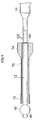
insertion assisting tool 70 from contacting thefirst balloon 42 when the pushing operation shown in Fig. 3E is performed. - Fig. 4 is a schematic view showing a construction of a first embodiment of the contact preventing device.
- A
contact prevention indicator 100 for contact prevention is formed on the outer peripheral surface of theinsertion 12 shown in Fig. 4. Thecontact prevention indicator 100 is formed at the position where it appears from the base end side of theinsertion assisting tool 70 when the tip end of theinsertion assisting tool 70 is in the state in which the tip end of theinsertion assisting tool 70 approaches thefirst balloon 42, but does not contact the first balloon 42 (hereinafter, called a limit state) as shown in Fig. 4. When scales 102 and the like are formed on theinsertion section 12, it is preferable to form thecontact prevention indicator 100 to be different in thickness, color, shape and the like from thescale 102 to be recognized as thecontact prevention indicator 100 at a glance. For example, it is preferable to form thecontact prevention indicator 100 to be thicker than thescale 102 or form it in a different color from thescale 102. - In the first embodiment constructed as described above, when the
insertion assisting tool 70 is pushed to the tip end side of theinsertion section 12 and is brought into the limit state, theindicator 100 appears from the base end side of theinsertion assisting tool 70. Accordingly, the operator recognizes theindicator 100, and thereby, the operator can prevent the tip end of theinsertion assisting tool 70 from contacting thefirst balloon 42. Thereby, thefirst balloon 42 can be prevented from being damaged. - The aforementioned first embodiment is provided with the
indicator 100 indicating the limit state, but other than the indicator, an indicator indicating that the tip end of theinsertion assisting tool 70 approaches the limit state may be provided. This makes it possible to recognize that the tip end of theinsertion assisting tool 70 approaches thefirst balloon 42 stepwise. - In the aforementioned first embodiment, the
contact prevention indicator 100 is formed separately from thescales 102, but thescale 102 corresponding to the position of theindicator 100 may be changed from theother scales 102 in thickness, color, shape and the like. For example, theother scales 102 may be formed in white, and thescale 102 at the position corresponding to thecontact prevention indicator 100 may be formed in red. - Fig. 5 is a schematic view showing a construction of a second embodiment of the contact preventing device.
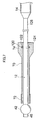
- A string-shaped
member 110 shown in Fig. 5 has its both ends respectively connected to theinsertion assisting tool 70 and thehand operation section 14. As the string-shapedmember 110, a chain, a string or the like, which is not extended in the axial direction is used, and the maximum length of the string-shapedmember 110 is set at the distance between theinsertion assisting tool 70 and thehand operation section 14 in the limit state. It is suitable to connect the both ends of the string-shapedmember 110 to theinsertion assisting tool 70 and thehand operation section 14 after covering the insertion section with theinsertion assisting tool 70. - According to the second embodiment constructed as described above, when the
insertion assisting tool 70 is pushed to the tip end side of theinsertion section 12, the string-shapedmember 110 strains when theinsertion assisting tool 70 is in the limit state, and theinsertion assisting tool 70 cannot be pushed any more. Accordingly, the tip end of theinsertion assisting tool 70 can be prevented from contacting thefirst balloon 42. - In the aforementioned second embodiment, the base end side of the string-shaped
member 110 is connected to thehand operation section 14, but the base end side of the string-shapedmember 110 may be connected to the base end part of theinsertion section 12. - As shown in Fig. 6, an end portion of the string-shaped
member 110 is wound around a take-uproller 112, and thereby, excessive deflection of the string-shapedmember 110 may be removed. The taken-uproller 112 shown in Fig. 6 is provided inside thegripping part 74 of theinsertion assisting tool 70, and is biased in the arrow direction by a biasing device not shown. Accordingly, the string-shapedmember 110 which is loosened between theinsertion assisting tool 70 and theinsertion section 14 is automatically wound by the taken-uproller 112. Therefore, it can be prevented that the loosened string-shapedmember 110 interferes with the operation. The taken-uproller 112 may be provided at thehand operation section 14 side. In the apparatus shown in Fig. 6, the rotational frequency of the taken-uproller 112 is detected, and when the rotational frequency becomes a set value, it is determined as the limit state, and the rotation of the taken-uproller 112 may be stopped. Alternatively, when the rotational frequency becomes the set value, the warning may be sent out. - Fig. 7 is a schematic view showing a construction of a third embodiment of the contact preventing device.
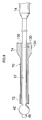
- A recessed groove 120 is formed in an inner peripheral surface of the
insertion assisting tool 70 shown in Fig. 7, and a ring-shapedreflector plate 122 is embedded in and fixed to the recessed groove 120. Thereflector plate 122 is disposed to be detected by anoptical sensor 124 when theinsertion assisting tool 70 is in the limit state. - The
optical sensor 124 is fixed to theinsertion section 12. Theoptical sensor 124 irradiates light from the outer peripheral surface of theinsertion section 12 and receives the reflected light, and thereby, detects the change in the reflected light amount. Accordingly, if thereflector plate 122 is disposed at the outer side of theoptical sensor 124, the reflected light amount changes, and therefore, theoptical sensor 124 can detect thereflector plate 122. - A
cable 126 is connected to theoptical sensor 124, and thecable 126 is connected to theprocessor 30 in Fig. 1. Theprocessor 30 performs warning display on themonitor 60, or issues warning sound from a speaker built in themonitor 60 when theoptical sensor 124 detects thereflector plate 122. - According to the third embodiment constructed as described above, when the
insertion assisting tool 70 is pushed to the tip end side of theinsertion section 12, theoptical sensor 124 detects thereflector plate 122 when theinsertion assisting tool 70 comes to the limit state, and warning sound is issued. Accordingly, the tip end of theinsertion assisting tool 70 can be prevented from contacting thefirst balloon 42. - In the aforementioned third embodiment, the
reflector plate 122 is provided as the detected member to be detected by theoptical sensor 124, but the member to be detected is not limited to this, and may be an indicator for optical detection or the like. - In the aforementioned third embodiment, the
reflector plate 122 is provided at theinsertion assisting tool 70, and theoptical sensor 124 is provided at theinsertion section 12, but in reverse, thereflector plate 122 may be provided at the outer peripheral surface of theinsertion section 12, and theoptical sensor 124 may be provided at an inner peripheral surface of theinsertion assisting tool 70. In this case, it is suitable to provide the display part on the outer peripheral surface of thegripping part 74 of theinsertion assisting tool 70 and display a warning message. - In the aforementioned third embodiment, the
reflector plate 122 is provided at thegripping part 74 at the base end of theinsertion assisting tool 70, but the attaching position of the member to be detected such as thereflector plate 122 is not limited to this. For example, as shown in Fig. 8, thereflector plate 122 may be provided at the tip end of theinsertion assisting tool 70, and theoptical sensor 124 may be placed to detect thereflector plate 122 in the limit state. In this case, the tip end position of theinsertion assisting tool 70 is detected, and therefore, the tip end of theinsertion assisting tool 70 can be more reliably prevented from contacting thefirst balloon 42. - Further, in the aforementioned third embodiment, warning is issued in the limit state, but it can be detected that the tip end of the
insertion assisting tool 70 approaches the limit state by providing a plurality ofreflector plates 122, and warning can be issued. Thereby, stepwise warning can be performed. - Fig. 9 is a schematic view showing a construction of a fourth embodiment of the contact preventing device.
- A
magnetic body 132 is provided inside theinsertion section 12 shown in Fig. 9. Themagnetic body 132 is disposed at the position which is detected by amagnetic sensor 130 which will be described later when theinsertion assisting tool 70 is in the limit state. Themagnetic body 132 is formed into a ring shape, and is disposed in the state in which the content such as the aforementioned light guide and tube is inserted through themagnetic body 132. The shape, construction and the like of themagnetic body 132 are not especially limited, and for example, a magnetic tape or the like may be used. - Meanwhile, the
magnetic sensor 130 is provided at thegripping part 74 of theinsertion assisting tool 70. When themagnetic sensor 130 detects themagnetic body 132, a message of warning is displayed on thedisplay part 134 provided on the outer surface of thegripping part 74. - According to the fourth embodiment constructed as described above, when the
insertion assisting tool 70 is pushed to the tip end side of theinsertion section 12, themagnetic sensor 130 detects themagnetic body 132 and the message of warning is displayed on thedisplay part 134, when theinsertion assisting tool 70 is in the limit state. Accordingly, the tip end of theinsertion assisting tool 70 can be prevented from contacting thefirst balloon 42. - In the aforementioned fourth embodiment, the
magnetic body 132 is provided at theinsertion section 12, and themagnetic sensor 130 is provided at theinsertion assisting tool 70, but in reverse, themagnetic body 132 may be provided at theinsertion assisting tool 70, while themagnetic sensor 130 may be provided at theinsertion section 12. The attaching positions of themagnetic body 132 and themagnetic sensor 130 are not limited to the base end of theinsertion assisting tool 70, but may the tip end of theinsertion assisting tool 70, for example. Thereby, the tip end of theinsertion assisting tool 70 can be prevented from contacting thefirst balloon 42 more reliably. - The aforementioned fourth embodiment is constructed to issue warning in the limit state, but by providing a plurality of
magnetic bodies 132, it may be detected that theinsertion assisting tool 70 approaches the limit state and warning may be issued. Thereby, stepwise warning can be performed. - The aforementioned first to fourth embodiments cite the example of a double balloon type endoscope apparatus with the
first balloon 42 fitted to theinsertion section 12 and thesecond balloon 72 fitted to theinsertion assisting tool 70, but it is suitable if only thefirst balloon 42 is fitted to theinsertion section 12, and the present invention can be also applied to the endoscope apparatus in which thesecond balloon 72 is not fitted to theinsertion assisting tool 70. - The operation methods of the endoscope apparatuses in the aforementioned first to fourth embodiments are not limited to the procedure shown in Fig. 3, and the effect of the present invention can be also obtained by the operation method shown in Fig. 10. Namely, by providing the aforementioned contact preventing device, the
insertion assisting tool 2 can be prevented from contacting thefirst balloon 4 and thefirst balloon 4 can be prevented from being damaged, when theinsertion assisting tool 2 is pushed in along theinsertion section 1 as shown in Fig. 10C. - In the aforementioned third and fourth embodiments, warning is performed when the limit state is detected, but the
insertion assisting tool 70 may be prevented from contacting thefirst balloon 42 by fixing theinsertion part 12 and theinsertion assisting tool 70. For example, the elastic member made of rubber or the like is provided to be able to protrude and retreat with respect to the inner peripheral surface of theinsertion assisting tool 70, and the elastic member is controlled to protrude when the limit sated is detected. Thereby, the elastic member protrudes and abuts to the outer peripheral surface of theinsertion section 12 when theinsertion assisting tool 70 is in the limit state, and theinsertion section 12 and theinsertion assisting tool 70 are fixed. Thereby, theinsertion assisting tool 70 can be reliably prevented from contacting thefirst balloon 42.
Claims (5)
- An endoscope apparatus having an endoscope (10) with an insertion section (12) being connected to a hand operation section (14) and a balloon (42, 72) fitted to the insertion section (12), and an insertion assisting tool (70) which covers the insertion section and guides insertion of the insertion section into a body cavity, characterized by comprising:a contact preventing device which prevents a tip end of the insertion assisting tool (70) from contacting the balloon (42, 72).
- The endoscope apparatus according to claim 1, characterized in that the contact preventing device (100, 102) is an indicator (100) formed at an outer surface of the insertion section (12), and the indicator (100) appears from a base end side of the insertion assisting tool (70) when the insertion assisting tool is relatively moved to a tip end side of the insertion section (12), and the tip end of the insertion assisting tool (70) comes close to the balloon (42, 72).
- The endoscope apparatus according to claim 1, characterized in that the contact preventing device is a string-shaped member (110) which connects the insertion assisting tool (70) and the hand operation section (14).
- The endoscope apparatus according to claim 1, characterized in that the contact preventing device comprises:an optical sensor (124) provided at one of the insertion section (12) and the insertion assisting tool (70);an indicator (122) for optical detection provided at the other one of the insertion section (12) and the insertion assisting tool (70), and detected by the optical sensor (124) when the tip end of the insertion assisting tool (70) comes close to the balloon (42, 72); anda warning device (126, 30, 60) which performs warning when the optical sensor (124) detects the indicator (122).
- The endoscope apparatus according to claim 1, characterized in that the contact preventing device comprises:a magnetic sensor (130) provided at one of the insertion section (12) and the insertion assisting tool (70);a magnetic body (132) provided at the other one of the insertion section (12) and the insertion assisting tool (72), and detected by the magnetic sensor (130) when the tip end of the insertion assisting tool (70) comes close to the balloon (42, 72); anda warning device (134) which performs warning when the magnetic sensor (130) detects the magnetic body (132).
Priority Applications (2)
| Application Number | Priority Date | Filing Date | Title |
|---|---|---|---|
| EP07025046A EP1902667B1 (en) | 2003-12-24 | 2004-12-22 | Endoscope apparatus |
| EP07025045A EP1902666B1 (en) | 2003-12-24 | 2004-12-22 | Endoscope apparatus |
Applications Claiming Priority (2)
| Application Number | Priority Date | Filing Date | Title |
|---|---|---|---|
| JP2003426919A JP3873285B2 (en) | 2003-12-24 | 2003-12-24 | Endoscope device |
| JP2003426919 | 2003-12-24 |
Related Child Applications (2)
| Application Number | Title | Priority Date | Filing Date |
|---|---|---|---|
| EP07025046A Division EP1902667B1 (en) | 2003-12-24 | 2004-12-22 | Endoscope apparatus |
| EP07025045A Division EP1902666B1 (en) | 2003-12-24 | 2004-12-22 | Endoscope apparatus |
Publications (2)
| Publication Number | Publication Date |
|---|---|
| EP1547514A1 true EP1547514A1 (en) | 2005-06-29 |
| EP1547514B1 EP1547514B1 (en) | 2008-08-06 |
Family
ID=34544963
Family Applications (3)
| Application Number | Title | Priority Date | Filing Date |
|---|---|---|---|
| EP04030522A Expired - Lifetime EP1547514B1 (en) | 2003-12-24 | 2004-12-22 | Endoscope apparatus |
| EP07025045A Expired - Lifetime EP1902666B1 (en) | 2003-12-24 | 2004-12-22 | Endoscope apparatus |
| EP07025046A Expired - Lifetime EP1902667B1 (en) | 2003-12-24 | 2004-12-22 | Endoscope apparatus |
Family Applications After (2)
| Application Number | Title | Priority Date | Filing Date |
|---|---|---|---|
| EP07025045A Expired - Lifetime EP1902666B1 (en) | 2003-12-24 | 2004-12-22 | Endoscope apparatus |
| EP07025046A Expired - Lifetime EP1902667B1 (en) | 2003-12-24 | 2004-12-22 | Endoscope apparatus |
Country Status (6)
| Country | Link |
|---|---|
| US (1) | US20050159644A1 (en) |
| EP (3) | EP1547514B1 (en) |
| JP (1) | JP3873285B2 (en) |
| CN (4) | CN100536758C (en) |
| AT (3) | ATE427066T1 (en) |
| DE (3) | DE602004015558D1 (en) |
Cited By (3)
| Publication number | Priority date | Publication date | Assignee | Title |
|---|---|---|---|---|
| WO2007062632A1 (en) * | 2005-11-30 | 2007-06-07 | Philipps-Universität Marburg | Arrangement for guiding instruments in cavities |
| CN104644260A (en) * | 2014-09-12 | 2015-05-27 | 密雷 | Polypus base water injection system for minimally invasive gallbladder remaining surgery |
| US10335243B2 (en) | 2015-06-01 | 2019-07-02 | Olympus Corporation | Drape unit |
Families Citing this family (51)
| Publication number | Priority date | Publication date | Assignee | Title |
|---|---|---|---|---|
| US8784336B2 (en) | 2005-08-24 | 2014-07-22 | C. R. Bard, Inc. | Stylet apparatuses and methods of manufacture |
| JP4683282B2 (en) * | 2005-08-31 | 2011-05-18 | 富士フイルム株式会社 | Endoscope device |
| CN101355901B (en) * | 2005-11-08 | 2011-10-05 | 纽约市哥伦比亚大学理事会 | Devices and methods for delivering one or more deliverables into the body |
| US20070148890A1 (en) * | 2005-12-27 | 2007-06-28 | Enicks Darwin G | Oxygen enhanced metastable silicon germanium film layer |
| US7794407B2 (en) | 2006-10-23 | 2010-09-14 | Bard Access Systems, Inc. | Method of locating the tip of a central venous catheter |
| US8388546B2 (en) | 2006-10-23 | 2013-03-05 | Bard Access Systems, Inc. | Method of locating the tip of a central venous catheter |
| US8105230B2 (en) * | 2007-07-09 | 2012-01-31 | Olympus Medical Systems Corp. | Medical system |
| US8157727B2 (en) * | 2007-07-16 | 2012-04-17 | Ethicon Endo-Surgery, Inc. | Surgical methods and devices with movement assistance |
| US9521961B2 (en) | 2007-11-26 | 2016-12-20 | C. R. Bard, Inc. | Systems and methods for guiding a medical instrument |
| US9649048B2 (en) | 2007-11-26 | 2017-05-16 | C. R. Bard, Inc. | Systems and methods for breaching a sterile field for intravascular placement of a catheter |
| ES2557084T3 (en) | 2007-11-26 | 2016-01-21 | C. R. Bard, Inc. | Integrated system for intravascular catheter placement |
| US10449330B2 (en) | 2007-11-26 | 2019-10-22 | C. R. Bard, Inc. | Magnetic element-equipped needle assemblies |
| US8849382B2 (en) * | 2007-11-26 | 2014-09-30 | C. R. Bard, Inc. | Apparatus and display methods relating to intravascular placement of a catheter |
| US10524691B2 (en) | 2007-11-26 | 2020-01-07 | C. R. Bard, Inc. | Needle assembly including an aligned magnetic element |
| US9492097B2 (en) | 2007-11-26 | 2016-11-15 | C. R. Bard, Inc. | Needle length determination and calibration for insertion guidance system |
| US8781555B2 (en) | 2007-11-26 | 2014-07-15 | C. R. Bard, Inc. | System for placement of a catheter including a signal-generating stylet |
| US10751509B2 (en) | 2007-11-26 | 2020-08-25 | C. R. Bard, Inc. | Iconic representations for guidance of an indwelling medical device |
| US8478382B2 (en) | 2008-02-11 | 2013-07-02 | C. R. Bard, Inc. | Systems and methods for positioning a catheter |
| ES2525525T3 (en) | 2008-08-22 | 2014-12-26 | C.R. Bard, Inc. | Catheter assembly that includes ECG and magnetic sensor assemblies |
| US8437833B2 (en) | 2008-10-07 | 2013-05-07 | Bard Access Systems, Inc. | Percutaneous magnetic gastrostomy |
| US9532724B2 (en) | 2009-06-12 | 2017-01-03 | Bard Access Systems, Inc. | Apparatus and method for catheter navigation using endovascular energy mapping |
| US9339206B2 (en) | 2009-06-12 | 2016-05-17 | Bard Access Systems, Inc. | Adaptor for endovascular electrocardiography |
| EP2464407A4 (en) | 2009-08-10 | 2014-04-02 | Bard Access Systems Inc | DEVICES AND METHODS FOR ENDOVASCULAR ELECTROGRAPHY |
| CN102665541B (en) | 2009-09-29 | 2016-01-13 | C·R·巴德股份有限公司 | The probe used together with the equipment that the Ink vessel transfusing for conduit is placed |
| WO2011044421A1 (en) | 2009-10-08 | 2011-04-14 | C. R. Bard, Inc. | Spacers for use with an ultrasound probe |
| WO2011097312A1 (en) | 2010-02-02 | 2011-08-11 | C.R. Bard, Inc. | Apparatus and method for catheter navigation and tip location |
| CN103037761B (en) | 2010-05-28 | 2016-11-02 | C·R·巴德股份有限公司 | Insertion guide systems for needles and medical components |
| EP2912999B1 (en) | 2010-05-28 | 2022-06-29 | C. R. Bard, Inc. | Apparatus for use with needle insertion guidance system |
| JP5027343B2 (en) | 2010-07-09 | 2012-09-19 | オリンパスメディカルシステムズ株式会社 | Endoscope holding device and endoscope system |
| EP2603145A2 (en) | 2010-08-09 | 2013-06-19 | C.R. Bard, Inc. | Support and cover structures for an ultrasound probe head |
| JP5845260B2 (en) | 2010-08-20 | 2016-01-20 | シー・アール・バード・インコーポレーテッドC R Bard Incorporated | Reconfirmation of ECG support catheter tip placement |
| WO2012058461A1 (en) | 2010-10-29 | 2012-05-03 | C.R.Bard, Inc. | Bioimpedance-assisted placement of a medical device |
| USD699359S1 (en) | 2011-08-09 | 2014-02-11 | C. R. Bard, Inc. | Ultrasound probe head |
| USD724745S1 (en) | 2011-08-09 | 2015-03-17 | C. R. Bard, Inc. | Cap for an ultrasound probe |
| WO2013070775A1 (en) | 2011-11-07 | 2013-05-16 | C.R. Bard, Inc | Ruggedized ultrasound hydrogel insert |
| US20130269705A1 (en) | 2012-04-16 | 2013-10-17 | Thomas C. Kochem | Variable stiffness flexure |
| CN104837413B (en) | 2012-06-15 | 2018-09-11 | C·R·巴德股份有限公司 | Apparatus and method for detecting removable caps on ultrasound probes |
| US9333111B2 (en) | 2013-02-04 | 2016-05-10 | Hologic, Inc. | Fundus bumper mechanical reference for easier mechanism deployment |
| US9895192B2 (en) | 2013-03-13 | 2018-02-20 | Hologic, Inc. | Intrauterine treatment device with articulating array |
| US20140276234A1 (en) * | 2013-03-13 | 2014-09-18 | Hologic, Inc. | Intrauterine measurement device |
| CN105979868B (en) | 2014-02-06 | 2020-03-10 | C·R·巴德股份有限公司 | Systems and methods for guidance and placement of endovascular devices |
| US10973584B2 (en) | 2015-01-19 | 2021-04-13 | Bard Access Systems, Inc. | Device and method for vascular access |
| JP6368256B2 (en) * | 2015-02-05 | 2018-08-01 | 富士フイルム株式会社 | Endoscope system |
| US11553832B2 (en) * | 2015-06-05 | 2023-01-17 | Fujifilm Corporation | Endoscope system |
| WO2016203803A1 (en) * | 2015-06-18 | 2016-12-22 | オリンパス株式会社 | Insertion apparatus and insertion device |
| WO2016210325A1 (en) | 2015-06-26 | 2016-12-29 | C.R. Bard, Inc. | Connector interface for ecg-based catheter positioning system |
| US11000207B2 (en) | 2016-01-29 | 2021-05-11 | C. R. Bard, Inc. | Multiple coil system for tracking a medical device |
| US10939814B2 (en) * | 2016-08-19 | 2021-03-09 | Jason Andrew Slate | Systems and method for preventing air escape and maintaining air distension |
| EP3852622B1 (en) | 2018-10-16 | 2025-04-02 | Bard Access Systems, Inc. | Safety-equipped connection systems and methods thereof for establishing electrical connections |
| CN113473916A (en) | 2019-01-30 | 2021-10-01 | 巴德阿克塞斯系统股份有限公司 | System and method for tracking medical devices |
| EP4298985A4 (en) * | 2021-02-25 | 2024-07-24 | FUJIFILM Corporation | Medical instrument guiding device and endoscope device |
Citations (4)
| Publication number | Priority date | Publication date | Assignee | Title |
|---|---|---|---|---|
| US4040413A (en) * | 1974-07-18 | 1977-08-09 | Fuji Photo Optical Co. Ltd. | Endoscope |
| JPH0663045A (en) * | 1992-08-20 | 1994-03-08 | Olympus Optical Co Ltd | Ultrasonic endoscope |
| JPH11290263A (en) * | 1998-04-13 | 1999-10-26 | Hironori Yamamoto | Endoscope mounting balloon used for mounting digestive tract endoscopy, sliding tube with balloon, and use thereof |
| JP2002301019A (en) * | 2001-04-09 | 2002-10-15 | Hironori Yamamoto | Endoscope |
Family Cites Families (9)
| Publication number | Priority date | Publication date | Assignee | Title |
|---|---|---|---|---|
| JPS506192A (en) * | 1973-05-18 | 1975-01-22 | ||
| US5353787A (en) * | 1993-06-10 | 1994-10-11 | Price Evelyn C | Endotracheal tube and oral airway connector |
| US5709691A (en) * | 1996-03-11 | 1998-01-20 | Morejon; Orlando | Endotracheal tube cleaning device |
| US5928137A (en) * | 1996-05-03 | 1999-07-27 | Green; Philip S. | System and method for endoscopic imaging and endosurgery |
| JPH11287957A (en) * | 1998-04-01 | 1999-10-19 | Olympus Optical Co Ltd | Rough fine movement deriving device |
| AU1442500A (en) * | 1998-10-05 | 2000-04-26 | Scimed Life Systems, Inc. | Large area thermal ablation |
| JP3596661B2 (en) * | 1999-02-22 | 2004-12-02 | 富士写真光機株式会社 | Endoscope insertion aid |
| US6632227B2 (en) * | 2001-08-24 | 2003-10-14 | Scimed Life Systems, Inc. | Endoscopic resection devices |
| US20040068190A1 (en) * | 2002-10-04 | 2004-04-08 | Cespedes Eduardo Ignacio | Imaging catheter with indicia and methods of use |
-
2003
- 2003-12-24 JP JP2003426919A patent/JP3873285B2/en not_active Expired - Lifetime
-
2004
- 2004-12-22 DE DE602004015558T patent/DE602004015558D1/en not_active Expired - Lifetime
- 2004-12-22 AT AT07025046T patent/ATE427066T1/en not_active IP Right Cessation
- 2004-12-22 DE DE602004020406T patent/DE602004020406D1/en not_active Expired - Lifetime
- 2004-12-22 DE DE602004019592T patent/DE602004019592D1/en not_active Expired - Lifetime
- 2004-12-22 EP EP04030522A patent/EP1547514B1/en not_active Expired - Lifetime
- 2004-12-22 EP EP07025045A patent/EP1902666B1/en not_active Expired - Lifetime
- 2004-12-22 AT AT07025045T patent/ATE422837T1/en not_active IP Right Cessation
- 2004-12-22 EP EP07025046A patent/EP1902667B1/en not_active Expired - Lifetime
- 2004-12-22 AT AT04030522T patent/ATE403393T1/en not_active IP Right Cessation
- 2004-12-23 CN CN200710141639.1A patent/CN100536758C/en not_active Expired - Lifetime
- 2004-12-23 US US11/019,514 patent/US20050159644A1/en not_active Abandoned
- 2004-12-23 CN CN200710141637.2A patent/CN100515316C/en not_active Expired - Lifetime
- 2004-12-23 CN CNB2004101045538A patent/CN100361622C/en not_active Expired - Lifetime
- 2004-12-23 CN CN200710141638.7A patent/CN101099660B/en not_active Expired - Lifetime
Patent Citations (4)
| Publication number | Priority date | Publication date | Assignee | Title |
|---|---|---|---|---|
| US4040413A (en) * | 1974-07-18 | 1977-08-09 | Fuji Photo Optical Co. Ltd. | Endoscope |
| JPH0663045A (en) * | 1992-08-20 | 1994-03-08 | Olympus Optical Co Ltd | Ultrasonic endoscope |
| JPH11290263A (en) * | 1998-04-13 | 1999-10-26 | Hironori Yamamoto | Endoscope mounting balloon used for mounting digestive tract endoscopy, sliding tube with balloon, and use thereof |
| JP2002301019A (en) * | 2001-04-09 | 2002-10-15 | Hironori Yamamoto | Endoscope |
Non-Patent Citations (3)
| Title |
|---|
| PATENT ABSTRACTS OF JAPAN vol. 018, no. 301 (C - 1210) 9 June 1994 (1994-06-09) * |
| PATENT ABSTRACTS OF JAPAN vol. 2000, no. 01 31 January 2000 (2000-01-31) * |
| PATENT ABSTRACTS OF JAPAN vol. 2003, no. 02 5 February 2003 (2003-02-05) * |
Cited By (3)
| Publication number | Priority date | Publication date | Assignee | Title |
|---|---|---|---|---|
| WO2007062632A1 (en) * | 2005-11-30 | 2007-06-07 | Philipps-Universität Marburg | Arrangement for guiding instruments in cavities |
| CN104644260A (en) * | 2014-09-12 | 2015-05-27 | 密雷 | Polypus base water injection system for minimally invasive gallbladder remaining surgery |
| US10335243B2 (en) | 2015-06-01 | 2019-07-02 | Olympus Corporation | Drape unit |
Also Published As
| Publication number | Publication date |
|---|---|
| CN101099660A (en) | 2008-01-09 |
| US20050159644A1 (en) | 2005-07-21 |
| ATE403393T1 (en) | 2008-08-15 |
| EP1902666A1 (en) | 2008-03-26 |
| CN101099661A (en) | 2008-01-09 |
| JP3873285B2 (en) | 2007-01-24 |
| DE602004020406D1 (en) | 2009-05-14 |
| CN100515316C (en) | 2009-07-22 |
| CN101099660B (en) | 2010-07-21 |
| EP1547514B1 (en) | 2008-08-06 |
| EP1902666B1 (en) | 2009-02-18 |
| EP1902667A1 (en) | 2008-03-26 |
| ATE427066T1 (en) | 2009-04-15 |
| JP2005185309A (en) | 2005-07-14 |
| CN100536758C (en) | 2009-09-09 |
| EP1902667B1 (en) | 2009-04-01 |
| ATE422837T1 (en) | 2009-03-15 |
| CN1636503A (en) | 2005-07-13 |
| DE602004019592D1 (en) | 2009-04-02 |
| DE602004015558D1 (en) | 2008-09-18 |
| CN101112302A (en) | 2008-01-30 |
| CN100361622C (en) | 2008-01-16 |
Similar Documents
| Publication | Publication Date | Title |
|---|---|---|
| EP1902667B1 (en) | Endoscope apparatus | |
| EP1726250B1 (en) | Double-balloon endoscope system | |
| US20100286479A1 (en) | Internal pressure detecting device for inflating and deflating member and endoscope apparatus | |
| US20150112138A1 (en) | Hood for endoscope, endoscope and method of fixing balloon for endoscope | |
| JP2007282712A (en) | Balloon unit for endoscopic instrument | |
| EP1844700B1 (en) | Endoscope with balloon | |
| JP4836653B2 (en) | Endoscope device | |
| JP2007014475A (en) | Balloon control device for endoscope apparatus | |
| JP4517252B2 (en) | Endoscope device | |
| JP3874292B2 (en) | Endoscope device | |
| WO2021176530A1 (en) | Endoscope hood and endoscope system | |
| JP2005185706A (en) | Endoscope | |
| JP4683282B2 (en) | Endoscope device | |
| JP3873284B2 (en) | Endoscope device | |
| JP4578862B2 (en) | Medical system | |
| JP4348484B2 (en) | Endoscope device | |
| JP3800223B2 (en) | Endoscope device | |
| JP2007111542A (en) | Endoscope apparatus | |
| JP2005118374A (en) | Endoscope and insertion assist of endoscope | |
| JPH07299069A (en) | Ultrasound endoscope | |
| JP2008023102A (en) | Endoscope |
Legal Events
| Date | Code | Title | Description |
|---|---|---|---|
| PUAI | Public reference made under article 153(3) epc to a published international application that has entered the european phase |
Free format text: ORIGINAL CODE: 0009012 |
|
| AK | Designated contracting states |
Kind code of ref document: A1 Designated state(s): AT BE BG CH CY CZ DE DK EE ES FI FR GB GR HU IE IS IT LI LT LU MC NL PL PT RO SE SI SK TR |
|
| AX | Request for extension of the european patent |
Extension state: AL BA HR LV MK YU |
|
| 17P | Request for examination filed |
Effective date: 20050617 |
|
| RAP1 | Party data changed (applicant data changed or rights of an application transferred) |
Owner name: SRJ CORPORATION Owner name: FUJINON CORPORATION |
|
| AKX | Designation fees paid |
Designated state(s): AT BE BG CH CY CZ DE DK EE ES FI FR GB GR HU IE IS IT LI LT LU MC NL PL PT RO SE SI SK TR |
|
| 17Q | First examination report despatched |
Effective date: 20061211 |
|
| GRAP | Despatch of communication of intention to grant a patent |
Free format text: ORIGINAL CODE: EPIDOSNIGR1 |
|
| RIN1 | Information on inventor provided before grant (corrected) |
Inventor name: TAKANO, MASAYUKI |
|
| RIN1 | Information on inventor provided before grant (corrected) |
Inventor name: YAMAMOTO, HIRONORI Inventor name: TAKANO, MASAYUKI |
|
| RIN1 | Information on inventor provided before grant (corrected) |
Inventor name: TAKANO, MASAYUKI |
|
| GRAS | Grant fee paid |
Free format text: ORIGINAL CODE: EPIDOSNIGR3 |
|
| GRAA | (expected) grant |
Free format text: ORIGINAL CODE: 0009210 |
|
| AK | Designated contracting states |
Kind code of ref document: B1 Designated state(s): AT BE BG CH CY CZ DE DK EE ES FI FR GB GR HU IE IS IT LI LT LU MC NL PL PT RO SE SI SK TR |
|
| REG | Reference to a national code |
Ref country code: GB Ref legal event code: FG4D |
|
| REG | Reference to a national code |
Ref country code: CH Ref legal event code: EP |
|
| REG | Reference to a national code |
Ref country code: IE Ref legal event code: FG4D |
|
| REF | Corresponds to: |
Ref document number: 602004015558 Country of ref document: DE Date of ref document: 20080918 Kind code of ref document: P |
|
| PG25 | Lapsed in a contracting state [announced via postgrant information from national office to epo] |
Ref country code: NL Free format text: LAPSE BECAUSE OF FAILURE TO SUBMIT A TRANSLATION OF THE DESCRIPTION OR TO PAY THE FEE WITHIN THE PRESCRIBED TIME-LIMIT Effective date: 20080806 Ref country code: LT Free format text: LAPSE BECAUSE OF FAILURE TO SUBMIT A TRANSLATION OF THE DESCRIPTION OR TO PAY THE FEE WITHIN THE PRESCRIBED TIME-LIMIT Effective date: 20080806 Ref country code: IS Free format text: LAPSE BECAUSE OF FAILURE TO SUBMIT A TRANSLATION OF THE DESCRIPTION OR TO PAY THE FEE WITHIN THE PRESCRIBED TIME-LIMIT Effective date: 20081206 Ref country code: ES Free format text: LAPSE BECAUSE OF FAILURE TO SUBMIT A TRANSLATION OF THE DESCRIPTION OR TO PAY THE FEE WITHIN THE PRESCRIBED TIME-LIMIT Effective date: 20081117 |
|
| PG25 | Lapsed in a contracting state [announced via postgrant information from national office to epo] |
Ref country code: AT Free format text: LAPSE BECAUSE OF FAILURE TO SUBMIT A TRANSLATION OF THE DESCRIPTION OR TO PAY THE FEE WITHIN THE PRESCRIBED TIME-LIMIT Effective date: 20080806 Ref country code: SI Free format text: LAPSE BECAUSE OF FAILURE TO SUBMIT A TRANSLATION OF THE DESCRIPTION OR TO PAY THE FEE WITHIN THE PRESCRIBED TIME-LIMIT Effective date: 20080806 Ref country code: FI Free format text: LAPSE BECAUSE OF FAILURE TO SUBMIT A TRANSLATION OF THE DESCRIPTION OR TO PAY THE FEE WITHIN THE PRESCRIBED TIME-LIMIT Effective date: 20080806 |
|
| PG25 | Lapsed in a contracting state [announced via postgrant information from national office to epo] |
Ref country code: BE Free format text: LAPSE BECAUSE OF FAILURE TO SUBMIT A TRANSLATION OF THE DESCRIPTION OR TO PAY THE FEE WITHIN THE PRESCRIBED TIME-LIMIT Effective date: 20080806 |
|
| PG25 | Lapsed in a contracting state [announced via postgrant information from national office to epo] |
Ref country code: DK Free format text: LAPSE BECAUSE OF FAILURE TO SUBMIT A TRANSLATION OF THE DESCRIPTION OR TO PAY THE FEE WITHIN THE PRESCRIBED TIME-LIMIT Effective date: 20080806 Ref country code: BG Free format text: LAPSE BECAUSE OF FAILURE TO SUBMIT A TRANSLATION OF THE DESCRIPTION OR TO PAY THE FEE WITHIN THE PRESCRIBED TIME-LIMIT Effective date: 20081106 |
|
| PG25 | Lapsed in a contracting state [announced via postgrant information from national office to epo] |
Ref country code: RO Free format text: LAPSE BECAUSE OF FAILURE TO SUBMIT A TRANSLATION OF THE DESCRIPTION OR TO PAY THE FEE WITHIN THE PRESCRIBED TIME-LIMIT Effective date: 20080806 Ref country code: CZ Free format text: LAPSE BECAUSE OF FAILURE TO SUBMIT A TRANSLATION OF THE DESCRIPTION OR TO PAY THE FEE WITHIN THE PRESCRIBED TIME-LIMIT Effective date: 20080806 Ref country code: PT Free format text: LAPSE BECAUSE OF FAILURE TO SUBMIT A TRANSLATION OF THE DESCRIPTION OR TO PAY THE FEE WITHIN THE PRESCRIBED TIME-LIMIT Effective date: 20090106 Ref country code: SK Free format text: LAPSE BECAUSE OF FAILURE TO SUBMIT A TRANSLATION OF THE DESCRIPTION OR TO PAY THE FEE WITHIN THE PRESCRIBED TIME-LIMIT Effective date: 20080806 |
|
| PLBE | No opposition filed within time limit |
Free format text: ORIGINAL CODE: 0009261 |
|
| STAA | Information on the status of an ep patent application or granted ep patent |
Free format text: STATUS: NO OPPOSITION FILED WITHIN TIME LIMIT |
|
| 26N | No opposition filed |
Effective date: 20090507 |
|
| PG25 | Lapsed in a contracting state [announced via postgrant information from national office to epo] |
Ref country code: MC Free format text: LAPSE BECAUSE OF NON-PAYMENT OF DUE FEES Effective date: 20081231 Ref country code: EE Free format text: LAPSE BECAUSE OF FAILURE TO SUBMIT A TRANSLATION OF THE DESCRIPTION OR TO PAY THE FEE WITHIN THE PRESCRIBED TIME-LIMIT Effective date: 20080806 |
|
| REG | Reference to a national code |
Ref country code: CH Ref legal event code: PL |
|
| PG25 | Lapsed in a contracting state [announced via postgrant information from national office to epo] |
Ref country code: IT Free format text: LAPSE BECAUSE OF FAILURE TO SUBMIT A TRANSLATION OF THE DESCRIPTION OR TO PAY THE FEE WITHIN THE PRESCRIBED TIME-LIMIT Effective date: 20080806 |
|
| REG | Reference to a national code |
Ref country code: IE Ref legal event code: MM4A |
|
| REG | Reference to a national code |
Ref country code: GB Ref legal event code: 732E Free format text: REGISTERED BETWEEN 20091001 AND 20091007 |
|
| PG25 | Lapsed in a contracting state [announced via postgrant information from national office to epo] |
Ref country code: CH Free format text: LAPSE BECAUSE OF NON-PAYMENT OF DUE FEES Effective date: 20081231 Ref country code: LI Free format text: LAPSE BECAUSE OF NON-PAYMENT OF DUE FEES Effective date: 20081231 Ref country code: IE Free format text: LAPSE BECAUSE OF NON-PAYMENT OF DUE FEES Effective date: 20081222 |
|
| REG | Reference to a national code |
Ref country code: FR Ref legal event code: TQ |
|
| PG25 | Lapsed in a contracting state [announced via postgrant information from national office to epo] |
Ref country code: SE Free format text: LAPSE BECAUSE OF FAILURE TO SUBMIT A TRANSLATION OF THE DESCRIPTION OR TO PAY THE FEE WITHIN THE PRESCRIBED TIME-LIMIT Effective date: 20081106 |
|
| PG25 | Lapsed in a contracting state [announced via postgrant information from national office to epo] |
Ref country code: PL Free format text: LAPSE BECAUSE OF FAILURE TO SUBMIT A TRANSLATION OF THE DESCRIPTION OR TO PAY THE FEE WITHIN THE PRESCRIBED TIME-LIMIT Effective date: 20080806 |
|
| PG25 | Lapsed in a contracting state [announced via postgrant information from national office to epo] |
Ref country code: CY Free format text: LAPSE BECAUSE OF FAILURE TO SUBMIT A TRANSLATION OF THE DESCRIPTION OR TO PAY THE FEE WITHIN THE PRESCRIBED TIME-LIMIT Effective date: 20080806 Ref country code: LU Free format text: LAPSE BECAUSE OF NON-PAYMENT OF DUE FEES Effective date: 20081222 Ref country code: HU Free format text: LAPSE BECAUSE OF FAILURE TO SUBMIT A TRANSLATION OF THE DESCRIPTION OR TO PAY THE FEE WITHIN THE PRESCRIBED TIME-LIMIT Effective date: 20090207 |
|
| PG25 | Lapsed in a contracting state [announced via postgrant information from national office to epo] |
Ref country code: TR Free format text: LAPSE BECAUSE OF FAILURE TO SUBMIT A TRANSLATION OF THE DESCRIPTION OR TO PAY THE FEE WITHIN THE PRESCRIBED TIME-LIMIT Effective date: 20080806 |
|
| PG25 | Lapsed in a contracting state [announced via postgrant information from national office to epo] |
Ref country code: GR Free format text: LAPSE BECAUSE OF FAILURE TO SUBMIT A TRANSLATION OF THE DESCRIPTION OR TO PAY THE FEE WITHIN THE PRESCRIBED TIME-LIMIT Effective date: 20081107 |
|
| REG | Reference to a national code |
Ref country code: FR Ref legal event code: PLFP Year of fee payment: 12 |
|
| REG | Reference to a national code |
Ref country code: FR Ref legal event code: PLFP Year of fee payment: 13 |
|
| REG | Reference to a national code |
Ref country code: FR Ref legal event code: PLFP Year of fee payment: 14 |
|
| PGFP | Annual fee paid to national office [announced via postgrant information from national office to epo] |
Ref country code: GB Payment date: 20231102 Year of fee payment: 20 |
|
| PGFP | Annual fee paid to national office [announced via postgrant information from national office to epo] |
Ref country code: FR Payment date: 20231108 Year of fee payment: 20 Ref country code: DE Payment date: 20231031 Year of fee payment: 20 |
|
| REG | Reference to a national code |
Ref country code: DE Ref legal event code: R071 Ref document number: 602004015558 Country of ref document: DE |
|
| REG | Reference to a national code |
Ref country code: GB Ref legal event code: PE20 Expiry date: 20241221 |
|
| PG25 | Lapsed in a contracting state [announced via postgrant information from national office to epo] |
Ref country code: GB Free format text: LAPSE BECAUSE OF EXPIRATION OF PROTECTION Effective date: 20241221 |
|
| PG25 | Lapsed in a contracting state [announced via postgrant information from national office to epo] |
Ref country code: GB Free format text: LAPSE BECAUSE OF EXPIRATION OF PROTECTION Effective date: 20241221 |