EP1547216B1 - High power semiconductor laser diode and method for making such a diode - Google Patents
High power semiconductor laser diode and method for making such a diode Download PDFInfo
- Publication number
- EP1547216B1 EP1547216B1 EP03797442A EP03797442A EP1547216B1 EP 1547216 B1 EP1547216 B1 EP 1547216B1 EP 03797442 A EP03797442 A EP 03797442A EP 03797442 A EP03797442 A EP 03797442A EP 1547216 B1 EP1547216 B1 EP 1547216B1
- Authority
- EP
- European Patent Office
- Prior art keywords
- laser diode
- cig
- semiconductor body
- layer
- absorption
- Prior art date
- Legal status (The legal status is an assumption and is not a legal conclusion. Google has not performed a legal analysis and makes no representation as to the accuracy of the status listed.)
- Expired - Lifetime
Links
- 239000004065 semiconductor Substances 0.000 title claims description 56
- 238000000034 method Methods 0.000 title claims description 35
- 238000010521 absorption reaction Methods 0.000 claims description 58
- 239000012212 insulator Substances 0.000 claims description 38
- 229920002120 photoresistant polymer Polymers 0.000 claims description 30
- 239000000463 material Substances 0.000 claims description 23
- 238000000151 deposition Methods 0.000 claims description 22
- 230000001629 suppression Effects 0.000 claims description 10
- 229910052581 Si3N4 Inorganic materials 0.000 claims description 9
- VYPSYNLAJGMNEJ-UHFFFAOYSA-N Silicium dioxide Chemical compound O=[Si]=O VYPSYNLAJGMNEJ-UHFFFAOYSA-N 0.000 claims description 8
- GWEVSGVZZGPLCZ-UHFFFAOYSA-N Titan oxide Chemical compound O=[Ti]=O GWEVSGVZZGPLCZ-UHFFFAOYSA-N 0.000 claims description 8
- 239000004020 conductor Substances 0.000 claims description 5
- 238000009413 insulation Methods 0.000 claims description 5
- 229910052804 chromium Inorganic materials 0.000 claims description 4
- 229910052681 coesite Inorganic materials 0.000 claims description 4
- 229910052906 cristobalite Inorganic materials 0.000 claims description 4
- 239000000377 silicon dioxide Substances 0.000 claims description 4
- 229910052682 stishovite Inorganic materials 0.000 claims description 4
- 229910052905 tridymite Inorganic materials 0.000 claims description 4
- 229910001218 Gallium arsenide Inorganic materials 0.000 claims description 3
- 229910052697 platinum Inorganic materials 0.000 claims description 3
- 229910052719 titanium Inorganic materials 0.000 claims description 3
- 229910052737 gold Inorganic materials 0.000 claims 2
- 229910052710 silicon Inorganic materials 0.000 claims 1
- 239000010410 layer Substances 0.000 description 92
- 238000013461 design Methods 0.000 description 25
- 238000005530 etching Methods 0.000 description 22
- 230000008569 process Effects 0.000 description 19
- 238000004519 manufacturing process Methods 0.000 description 18
- 230000003287 optical effect Effects 0.000 description 16
- 238000001465 metallisation Methods 0.000 description 9
- 101100269850 Caenorhabditis elegans mask-1 gene Proteins 0.000 description 6
- 238000007493 shaping process Methods 0.000 description 6
- 230000008878 coupling Effects 0.000 description 5
- 238000010168 coupling process Methods 0.000 description 5
- 238000005859 coupling reaction Methods 0.000 description 5
- 230000008021 deposition Effects 0.000 description 5
- 238000009826 distribution Methods 0.000 description 5
- 238000002474 experimental method Methods 0.000 description 4
- 230000006872 improvement Effects 0.000 description 4
- 230000000873 masking effect Effects 0.000 description 4
- 239000002184 metal Substances 0.000 description 4
- 229910052751 metal Inorganic materials 0.000 description 4
- 238000001020 plasma etching Methods 0.000 description 4
- 230000008901 benefit Effects 0.000 description 3
- 230000015572 biosynthetic process Effects 0.000 description 3
- 238000005240 physical vapour deposition Methods 0.000 description 3
- BSYNRYMUTXBXSQ-UHFFFAOYSA-N Aspirin Chemical compound CC(=O)OC1=CC=CC=C1C(O)=O BSYNRYMUTXBXSQ-UHFFFAOYSA-N 0.000 description 2
- 239000011358 absorbing material Substances 0.000 description 2
- 210000000746 body region Anatomy 0.000 description 2
- 238000005229 chemical vapour deposition Methods 0.000 description 2
- 239000000835 fiber Substances 0.000 description 2
- 238000012986 modification Methods 0.000 description 2
- 230000004048 modification Effects 0.000 description 2
- 238000005457 optimization Methods 0.000 description 2
- 238000001039 wet etching Methods 0.000 description 2
- 229910000980 Aluminium gallium arsenide Inorganic materials 0.000 description 1
- 230000002238 attenuated effect Effects 0.000 description 1
- 230000005540 biological transmission Effects 0.000 description 1
- 230000015556 catabolic process Effects 0.000 description 1
- 230000003247 decreasing effect Effects 0.000 description 1
- 238000006731 degradation reaction Methods 0.000 description 1
- 230000001419 dependent effect Effects 0.000 description 1
- 230000001627 detrimental effect Effects 0.000 description 1
- 238000010438 heat treatment Methods 0.000 description 1
- 239000011810 insulating material Substances 0.000 description 1
- 230000003993 interaction Effects 0.000 description 1
- 230000031700 light absorption Effects 0.000 description 1
- 238000002488 metal-organic chemical vapour deposition Methods 0.000 description 1
- 239000013307 optical fiber Substances 0.000 description 1
- 238000000623 plasma-assisted chemical vapour deposition Methods 0.000 description 1
- 230000005855 radiation Effects 0.000 description 1
- 239000002356 single layer Substances 0.000 description 1
- 239000010421 standard material Substances 0.000 description 1
- 238000012360 testing method Methods 0.000 description 1
Images





Classifications
-
- H—ELECTRICITY
- H01—ELECTRIC ELEMENTS
- H01S—DEVICES USING THE PROCESS OF LIGHT AMPLIFICATION BY STIMULATED EMISSION OF RADIATION [LASER] TO AMPLIFY OR GENERATE LIGHT; DEVICES USING STIMULATED EMISSION OF ELECTROMAGNETIC RADIATION IN WAVE RANGES OTHER THAN OPTICAL
- H01S5/00—Semiconductor lasers
- H01S5/20—Structure or shape of the semiconductor body to guide the optical wave ; Confining structures perpendicular to the optical axis, e.g. index or gain guiding, stripe geometry, broad area lasers, gain tailoring, transverse or lateral reflectors, special cladding structures, MQW barrier reflection layers
- H01S5/22—Structure or shape of the semiconductor body to guide the optical wave ; Confining structures perpendicular to the optical axis, e.g. index or gain guiding, stripe geometry, broad area lasers, gain tailoring, transverse or lateral reflectors, special cladding structures, MQW barrier reflection layers having a ridge or stripe structure
-
- H—ELECTRICITY
- H01—ELECTRIC ELEMENTS
- H01S—DEVICES USING THE PROCESS OF LIGHT AMPLIFICATION BY STIMULATED EMISSION OF RADIATION [LASER] TO AMPLIFY OR GENERATE LIGHT; DEVICES USING STIMULATED EMISSION OF ELECTROMAGNETIC RADIATION IN WAVE RANGES OTHER THAN OPTICAL
- H01S5/00—Semiconductor lasers
- H01S5/04—Processes or apparatus for excitation, e.g. pumping, e.g. by electron beams
- H01S5/042—Electrical excitation ; Circuits therefor
- H01S5/0425—Electrodes, e.g. characterised by the structure
- H01S5/04254—Electrodes, e.g. characterised by the structure characterised by the shape
-
- H—ELECTRICITY
- H01—ELECTRIC ELEMENTS
- H01S—DEVICES USING THE PROCESS OF LIGHT AMPLIFICATION BY STIMULATED EMISSION OF RADIATION [LASER] TO AMPLIFY OR GENERATE LIGHT; DEVICES USING STIMULATED EMISSION OF ELECTROMAGNETIC RADIATION IN WAVE RANGES OTHER THAN OPTICAL
- H01S2301/00—Functional characteristics
- H01S2301/16—Semiconductor lasers with special structural design to influence the modes, e.g. specific multimode
- H01S2301/166—Single transverse or lateral mode
-
- H—ELECTRICITY
- H01—ELECTRIC ELEMENTS
- H01S—DEVICES USING THE PROCESS OF LIGHT AMPLIFICATION BY STIMULATED EMISSION OF RADIATION [LASER] TO AMPLIFY OR GENERATE LIGHT; DEVICES USING STIMULATED EMISSION OF ELECTROMAGNETIC RADIATION IN WAVE RANGES OTHER THAN OPTICAL
- H01S2301/00—Functional characteristics
- H01S2301/17—Semiconductor lasers comprising special layers
- H01S2301/176—Specific passivation layers on surfaces other than the emission facet
-
- H—ELECTRICITY
- H01—ELECTRIC ELEMENTS
- H01S—DEVICES USING THE PROCESS OF LIGHT AMPLIFICATION BY STIMULATED EMISSION OF RADIATION [LASER] TO AMPLIFY OR GENERATE LIGHT; DEVICES USING STIMULATED EMISSION OF ELECTROMAGNETIC RADIATION IN WAVE RANGES OTHER THAN OPTICAL
- H01S5/00—Semiconductor lasers
- H01S5/06—Arrangements for controlling the laser output parameters, e.g. by operating on the active medium
- H01S5/065—Mode locking; Mode suppression; Mode selection ; Self pulsating
- H01S5/0651—Mode control
- H01S5/0653—Mode suppression, e.g. specific multimode
- H01S5/0655—Single transverse or lateral mode emission
-
- H—ELECTRICITY
- H01—ELECTRIC ELEMENTS
- H01S—DEVICES USING THE PROCESS OF LIGHT AMPLIFICATION BY STIMULATED EMISSION OF RADIATION [LASER] TO AMPLIFY OR GENERATE LIGHT; DEVICES USING STIMULATED EMISSION OF ELECTROMAGNETIC RADIATION IN WAVE RANGES OTHER THAN OPTICAL
- H01S5/00—Semiconductor lasers
- H01S5/20—Structure or shape of the semiconductor body to guide the optical wave ; Confining structures perpendicular to the optical axis, e.g. index or gain guiding, stripe geometry, broad area lasers, gain tailoring, transverse or lateral reflectors, special cladding structures, MQW barrier reflection layers
- H01S5/2004—Confining in the direction perpendicular to the layer structure
- H01S5/2018—Optical confinement, e.g. absorbing-, reflecting- or waveguide-layers
- H01S5/2022—Absorbing region or layer parallel to the active layer, e.g. to influence transverse modes
-
- H—ELECTRICITY
- H01—ELECTRIC ELEMENTS
- H01S—DEVICES USING THE PROCESS OF LIGHT AMPLIFICATION BY STIMULATED EMISSION OF RADIATION [LASER] TO AMPLIFY OR GENERATE LIGHT; DEVICES USING STIMULATED EMISSION OF ELECTROMAGNETIC RADIATION IN WAVE RANGES OTHER THAN OPTICAL
- H01S5/00—Semiconductor lasers
- H01S5/20—Structure or shape of the semiconductor body to guide the optical wave ; Confining structures perpendicular to the optical axis, e.g. index or gain guiding, stripe geometry, broad area lasers, gain tailoring, transverse or lateral reflectors, special cladding structures, MQW barrier reflection layers
- H01S5/22—Structure or shape of the semiconductor body to guide the optical wave ; Confining structures perpendicular to the optical axis, e.g. index or gain guiding, stripe geometry, broad area lasers, gain tailoring, transverse or lateral reflectors, special cladding structures, MQW barrier reflection layers having a ridge or stripe structure
- H01S5/2205—Structure or shape of the semiconductor body to guide the optical wave ; Confining structures perpendicular to the optical axis, e.g. index or gain guiding, stripe geometry, broad area lasers, gain tailoring, transverse or lateral reflectors, special cladding structures, MQW barrier reflection layers having a ridge or stripe structure comprising special burying or current confinement layers
- H01S5/2218—Structure or shape of the semiconductor body to guide the optical wave ; Confining structures perpendicular to the optical axis, e.g. index or gain guiding, stripe geometry, broad area lasers, gain tailoring, transverse or lateral reflectors, special cladding structures, MQW barrier reflection layers having a ridge or stripe structure comprising special burying or current confinement layers having special optical properties
- H01S5/2219—Structure or shape of the semiconductor body to guide the optical wave ; Confining structures perpendicular to the optical axis, e.g. index or gain guiding, stripe geometry, broad area lasers, gain tailoring, transverse or lateral reflectors, special cladding structures, MQW barrier reflection layers having a ridge or stripe structure comprising special burying or current confinement layers having special optical properties absorbing
Definitions
- This invention relates to semiconductor laser diodes, in particular to ridge waveguide (RWG) diodes, and a method for making such diodes.
- RWG laser diodes are especially used as pump lasers in fiber optic networks and similar applications since they provide the desired narrow-bandwidth optical radiation with a stable light output power in a given frequency band. Naturally, output power and stability of such laser diodes are of crucial interest.
- the present invention relates to an improved laser diode, the improvement in particular concerning the structure and design of the ridge waveguide; it also relates to a manufacturing process for such a laser diode.
- Coupling light of a semiconductor laser diode into an optical fiber is a central problem within the field of optical networks, in particular when high power transmission/coupling is desired. Due to increasing channel density in DWDM (Dense Wavelength Division Multiplexing) long haul networks, and the power requirements at elevated temperatures in metro networks, maximizing the laser diode's operating light output power is a primary design criterion.
- the useful operating power is mainly limited by a "kink" in the L-I curves, i.e. the light output over current curves, indicating a beam steering in lateral direction. The occurrence of such a kink is influenced by the real refractive index step, the gain profile as well as spatial hole burning and local heating in the laser diode.
- the laser diode suffers at a certain power level from the resonance between the fundamental mode and higher order modes in lateral direction. This has been shown by J. Guthrie et al in "Beam instability in 980nm power lasers: Experiment and Analysis" in IEEE Pot. Tech. Lett. 6(12), 1994, pp. 1409-1411. Generation of higher order modes is highly undesirable since efficient laser to fiber coupling is only possible with the fundamental mode.
- RWG ridge waveguide
- Bowler US patent 6 141 365 describes a semiconductor laser with a kink suppression layer. Reportedly, the latter limits the establishment of higher order lateral modes and thus increases the kink power of the device. Bowler also discloses disposing an optical layer along the optical axis of an RWG laser on both sides of the laser's ridge. However, shape and size of this kink suppression layer is essentially determined by the photoresist mask used to form the ridge. Bowler does not address utilizing the kink suppression layer's shape, thickness, and/or material for any particular purpose apart from general kink suppression. Also, the lasers described by Bowler have output powers of no more than 200 to 300 mW which is insufficient for many of today's technical applications.
- a laser diode according to the invention and its fabrication is defined in claims 1 and 16, 18 - 22 respectively. Further embodiments of the invention are the subject-matter of dependent claims 2 - 15, 17 and 23.
- the principal design idea of the invention is to develop a structure of a high power RWG laser diode which controllably introduces additional optical losses for first and higher order modes, whereas the fundamental (or 0th order) mode experiences only minor influences.
- high order lateral modes e.g. the first order mode
- the lateral extension of the desired fundamental mode is smaller than that of the undesirable first order and higher order modes.
- an absorbing layer can function as a suppression layer for the first and higher order modes, without introducing significant absorption of the fundamental mode.
- the absorption layer can be made of any material in which the imaginary part of the complex index of refraction is not zero for the wavelength in question, i.e. the lasing wavelength.
- the element that discriminates first and higher order modes can be a single layer or contain multiple layers, where at least one layer must have the desired absorption properties. Number and location of these mode-discrimination elements (or Complex Index Guiding, CIG, elements) within the laser diode structure as well as shape and number of layers contained within the element depend on the laser design and have to be individually optimized.
- the improvement achieved by adding CIG elements to a standard RWG structure can be demonstrated.
- the linear power for a laser diode with CIG elements as described is significantly higher than for a similar standard laser diode.
- about 900 mW kink-free light output power was reached at an operating current of around 1.1 A.
- the median linear, i.e. kink-free, power taken over about 700 laser diodes increased by about 25% for laser diode structures containing CIG elements compared to standard diodes.
- the photoresist etching mask already used for ridge etching was employed as mask for RIE etching the insulating layer, similar to the method described by Bowler in US patent 6 141 365, cited above.
- the insulating layer at both sides of the ridge was etched down to the semiconductor.
- the p-contact metallisation (Ti/Pt/Au) was deposited.
- the Ti layer of the metallisation functioned as the optically absorbing layer, i.e. the CIG element, in this case.
- the linear power was increased anywhere from 10% to 20%.
- the efficiency decreased by 10% to 20%, indicating significant absorption of the fundamental mode.
- the design was improved by laterally varying the distance of the CIG elements relative to ridge and herewith the extension of the modes.
- the purpose of this variation is to optimize absorption of higher order modes relative to the fundamental mode and thus optimize linear power and minimize efficiency losses.
- a thin insulating layer was added to the CIG element. This layer is electrically insulating and does not absorb light of the lasing wavelength. It is located between the semiconductor body and the absorption layer.
- the overall absorption now not only depends on the material of the absorption layer and the location of the CIG element, but also on the thickness of this insulating layer, i.e. the vertical distance of the modes from the absorption layer.
- the insulator electrically separates the absorption layer, which is a conductor in the present case, from the semiconductor and thus eliminates the possibility of leaking currents.
- the CIG elements were located at 0, 300, and 600nm distance relative to both sides of the ridge, i.e. measured from ridge etching mask.
- the thin insulating layer here case Si 3 N 4 , was part of the CIG elements for all experiments and had a thickness of about 25nm.
- the linear power of these laser diodes increased by about 25% relative to laser diodes without CIG elements.
- the average efficiency was reduced by about 10% for lasers, where the CIG elements were located right next to the ridge, i.e. at 0nm from ridge etching mask.
- the efficiency was reduced by only about 5%.
- the lateral and vertical far-field showed stable single mode outputs above 900 mW and no lateral beam steering was observed in the whole power range.
- the laser diodes with the improved CIG design were tested under accelerated conditions for stability, failures and degradation.
- the CIG-improved lasers showed stable performance, indicating highly reliable operation. No distinctive features were observed compared to standard laser diodes.
- the operating conditions were 900 mA constant current at 85°C heat sink temperature, 3000 hrs.
- the invention concerns a novel high power ridge waveguide semiconductor laser design containing one or more CIG elements (Complex Index Guiding elements).
- CIG elements consist of at least one layer that absorbs light of the lasing wavelength, but may contain a plurality of absorbing and non-absorbing layers.
- the novel laser exhibits high stability with increased kink power.
- the CIG elements are preferably located to both sides of the ridge along the optical axis. Precise location and shape of the CIG element as well as number and location of layers in the CIG element depend on the laser design and are choosen to achieve maximum efficiency and/or maximum kink power.
- the novel manufacturing process according to the invention allows control of the distance relative to the extension of fundamental and first order modes and hence optimization of increased kink power vs. optical losses.
- Experimental results show an increased kink power of about 25% (median) and very good life-time results.
- the position of the absorbing layer relative to the fundamental mode is rather critical. This is due to the fact that absorption of the first order mode is desired, but absorption of the fundamental mode is undesirable since it results in reduced efficiency.
- the described novel manufacturing method allows control of the distance of the absorbing layer relative to the ridge by a self-aligning process. This optimizes the kink power increase by absorption of the first order mode without significantly loosing efficiency by absorption of the fundamental mode. Since the location of the CIG elements can be defined independently of the ridge and its etching mask, any epitaxial design and any ridge design can be used.
- the fabrication method according to the invention has the further advantage that it does not put limitations on the CIG elements in terms of position, thickness, material and deposition method. Also, the novel method facilitates the introduction of a thin insulating layer underneath the absorbtion layer to electrically separate the semiconductor from the metal and thus avoid leaking currents and to modify the overall absorption.
- Fig. 1 is a schematic representation of the principle influence of an absorbing layer on various modes of an RWG laser diode.
- the upper part of Fig. 1 shows the distribution of the "gain" extending over the lateral extension "x" of an RWG laser diode without and with an absorbing layer, the latter according to the invention (dotted lines).
- an absorbing layer reduces the gain in lateral regions, but not in the center region of the diode.
- Fig. 1 now shows the calculated lateral distribution of the optical energy of the fundamental mode (dotted line) and the first order mode, again over the lateral extension "x" and the vertical extension "y".
- the first order mode shows a significantly different lateral distribution of its optical energy, in particular shows it a much higher level than the fundamental mode (dotted lines) in the laterally more distant regions and a minimum at the center region.
- the invention sets in by providing lateral absorbing layers, appropriately positioned parallel to the waveguide, which significantly suppress the first order mode. This in turn leads to an increase in the linear power of the pump laser device since resonant coupling of the first order mode now occurs at higher power levels.
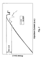
- Fig. 2 illustrates the improvement achieved by adding CIG elements according to the invention to the RWG laser diode structure.
- the figure shows the P-I curve, i.e. power versus injected current in arbitrary units (a.u.), for a standard diode compared to a CIG-improved diode.
- Indicated is the first occurring kink, i.e. instability of the optical output power of a standard diode vs. a CIG-improved diode.
- the first kink clearly occurs at a much lower power level for the standard diode than for the same diode comprising CIG elements.
- stable output powers of more than 900 mW were achieved with the improved CIG design with good life test results.
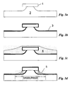
- Fig. 3a starts with the ridge formation by a wet etching process.
- the part of a semiconductor body 2 which is supposed to form the ridge of the final RWG laser diode is covered by a photoresist mask 1, the ridge etching mask.
- GaAs or AlGaAs are the preferred materials for the body 2.
- the etching step results in a semiconductor body 2 having the shape shown in Fig. 3a, i.e. the ridge is formed.
- the shape results from a wet etching process, but the CIG element formation process will work as well on other ridge shapes having, e.g. straight side walls or sidewalls of other shapes.
- Important for the later described CIG layer self-aligned masking process is only the presence of some kind of a mesa structure.
- the deposition can be achieved by a PECVD process, i.e. by Physically Enhanced Chemical Vapor Deposition.
- the thickness of this insulator layer 3 is in the region of 200 to 300 nm, preferably about 220 nm.
- the insulator layer 3 can also be made of alternative materials, such as SiO 2 , AIN, or TiO 2 , and be deposited by alternative deposition methods, such as PVD, i.e. Physical Vapor Deposition, or CVD, i.e. Chemical Vapour Deposition.
- Figs. 3c to 3g produce the mask that defines the location of the absorbing CIG elements. It is effectively the thick Si 3 N 4 insulator layer 3 that acts as a mask for the desired absorbing layer. This insulator layer optically separates the light generated in the waveguide from the absorbing layer. In the regions with thick Si 3 N 4 , any absorbing layer deposited on top will not (or only marginally) contribute to the absorption.
- a photoresist layer 4 is deposited over the whole semiconductor body 2, including insulator layer 3 and mask 1.
- the photoresist is spun over the semiconductor body 2, resulting in a thicker photoresist layer near the ridge and a thinner photoresist layer in the body region.
- the thickness of the resulting photoresist layer 4 is preferably about 2.5 ⁇ m in the region of the ridge and about 1 ⁇ m in the body region.
- the thickness gradient of the photoresist layer 4 is important for the variability of the absorbing layer (or CIG element) location and shape, as will be shown later.
- the photoresist deposition of Fig. 3c prepares the device for the subsequent Si 3 N 4 masking.
- the photoresist is etched to a desired shape, here specifically a variable width or distance, measured from the ridge center.
- a preferred method for this shaping step is RIE, i.e. Reactive Ion Etching. This results in the shaping masks 5 illustrated in Fig. 3d.
- the control of the width of this shaping mask may be facilitated by a rather directional etching process and/or the choice of an appropriate etch time. A person skilled in the art will know how to modify the etching process in order to achieve the desired result.
- Fig. 3d shows three different masks: a narrow one, essentially of the same width as the ridge etching photoresist mask 1; a middle one, somewhat wider than said ridge etching mask 1; and a wide one, identified by the outermost line shown in Fig. 3d. All three widths are shown to clearly demonstrate the variability of the mask.
- the insulator layer 3 established earlier as described above with Fig. 3b, is etched down to the semiconductor body 2.
- the insulator layer 3 remains only at the flanks of the ridge and underneath the photoresist mask which was established in the previous step (Fig. 3d) and forms the insulator strips 6a and 6b on both sides of the ridge. They extend preferably along the whole length of the semiconductor body 2, but may be shorter than the latter if desired.
- the total width of the insulator strips 6a and 6b varies with the width of the shaping mask 5.
- the shape of the insulator strips also determines the effective location of the CIG element, i.e. the location where absorption of light mainly occurs.
- the photoresist shaping mask 5 used for the Si 3 N 4 or any similar etching as well as the ridge etching photoresist mask 1 are removed, e.g. by lift-off.
- the result is illustrated in Fig. 3f.
- a layer of optically absorbing material resulting in an uninterupted layer covering the whole semiconductor body 2 is deposited.
- This layer has two functions :
- this absorption layer must have two important material properties:
- Fig. 3h shows the nearly complete RWG laser diode structure having the additional P-contact layers 9 deposited necessary for electrical powering of the diode.
- Fig. 3i finally shows, somewhat similar to Fig. 1, the optical power distribution of the RWG laser diode shown in Fig. 3h approximately in relative dimensions to the structure in Fig. 3h. It is clearly visible that the fundamental mode has its usual peak in the center of the laser diode, whereas the first order mode - as any higher order modes - extend further into the areas where the CIG elements are located. Thus, the first and higher modes are strongly attenuated, which is what the invention intends to achieve.
- the lateral extension of the modes within the laser diode varies. Accordingly, changes must be made with regard to the optimal location of the CIG elements to achieve the desired maximum absorption of first and higher order modes and minimum absorption of the fundamental mode. It is therefore important to have a process that allows variable placement and shape of the CIG elements independent of, but adapted to, the laser's ridge shape and design.
- the present invention provides this flexiblity and adaptibility.
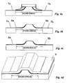
- Figs. 4a to 4d show a first alternative starting after the formation step of mask 5 in Fig. 3d.
- the thick insulator layer 3 established earlier as explained above with Fig. 3b, is not etched down to the semiconductor body 2, but to a predetermined thickness on the body. This etching results in relatively thin insulating layers 7a and 7b, as shown in Fig. 4a, extending over the whole of or part of the semiconductor body.
- Their thickness may be selected in the region of 15 to 40 nm, preferably about 25. The choice depends on the desired overall absorption of the CIG element.
- the insulator strips 6a and 6b and/or the thin outer insulator layers 7a and 7b extend preferably along the whole length and width of the semiconductor body, but may also be shorter and/or narrower than the latter if desired.
- the thin outer insulator layers 7a and 7b electrically separate the absorbing material from the semiconductor and thus avoid any undesired leak currents and/or undesired material interactions at the interface. Furthermore, they may be utilized to modify the overall absorption of the CIG element.
- Fig. 4b shows the structure after lift-off of the photoresist masks 1 and 5, as previously described for Fig. 3f.
- the next step is the deposition of the absorbing layer 8a and 8b as part of the p-metallisation.
- the result is demonstrated in Fig. 4c and was previously described for Fig. 3g.
- Fig. 4d shows the nearly complete RWG laser diode structure having the additional P-contact layer 9 deposited necessary for electrical powering of the diode.
- the CIG elements located left and right of the ridge now consist of two layers: the thin insulating layers 7a and 7b and the optically absorbing layers 8a and 8b.
- Figs. 5a to 5d show a second alternative for fabricating a CIG element with an insulation layer underneath the absorbing layer.
- the thick insulating layer is etched down to the semiconductor body 2.
- the photoresist masks are subsequently removed by lift-off to result in a structure containing the semiconductor body 2 with the ridge and the two thick insulating layers 6a and 6b to both sides of the ridge. This is shown in Fig. 5a.
- a thin insulating layer again preferably 25 nm, is deposited covering the entire semiconductor body 2, thus forming the first layer of the CIG elements 7a and 7b as shown in Fig. 5b.
- the material can now be choosen and deposited independent of the thick insulating material. Standard materials and deposition methods for this purpose are insulators such as Si 3 N 4 , TiO 2 , SiO 2 , AIN deposited by PVD, CVD or MOCVD.
- this thin insulator covers the entire surface of the semiconductor body, it also covers the contact area on top of the ridge. In this latter area, the thin insulator must be removed to provide electrical contact of the semiconductor with the p-metal. This can be done by any common method with photoresist masks and subsequent etching, preferably RIE etching. A person skilled in the art will know how to realize this. The result is shown in Fig. 5c.
- the p-metal layer 9 which also provides and functions as the absorption layers 8a and 8b of the CIG element, is deposited resulting in a structure shown in Fig. 5d.
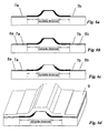
- Fig. 6a shows the structure with the thick insulating layers 6a and 6b at both sides of the ridge and the thin insulating layer 7a/b deposited across the entire semiconductor surface. This structure is generated in the same manner as described earlier for Fig. 5b.
- an absorption layer is deposited, also covering the entire body and forming the necessary absorption layers 8a and 8b for the CIG elements. This is shown in Fig. 6b.
- the two layers forming the CIG element 7a/b and 8a/b must be removed from the p-contact area. This is again done by any common masking and subsequent etching step and results in the structure shown in Fig. 6c.
- Fig. 6d finally shows the RWG structure after deposition of the p-metallisation, i.e. the p-contact layer 9.
- the advantage of the process described last is the ability to choose any stack of materials for the CIG element composition independent of p-metallisation.
- the only requirement for the absorption layer 8a/b remains now the absorption property at the lasing wavelength.
- the choice of materials was limited to materials providing good contact to the semiconductor, preferably a conductor of the type Ti, Cr, Pt.
- any material and thickness can be used as long as the material provides absorption at the lasing wavelength.
- the CIG element can be modified to any shape to cover only part of the semiconductor body.
- FIGs. 7a to 7c A fourth alternative is described in Figs. 7a to 7c.
- an absorption layer 8a, 8b is deposited over the semiconductor body 2, including both the ridge etching mask 1 and the photoresist shaping masks 5. This is shown in Fig. 7a.
- CIG elements 8a and 8b remain, extending over the semiconductor body except the ridge and its vicinity, i.e. the insulator strips 6a, 6b and 7a, 7b.
- the result, shown in Fig. 7b are two separate CIG elements 8a and 8b.
- the absorption layer may extend over only part of the semiconductor body. A person skilled in the art will know how to achieve this.
- Fig. 7c shows the structure after lifting-off the masks and depositing the usual P-contact metallisation layer 9.
- the advantage of this alternative is that material and thickness for the P-contact metallisation and the CIG element can be chosen independently.
Landscapes
- Physics & Mathematics (AREA)
- Condensed Matter Physics & Semiconductors (AREA)
- General Physics & Mathematics (AREA)
- Electromagnetism (AREA)
- Optics & Photonics (AREA)
- Geometry (AREA)
- Semiconductor Lasers (AREA)
Description
- This invention relates to semiconductor laser diodes, in particular to ridge waveguide (RWG) diodes, and a method for making such diodes. RWG laser diodes are especially used as pump lasers in fiber optic networks and similar applications since they provide the desired narrow-bandwidth optical radiation with a stable light output power in a given frequency band. Naturally, output power and stability of such laser diodes are of crucial interest. The present invention relates to an improved laser diode, the improvement in particular concerning the structure and design of the ridge waveguide; it also relates to a manufacturing process for such a laser diode.
- Coupling light of a semiconductor laser diode into an optical fiber is a central problem within the field of optical networks, in particular when high power transmission/coupling is desired. Due to increasing channel density in DWDM (Dense Wavelength Division Multiplexing) long haul networks, and the power requirements at elevated temperatures in metro networks, maximizing the laser diode's operating light output power is a primary design criterion. The useful operating power is mainly limited by a "kink" in the L-I curves, i.e. the light output over current curves, indicating a beam steering in lateral direction. The occurrence of such a kink is influenced by the real refractive index step, the gain profile as well as spatial hole burning and local heating in the laser diode. Depending on the device structure, the laser diode suffers at a certain power level from the resonance between the fundamental mode and higher order modes in lateral direction. This has been shown by J. Guthrie et al in "Beam instability in 980nm power lasers: Experiment and Analysis" in IEEE Pot. Tech. Lett. 6(12), 1994, pp. 1409-1411. Generation of higher order modes is highly undesirable since efficient laser to fiber coupling is only possible with the fundamental mode.
- Since weakly guided semiconductor devices like ridge waveguide (RWG) laser diodes are preferred for high power applications, as shown by B.E. Schmidt et al in "Pump laser diodes", Optical Filter Telecommunications IVA, Editors: Kaminov and Li, Academic Press, 2002, ISBN 0-12-395172-0, pp. 563-586, an improvement in RWG designs appears highly desirable.
- Bowler US patent 6 141 365 describes a semiconductor laser with a kink suppression layer. Reportedly, the latter limits the establishment of higher order lateral modes and thus increases the kink power of the device. Bowler also discloses disposing an optical layer along the optical axis of an RWG laser on both sides of the laser's ridge. However, shape and size of this kink suppression layer is essentially determined by the photoresist mask used to form the ridge. Bowler does not address utilizing the kink suppression layer's shape, thickness, and/or material for any particular purpose apart from general kink suppression. Also, the lasers described by Bowler have output powers of no more than 200 to 300 mW which is insufficient for many of today's technical applications.
- A similar semiconductor laser as disclosed in US patent 6 141 365 is described in US patent 6 366 595.
- Thus, it is a general object of this invention to devise a reliable design for a high power RWG laser diode which in particular provides a stable light output under all operating conditions and a sufficiently long life of such laser diodes. Hereinbelow, the term "high power" is used for an optical output power approximating 1 W. Laser diodes with 918 mW linear kink-free power have been realized with a design according to the present invention.
- It is a further primary object of this invention to provide an advantageous and economical manufacturing method for a novel high power RWG laser diode, allowing reliable mass production of such laser diodes.
- It is a more specific object of this invention to provide a RWG laser diode design optimally suited for realizing laser diodes with kink-free output powers in the 1 W region, and an increase of about 25% in median linear power (taken over about 700 devices) compared to a standard design.
- A laser diode according to the invention and its fabrication is defined in
claims 1 and 16, 18 - 22 respectively. Further embodiments of the invention are the subject-matter of dependent claims 2 - 15, 17 and 23. - The principal design idea of the invention is to develop a structure of a high power RWG laser diode which controllably introduces additional optical losses for first and higher order modes, whereas the fundamental (or 0th order) mode experiences only minor influences.
- It is known that high order lateral modes, e.g. the first order mode, exhibit a broader extension of the optical field in lateral direction than the fundamental mode. In other words, the lateral extension of the desired fundamental mode is smaller than that of the undesirable first order and higher order modes. These undesired modes can be suppressed by introducing optically absorbing regions parallel to the ridge waveguide.
- Hence, depending on the location, an absorbing layer can function as a suppression layer for the first and higher order modes, without introducing significant absorption of the fundamental mode.
- Due to the increased loss in the first order mode, resonant coupling occurs at much higher power levels and hence the linear power, i.e. the kink-free power, of the laser diode is significantly increased. Since attenuation of first and higher order modes is stronger than the same for the fundamental mode, this layer acts as a mode-discrimination element.
- The absorption layer can be made of any material in which the imaginary part of the complex index of refraction is not zero for the wavelength in question, i.e. the lasing wavelength. The element that discriminates first and higher order modes can be a single layer or contain multiple layers, where at least one layer must have the desired absorption properties. Number and location of these mode-discrimination elements (or Complex Index Guiding, CIG, elements) within the laser diode structure as well as shape and number of layers contained within the element depend on the laser design and have to be individually optimized.
- The improvement achieved by adding CIG elements to a standard RWG structure can be demonstrated. The linear power for a laser diode with CIG elements as described is significantly higher than for a similar standard laser diode. In one trial embodiment of a laser diode according to the invention, about 900 mW kink-free light output power was reached at an operating current of around 1.1 A. The median linear, i.e. kink-free, power taken over about 700 laser diodes increased by about 25% for laser diode structures containing CIG elements compared to standard diodes.
- In a first series of experiments, the photoresist etching mask already used for ridge etching was employed as mask for RIE etching the insulating layer, similar to the method described by Bowler in US patent 6 141 365, cited above. The insulating layer at both sides of the ridge was etched down to the semiconductor. Subsequently, the p-contact metallisation (Ti/Pt/Au) was deposited. The Ti layer of the metallisation functioned as the optically absorbing layer, i.e. the CIG element, in this case. Depending on the laser design, the linear power was increased anywhere from 10% to 20%. At the same time, the efficiency decreased by 10% to 20%, indicating significant absorption of the fundamental mode.
- In further experiments, the design was improved by laterally varying the distance of the CIG elements relative to ridge and herewith the extension of the modes. The purpose of this variation is to optimize absorption of higher order modes relative to the fundamental mode and thus optimize linear power and minimize efficiency losses. Furthermore, a thin insulating layer was added to the CIG element. This layer is electrically insulating and does not absorb light of the lasing wavelength. It is located between the semiconductor body and the absorption layer. The overall absorption now not only depends on the material of the absorption layer and the location of the CIG element, but also on the thickness of this insulating layer, i.e. the vertical distance of the modes from the absorption layer. Additionally, the insulator electrically separates the absorption layer, which is a conductor in the present case, from the semiconductor and thus eliminates the possibility of leaking currents.
- These variations rendered very interesting results and thus form an essential part of this invention. They will be described in detail later. In three variations, the CIG elements were located at 0, 300, and 600nm distance relative to both sides of the ridge, i.e. measured from ridge etching mask. The thin insulating layer, here case Si3N4, was part of the CIG elements for all experiments and had a thickness of about 25nm. On average, the linear power of these laser diodes increased by about 25% relative to laser diodes without CIG elements. Relative to standard laser diodes, the average efficiency was reduced by about 10% for lasers, where the CIG elements were located right next to the ridge, i.e. at 0nm from ridge etching mask. For the two designs where the CIG elements were taken further from the ridge, i.e. 300nm and 600nm relative to the ridge etching mask, the efficiency was reduced by only about 5%.
- In one embodiment, the lateral and vertical far-field showed stable single mode outputs above 900 mW and no lateral beam steering was observed in the whole power range.
- The three experimentally evaluated locations of the CIG elements show clearly that optimization reduces the detrimental effect on the fundamental mode and thus increases the efficiency and kink power even further.
- The laser diodes with the improved CIG design were tested under accelerated conditions for stability, failures and degradation. The CIG-improved lasers showed stable performance, indicating highly reliable operation. No distinctive features were observed compared to standard laser diodes. The operating conditions were 900 mA constant current at 85°C heat sink temperature, 3000 hrs.
- To summarize, the invention concerns a novel high power ridge waveguide semiconductor laser design containing one or more CIG elements (Complex Index Guiding elements). These CIG elements consist of at least one layer that absorbs light of the lasing wavelength, but may contain a plurality of absorbing and non-absorbing layers. The novel laser exhibits high stability with increased kink power. The CIG elements are preferably located to both sides of the ridge along the optical axis. Precise location and shape of the CIG element as well as number and location of layers in the CIG element depend on the laser design and are choosen to achieve maximum efficiency and/or maximum kink power.
- The novel manufacturing process according to the invention allows control of the distance relative to the extension of fundamental and first order modes and hence optimization of increased kink power vs. optical losses. Experimental results show an increased kink power of about 25% (median) and very good life-time results.
- As already addressed, the position of the absorbing layer relative to the fundamental mode is rather critical. This is due to the fact that absorption of the first order mode is desired, but absorption of the fundamental mode is undesirable since it results in reduced efficiency. The described novel manufacturing method allows control of the distance of the absorbing layer relative to the ridge by a self-aligning process. This optimizes the kink power increase by absorption of the first order mode without significantly loosing efficiency by absorption of the fundamental mode. Since the location of the CIG elements can be defined independently of the ridge and its etching mask, any epitaxial design and any ridge design can be used.
- The fabrication method according to the invention has the further advantage that it does not put limitations on the CIG elements in terms of position, thickness, material and deposition method. Also, the novel method facilitates the introduction of a thin insulating layer underneath the absorbtion layer to electrically separate the semiconductor from the metal and thus avoid leaking currents and to modify the overall absorption.
- In the following, various embodiments of the invention, including some basic considerations and both the laser structure and the manufacturing process, shall be described by reference to the drawings, in which:
- Fig. 1
- shows the influence of an absorbing layer on various modes of an RWG laser;
- Fig. 2
- shows the measured P-I curve of a standard device compared to a CIG-improved device according to the invention;
- Figs. 3a - 3g
- illustrate the preferred manufacturing process of an RWG laser diode according to the invention;
- Fig. 3h
- depicts the structure of a first example of an RWG laser diode according to the invention;
- Fig. 3i
- shows the optical energy distribution of an RWG laser diode according to Fig. 3h;
- Figs. 4a - 4c
- illustrate the first alternative manufacturing process of an RWG laser diode according to the invention; and
- Fig. 4d
- shows the design of a second example of an RWG laser diode according to the invention;
- Figs. 5a-5c
- illustrate a second alternative manufacturing process of an RWG laser diode according to the invention; and
- Fig. 5d
- shows the design of a third example of an RWG laser diode according to the invention.
- Figs. 6a-6c
- illustrate a third alternative manufacturing process of an RWG laser diode according to the invention; and
- Fig. 6d
- shows the design of a fourth example of an RWG laser diode according to the invention.
- Figs. 7a-7b
- illustrate a fourth alternative manufacturing process of an RWG laser diode according to the invention; and
- Fig. 7c
- shows the design of a fifth example of an RWG laser diode according to the invention.
- Fig. 1 is a schematic representation of the principle influence of an absorbing layer on various modes of an RWG laser diode. The upper part of Fig. 1 shows the distribution of the "gain" extending over the lateral extension "x" of an RWG laser diode without and with an absorbing layer, the latter according to the invention (dotted lines). As explained above, it is clearly visible that the addition of an absorbing layer reduces the gain in lateral regions, but not in the center region of the diode.
- The lower part of Fig. 1 now shows the calculated lateral distribution of the optical energy of the fundamental mode (dotted line) and the first order mode, again over the lateral extension "x" and the vertical extension "y". It is obvious that the first order mode shows a significantly different lateral distribution of its optical energy, in particular shows it a much higher level than the fundamental mode (dotted lines) in the laterally more distant regions and a minimum at the center region. Here, the invention sets in by providing lateral absorbing layers, appropriately positioned parallel to the waveguide, which significantly suppress the first order mode. This in turn leads to an increase in the linear power of the pump laser device since resonant coupling of the first order mode now occurs at higher power levels.
- Fig. 2 illustrates the improvement achieved by adding CIG elements according to the invention to the RWG laser diode structure. The figure shows the P-I curve, i.e. power versus injected current in arbitrary units (a.u.), for a standard diode compared to a CIG-improved diode. Indicated is the first occurring kink, i.e. instability of the optical output power of a standard diode vs. a CIG-improved diode. The first kink clearly occurs at a much lower power level for the standard diode than for the same diode comprising CIG elements. As stated before, stable output powers of more than 900 mW were achieved with the improved CIG design with good life test results. Heretofore, it was difficult or impossible to reach an output power of more than 900mW with both stability and long life of the laser diodes.
- Initially, a manufacturing method of RWG laser diodes according to the invention shall be described since many details will become clear from the preferred manufacturing process. Different stages and variations of this method are illustrated in Figs. 3a to 6c. A person skilled in the art may of course vary this process, e.g. by modifying and/or deleting certain steps and/or by adding further steps, without departing from the invention.
- Please note that the figures showing the RWG laser diode are not to scale, in particular are the thicknesses of the various layers greatly exaggerated to make them visible. Please note also that the manufacturing process is only explained with regard to the present invention and is insofar incomplete as those steps and measures known to the person skilled in the art are not mentioned or described.
- Fig. 3a starts with the ridge formation by a wet etching process. The part of a
semiconductor body 2 which is supposed to form the ridge of the final RWG laser diode is covered by aphotoresist mask 1, the ridge etching mask. GaAs or AlGaAs are the preferred materials for thebody 2. However, the process is not limited to these materials, but can be applied also to InP or any other optical semiconductor material. The etching step results in asemiconductor body 2 having the shape shown in Fig. 3a, i.e. the ridge is formed. Here, the shape results from a wet etching process, but the CIG element formation process will work as well on other ridge shapes having, e.g. straight side walls or sidewalls of other shapes. Important for the later described CIG layer self-aligned masking process is only the presence of some kind of a mesa structure. - In the next step, shown in Fig. 3b, a
thin insulator layer 3, preferably Si3N4, is deposited across the entire structure. The deposition can be achieved by a PECVD process, i.e. by Physically Enhanced Chemical Vapor Deposition. The thickness of thisinsulator layer 3 is in the region of 200 to 300 nm, preferably about 220 nm. Theinsulator layer 3 can also be made of alternative materials, such as SiO2, AIN, or TiO2, and be deposited by alternative deposition methods, such as PVD, i.e. Physical Vapor Deposition, or CVD, i.e. Chemical Vapour Deposition. - Whereas the steps themselves above are more or less state of the art, they form the basis for subsequent steps focussing on the invention.
- The steps illustrated in Figs. 3c to 3g produce the mask that defines the location of the absorbing CIG elements. It is effectively the thick Si3N4 insulator layer 3 that acts as a mask for the desired absorbing layer. This insulator layer optically separates the light generated in the waveguide from the absorbing layer. In the regions with thick Si3N4, any absorbing layer deposited on top will not (or only marginally) contribute to the absorption.
- In the step shown in Fig. 3c, a photoresist layer 4 is deposited over the
whole semiconductor body 2, includinginsulator layer 3 andmask 1. Preferably, the photoresist is spun over thesemiconductor body 2, resulting in a thicker photoresist layer near the ridge and a thinner photoresist layer in the body region. The thickness of the resulting photoresist layer 4 is preferably about 2.5 µm in the region of the ridge and about 1 µm in the body region. The thickness gradient of the photoresist layer 4 is important for the variability of the absorbing layer (or CIG element) location and shape, as will be shown later. The photoresist deposition of Fig. 3c prepares the device for the subsequent Si3N4 masking. - To provide the masking necessary for the fabrication the CIG element(s), the photoresist is etched to a desired shape, here specifically a variable width or distance, measured from the ridge center. A preferred method for this shaping step is RIE, i.e. Reactive Ion Etching. This results in the shaping masks 5 illustrated in Fig. 3d. The control of the width of this shaping mask may be facilitated by a rather directional etching process and/or the choice of an appropriate etch time. A person skilled in the art will know how to modify the etching process in order to achieve the desired result.
- More precisely, Fig. 3d shows three different masks: a narrow one, essentially of the same width as the ridge
etching photoresist mask 1; a middle one, somewhat wider than saidridge etching mask 1; and a wide one, identified by the outermost line shown in Fig. 3d. All three widths are shown to clearly demonstrate the variability of the mask. - In a subsequent step, shown in Fig. 3e, the
insulator layer 3, established earlier as described above with Fig. 3b, is etched down to thesemiconductor body 2. After this etching, theinsulator layer 3 remains only at the flanks of the ridge and underneath the photoresist mask which was established in the previous step (Fig. 3d) and forms the insulator strips 6a and 6b on both sides of the ridge. They extend preferably along the whole length of thesemiconductor body 2, but may be shorter than the latter if desired. The total width of the insulator strips 6a and 6b varies with the width of the shapingmask 5. The shape of the insulator strips also determines the effective location of the CIG element, i.e. the location where absorption of light mainly occurs. - After the etching process described in Fig. 3e, the
photoresist shaping mask 5 used for the Si3N4 or any similar etching as well as the ridgeetching photoresist mask 1 are removed, e.g. by lift-off. The result is illustrated in Fig. 3f. - As shown in Fig. 3g, a layer of optically absorbing material, resulting in an uninterupted layer covering the
whole semiconductor body 2 is deposited. This layer has two functions : - It provides the contact layer for the usual P-contact metallisation on top of the ridge.
- It provides the absorption necessary suppressing the undesired first and higher order modes of the laser by forming absorption layers (or CIG elements) 8a and 8b at both sides of the ridge. As stated earlier, the location where absorption takes place, i.e. where the CIG element is effective, is confined to those areas left and right of the ridge where the
semiconductor body 2 is not covered by the thick insulator strips 6a and 6b. If desired, the absorption layer may extend over only part of the semiconductor body's length. A person skilled in the art will know how to achieve this. - Consequently, this absorption layer must have two important material properties:
- It must be a material in which the imaginary part of the complex refractive index is non-zero for the wavelength in question, i.e. the lasing wavelength.
- For the process described, it must also be suitable as a first contact layer for the p-contact metallisation. Conductors such as Ti and Cr are suitable in this case.
- Fig. 3h shows the nearly complete RWG laser diode structure having the additional P-
contact layers 9 deposited necessary for electrical powering of the diode. - Any other steps in the manufacturing process to complete the RWG laser diode remain essentially standard and are well known to a person skilled in the art. These steps thus need not be described here.
- Fig. 3i finally shows, somewhat similar to Fig. 1, the optical power distribution of the RWG laser diode shown in Fig. 3h approximately in relative dimensions to the structure in Fig. 3h. It is clearly visible that the fundamental mode has its usual peak in the center of the laser diode, whereas the first order mode - as any higher order modes - extend further into the areas where the CIG elements are located. Thus, the first and higher modes are strongly attenuated, which is what the invention intends to achieve.
- Depending on the laser design (e.g. ridge shape, epitaxial design) the lateral extension of the modes within the laser diode varies. Accordingly, changes must be made with regard to the optimal location of the CIG elements to achieve the desired maximum absorption of first and higher order modes and minimum absorption of the fundamental mode. It is therefore important to have a process that allows variable placement and shape of the CIG elements independent of, but adapted to, the laser's ridge shape and design. The present invention provides this flexiblity and adaptibility.
- Some alternatives for the deposition and the arrangement of the absorption layer(s) or complex index guiding (CIG) element(s) will be addressed in the following.
- Figs. 4a to 4d show a first alternative starting after the formation step of
mask 5 in Fig. 3d. In this case, thethick insulator layer 3, established earlier as explained above with Fig. 3b, is not etched down to thesemiconductor body 2, but to a predetermined thickness on the body. This etching results in relatively thininsulating layers outer insulator layers outer insulator layers - Fig. 4b shows the structure after lift-off of the
photoresist masks absorbing layer - Fig. 4d shows the nearly complete RWG laser diode structure having the additional P-
contact layer 9 deposited necessary for electrical powering of the diode. The CIG elements located left and right of the ridge now consist of two layers: the thin insulatinglayers layers - Figs. 5a to 5d show a second alternative for fabricating a CIG element with an insulation layer underneath the absorbing layer. As described for the first process and shown in Figs. 3e and 3f, the thick insulating layer is etched down to the
semiconductor body 2. The photoresist masks are subsequently removed by lift-off to result in a structure containing thesemiconductor body 2 with the ridge and the two thick insulatinglayers - In a next step a thin insulating layer, again preferably 25 nm, is deposited covering the
entire semiconductor body 2, thus forming the first layer of theCIG elements - Since this thin insulator covers the entire surface of the semiconductor body, it also covers the contact area on top of the ridge. In this latter area, the thin insulator must be removed to provide electrical contact of the semiconductor with the p-metal. This can be done by any common method with photoresist masks and subsequent etching, preferably RIE etching. A person skilled in the art will know how to realize this. The result is shown in Fig. 5c.
- Finally, the p-
metal layer 9, which also provides and functions as the absorption layers 8a and 8b of the CIG element, is deposited resulting in a structure shown in Fig. 5d. - The third alternative process is similar to the previous one, but allows the utilization of different materials for the CIG element independent of the thick insulating layer(s) and the p-metal layer. Fig. 6a shows the structure with the thick insulating
layers layer 7a/b deposited across the entire semiconductor surface. This structure is generated in the same manner as described earlier for Fig. 5b. - In a next step, an absorption layer is deposited, also covering the entire body and forming the
necessary absorption layers CIG element 7a/b and 8a/b must be removed from the p-contact area. This is again done by any common masking and subsequent etching step and results in the structure shown in Fig. 6c. - Fig. 6d finally shows the RWG structure after deposition of the p-metallisation, i.e. the p-
contact layer 9. The advantage of the process described last is the ability to choose any stack of materials for the CIG element composition independent of p-metallisation. The only requirement for theabsorption layer 8a/b remains now the absorption property at the lasing wavelength. In the previously described processes, the choice of materials was limited to materials providing good contact to the semiconductor, preferably a conductor of the type Ti, Cr, Pt. For this last process however, any material and thickness can be used as long as the material provides absorption at the lasing wavelength. Additionally the CIG element can be modified to any shape to cover only part of the semiconductor body. - A fourth alternative is described in Figs. 7a to 7c. Starting from a structure as in Fig. 3e or 4a, an
absorption layer semiconductor body 2, including both theridge etching mask 1 and the photoresist shaping masks 5. This is shown in Fig. 7a. When the photoresist masks are now lifted off,CIG elements separate CIG elements - Fig. 7c shows the structure after lifting-off the masks and depositing the usual P-
contact metallisation layer 9. The advantage of this alternative is that material and thickness for the P-contact metallisation and the CIG element can be chosen independently. - Further modifications will readily occur to a person skilled in the art and the invention is therefore not limited to the specific embodiments, details, and steps shown and described herein before. Modifications may be made without departing from the scope of the general inventive concepts as defined in the appended claims.
Claims (23)
- A laser diode with a semiconductor body (2) and an active region including a ridge waveguide, said laser diode having an optically absorbing element for suppressing first and higher order modes, wherein
said absorbing element includes, or consists of one or more complex index guiding (CIG) elements with at least an absorption layer (8a, 8b) and an insulation layer, said insulation layer (3) being between said semiconductor body (2) and said absorption layer (8a, 8b),
said one or more CIG elements is/are arranged at a predetermined location on said semiconductor body (2) along and parallel to said ridge waveguide,
said location, number, and structure of said CIG elements being selected to maximize supression of unwanted higher order modes of said laser diode by said insulation layer (3) having eitherlateral sections of different thicknesses, a first section of greater thickness (6a, 6b) close to the ridge waveguide and a second section of smaller thickness (7a, 7b) distant from the ridge waveguide, ora lateral extension smaller than said absorption layer (8a, 8b). - The laser diode according to claim 1, wherein
two or more CIG elements is/are arranged symmetrically at a predetermined location on the semiconductor body. - The laser diode according to claim 1, wherein
the absorption layer (8a, 8b) further serves as a contact layer for said laser's ridge waveguide. - The laser diode according to claim 1, wherein
the CIG element or elements comprises, or consists of, a plurality or stack of insulating and absorption layers (8a, 8b). - The laser diode according to any preceding claim, wherein
at least two CIG elements are provided as layer structures preferably located on both sides of the ridge waveguide and extending along the whole length of the semiconductor body (2). - (amended) The laser diode according to any of the claims 1 to 4, wherein at least two CIG elements are provided as layer structures, one each preferably located on either side of the ridge waveguide and extending only partially along the length of the semiconductor body (2).
- The laser diode according to claim 1, wherein
the CIG element is shaped to maximize suppression of first and higher order modes while minimizing absorption of the fundamental mode. - The laser diode according to any preceding claim, wherein
the thickness of the insulation layer between the semiconductor body (2) and
the absorption layer (8a, 8b) is selected to minimize absorption of the fundamental mode while maximizing suppression of first and higher order modes. - The laser diode according to any preceding claim, wherein
the thickness of the absorption layer (8a, 8b) is selected to maximize suppression of first and higher order modes while minimizing absorption of the fundamental mode. - The laser diode according to any preceding claim, wherein
the material of the absorption layer (8a, 8b) is selected to maximize suppression of first and higher order modes while minimizing absorption of the fundamental mode. - The laser diode according to claim 4, wherein
materials and thickness for the CIG element or elements are selected to maximize suppression of first and higher order modes while minimizing absorption of the fundamental mode. - The laser diode according to any preceding claim, wherein
the absorption layer (8a, 8b) covers a part of the semiconductor body, preferably the whole surface of said body. - The laser diode according to claim 12, wherein
the absorption layer (8a, 8b) further serves as a contact layer for said laser's ridge waveguide. - The laser diode according to any preceding claim, wherein
the semiconductor body (2) is of i.e. GaAs or InP based materials and the complex index guiding element comprises a conductor or a semiconductor, i.e. Ti, Cr, Pt, Au, Si. - The laser diode according to any preceding claim, wherein
the semiconductor body is of i.e. GaAs or InP based materials and the complex index guiding element comprises a insulator, i.e. TiO2, Si3N4, AIN, SiO2. - A method for making a high power laser diode with a semiconductor body (2) and a ridge waveguide as active region, comprising the following steps(a) providing said semiconductor body with said ridge waveguide by a first photoresist mask (Fig. 3a, 1),(b) depositing an insulator (Fig. 3b, 3) over at least part of said semiconductor body including said first mask (1),(c) depositing a photoresist (Fig. 3c, 4) on said insulator,(d) removing part of said photoresist in a controlled way to provide a second photoresist mask (Fig. 3d, 5) with a predetermined size wider than said ridge waveguide,(e) removing said insulator (Fig. 3e) where it is uncovered by said second mask,(f) removing both said first and said second photoresist masks (Fig. 3f),(g) depositing an absorption layer (Fig. 3g, 8a, 8b) as part of a complex index guiding (CIG) element and as contact layer (Fig. 3h, 9).
- The method according to claim 16, wherein
step (e) is replaced by (e'):thinning the insulator (Fig. 4b) to a predetermined thickness where it is uncovered by the second mask to provide insulator areas of a first thickness (6a, 6b) under said second mask and of a second thickness (7a, 7b) outside said second mask. - The method according to claim 16 or 17, wherein
step (g) is replaced by steps (g') and (g"):(g') depositing an absorption layer (Fig. 3g, 8a, 8b) as part of a complex index guiding (CIG) element and(g") depositing a contact layer (Fig. 3h, 9). - A method for making a high power laser diode with a semiconductor body (2) and a ridge waveguide as active region, comprising the following steps(a) making said ridge waveguide on said semiconductor body by means of a first photoresist mask (Fig. 3a, 1),(b) depositing an insulator (Fig. 3b, 3) over at least part of said semiconductor body (2) including said first mask (1),(c) depositing a photoresist (Fig. 3c, 4) on said insulator (3),(d) removing part of said photoresist (Fig. 3d) in a controlled way to provide a second photoresist mask (5) with a predetermined size wider than said ridge waveguide,(e) removing said insulator (Fig. 3e) where it is uncovered by said second mask (5),(f) removing both said first and said second photoresist masks (1, 5) including a part of said insulator (3),(g) depositing a thin insulator (Fig. 5b, 7a, 7b) over at least part of said semiconductor body including said ridge waveguide,(h) removing said thin insulator in the contact region of said ridge waveguide (Fig. 5c),(i) depositing an absorption layer (Fig. 5d, 8a, 8b) as part of a complex index guiding (CIG) element and as contact layer (Fig. 5d, 9).
- The method according to claim 19, wherein
step (i) is replaced by steps (i') and (i"):(i') depositing an absorption layer (Fig. 3g, 8a, 8b) as part of a complex index guiding (CIG) element and(i") depositing a contact layer (Fig. 3h, 9). - The method according to claim 20, wherein
step (g) is replaced by (g'):depositing a thin insulator and an absorption layer over at least part of said semiconductor body including the ridge,and step (h) is replaced by (h'):removing the thin insulator and the absorption layer in the contact region of said ridge, leaving the thin insulator and the absorption layer (8a, 8b) as CIG elements to both sides of the ridge. - The method according to claim 21, wherein
step (g') is replaced by (g"):depositing a stack of insulators and absorption layers over at least part of said semiconductor body including the ridge,and step (h') is replaced by (h"):removing the stack in the contact region of said ridge, leaving the stack as CIG elements to both sides of the ridge. - The method according to any of the claims 16 to 22, wherein
the deposited insulator is Si3N4, SiO2, TiO2, and/or AIN and the conductive material for the absorption and/or contact layers is Au, Cr, Pt and/or Ti.
Applications Claiming Priority (3)
| Application Number | Priority Date | Filing Date | Title |
|---|---|---|---|
| US245199 | 1981-03-18 | ||
| US10/245,199 US6862300B1 (en) | 2002-09-17 | 2002-09-17 | High power semiconductor laser diode and method for making such a diode |
| PCT/IB2003/003929 WO2004027951A1 (en) | 2002-09-17 | 2003-08-22 | High power semiconductor laser diode and method for making such a diode |
Publications (2)
| Publication Number | Publication Date |
|---|---|
| EP1547216A1 EP1547216A1 (en) | 2005-06-29 |
| EP1547216B1 true EP1547216B1 (en) | 2007-02-14 |
Family
ID=32028932
Family Applications (1)
| Application Number | Title | Priority Date | Filing Date |
|---|---|---|---|
| EP03797442A Expired - Lifetime EP1547216B1 (en) | 2002-09-17 | 2003-08-22 | High power semiconductor laser diode and method for making such a diode |
Country Status (5)
| Country | Link |
|---|---|
| US (3) | US6862300B1 (en) |
| EP (1) | EP1547216B1 (en) |
| AU (1) | AU2003263419A1 (en) |
| DE (1) | DE60311844T2 (en) |
| WO (1) | WO2004027951A1 (en) |
Families Citing this family (12)
| Publication number | Priority date | Publication date | Assignee | Title |
|---|---|---|---|---|
| DE102006046297A1 (en) * | 2006-09-29 | 2008-04-03 | Osram Opto Semiconductors Gmbh | Semiconductor laser |
| US8073031B2 (en) * | 2008-03-03 | 2011-12-06 | Sharp Kabushiki Kaisha | Laser diode with improved heat dissipation |
| US20100248715A1 (en) * | 2009-03-31 | 2010-09-30 | Soren Lundsgaard | Systems and method for optimizing wireless local area network channel scanning |
| US8718432B1 (en) * | 2011-04-21 | 2014-05-06 | Octrolix Bv | Method for forming a spotsize converter |
| US9268089B2 (en) * | 2011-04-21 | 2016-02-23 | Octrolix Bv | Layer having a non-linear taper and method of fabrication |
| DE102011075502A1 (en) | 2011-05-09 | 2012-11-15 | Forschungsverbund Berlin E.V. | Wide-band diode laser with high efficiency and low far-field divergence |
| US9166369B2 (en) | 2013-04-09 | 2015-10-20 | Nlight Photonics Corporation | Flared laser oscillator waveguide |
| US9214786B2 (en) | 2013-04-09 | 2015-12-15 | Nlight Photonics Corporation | Diode laser packages with flared laser oscillator waveguides |
| US10186836B2 (en) | 2014-10-10 | 2019-01-22 | Nlight, Inc. | Multiple flared laser oscillator waveguide |
| WO2016197137A1 (en) | 2015-06-04 | 2016-12-08 | Nlight, Inc. | Angled dbr-grating laser/amplifier with one or more mode-hopping regions |
| CN110114945B (en) * | 2016-10-28 | 2023-06-06 | 恩耐公司 | Methods, systems and devices for higher order mode suppression |
| US11031753B1 (en) * | 2017-11-13 | 2021-06-08 | The Government Of The United States Of America As Represented By The Secretary Of The Air Force | Extracting the fundamental mode in broad area quantum cascade lasers |
Family Cites Families (10)
| Publication number | Priority date | Publication date | Assignee | Title |
|---|---|---|---|---|
| US4227975A (en) * | 1979-01-29 | 1980-10-14 | Bell Telephone Laboratories, Incorporated | Selective plasma etching of dielectric masks in the presence of native oxides of group III-V compound semiconductors |
| JPS5726488A (en) | 1980-07-23 | 1982-02-12 | Fujitsu Ltd | Semiconductor light emitting device |
| JPS6261385A (en) | 1985-09-11 | 1987-03-18 | Sharp Corp | Semiconductor laser element |
| JPS62270170A (en) | 1986-05-20 | 1987-11-24 | 住友ベークライト株式会社 | Respiration tuning type oxygen feeder |
| NL8603009A (en) * | 1986-11-27 | 1988-06-16 | Philips Nv | SEMICONDUCTOR LASER AND METHOD OF MANUFACTURE THEREOF. |
| JPH0334595A (en) * | 1989-06-30 | 1991-02-14 | Matsushita Electric Ind Co Ltd | Semiconductor laser and manufacture thereof |
| JPH0521902A (en) | 1991-07-11 | 1993-01-29 | Mitsubishi Electric Corp | Semiconductor laser device |
| JP3649207B2 (en) | 1995-09-20 | 2005-05-18 | 三菱マテリアル株式会社 | Method for producing single crystal lithium tetraborate |
| US6141365A (en) * | 1997-12-31 | 2000-10-31 | Lasertron | Semiconductor laser with kink suppression layer |
| JP3849758B2 (en) * | 2001-04-12 | 2006-11-22 | ソニー株式会社 | Semiconductor laser element |
-
2002
- 2002-09-17 US US10/245,199 patent/US6862300B1/en not_active Expired - Lifetime
-
2003
- 2003-08-22 WO PCT/IB2003/003929 patent/WO2004027951A1/en not_active Ceased
- 2003-08-22 AU AU2003263419A patent/AU2003263419A1/en not_active Abandoned
- 2003-08-22 EP EP03797442A patent/EP1547216B1/en not_active Expired - Lifetime
- 2003-08-22 DE DE60311844T patent/DE60311844T2/en not_active Expired - Fee Related
-
2005
- 2005-01-21 US US11/040,246 patent/US20050201438A1/en not_active Abandoned
-
2008
- 2008-01-10 US US11/972,156 patent/US7623555B2/en not_active Expired - Lifetime
Also Published As
| Publication number | Publication date |
|---|---|
| EP1547216A1 (en) | 2005-06-29 |
| DE60311844T2 (en) | 2007-12-13 |
| WO2004027951A1 (en) | 2004-04-01 |
| DE60311844D1 (en) | 2007-03-29 |
| AU2003263419A1 (en) | 2004-04-08 |
| US7623555B2 (en) | 2009-11-24 |
| US20080123697A1 (en) | 2008-05-29 |
| US20050201438A1 (en) | 2005-09-15 |
| US6862300B1 (en) | 2005-03-01 |
Similar Documents
| Publication | Publication Date | Title |
|---|---|---|
| US7623555B2 (en) | High power semiconductor laser diode | |
| US5317587A (en) | VCSEL with separate control of current distribution and optical mode | |
| KR101532982B1 (en) | Laser light source | |
| JP6490705B2 (en) | Semiconductor optical integrated device and manufacturing method thereof | |
| US6852558B2 (en) | Methods for forming index guided vertical cavity surface emitting lasers | |
| US8319229B2 (en) | Optical semiconductor device and method for manufacturing the same | |
| US6366595B1 (en) | Semiconductor laser with kink suppression layer | |
| US20110091147A1 (en) | Integrated semiconductor optical device | |
| CN101390263B (en) | semiconductor laser device | |
| CN116488001B (en) | Double-end-face tunable laser and preparation method thereof | |
| JP2012089622A (en) | Semiconductor laser element | |
| CN111969415B (en) | Wide-spectrum multi-wavelength Fabry-Perot laser | |
| EP0527615B1 (en) | Method of making tunable semiconductor laser | |
| US20110091151A1 (en) | Integrated semiconductor optical device | |
| KR20150139694A (en) | Distributed bragg reflector ridge laser diode and fabricating method thereof | |
| KR100413527B1 (en) | Method for fabricating monolithic integrated semiconductor photonic devices | |
| KR20060038057A (en) | Semiconductor laser device and its manufacturing method | |
| WO2008114896A1 (en) | High power single mode optical devices with s-bending ridge waveguide and fabrication method thereof | |
| EP1504506A2 (en) | Semiconductor laser | |
| US6316280B1 (en) | Method of manufacturing semiconductor devices separated from a wafer | |
| JP2021153125A (en) | Quantum cascade laser | |
| US12068576B2 (en) | Optical waveguide device and laser apparatus including the same | |
| JP2002057409A (en) | Semiconductor laser and method of manufacturing the same | |
| WO2002063731A2 (en) | Sampled grating distributed reflector laser | |
| JP3788699B2 (en) | Integrated optical circuit element and manufacturing method thereof |
Legal Events
| Date | Code | Title | Description |
|---|---|---|---|
| PUAI | Public reference made under article 153(3) epc to a published international application that has entered the european phase |
Free format text: ORIGINAL CODE: 0009012 |
|
| 17P | Request for examination filed |
Effective date: 20050418 |
|
| AK | Designated contracting states |
Kind code of ref document: A1 Designated state(s): AT BE BG CH CY CZ DE DK EE ES FI FR GB GR HU IE IT LI LU MC NL PT RO SE SI SK TR |
|
| AX | Request for extension of the european patent |
Extension state: AL LT LV MK |
|
| DAX | Request for extension of the european patent (deleted) | ||
| RBV | Designated contracting states (corrected) |
Designated state(s): DE FR GB |
|
| RAP1 | Party data changed (applicant data changed or rights of an application transferred) |
Owner name: BOOKHAM TECHNOLOGY PLC |
|
| GRAP | Despatch of communication of intention to grant a patent |
Free format text: ORIGINAL CODE: EPIDOSNIGR1 |
|
| GRAS | Grant fee paid |
Free format text: ORIGINAL CODE: EPIDOSNIGR3 |
|
| GRAA | (expected) grant |
Free format text: ORIGINAL CODE: 0009210 |
|
| AK | Designated contracting states |
Kind code of ref document: B1 Designated state(s): DE FR GB |
|
| REG | Reference to a national code |
Ref country code: GB Ref legal event code: FG4D |
|
| REF | Corresponds to: |
Ref document number: 60311844 Country of ref document: DE Date of ref document: 20070329 Kind code of ref document: P |
|
| EN | Fr: translation not filed | ||
| PLBE | No opposition filed within time limit |
Free format text: ORIGINAL CODE: 0009261 |
|
| STAA | Information on the status of an ep patent application or granted ep patent |
Free format text: STATUS: NO OPPOSITION FILED WITHIN TIME LIMIT |
|
| 26N | No opposition filed |
Effective date: 20071115 |
|
| GBPC | Gb: european patent ceased through non-payment of renewal fee |
Effective date: 20070822 |
|
| PG25 | Lapsed in a contracting state [announced via postgrant information from national office to epo] |
Ref country code: FR Free format text: LAPSE BECAUSE OF FAILURE TO SUBMIT A TRANSLATION OF THE DESCRIPTION OR TO PAY THE FEE WITHIN THE PRESCRIBED TIME-LIMIT Effective date: 20071005 |
|
| PG25 | Lapsed in a contracting state [announced via postgrant information from national office to epo] |
Ref country code: DE Free format text: LAPSE BECAUSE OF NON-PAYMENT OF DUE FEES Effective date: 20080301 |
|
| PG25 | Lapsed in a contracting state [announced via postgrant information from national office to epo] |
Ref country code: FR Free format text: LAPSE BECAUSE OF FAILURE TO SUBMIT A TRANSLATION OF THE DESCRIPTION OR TO PAY THE FEE WITHIN THE PRESCRIBED TIME-LIMIT Effective date: 20070214 Ref country code: GB Free format text: LAPSE BECAUSE OF NON-PAYMENT OF DUE FEES Effective date: 20070822 |