EP1547182B1 - Thermal management system - Google Patents
Thermal management system Download PDFInfo
- Publication number
- EP1547182B1 EP1547182B1 EP03750205A EP03750205A EP1547182B1 EP 1547182 B1 EP1547182 B1 EP 1547182B1 EP 03750205 A EP03750205 A EP 03750205A EP 03750205 A EP03750205 A EP 03750205A EP 1547182 B1 EP1547182 B1 EP 1547182B1
- Authority
- EP
- European Patent Office
- Prior art keywords
- heat transfer
- heat
- transfer circuit
- temperature
- thermal management
- Prior art date
- Legal status (The legal status is an assumption and is not a legal conclusion. Google has not performed a legal analysis and makes no representation as to the accuracy of the status listed.)
- Expired - Lifetime
Links
Images

Classifications
-
- Y—GENERAL TAGGING OF NEW TECHNOLOGICAL DEVELOPMENTS; GENERAL TAGGING OF CROSS-SECTIONAL TECHNOLOGIES SPANNING OVER SEVERAL SECTIONS OF THE IPC; TECHNICAL SUBJECTS COVERED BY FORMER USPC CROSS-REFERENCE ART COLLECTIONS [XRACs] AND DIGESTS
- Y02—TECHNOLOGIES OR APPLICATIONS FOR MITIGATION OR ADAPTATION AGAINST CLIMATE CHANGE
- Y02E—REDUCTION OF GREENHOUSE GAS [GHG] EMISSIONS, RELATED TO ENERGY GENERATION, TRANSMISSION OR DISTRIBUTION
- Y02E60/00—Enabling technologies; Technologies with a potential or indirect contribution to GHG emissions mitigation
- Y02E60/30—Hydrogen technology
- Y02E60/50—Fuel cells
Definitions
- This invention relates to systems for modulating temperature of at least two heat generating components having different operating temperatures.
- heat-generating components which operate at different temperatures.
- Exemplary of this type of system are fuel cell systems which, whether stationary or vehicular, contain a number of heat-generating components requiring temperature modulation.
- Some heat-generating components of a typical fuel cell system include the fuel cell, the fuel generation system, auxiliary fuel cell temperature conditioners, and the traction motor in vehicle applications.
- Types of fuel generation systems include sodium borohydride systems, electrolyzers and fuel reformer systems.
- Auxiliary fuel cell temperature conditioners include humidity and temperature controls for, the anode and cathode streams entering the fuel cell stack, electronics or power electronics modules, condensers, charge air coolers for cooling hot air, fuel storage systems and battery conditioners.
- each circuit has its own pumping means and heat exchange means for regulating the coolant temperature, and may have a heat transfer fluid which differs from that of the other heat transfer circuits.
- An example of such a fuel cell system is described in U.S. Patent No. 5,537,956 (Rennfeld et al. ), which relates to an arrangement for cooling vehicle components by use of at least two separate cooling circuits.
- each circuit has its own pump and radiator/fan, with the first circuit including the fuel cell unit, and the second circuit including the electric drive motor and power controller.
- the two circuits are in heat exchange communication, however there is no flow communication between the two circuits.
- U.S. Patent No. 6,370,903 (Wlech ) describes a heat pump type air conditioning and heating system for use in fuel cell-powered vehicles.
- the systems described by Wlech have two separate coolant circuits and a refrigeration circuit.
- the coolant circuits operate on separate pumps and are cooled by separate radiators, and may preferably be in heat exchange communication. However, there is no flow communication between the various heating and/or cooling circuits.
- U.S. Patent No. 6,630,835 to Skala describes a fuel cell powered electric vehicle having high and low temperature heat transfer circuits.
- the high temperature heat transfer circuit includes a heat generating fuel processor, an endothermic device, and a first circulating pump.
- the low temperature heat transfer circuit includes the fuel cell, traction motor, power electronics, radiator, and a second pump. The same heat transfer fluid is used in both the high and low temperature circuits. There is some flow communication between the two circuits through a pair of conduits, with the flow through each conduit being controlled by a valve.
- JP 200075389A of Equos Research Co Ltd discloses a fuel cell which can alternatively be used to heat or cool air using one of a pair of heat transfer circuits.
- the present invention provides a thermal management system for modulating temperature of a first heat-generating component operating at a first temperature and a second heat-generating component operating at a second temperature, the first and second temperatures being different, the system comprising: (a) a first heat transfer circuit for circulating a heat transfer medium in heat exchange relation with the first heat-generating component, the first heat transfer circuit including a first heat exchanger for modulating temperature of the heat transfer medium circulating in the first heat transfer circuit; (b) a second heat transfer circuit for circulating the heat transfer medium in heat exchange relation with the second heat-generating component, the second heat transfer circuit including a second heat exchanger for modulating temperature of the heat transfer medium circulating in the second heat transfer circuit, the first and second heat transfer circuits being in flow communication with one another; (c) a circulation pump for circulating the heat transfer medium through both the first and second heat transfer circuits; wherein one of the first heat transfer circuit and the second heat transfer circuit forms a continuous loop, and the other of the first heat transfer circuit and the second heat transfer circuit having
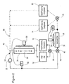
- Figure 1 illustrates a first preferred thermal management system 10 for modulating temperature of a number of components of a fuel cell power plant. It will be appreciated that the drawings do not illustrate all components of the fuel cell power plant, but only include those components which are necessary for an understanding of the present invention.
- the components of the fuel cell power plant illustrated in Figure 1 are the fuel cell 12 and a pair of components 14 and 16, all of which are exothermic under most operating conditions.
- Components 14 and 16, generally referred to herein as "heat-producing components”, are either fuel generation modules or auxiliary fuel cell temperature conditioners, as defined above.
- the specific identities of components 14 and 16 is not necessary to an understanding of the present invention, although in the specific examples described below, components 14 and 16 are auxiliary fuel cell temperature conditioners. While component 12 is referred to herein as a "fuel cell”, it will be appreciated that this component could instead comprise a fuel cell heat exchanger.
- Thermal management system 10 comprises two interconnected heat transfer circuits, a first heat transfer circuit 18 for circulating a liquid heat transfer medium in heat exchange relation with the fuel cell 12, and a second heat transfer circuit 20 for circulating the same liquid heat transfer medium in heat exchange relation with one or both of the heat-producing components 14 and 16.
- second heat transfer circuit 20 may include only one heat-producing component or may also include heat-producing components in addition to components.
- first heat transfer circuit 18 could include one or more heat-producing components in addition to fuel cell 12 which, as mentioned above, may comprise a fuel cell heat exchanger.
- the first heat transfer circuit 18 also includes a circulation pump 22, which may preferably be a single speed, multi-speed or variable speed pump, for circulating the heat transfer medium through both the first and second heat transfer circuits. More preferably, the pump 22 is a multi-speed or variable speed pump and, in the preferred embodiment shown in Figure 1 , pump 22 is located in the first heat transfer circuit 18. However, it will be appreciated that pump 22 could preferably be located in the second heat transfer circuit 20.
- a circulation pump 22 which may preferably be a single speed, multi-speed or variable speed pump, for circulating the heat transfer medium through both the first and second heat transfer circuits. More preferably, the pump 22 is a multi-speed or variable speed pump and, in the preferred embodiment shown in Figure 1 , pump 22 is located in the first heat transfer circuit 18. However, it will be appreciated that pump 22 could preferably be located in the second heat transfer circuit 20.
- a first heat exchanger 24 and a second heat exchanger 26 are provided in the first heat transfer circuit 18 and second heat transfer circuit 20, respectively.
- the heat exchangers 24, 26 are preferably provided with means for accurately controlling the temperature of the heat transfer medium.
- heat exchangers 24, 26 may preferably comprise liquid-to-liquid heat exchangers in combination with a controlled bypass as a means for controlling the temperature of the heat transfer medium.
- the use of such a system is particularly preferred in applications where it is desirable to recapture some of the heat generated by the fuel cell to an auxiliary fluid medium.
- heat exchangers 24, 26 could preferably comprise liquid-to-liquid heat exchangers which are not provided with a controlled bypass. Rather, the flow of the auxiliary fluid medium could be varied to provide temperature control in the heat transfer medium. The use of these types of systems permit the fuel cell to be brought to its operating temperature relatively quickly.
- the first heat exchanger 24 comprises a radiator 28 having a thermostatically controlled fan 30 as a means to control the temperature of the heat transfer medium, with the operation of fan 30 being controlled by a temperature controller 32.
- the second heat exchanger 26 comprises a radiator 34, a thermostatically controlled fan 36 and a temperature controller 38.
- the inventors have found that the use of radiator/fan units provides rapid temperature control.
- circulation pump 22 is a variable speed pump, it may also be used as a means for controlling the temperature of the heat transfer medium, and more preferably to control the fuel cell temperature or the temperature differential across the stack.
- the conduits comprising the first heat transfer circuit 18 are shown in solid lines, whereas the conduits comprising the second heat transfer circuit 20 are shown in dashed lines. It can be seen that the first heat transfer circuit 18 forms a continuous loop, with heat being added to the heat transfer medium by fuel cell 12 and being removed from the heat transfer medium by heat exchanger 24.
- the second heat transfer circuit 20 does not form a closed loop, and has a first end 40 and a second end 42 at which the second heat transfer circuit 20 is in flow communication with the first heat transfer circuit 18.
- either one of the first heat transfer circuit 18 or the second heat transfer circuit 20 may be a continuous loop, so long as the thermal management system 10 forms a plurality of interdependent heat transfer circuits which are controllable by a single circulation pump.
- the heat transfer circuits 18 and 20 are interdependent in that the second heat transfer circuit 20 is an open circuit which cannot be operated independently of the first heat transfer circuit 18.
- the first heat transfer circuit 18 comprises a high temperature circuit in which the heat transfer medium circulating in the first heat transfer circuit 18 is at an equal or higher temperature than the heat transfer medium circulating in the second heat transfer circuit 20.
- the temperature of the heat transfer medium circulating in heat transfer circuits 18 and 20 is not particularly limited, and may preferably be within the range of from about 40°C to about 200°C.
- the discussion of preferred embodiments refers to thermal management systems in which the temperature of the heat transfer medium is generally within the temperature range of from about 60°C to about 80°C.
- the thermal management systems according to the present invention are not limited to operation within this narrow temperature range.
- the first heat exchanger 24 controls the temperature of the heat transfer medium in the first heat transfer circuit 18 such that the temperature of heat transfer medium is about 70°C when it comes into heat exchange contact with fuel cell 12
- the second heat exchanger 26 controls the temperature in the second heat transfer circuit 20 such that the temperature of the heat transfer medium is about 60°C when it comes into heat exchange contact with the heat-producing component 14.
- the temperature of the heat transfer medium immediately downstream of the fuel cell 12 is about 80°C
- the temperature of the heat transfer medium immediately downstream of component 14 is about 65°C.
- the high and low temperature streams mix at point 42, effectively lowering the temperature of the heat transfer medium in the first heat transfer circuit 18 and reducing the required size of the first heat exchanger 24.
- the first and second heat transfer circuits 18 and 20 are balanced such that the first and second heat exchangers 24 and 26 are of similar size and heat exchange capacity.
- heat transfer medium flows from the first end 40 of second heat transfer circuit 20 to the second end, passing through second heat exchanger 26 and through one or both of the heat-producing components 14 and 16.
- the means illustrated in Figure 1 for directing flow to components 14 and 16 comprises valve 44, which may preferably comprise an active control valve or a multi-position diverter valve. However, it will be appreciated that other means for directing flow to modules 14 and 16 may be preferred, depending on the system requirements. Such alternate means include throttle valves and passive orifice plates. It may also be possible to control the flow of heat transfer medium through by strategic placement of the fuel cell components within the system.
- a controlled portion of the heat transfer medium circulating in the first heat transfer circuit 18 enters the first end 40 of the second heat transfer circuit 20.
- the flow of heat transfer medium entering second heat transfer circuit 20 may preferably be controlled by a valve and/or calibrated orifices, more preferably an active control valve, multi-position diverter valve, throttle valve or a passive orifice plate.
- the flow of heat transfer medium entering the first end 40 of the second heat transfer circuit 20 is controlled by a multi-position, three-way valve 46. It will also be appreciated that all the heat transfer medium flowing through the second heat transfer circuit 20 will flow through the second end 42 of the second heat transfer circuit 20 and into the first heat transfer circuit 18.
- first heat transfer circuit 18 a portion of the flow through first heat transfer circuit 18 is diverted into the first end 40 of second heat transfer circuit 20, and re-enters the first heat transfer circuit 18 through the second end 42 of the second heat transfer circuit 20.
- the heat transfer medium entering the first end 40 of second heat transfer circuit 20 is initially at a temperature of about 70 °C, and is cooled to about 60°C before passing through heat-producing components 14 and/or 16.
- the heat transfer medium exiting components 14 and 16 and flowing to the second end 42 of the second heat transfer circuit 20 is at a temperature of about 65°C.
- This heat transfer medium at about 65°C mixes with the heat transfer medium exiting fuel cell 12 at about 80°C, with the temperature of the heat transfer medium after mixing being about 70 to 75°C.
- This heat transfer medium is then cooled to about 70°C by the first heat exchanger 24.
- the amount of heat removed by heat exchangers 24 and 26 is thermostatically controlled by temperature controllers 32 and 38, which are positioned immediately upstream of the heat-generating components 12,14 and 16.
- temperature controllers 32 and 38 which are positioned immediately upstream of the heat-generating components 12,14 and 16.
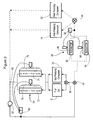
- a second preferred thermal management system 50 is illustrated in Figure 2 .
- the thermal management system 50 includes a fuel cell 12 and heat-producing components 14 and 16.
- the second preferred thermal management system 50 also modulates temperature of an additional heat-producing component 52 which may comprise either an auxiliary fuel cell temperature conditioner or a fuel generation system.
- component 52 is an auxiliary fuel cell temperature conditioner.
- the thermal management system 50 comprises a first heat transfer circuit 54 having a first heat exchanger 24 for modulating temperature of the fuel cell 12 and the heat-producing component 16, and also includes a second heat transfer circuit 58 having a second heat exchanger 26 for modulating the temperature of the heat-producing components 14 and 52.
- the conduits making up the first heat transfer circuit 54 are shown in solid lines, and those comprising the second heat transfer circuit 58 are shown in dashed lines.
- the first heat exchanger 24 comprises a radiator 28, a thermostatically controlled fan 30 and a temperature controller 32, while the second heat exchanger 26 comprises a radiator 34, a thermostatically controlled fan 36 and a temperature controller 38.
- a single pump 22 is provided to circulate the heat transfer medium through thermal management system 50.
- the first heat transfer circuit 54 forms a continuous loop while the second heat transfer circuit 58 has a first end 40 through which it receives heat transfer medium from the first circuit 54, and a second end 42 at which the heat transfer medium circulating through the second heat transfer circuit 58 is mixed with heat transfer medium flowing through the first heat transfer circuit 54.
- thermal management system 50 One difference between thermal management system 50 and thermal management system 10 is in the arrangement of the heat-generating components.
- the second heat transfer circuit 58 removes heat from components 14 and 52, with flow to components 14 and 52 being controlled by a valve or calibrated orifices 44.
- the first heat transfer circuit 54 includes the fuel cell 12 and the heat-producing component 16, with flow to these components being controlled by a valve and/or calibrated orifices 60.
- the first heat transfer circuit 54 of system 50 is the high temperature circuit, with the heat transfer medium entering the fuel cell 12 and/or component 16 being at about 70°C, and the temperature of the heat transfer medium exiting fuel cell being about 80°C.
- the second heat transfer circuit 58 which is the low temperature circuit, the temperature of heat transfer medium entering component 14 or component 52 is about 60°C, and the temperature of the heat transfer medium exiting the component 14 is about 65°C.
- thermal management system 50 Another difference between thermal management system 50 and thermal management system 10 is that the heat exchanger 24 of the second heat transfer circuit 58 is positioned downstream of the fuel cell 12 and component 16 and upstream of the point 42 at which mixing of the heat transfer medium in the first and second circuits 54, 58 takes place. Nevertheless, accurate temperature control in this embodiment is possible due to the fact that the temperature controller 32 is positioned downstream of the mixing point 42 and immediately upstream of the fuel cell 12 and component 16.
- FIG. 3 illustrates a third preferred thermal management system 70 according to the present invention.
- Thermal management system 70 can be regarded as a variant of the second preferred thermal management system 50 in which each of the heat exchangers comprises a plurality of radiators arranged in parallel to one another.
- the first heat exchanger 24 comprises a pair of radiators 72 and 74 provided with thermostatically controlled fans 76 and 78, respectively. The operation of fans 76 and 78 is controlled by temperature controller 32.
- the radiators 72, 74 each have lower heat exchange capacity than the larger radiators 28 used in the first and second preferred embodiments of the invention.
- the inventors have found that the replacement of one large radiator 24 by a pair of smaller radiators 72, 74 arranged in parallel greatly reduces the pumping requirements thereby enhancing the efficiency of the thermal management system.
- the second heat exchanger 26 of the third preferred system 70 preferably comprises a pair of radiators 82, 84 arranged in parallel, the radiators 82, 84 being provided with thermostatically controlled fans 86 and 88, respectively.
- the temperature controller 38 controls the operation of both fans 86 and 88.
Landscapes
- Fuel Cell (AREA)
Description
- This invention relates to systems for modulating temperature of at least two heat generating components having different operating temperatures.
- There are a number of known systems containing heat-generating components which operate at different temperatures. Exemplary of this type of system are fuel cell systems which, whether stationary or vehicular, contain a number of heat-generating components requiring temperature modulation. Some heat-generating components of a typical fuel cell system include the fuel cell, the fuel generation system, auxiliary fuel cell temperature conditioners, and the traction motor in vehicle applications. Types of fuel generation systems include sodium borohydride systems, electrolyzers and fuel reformer systems. Auxiliary fuel cell temperature conditioners include humidity and temperature controls for, the anode and cathode streams entering the fuel cell stack, electronics or power electronics modules, condensers, charge air coolers for cooling hot air, fuel storage systems and battery conditioners. Some of these components have different operating temperatures and therefore have different temperature modulation requirements.
- In orderto meet these different requirements, fuel cell systems have typically been provided with two or more independent heat transfer circuits. Each circuit has its own pumping means and heat exchange means for regulating the coolant temperature, and may have a heat transfer fluid which differs from that of the other heat transfer circuits. An example of such a fuel cell system is described in
U.S. Patent No. 5,537,956 (Rennfeld et al. ), which relates to an arrangement for cooling vehicle components by use of at least two separate cooling circuits. In the Rennfeld et al. system, each circuit has its own pump and radiator/fan, with the first circuit including the fuel cell unit, and the second circuit including the electric drive motor and power controller. The two circuits are in heat exchange communication, however there is no flow communication between the two circuits. -
U.S. Patent No. 6,370,903 (Wlech ) describes a heat pump type air conditioning and heating system for use in fuel cell-powered vehicles. The systems described by Wlech have two separate coolant circuits and a refrigeration circuit. The coolant circuits operate on separate pumps and are cooled by separate radiators, and may preferably be in heat exchange communication. However, there is no flow communication between the various heating and/or cooling circuits. -
U.S. Patent No. 6,630,835 to Skala describes a fuel cell powered electric vehicle having high and low temperature heat transfer circuits. The high temperature heat transfer circuit includes a heat generating fuel processor, an endothermic device, and a first circulating pump. The low temperature heat transfer circuit includes the fuel cell, traction motor, power electronics, radiator, and a second pump. The same heat transfer fluid is used in both the high and low temperature circuits. There is some flow communication between the two circuits through a pair of conduits, with the flow through each conduit being controlled by a valve. -
JP 200075389A - It will be appreciated that the provision of multiple heat transfer circuits having separate plumbing, pumps and temperature modulation means greatly increases the cost, complexity and weight of a fuel cell power plant or other operating system. Thus, there is an unsatisfied need for simpler, more efficient thermal management systems.
- In one aspect, the present invention provides a thermal management system for modulating temperature of a first heat-generating component operating at a first temperature and a second heat-generating component operating at a second temperature, the first and second temperatures being different, the system comprising: (a) a first heat transfer circuit for circulating a heat transfer medium in heat exchange relation with the first heat-generating component, the first heat transfer circuit including a first heat exchanger for modulating temperature of the heat transfer medium circulating in the first heat transfer circuit; (b) a second heat transfer circuit for circulating the heat transfer medium in heat exchange relation with the second heat-generating component, the second heat transfer circuit including a second heat exchanger for modulating temperature of the heat transfer medium circulating in the second heat transfer circuit, the first and second heat transfer circuits being in flow communication with one another; (c) a circulation pump for circulating the heat transfer medium through both the first and second heat transfer circuits; wherein one of the first heat transfer circuit and the second heat transfer circuit forms a continuous loop, and the other of the first heat transfer circuit and the second heat transfer circuit having a first end and a second end at which the circuits are in flow communication.
- Preferred embodiments of the invention will now be described, by way of example only, with reference to the accompanying drawings, in which:
-
Figure 1 is a schematic view of a first preferred thermal management system according to the invention; -
Figure 2 is a schematic view of a second preferred thermal management system according to the present invention; and -
Figure 3 is a schematic view of a third preferred thermal management system according to the present invention. - Preferred thermal management systems according to the present invention are now described below with reference to the drawings, in which like reference numerals are used to refer to similar parts of the various embodiments of the system. Although the preferred embodiments are described in connection with fuel cell systems, it will be appreciated that the present invention can be adapted to other applications, for example for thermal management of hybrid vehicle operating systems, internal combustion engines or electronics.
-
Figure 1 illustrates a first preferred thermal management system 10 for modulating temperature of a number of components of a fuel cell power plant. It will be appreciated that the drawings do not illustrate all components of the fuel cell power plant, but only include those components which are necessary for an understanding of the present invention. The components of the fuel cell power plant illustrated inFigure 1 are thefuel cell 12 and a pair ofcomponents Components components components component 12 is referred to herein as a "fuel cell", it will be appreciated that this component could instead comprise a fuel cell heat exchanger. - Thermal management system 10 comprises two interconnected heat transfer circuits, a first
heat transfer circuit 18 for circulating a liquid heat transfer medium in heat exchange relation with thefuel cell 12, and a secondheat transfer circuit 20 for circulating the same liquid heat transfer medium in heat exchange relation with one or both of the heat-producingcomponents heat transfer circuit 20 may include only one heat-producing component or may also include heat-producing components in addition to components. It will also be appreciated that firstheat transfer circuit 18 could include one or more heat-producing components in addition tofuel cell 12 which, as mentioned above, may comprise a fuel cell heat exchanger. - The first
heat transfer circuit 18 also includes acirculation pump 22, which may preferably be a single speed, multi-speed or variable speed pump, for circulating the heat transfer medium through both the first and second heat transfer circuits. More preferably, thepump 22 is a multi-speed or variable speed pump and, in the preferred embodiment shown inFigure 1 ,pump 22 is located in the firstheat transfer circuit 18. However, it will be appreciated thatpump 22 could preferably be located in the secondheat transfer circuit 20. - For modulating the temperature of the heat transfer medium circulating in the heat transfer circuits, a
first heat exchanger 24 and asecond heat exchanger 26 are provided in the firstheat transfer circuit 18 and secondheat transfer circuit 20, respectively. Theheat exchangers - The particular types of heat exchangers used in the systems according to the present invention are not particularly limited. For example,
heat exchangers heat exchangers - In the preferred system 10 shown in
Figure 1 , thefirst heat exchanger 24 comprises aradiator 28 having a thermostatically controlledfan 30 as a means to control the temperature of the heat transfer medium, with the operation offan 30 being controlled by atemperature controller 32. Similarly, thesecond heat exchanger 26 comprises aradiator 34, a thermostatically controlledfan 36 and atemperature controller 38. The inventors have found that the use of radiator/fan units provides rapid temperature control. In addition, wherecirculation pump 22 is a variable speed pump, it may also be used as a means for controlling the temperature of the heat transfer medium, and more preferably to control the fuel cell temperature or the temperature differential across the stack. - For greater certainty in distinguishing the first and second
heat transfer circuits heat transfer circuit 18 are shown in solid lines, whereas the conduits comprising the secondheat transfer circuit 20 are shown in dashed lines. It can be seen that the firstheat transfer circuit 18 forms a continuous loop, with heat being added to the heat transfer medium byfuel cell 12 and being removed from the heat transfer medium byheat exchanger 24. The secondheat transfer circuit 20 does not form a closed loop, and has afirst end 40 and asecond end 42 at which the secondheat transfer circuit 20 is in flow communication with the firstheat transfer circuit 18. - It will be appreciated that either one of the first
heat transfer circuit 18 or the secondheat transfer circuit 20 may be a continuous loop, so long as the thermal management system 10 forms a plurality of interdependent heat transfer circuits which are controllable by a single circulation pump. In the preferred thermal management system 10 according to the first preferred embodiment, theheat transfer circuits heat transfer circuit 20 is an open circuit which cannot be operated independently of the firstheat transfer circuit 18. - In the first preferred thermal management system 10, the first
heat transfer circuit 18 comprises a high temperature circuit in which the heat transfer medium circulating in the firstheat transfer circuit 18 is at an equal or higher temperature than the heat transfer medium circulating in the secondheat transfer circuit 20. The temperature of the heat transfer medium circulating inheat transfer circuits - In thermal management system 10 illustrated in
Figure 1 , thefirst heat exchanger 24 controls the temperature of the heat transfer medium in the firstheat transfer circuit 18 such that the temperature of heat transfer medium is about 70°C when it comes into heat exchange contact withfuel cell 12, whereas thesecond heat exchanger 26 controls the temperature in the secondheat transfer circuit 20 such that the temperature of the heat transfer medium is about 60°C when it comes into heat exchange contact with the heat-producingcomponent 14. The temperature of the heat transfer medium immediately downstream of thefuel cell 12 is about 80°C, whereas the temperature of the heat transfer medium immediately downstream ofcomponent 14 is about 65°C. The high and low temperature streams mix atpoint 42, effectively lowering the temperature of the heat transfer medium in the firstheat transfer circuit 18 and reducing the required size of thefirst heat exchanger 24. Preferably, the first and secondheat transfer circuits second heat exchangers - As illustrated by the directions of the arrows shown in the second
heat transfer circuit 20, heat transfer medium flows from thefirst end 40 of secondheat transfer circuit 20 to the second end, passing throughsecond heat exchanger 26 and through one or both of the heat-producingcomponents Figure 1 for directing flow tocomponents valve 44, which may preferably comprise an active control valve or a multi-position diverter valve. However, it will be appreciated that other means for directing flow tomodules - It can be seen from
Figure 1 that a controlled portion of the heat transfer medium circulating in the firstheat transfer circuit 18 enters thefirst end 40 of the secondheat transfer circuit 20. The flow of heat transfer medium entering secondheat transfer circuit 20 may preferably be controlled by a valve and/or calibrated orifices, more preferably an active control valve, multi-position diverter valve, throttle valve or a passive orifice plate. In the preferred embodiment shown inFigure 1 , the flow of heat transfer medium entering thefirst end 40 of the secondheat transfer circuit 20 is controlled by a multi-position, three-way valve 46. It will also be appreciated that all the heat transfer medium flowing through the secondheat transfer circuit 20 will flow through thesecond end 42 of the secondheat transfer circuit 20 and into the firstheat transfer circuit 18. - Thus, a portion of the flow through first
heat transfer circuit 18 is diverted into thefirst end 40 of secondheat transfer circuit 20, and re-enters the firstheat transfer circuit 18 through thesecond end 42 of the secondheat transfer circuit 20. The heat transfer medium entering thefirst end 40 of secondheat transfer circuit 20 is initially at a temperature of about 70 °C, and is cooled to about 60°C before passing through heat-producingcomponents 14 and/or 16. The heat transfermedium exiting components second end 42 of the secondheat transfer circuit 20 is at a temperature of about 65°C. This heat transfer medium at about 65°C mixes with the heat transfer medium exitingfuel cell 12 at about 80°C, with the temperature of the heat transfer medium after mixing being about 70 to 75°C. This heat transfer medium is then cooled to about 70°C by thefirst heat exchanger 24. In both the first and secondheat transfer circuits heat exchangers temperature controllers components components - A second preferred thermal management system 50 according to the invention is illustrated in
Figure 2 . As in the first preferred system 10, the thermal management system 50 includes afuel cell 12 and heat-producingcomponents component 52 which may comprise either an auxiliary fuel cell temperature conditioner or a fuel generation system. In the specific examples discussed below,component 52 is an auxiliary fuel cell temperature conditioner. The thermal management system 50 comprises a firstheat transfer circuit 54 having afirst heat exchanger 24 for modulating temperature of thefuel cell 12 and the heat-producingcomponent 16, and also includes a secondheat transfer circuit 58 having asecond heat exchanger 26 for modulating the temperature of the heat-producingcomponents Figure 1 , the conduits making up the firstheat transfer circuit 54 are shown in solid lines, and those comprising the secondheat transfer circuit 58 are shown in dashed lines. - As in the first preferred thermal management system 10, the
first heat exchanger 24 comprises aradiator 28, a thermostatically controlledfan 30 and atemperature controller 32, while thesecond heat exchanger 26 comprises aradiator 34, a thermostatically controlledfan 36 and atemperature controller 38. - A
single pump 22 is provided to circulate the heat transfer medium through thermal management system 50. As in the first preferred system 10, the firstheat transfer circuit 54 forms a continuous loop while the secondheat transfer circuit 58 has afirst end 40 through which it receives heat transfer medium from thefirst circuit 54, and asecond end 42 at which the heat transfer medium circulating through the secondheat transfer circuit 58 is mixed with heat transfer medium flowing through the firstheat transfer circuit 54. - One difference between thermal management system 50 and thermal management system 10 is in the arrangement of the heat-generating components. In thermal management system 50, the second
heat transfer circuit 58 removes heat fromcomponents components orifices 44. Also, the firstheat transfer circuit 54 includes thefuel cell 12 and the heat-producingcomponent 16, with flow to these components being controlled by a valve and/or calibratedorifices 60. - The first
heat transfer circuit 54 of system 50 is the high temperature circuit, with the heat transfer medium entering thefuel cell 12 and/orcomponent 16 being at about 70°C, and the temperature of the heat transfer medium exiting fuel cell being about 80°C. In the secondheat transfer circuit 58, which is the low temperature circuit, the temperature of heat transfermedium entering component 14 orcomponent 52 is about 60°C, and the temperature of the heat transfer medium exiting thecomponent 14 is about 65°C. - Another difference between thermal management system 50 and thermal management system 10 is that the
heat exchanger 24 of the secondheat transfer circuit 58 is positioned downstream of thefuel cell 12 andcomponent 16 and upstream of thepoint 42 at which mixing of the heat transfer medium in the first andsecond circuits temperature controller 32 is positioned downstream of themixing point 42 and immediately upstream of thefuel cell 12 andcomponent 16. - The position of
second heat exchanger 26 relative to thecomponents heat transfer circuit 58 are the same as in the first thermal management system 10. -
Figure 3 illustrates a third preferred thermal management system 70 according to the present invention. Thermal management system 70 can be regarded as a variant of the second preferred thermal management system 50 in which each of the heat exchangers comprises a plurality of radiators arranged in parallel to one another. Thefirst heat exchanger 24 comprises a pair ofradiators fans fans temperature controller 32. Theradiators larger radiators 28 used in the first and second preferred embodiments of the invention. The inventors have found that the replacement of onelarge radiator 24 by a pair ofsmaller radiators - Similarly, the
second heat exchanger 26 of the third preferred system 70 preferably comprises a pair ofradiators radiators fans temperature controller 38 controls the operation of bothfans
Claims (16)
- A thermal management system for modulating temperature of a first heat-generating component operating at a first temperature and a second heat-generating component operating at a second temperature, the first and second temperatures being different, the system comprising:(a) a first heat transfer circuit for circulating a heat transfer medium in heat exchange relation with the first heat-generating component, the first heat transfer circuit including a first heat exchanger for modulating temperature of the heat transfer medium circulating in the first heat transfer circuit;(b) a second heat transfer circuit for circulating the heat transfer medium in heat exchange relation with the second heat-generating component, the second heat transfer circuit including a second heat exchanger for modulating temperature of the heat transfer medium circulating in the second heat transfer circuit, the first and second heat transfer circuits being in flow communication with one another;(c) a circulation pump for circulating the heat transfer medium through both the first and second heat transfer circuits;wherein one of the first heat transfer circuit and the second heat transfer circuit forms a continuous loop, and the other of the first heat transfer circuit and the second heat transfer circuit having a first end and a second end at which the circuits are in flow communication.
- The thermal management system according to claim 1, wherein the first heat-generating component is a fuel cell or a fuel cell heat exchanger.
- The thermal management system according to claim 1 or 2, wherein the second heat-generating component is selected from the group comprising a fuel generation system and an auxiliary fuel cell temperature conditioner.
- The thermal management system according to any one of claims 1 to 3, wherein the first heat transfer circuit comprises the continuous loop.
- The thermal management system according to any one of claims 1 to 4, wherein the first temperature is greater than the second temperature, such that the heat transfer medium circulating in the first heat transfer circuit is at an equal or higher temperature than the heat transfer medium circulating in the second heat transfer circuit.
- The thermal management system according to any one of claims 1 to 5, wherein the heat transfer medium flows between the first end and the second end of the second heat transfer circuit.
- The thermal management system according to claim 6, wherein a portion of the heat transfer medium circulating in the first heat transfer circuit enters the first end of the second heat transfer circuit.
- The thermal management system according to claim 6, wherein the heat transfer medium in the second heat transfer circuit flows from the second end of the second heat transfer circuit into the first heat transfer circuit.
- The thermal management system according to any one of claims 1 to 8, wherein the first end of the second heat transfer circuit is in flow communication with the first heat transfer circuit at a point which is upstream relative to the first heat-generating component, and wherein the second end of the second heat transfer circuit is in flow communication with the first heat transfer circuit at a point which is downstream relative to the first heat-generating component.
- The thermal management system according to claim 7, wherein flow of the heat transfer medium from the first heat transfer circuit into the first end of the second heat transfer circuit is controlled by flow control means selected from the group comprising a valve and calibrated orifices.
- The thermal management system according to any one of claims 1 to 10, wherein each the heat exchanger comprises one or more temperature-controlled modulating means, each of the temperature-controlled modulating means being selected from the group comprising a fan-cooled radiator and a liquid-to-liquid heat exchanger.
- The thermal management system according to claim 11, wherein the one or more temperature-controlled modulating means comprise a plurality of fan-cooled radiators arranged in parallel.
- The thermal management system according to claim 11, wherein each of the temperature-controlled modulating means comprises a radiator provided with a thermostatically-controlled fan.
- The thermal management system according to any one of claims 1 to 13, wherein the heat exchanger of the second heat transfer circuit is upstream of the second heat-generating component.
- The thermal management system according to any one of claims 1 to 14, wherein the first heat transfer circuit further comprises an additional component selected from the group comprising a fuel generation module and an auxiliary fuel cell temperature conditioner.
- The thermal management system according to claim 15, wherein the additional component is arranged in parallel with the first heat-generating component, with a flow regulating means being provided upstream of the first heat-generating component and the additional component, the flow regulating means being selected from the group comprising a valve and calibrated orifices.
Applications Claiming Priority (3)
| Application Number | Priority Date | Filing Date | Title |
|---|---|---|---|
| CA002406331A CA2406331C (en) | 2002-10-01 | 2002-10-01 | Thermal management system |
| CA2406331 | 2002-10-01 | ||
| PCT/CA2003/001443 WO2004032264A2 (en) | 2002-10-01 | 2003-09-23 | Thermal management system |
Publications (2)
| Publication Number | Publication Date |
|---|---|
| EP1547182A2 EP1547182A2 (en) | 2005-06-29 |
| EP1547182B1 true EP1547182B1 (en) | 2008-07-02 |
Family
ID=34230636
Family Applications (1)
| Application Number | Title | Priority Date | Filing Date |
|---|---|---|---|
| EP03750205A Expired - Lifetime EP1547182B1 (en) | 2002-10-01 | 2003-09-23 | Thermal management system |
Country Status (6)
| Country | Link |
|---|---|
| EP (1) | EP1547182B1 (en) |
| JP (1) | JP2006501612A (en) |
| CN (1) | CN100463266C (en) |
| AT (1) | ATE400068T1 (en) |
| AU (1) | AU2003269641A1 (en) |
| DE (1) | DE60321936D1 (en) |
Cited By (3)
| Publication number | Priority date | Publication date | Assignee | Title |
|---|---|---|---|---|
| DE102014224380A1 (en) * | 2014-11-28 | 2016-06-02 | Bayerische Motoren Werke Aktiengesellschaft | Method for the predictive operation of a motor vehicle with a fuel cell system |
| DE102018214705A1 (en) * | 2018-08-30 | 2020-03-05 | Audi Ag | Cooling system |
| US11011764B2 (en) | 2013-07-23 | 2021-05-18 | Safran Aerotechnics | Fuel cell system with a single coolant loop |
Families Citing this family (6)
| Publication number | Priority date | Publication date | Assignee | Title |
|---|---|---|---|---|
| DE102007054246A1 (en) * | 2007-11-14 | 2009-05-20 | Daimler Ag | Fuel cell drive for a motor vehicle |
| FR2975834B1 (en) | 2011-05-26 | 2013-07-05 | Commissariat Energie Atomique | FUEL CELL WITH ENHANCED THERMAL MANAGEMENT |
| JP6260516B2 (en) * | 2014-11-14 | 2018-01-17 | トヨタ自動車株式会社 | Fuel cell system and vehicle equipped with fuel cell |
| JP6565860B2 (en) * | 2016-10-17 | 2019-08-28 | トヨタ自動車株式会社 | Fuel cell system |
| CN110539667A (en) * | 2019-08-12 | 2019-12-06 | 一汽解放汽车有限公司 | Hybrid electric vehicle thermal management system and hybrid electric vehicle |
| CN113022283B (en) * | 2019-12-24 | 2022-08-16 | 北汽福田汽车股份有限公司 | Heat dissipation device, control method thereof, medium, equipment and vehicle |
Family Cites Families (10)
| Publication number | Priority date | Publication date | Assignee | Title |
|---|---|---|---|---|
| FR2792259B1 (en) * | 1999-04-15 | 2001-06-15 | Valeo Thermique Moteur Sa | COOLING DEVICE FOR ELECTRIC VEHICLE WITH FUEL CELL |
| JP2001118593A (en) * | 1999-08-06 | 2001-04-27 | Denso Corp | Fuel cell system |
| DE19961825A1 (en) * | 1999-12-21 | 2001-06-28 | Valeo Klimasysteme Gmbh | Cooling-heating circuit with two coolers |
| JP2001339808A (en) * | 2000-05-26 | 2001-12-07 | Honda Motor Co Ltd | Cooling system for fuel cell vehicles |
| JP2001339807A (en) * | 2000-05-26 | 2001-12-07 | Honda Motor Co Ltd | Cooling system for fuel cell vehicles |
| JP4517529B2 (en) * | 2000-07-21 | 2010-08-04 | 株式会社日本自動車部品総合研究所 | Heat pump cycle, heating device, vehicle heating device, heating device, and vapor compression refrigeration cycle |
| JP2002075389A (en) * | 2000-09-04 | 2002-03-15 | Equos Research Co Ltd | Fuel cell device and fuel cell device composite |
| JP4938925B2 (en) * | 2000-09-25 | 2012-05-23 | 本田技研工業株式会社 | Cooling device for fuel cell |
| US6673482B2 (en) * | 2000-09-27 | 2004-01-06 | Honda Giken Kogyo Kabushiki Kaisha | Cooling system for fuel cell |
| JP4097405B2 (en) * | 2001-01-30 | 2008-06-11 | 三洋電機株式会社 | Engine cooling method and apparatus and refrigeration apparatus |
-
2003
- 2003-09-23 AU AU2003269641A patent/AU2003269641A1/en not_active Abandoned
- 2003-09-23 EP EP03750205A patent/EP1547182B1/en not_active Expired - Lifetime
- 2003-09-23 CN CNB03823663XA patent/CN100463266C/en not_active Expired - Fee Related
- 2003-09-23 AT AT03750205T patent/ATE400068T1/en not_active IP Right Cessation
- 2003-09-23 DE DE60321936T patent/DE60321936D1/en not_active Expired - Lifetime
- 2003-09-23 JP JP2004540403A patent/JP2006501612A/en active Pending
Cited By (3)
| Publication number | Priority date | Publication date | Assignee | Title |
|---|---|---|---|---|
| US11011764B2 (en) | 2013-07-23 | 2021-05-18 | Safran Aerotechnics | Fuel cell system with a single coolant loop |
| DE102014224380A1 (en) * | 2014-11-28 | 2016-06-02 | Bayerische Motoren Werke Aktiengesellschaft | Method for the predictive operation of a motor vehicle with a fuel cell system |
| DE102018214705A1 (en) * | 2018-08-30 | 2020-03-05 | Audi Ag | Cooling system |
Also Published As
| Publication number | Publication date |
|---|---|
| DE60321936D1 (en) | 2008-08-14 |
| AU2003269641A8 (en) | 2004-04-23 |
| ATE400068T1 (en) | 2008-07-15 |
| CN1689183A (en) | 2005-10-26 |
| AU2003269641A1 (en) | 2004-04-23 |
| EP1547182A2 (en) | 2005-06-29 |
| CN100463266C (en) | 2009-02-18 |
| JP2006501612A (en) | 2006-01-12 |
Similar Documents
| Publication | Publication Date | Title |
|---|---|---|
| US7191858B2 (en) | Thermal management system | |
| CN111231618B (en) | Vehicle thermal management system, control method thereof and vehicle | |
| CN112976999B (en) | Integrated thermal management system for multi-heat-source direct-current energy storage device and control method | |
| US6569550B2 (en) | Vehicle cooling/heating circuit | |
| CN110588278B (en) | Distributed driving electric automobile heat management system for optimizing heat energy distribution | |
| JP2006082805A (en) | Heat exchanger for automobile | |
| JP7569320B2 (en) | Thermal management device for heat transfer fluid circuits in hybrid vehicles. | |
| CN116901648A (en) | Thermal management apparatus, thermal management system, and electric vehicle | |
| KR102835221B1 (en) | Thermal circuit for a thermal management system of an electrified vehicle | |
| CN111129663A (en) | Vehicle-mounted thermal management system and vehicle | |
| EP1547182B1 (en) | Thermal management system | |
| EP2495118A2 (en) | Vehicle air conditioner | |
| CN115476644A (en) | vehicle thermal management system | |
| CN114161997A (en) | Double-electric-pile high-power hydrogen fuel cell automobile heat management system | |
| CN114103586A (en) | Heat management-based hydrogen energy automobile heat pump system and hydrogen energy automobile | |
| CN117790978A (en) | Thermal management device and control method thereof | |
| CN119459252B (en) | Thermal management systems and vehicles | |
| US11407281B2 (en) | Heat management device | |
| US20230027407A1 (en) | Cooling circuit with several cooling temperatures for motor vehicle and method for operating such cooling circuit | |
| CN220483036U (en) | Hybrid vehicle thermal management system and vehicle | |
| CN222022492U (en) | Thermal management system, cold and warm box device and vehicle | |
| CN222346820U (en) | Battery temperature regulating device, battery system and temperature regulating device | |
| CN220262614U (en) | Fuel cell automobile heat management system and fuel cell automobile | |
| CN220742639U (en) | A whole vehicle thermal management system and vehicle | |
| CN119297466B (en) | Dual-temperature zone liquid cooling thermal management system, operation method, and energy storage system using the same |
Legal Events
| Date | Code | Title | Description |
|---|---|---|---|
| PUAI | Public reference made under article 153(3) epc to a published international application that has entered the european phase |
Free format text: ORIGINAL CODE: 0009012 |
|
| 17P | Request for examination filed |
Effective date: 20050321 |
|
| AK | Designated contracting states |
Kind code of ref document: A2 Designated state(s): AT BE BG CH CY CZ DE DK EE ES FI FR GB GR HU IE IT LI LU MC NL PT RO SE SI SK TR |
|
| AX | Request for extension of the european patent |
Extension state: AL LT LV MK |
|
| DAX | Request for extension of the european patent (deleted) | ||
| GRAP | Despatch of communication of intention to grant a patent |
Free format text: ORIGINAL CODE: EPIDOSNIGR1 |
|
| GRAS | Grant fee paid |
Free format text: ORIGINAL CODE: EPIDOSNIGR3 |
|
| GRAA | (expected) grant |
Free format text: ORIGINAL CODE: 0009210 |
|
| AK | Designated contracting states |
Kind code of ref document: B1 Designated state(s): AT BE BG CH CY CZ DE DK EE ES FI FR GB GR HU IE IT LI LU MC NL PT RO SE SI SK TR |
|
| REG | Reference to a national code |
Ref country code: GB Ref legal event code: FG4D |
|
| REG | Reference to a national code |
Ref country code: CH Ref legal event code: EP |
|
| REF | Corresponds to: |
Ref document number: 60321936 Country of ref document: DE Date of ref document: 20080814 Kind code of ref document: P |
|
| REG | Reference to a national code |
Ref country code: IE Ref legal event code: FG4D |
|
| PG25 | Lapsed in a contracting state [announced via postgrant information from national office to epo] |
Ref country code: SI Free format text: LAPSE BECAUSE OF FAILURE TO SUBMIT A TRANSLATION OF THE DESCRIPTION OR TO PAY THE FEE WITHIN THE PRESCRIBED TIME-LIMIT Effective date: 20080702 |
|
| PG25 | Lapsed in a contracting state [announced via postgrant information from national office to epo] |
Ref country code: NL Free format text: LAPSE BECAUSE OF FAILURE TO SUBMIT A TRANSLATION OF THE DESCRIPTION OR TO PAY THE FEE WITHIN THE PRESCRIBED TIME-LIMIT Effective date: 20080702 |
|
| NLV1 | Nl: lapsed or annulled due to failure to fulfill the requirements of art. 29p and 29m of the patents act | ||
| PG25 | Lapsed in a contracting state [announced via postgrant information from national office to epo] |
Ref country code: PT Free format text: LAPSE BECAUSE OF FAILURE TO SUBMIT A TRANSLATION OF THE DESCRIPTION OR TO PAY THE FEE WITHIN THE PRESCRIBED TIME-LIMIT Effective date: 20081202 Ref country code: ES Free format text: LAPSE BECAUSE OF FAILURE TO SUBMIT A TRANSLATION OF THE DESCRIPTION OR TO PAY THE FEE WITHIN THE PRESCRIBED TIME-LIMIT Effective date: 20081013 |
|
| PG25 | Lapsed in a contracting state [announced via postgrant information from national office to epo] |
Ref country code: FI Free format text: LAPSE BECAUSE OF FAILURE TO SUBMIT A TRANSLATION OF THE DESCRIPTION OR TO PAY THE FEE WITHIN THE PRESCRIBED TIME-LIMIT Effective date: 20080702 Ref country code: BG Free format text: LAPSE BECAUSE OF FAILURE TO SUBMIT A TRANSLATION OF THE DESCRIPTION OR TO PAY THE FEE WITHIN THE PRESCRIBED TIME-LIMIT Effective date: 20081002 Ref country code: AT Free format text: LAPSE BECAUSE OF FAILURE TO SUBMIT A TRANSLATION OF THE DESCRIPTION OR TO PAY THE FEE WITHIN THE PRESCRIBED TIME-LIMIT Effective date: 20080702 |
|
| PG25 | Lapsed in a contracting state [announced via postgrant information from national office to epo] |
Ref country code: BE Free format text: LAPSE BECAUSE OF FAILURE TO SUBMIT A TRANSLATION OF THE DESCRIPTION OR TO PAY THE FEE WITHIN THE PRESCRIBED TIME-LIMIT Effective date: 20080702 |
|
| PG25 | Lapsed in a contracting state [announced via postgrant information from national office to epo] |
Ref country code: MC Free format text: LAPSE BECAUSE OF NON-PAYMENT OF DUE FEES Effective date: 20080930 Ref country code: DK Free format text: LAPSE BECAUSE OF FAILURE TO SUBMIT A TRANSLATION OF THE DESCRIPTION OR TO PAY THE FEE WITHIN THE PRESCRIBED TIME-LIMIT Effective date: 20080702 Ref country code: EE Free format text: LAPSE BECAUSE OF FAILURE TO SUBMIT A TRANSLATION OF THE DESCRIPTION OR TO PAY THE FEE WITHIN THE PRESCRIBED TIME-LIMIT Effective date: 20080702 |
|
| REG | Reference to a national code |
Ref country code: CH Ref legal event code: PL |
|
| PLBE | No opposition filed within time limit |
Free format text: ORIGINAL CODE: 0009261 |
|
| STAA | Information on the status of an ep patent application or granted ep patent |
Free format text: STATUS: NO OPPOSITION FILED WITHIN TIME LIMIT |
|
| PG25 | Lapsed in a contracting state [announced via postgrant information from national office to epo] |
Ref country code: RO Free format text: LAPSE BECAUSE OF FAILURE TO SUBMIT A TRANSLATION OF THE DESCRIPTION OR TO PAY THE FEE WITHIN THE PRESCRIBED TIME-LIMIT Effective date: 20080702 Ref country code: CZ Free format text: LAPSE BECAUSE OF FAILURE TO SUBMIT A TRANSLATION OF THE DESCRIPTION OR TO PAY THE FEE WITHIN THE PRESCRIBED TIME-LIMIT Effective date: 20080702 Ref country code: SK Free format text: LAPSE BECAUSE OF FAILURE TO SUBMIT A TRANSLATION OF THE DESCRIPTION OR TO PAY THE FEE WITHIN THE PRESCRIBED TIME-LIMIT Effective date: 20080702 |
|
| 26N | No opposition filed |
Effective date: 20090403 |
|
| PG25 | Lapsed in a contracting state [announced via postgrant information from national office to epo] |
Ref country code: IE Free format text: LAPSE BECAUSE OF NON-PAYMENT OF DUE FEES Effective date: 20080923 |
|
| PG25 | Lapsed in a contracting state [announced via postgrant information from national office to epo] |
Ref country code: LI Free format text: LAPSE BECAUSE OF NON-PAYMENT OF DUE FEES Effective date: 20080930 Ref country code: CH Free format text: LAPSE BECAUSE OF NON-PAYMENT OF DUE FEES Effective date: 20080930 |
|
| PG25 | Lapsed in a contracting state [announced via postgrant information from national office to epo] |
Ref country code: SE Free format text: LAPSE BECAUSE OF FAILURE TO SUBMIT A TRANSLATION OF THE DESCRIPTION OR TO PAY THE FEE WITHIN THE PRESCRIBED TIME-LIMIT Effective date: 20081002 |
|
| PG25 | Lapsed in a contracting state [announced via postgrant information from national office to epo] |
Ref country code: CY Free format text: LAPSE BECAUSE OF FAILURE TO SUBMIT A TRANSLATION OF THE DESCRIPTION OR TO PAY THE FEE WITHIN THE PRESCRIBED TIME-LIMIT Effective date: 20080702 Ref country code: HU Free format text: LAPSE BECAUSE OF FAILURE TO SUBMIT A TRANSLATION OF THE DESCRIPTION OR TO PAY THE FEE WITHIN THE PRESCRIBED TIME-LIMIT Effective date: 20090103 Ref country code: LU Free format text: LAPSE BECAUSE OF NON-PAYMENT OF DUE FEES Effective date: 20080923 |
|
| PG25 | Lapsed in a contracting state [announced via postgrant information from national office to epo] |
Ref country code: TR Free format text: LAPSE BECAUSE OF FAILURE TO SUBMIT A TRANSLATION OF THE DESCRIPTION OR TO PAY THE FEE WITHIN THE PRESCRIBED TIME-LIMIT Effective date: 20080702 |
|
| PG25 | Lapsed in a contracting state [announced via postgrant information from national office to epo] |
Ref country code: GR Free format text: LAPSE BECAUSE OF FAILURE TO SUBMIT A TRANSLATION OF THE DESCRIPTION OR TO PAY THE FEE WITHIN THE PRESCRIBED TIME-LIMIT Effective date: 20081003 |
|
| PGFP | Annual fee paid to national office [announced via postgrant information from national office to epo] |
Ref country code: IT Payment date: 20100923 Year of fee payment: 8 |
|
| PGFP | Annual fee paid to national office [announced via postgrant information from national office to epo] |
Ref country code: GB Payment date: 20100927 Year of fee payment: 8 |
|
| REG | Reference to a national code |
Ref country code: DE Ref legal event code: R082 Ref document number: 60321936 Country of ref document: DE Representative=s name: PFENNING MEINIG & PARTNER GBR, DE Ref country code: DE Ref legal event code: R082 Ref document number: 60321936 Country of ref document: DE Representative=s name: PFENNING, MEINIG & PARTNER MBB PATENTANWAELTE, DE |
|
| GBPC | Gb: european patent ceased through non-payment of renewal fee |
Effective date: 20110923 |
|
| PG25 | Lapsed in a contracting state [announced via postgrant information from national office to epo] |
Ref country code: IT Free format text: LAPSE BECAUSE OF NON-PAYMENT OF DUE FEES Effective date: 20110923 |
|
| PG25 | Lapsed in a contracting state [announced via postgrant information from national office to epo] |
Ref country code: GB Free format text: LAPSE BECAUSE OF NON-PAYMENT OF DUE FEES Effective date: 20110923 |
|
| REG | Reference to a national code |
Ref country code: FR Ref legal event code: PLFP Year of fee payment: 14 |
|
| PGFP | Annual fee paid to national office [announced via postgrant information from national office to epo] |
Ref country code: FR Payment date: 20160926 Year of fee payment: 14 |
|
| REG | Reference to a national code |
Ref country code: FR Ref legal event code: ST Effective date: 20180531 |
|
| PG25 | Lapsed in a contracting state [announced via postgrant information from national office to epo] |
Ref country code: FR Free format text: LAPSE BECAUSE OF NON-PAYMENT OF DUE FEES Effective date: 20171002 |
|
| PGFP | Annual fee paid to national office [announced via postgrant information from national office to epo] |
Ref country code: DE Payment date: 20201130 Year of fee payment: 18 |
|
| REG | Reference to a national code |
Ref country code: DE Ref legal event code: R119 Ref document number: 60321936 Country of ref document: DE |
|
| PG25 | Lapsed in a contracting state [announced via postgrant information from national office to epo] |
Ref country code: DE Free format text: LAPSE BECAUSE OF NON-PAYMENT OF DUE FEES Effective date: 20220401 |