EP1546511B1 - Unabhängiges doppeltank- und ölsystem mit einer einfüllöffnung - Google Patents
Unabhängiges doppeltank- und ölsystem mit einer einfüllöffnung Download PDFInfo
- Publication number
- EP1546511B1 EP1546511B1 EP03764839A EP03764839A EP1546511B1 EP 1546511 B1 EP1546511 B1 EP 1546511B1 EP 03764839 A EP03764839 A EP 03764839A EP 03764839 A EP03764839 A EP 03764839A EP 1546511 B1 EP1546511 B1 EP 1546511B1
- Authority
- EP
- European Patent Office
- Prior art keywords
- lubricant
- chamber
- scupper
- level
- lubrication system
- Prior art date
- Legal status (The legal status is an assumption and is not a legal conclusion. Google has not performed a legal analysis and makes no representation as to the accuracy of the status listed.)
- Expired - Lifetime
Links
Images

Classifications
-
- F—MECHANICAL ENGINEERING; LIGHTING; HEATING; WEAPONS; BLASTING
- F01—MACHINES OR ENGINES IN GENERAL; ENGINE PLANTS IN GENERAL; STEAM ENGINES
- F01D—NON-POSITIVE DISPLACEMENT MACHINES OR ENGINES, e.g. STEAM TURBINES
- F01D25/00—Component parts, details, or accessories, not provided for in, or of interest apart from, other groups
- F01D25/18—Lubricating arrangements
Definitions
- the present invention relates to lubrication and, more particularly, to a lubrication system suited for independently lubricating the engine components and the accessory components of a gas turbine engine.
- EP-A-1167706 discloses a lubrication system having the features of the preamble of claim 1. A further lubrication system is shown in US-A-3960174 .
- It is a further aim of the present invention to provide a gas turbine engine lubrication system comprising a tank having two chambers for lubricating engine and accessory components separately.
- a lubrication system for lubricating gas turbine engine components and accessory components separately, comprising first and second lubricant circulating circuits for separately feeding lubricant to the engine components and the accessory components, a supply tank with first and second separate chambers respectively connected in fluid flow communication with said first and second lubricant circulating circuits, a filler port for allowing said first chamber to be filled with lubricant, and a filling and level maintaining circuit connected to said first lubricant circulating circuit for directing a portion of the lubricant fluid pumped from said first chamber into said second chamber, thereby allowing said second chamber to be initially filled and the level of lubricant contained therein subsequently maintained at a predetermined level.
- Fig. 1 illustrates a gas turbine engine 10 generally comprising in serial flow communication a fan 12 through which ambient air is propelled, a multistage compressor 14 for pressurizing the air, a combustor 16 in which the compressed air is mixed with fuel and ignited for generating hot combustion gases, and a turbine 18 for extracting energy from the combustion gases.
- the engine 10 also includes various engine components 20, such as bearings and gearboxes, which must be suitably lubricated.
- the engine 10 also typically includes various accessories, such as pumps and generators, which are engine driven through gear trains. Among these accessories, there are also a number of accessory components 22, which must be suitably lubricated.
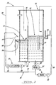
- the engine components 20 and the accessory components 22 are individually supply with lubricant. This is accomplished through the use of a lubrication system 24 comprising first and second separate lubricant circulating circuits 26 and 28. In this way, the engine components 20 have their own lubrication circuit and the accessory components 22 have another lubrication circuit.
- the circuits 26 and 28 are connected to a single supply tank 30 having first and second separate chambers 32 and 34.
- the first lubricant circuit 26 is connected in fluid flow communication with the first chamber 32
- the second lubricant circulating circuit 28 is connected in fluid flow communication with the second chamber 34.
- the supply tank 30 has two separate chambers, one for supplying lubricant to the engine components 20 and one for supplying lubricant to the accessory components 22.
- a partition wall 36 is provided within the tank 30 to prevent lubricant contained in the first chamber 32 from flowing into the second chamber 34 and vice versa.
- the supply tank 30 comprises a single filler port 38 through which a lubricant, such as virgin oil, can be fed to fill the first chamber 32.
- the second chamber 34 is filled via a filling and level maintaining circuit 40 connected in fluid flow communication with the first lubricant circulating circuit 26. Accordingly, the operator does not have to unscrew the cap of a second filler port for initially filling the second chamber 34.
- the second chamber 34 is filled from the first chamber 32, preferably through a filter 52 to insure complete segregation of the engine and the accessories oil systems. This contributes to reduce the chances for human error in filling the tank 30.
- the filling and level maintaining circuit 40 includes a feed line 42 having a downstream end connected to the first lubricant circulating circuit 26 and an upstream end connected to a nozzle 44 for discharging filtered lubricant into a scupper 46.
- the scupper 46 forms a receptacle having a hole or an orifice 48 defined in the bottom thereof for allowing lubricant to pass from the scupper 46 into the second chamber 34.
- a pump 50 is provided in the first lubricant circulating circuit 26 for withdrawing lubricant from the first chamber 32. Filling of the second chamber 34 is effected by operating the pump 50. Indeed, a portion of the lubricant pumped from the first chamber 32 will flow through the filter 52 and the feed line 42 before being discharged into the scupper 46 by the nozzle 44. The lubricant will then flow from the scupper 46 into the second chamber 34 until the level of lubricant in the second chamber 34 reaches the level of lubricant in the scupper 46. That is to say that the level of lubricant in the second chamber 34 is set by the scupper 46.
- the continuous flow of lubricant discharged from the nozzle 44 spills over the scupper 46 to the engine before being pumped back into the first chamber 32.
- the lubricant fed to the second chamber 34 is pumped through the filter 52, whereby it is always free from contaminant that might be present in the engine components.
- a one-way valve 54 or the like may be placed in the orifice 48 to prevent lubricant to pass from the second chamber 34 into the scupper 46. This prevents contamination of the lubricant circulated in the first circuit 26 by the lubricant circulated in the second circuit 28.
- a second portion of the lubricant pumped from the first chamber 32 is directed to the engine components 20, through the filter 52, and pumped back into the first chamber 32 by scavenge pumps 56.
- Various equipments, such as coolers, aerators and filters may be provided in the return lines of the first circuit 26, as is well known in the art.
- the second circuit 28 comprises a pump 58 for pumping lubricant from the second chamber 34 to the accessories components 22.
- Scavenge pumps 60 are provided downstream of the accessory components 22 for pumping the lubricant back into the second chamber 34.
- various equipments may be provided in the second circuit 28 to treat the lubricant before it is returned into the second chamber 34.
- the supply tank 30 is provided with a single level indicator 62 for monitoring the level of lubricant in the first chamber 32.
- the level indicator 62 can be provided in the form of a sight-glass.
- the level of lubricant in the second chamber 34 does not have to be monitored since it is maintained substantially constant by the continuous flow of lubricant from the first chamber 32 to the scupper 46. Indeed, as soon as the level of lubricant in the second chamber 34 starts to fall due to lubricant consumption of the accessory lubricant circuit 28, a corresponding amount of lubricant flows from the scupper 46 into the second chamber 34 through the orifice 48, thereby ensuring a constant level of lubricant in the second chamber 34.
- a drain 64 is provided in the base of each chamber 32 and 34.
- a dual independent tank 30 with a single filling port and a single level indicator is advantageous in that it provides space saving, while at the same time facilitating the maintenance of the lubrication system 24. It also contributes to minimize the number of piece composing the lubrication system and, thus, advantageously minimize the cost and the weight of the overall system.
Landscapes
- Engineering & Computer Science (AREA)
- Mechanical Engineering (AREA)
- General Engineering & Computer Science (AREA)
- Lubrication Of Internal Combustion Engines (AREA)
- Lubrication Details And Ventilation Of Internal Combustion Engines (AREA)
- General Details Of Gearings (AREA)
Claims (16)
- Schmiersystem (24) zum Schmieren von Gasturbinenmaschinenkomponenten (20) und Zubehörkomponenten (22) in separater Weise, aufweisend:einen ersten und einen zweiten Schmiermittelkreislauf (26, 28) zum separaten Zuführen von Schiermittel zu den Maschinenkomponenten (20) und den Zubehörkomponenten (22), sowieeinen Vorrratsbehälter (30);dadurch gekennzeichnet, dass der Behälter (30) eine erste und eine zweite separate Kammer (32, 34) aufweist, die mit dem ersten bzw. mit dem zweiten Schmiermittelkreislauf (26, 28) in Fluidströmungsverbindung stehen; und
dass das System ferner eine Einfüllöffnung (38) zum Befüllen der ersten Kammer (32) mit Schmiermittel sowie einen Befüllungs- und Füllstandhaltekreislauf (40) aufweist, der mit dem ersten Schmiermittelkreislauf (26) verbunden ist, um einen Teil des aus der ersten Kammer (32) gepumpten Schmierfluids in die zweite Kammer (34) zu leiten, so dass die zweite Kammer (34) zu Beginn befüllt werden kann und der Stand des darin enthaltenen Schmiermittels anschließend auf einem vorbestimmten Niveau gehalten werden kann. - Schmiersystem (24) nach Anspruch 1,
weiterhin mit einer Pumpe (50) zum Pumpen von Schmiermittel von der ersten Kammer (32) zu den Maschinenkomponenten (20) und zu der zweiten Kammer (34), wobei der Befüllungs- und Füllstandhaltekreislauf (40) das aus der ersten Kammer (32) gepumpte Schmiermittel in eine Auffangeinrichtung (46) abgibt, die mit der zweiten Kammer (34) in Fluidströmungsverbindung steht, wobei das Niveau des Schmiermittels in der zweiten Kammer (34) von dem Niveau des Schmiermittels in der Auffangeinrichtung (46) sowie von der Position der Auffangeinrichtung (46) in Relation zu der zweiten Kammer (34) abhängig ist. - Schmiersystem (24) nach Anspruch 2,
wobei eine überschüssige Strömung von dem Befüllungs- und Füllstandhaltekreislauf (40) den Maschinenkomponenten (20) zugeführt wird, wenn das Schmierfluid über die Auffangeinrichtung (46) überläuft. - Schmiersystem (24) nach Anspruch 2 oder 3,
wobei die Auffangeinrichtung (46) eine zu der zweiten Kammer (34) führende Öffnung (48) bildet und wobei ein Einwegventil (54) vorgesehen ist, um zu verhindern, dass das in der zweiten Kammer (34) enthaltene Schmiermittel durch die Öffnung (48) in die Auffangeinrichtung (46) strömt. - Schmiersystem (24) nach Anspruch 2, 3 oder 4,
wobei der Befüllungs- und Füllstandhaltekreislauf (40) eine Düse (44) beinhaltet, die zum Abgeben einer kontinuierlichen Strömung von Schmiermittel in die Auffangeinrichtung (46) ausgebildet ist. - Schmiersystem (24) nach einem der vorausgehenden Ansprüche,
wobei die erste und die zweite Kammer (32, 34) eine gemeinsame Abzugseinrichtung aufweisen. - Schmiersystem (24) nach einem der Ansprüche 2 bis 6,
wobei das von der ersten Kammer (32) abgezogene Schmiermittel durch einen Filter (52) geleitet wird, bevor es in die zweite Kammer (34) geleitet wird. - Schmiersystem (24) nach einem der vorausgehenden Ansprüche,
wobei der Vorratsbehälter (30) eine einzige Schmiermittelstand-Anzeige (62) zum Überwachen des Niveaus des Schmiermittels in der ersten Kammer (32) aufweist, wobei das Niveau des Schmiermittels in der zweiten Kammer (34) durch die Strömung des Schmiermittels durch den Befüllungs- und Füllstandhaltekreislauf (40) hindurch im Wesentlichen konstant gehalten wird. - Schmiersystem (24) nach Anspruch 1,
wobei die Einfüllöffnung (38) in dem Vorratsbehälter (30) ausgebildet ist, sowie weiterhin mit einer Pumpe (50) zum Abziehen von Schmiermittel aus der ersten Kammer (32), wobei ein erster Teil des aus der ersten Kammer (32) gepumpten Schmiermittels über den ersten Schmiermittelkreislauf (26) zu den Maschinenkomponenten (20) geleitet wird, bevor er zu der ersten Kammer (32) zurückgeleitet wird, während ein zweiter Teil des aus der ersten Kammer (32) gepumpten Schmierfluids durch den Befüllungs- und Füllstandhaltekreislauf (40) in die zweite Kammer (34) geleitet wird. - Schmiersystem (24) nach Anspruch 9,
wobei der Befüllungs- und Füllstandhaltekreislauf (40) eine Auffangeinrichtung (46) aufweist, die in Fluidströmungsverbindung mit der zweiten Kammer (34) steht, wobei die Auffangeinrichtung (46) eine Aufnahme zum Aufnehmen einer kontinuierlichen Strömung des Schmiermittels von der ersten Kammer (32) bildet, wobei die Auffangeinrichtung (46) in Überlauf-Übertragungsbeziehung zu dem ersten Satz von Komponenten (20) steht, um eine Rezirkulation von der Auffangeinrichtung (46) zugeführtem, überschüssigen Schmiermittel durch den ersten Schmiermittelkreislauf (26) zu ermöglichen. - Schmiersystem (24) nach Anspruch 10,
wobei die Auffangeinrichtung (46) eine in die zweite Kammer (34) führende Öffnung (48) bildet, um ein Strömen von Schmiermittel von der Auffangeinrichtung (46) in die zweite Kammer (34) zu ermöglichen, um Schmiermittelverluste in dem zweiten Schmiermittelkreislauf (28) automatisch zu kompensieren. - Schmiersystem (24) nach Anspruch 9,
wobei der Befüllungs- und Füllstandhaltekreislauf (40) eine Auffangeinrichtung (46) aufweist, die ein Reservoir zum automatischen Zuführen von Schmiermittel zu der zweiten Kammer (34) bildet, um den Schmiermittelverbrauch des zweiten Satzes von Komponenten (22) zu kompensieren, während in die Auffangeinrichtung (46) strömendes, überschüssiges Schmiermittel zu dem ersten Schmiermittelkreislauf (26) zurückgeführt werden kann. - Schmiersystem (24) nach Anspruch 12,
wobei die Auffangeinrichtung (46) das Niveau des Schmiermittels in der zweiten Kammer (34) vorgibt. - Schmiersystem (24) nach Anspruch 12 oder 13,
wobei der Befüllungs- und Füllstandhaltekreislauf (40) eine Düse (44) aufweist, die eine kontinuierlichen Strömung von Schmiermittel in das Reservoir abgibt. - Schmiersystem (24) nach einem der Ansprüche 9 bis 15,
wobei die erste und die zweite Kammer (32, 34) eine gemeinsame Abzugseinrichtung aufweisen. - Schmiersystem (26) nach einem der Ansprüche 9 bis 15,
wobei der Vorratsbehälter (30) eine einzige Schmiermittelstand-Anzeige (62) zum Überwachen des Niveaus des Schmiermittels in der ersten Kammer (32) aufweist, wobei das Niveau des Schmiermittels in der zweiten Kammer (34) durch die Strömung des Schmiermittels durch den Befüllungs- und Füllstandhaltekreislauf (40) hindurch im Wesentlichen konstant gehalten wird.
Applications Claiming Priority (3)
| Application Number | Priority Date | Filing Date | Title |
|---|---|---|---|
| US200755 | 2002-07-24 | ||
| US10/200,755 US6793042B2 (en) | 2002-07-24 | 2002-07-24 | Dual independent tank and oil system with single port filling |
| PCT/CA2003/001009 WO2004009962A1 (en) | 2002-07-24 | 2003-07-08 | Dual independent tank and oil system with single port filling |
Publications (2)
| Publication Number | Publication Date |
|---|---|
| EP1546511A1 EP1546511A1 (de) | 2005-06-29 |
| EP1546511B1 true EP1546511B1 (de) | 2008-02-13 |
Family
ID=30769560
Family Applications (1)
| Application Number | Title | Priority Date | Filing Date |
|---|---|---|---|
| EP03764839A Expired - Lifetime EP1546511B1 (de) | 2002-07-24 | 2003-07-08 | Unabhängiges doppeltank- und ölsystem mit einer einfüllöffnung |
Country Status (5)
| Country | Link |
|---|---|
| US (1) | US6793042B2 (de) |
| EP (1) | EP1546511B1 (de) |
| CA (1) | CA2487978C (de) |
| DE (1) | DE60319109T2 (de) |
| WO (1) | WO2004009962A1 (de) |
Families Citing this family (46)
| Publication number | Priority date | Publication date | Assignee | Title |
|---|---|---|---|---|
| DE102008009825A1 (de) * | 2008-02-19 | 2009-08-20 | Rolls-Royce Deutschland Ltd & Co Kg | Fluggasturbinenöltank mit Füllstandsanzeige |
| US8181746B2 (en) | 2008-09-18 | 2012-05-22 | United Technologies Corporation | Continuous supply fluid reservoir |
| US8017073B2 (en) * | 2008-11-28 | 2011-09-13 | Life Spring Limited Partnership | High intensity air purifier |
| US8307626B2 (en) * | 2009-02-26 | 2012-11-13 | United Technologies Corporation | Auxiliary pump system for fan drive gear system |
| US8051869B2 (en) * | 2009-05-22 | 2011-11-08 | United Technologies Corporation | Gravity operated valve |
| US8230974B2 (en) * | 2009-05-22 | 2012-07-31 | United Technologies Corporation | Windmill and zero gravity lubrication system for a gas turbine engine |
| US8511055B2 (en) * | 2009-05-22 | 2013-08-20 | United Technologies Corporation | Apparatus and method for providing damper liquid in a gas turbine |
| US8381878B2 (en) * | 2009-11-12 | 2013-02-26 | United Technologies Corporation | Oil capture and bypass system |
| CA2715920A1 (en) * | 2010-02-08 | 2011-08-08 | Mitsubishi Heavy Industries, Ltd. | Lubricant heating mechanism, gear mechanism, and wind turbine generator using the same |
| US8845898B2 (en) | 2010-07-07 | 2014-09-30 | Hamilton Sundstrand Corporation | APU fuel filter housing scupper |
| EP2434128A1 (de) * | 2010-09-22 | 2012-03-28 | Siemens Aktiengesellschaft | Ölversorgungssystem für eine stationäre Turbomaschine |
| US9222618B2 (en) | 2010-11-29 | 2015-12-29 | Lincoln Industrial Corporation | Stepper motor driving a lubrication pump providing uninterrupted lubricant flow |
| US8844679B2 (en) | 2010-11-29 | 2014-09-30 | Lincoln Industrial Corporation | Pump having venting and non-venting piston return |
| US9388940B2 (en) | 2010-11-29 | 2016-07-12 | Lincoln Industrial Corporation | Variable speed stepper motor driving a lubrication pump system |
| US9458923B2 (en) | 2011-03-31 | 2016-10-04 | Textron Innovations Inc. | Gearbox with passive lubrication system |
| US8915331B2 (en) | 2011-09-29 | 2014-12-23 | Lincoln Industrial Corporation | Battery powered, handheld lubrication gun with display |
| US9086186B2 (en) | 2011-10-14 | 2015-07-21 | Lincoln Industrial Corporation | System having removable lubricant reservoir and lubricant refilling station |
| US8984884B2 (en) | 2012-01-04 | 2015-03-24 | General Electric Company | Waste heat recovery systems |
| US9024460B2 (en) * | 2012-01-04 | 2015-05-05 | General Electric Company | Waste heat recovery system generator encapsulation |
| US9018778B2 (en) * | 2012-01-04 | 2015-04-28 | General Electric Company | Waste heat recovery system generator varnishing |
| US9140246B2 (en) | 2012-03-19 | 2015-09-22 | Lincoln Industrial Corporation | Lance pump having vertically mounted stepper motor |
| US9239044B2 (en) | 2012-03-19 | 2016-01-19 | Lincoln Industrial Corporation | Lance pump having horizontally mounted stepper/servo motor |
| US8978825B2 (en) | 2012-04-19 | 2015-03-17 | Lincoln Industrial Corporation | Dual-line pump unit, lubrication system, and related apparatus and method |
| US9127809B2 (en) * | 2012-04-19 | 2015-09-08 | Lincoln Industrial Corporation | Multi-chamber pump system |
| US20140090930A1 (en) | 2012-09-28 | 2014-04-03 | United Technologies Corporation | Multiple reservoir lubrication system |
| US9206741B2 (en) | 2012-11-30 | 2015-12-08 | United Technologies Corporation | Fluid system with gravity controlled valve |
| WO2014123863A2 (en) * | 2013-02-06 | 2014-08-14 | United Technologies Corporation | Multi-circuit lubrication system for a turbine engine |
| US9353848B2 (en) | 2013-03-13 | 2016-05-31 | Hamilton Sundstrand Corporation | Spline lubrication system |
| FR3005486B1 (fr) * | 2013-05-07 | 2017-08-18 | Snecma | Lubrification dans une turbomachine |
| FR3010133B1 (fr) * | 2013-09-02 | 2015-10-02 | Snecma | Reservoir comprenant une cloison inclinee munie a ses extremites d'orifices traversants pour une alimentation continue de turbomachine en liquide d'alimentation |
| US9671065B2 (en) | 2013-10-17 | 2017-06-06 | Lincoln Industrial Corporation | Pump having wear and wear rate detection |
| US10030676B2 (en) | 2014-04-23 | 2018-07-24 | Hyster—Yale Group, Inc. | Hydraulic fluid supply apparatus and methods |
| FR3045764B1 (fr) * | 2015-12-17 | 2017-12-22 | Airbus Helicopters | Dispositif de lubrification de secours a architecture simplifiee pour une boite de transmission principale de puissance d'un aeronef |
| US10634053B2 (en) | 2015-12-21 | 2020-04-28 | United Technologies Corporation | Electric windmill pump for gearbox durability |
| BE1024639B1 (fr) * | 2016-10-13 | 2018-05-16 | Safran Aero Boosters S.A. | Reservoir d'huile de turbomachine |
| US10711644B2 (en) * | 2017-04-24 | 2020-07-14 | Raytheon Technologies Corporation | Method and system to ensure full oil tubes after gas turbine engine shutdown |
| DE102017128483A1 (de) * | 2017-11-30 | 2019-06-06 | Rolls-Royce Deutschland Ltd & Co Kg | Flugtriebwerk |
| GB201807200D0 (en) * | 2018-05-02 | 2018-06-13 | Rolls Royce Plc | Oil tank filling system |
| GB201807201D0 (en) * | 2018-05-02 | 2018-06-13 | Rolls Royce Plc | Oil tank filling system |
| GB2589562B (en) * | 2019-11-15 | 2024-11-06 | Cummins Inc | Lubrication fluid drainage system |
| RU2742591C1 (ru) * | 2019-11-21 | 2021-02-08 | Общество с ограниченной ответственностью "ГАЗПРОМ ТРАНСГАЗ МОСКВА" | Система смазки газоперекачивающего агрегата со стационарным газотурбинным двигателем |
| DE102021118933A1 (de) | 2021-07-21 | 2023-01-26 | Rolls-Royce Deutschland Ltd & Co Kg | Vorrichtung zur Ölschmierung einer drehfesten Verbindung zwischen zwei Wellen |
| US12320418B2 (en) * | 2022-06-22 | 2025-06-03 | General Electric Company | Gearbox assembly with lubricant extraction volume ratio |
| US12326115B2 (en) * | 2022-06-22 | 2025-06-10 | General Electric Company | Gearbox assembly with lubricant extraction volume ratio |
| US12276333B2 (en) * | 2023-06-21 | 2025-04-15 | General Electric Company | Gearbox assembly lubrication system for a turbine engine |
| US20260227029A1 (en) * | 2025-02-06 | 2026-08-06 | Pratt & Whitney Canada Corp. | Lubricant system for aircraft |
Family Cites Families (16)
| Publication number | Priority date | Publication date | Assignee | Title |
|---|---|---|---|---|
| US3960174A (en) * | 1974-09-03 | 1976-06-01 | Caterpillar Tractor Co. | Hydraulic circuit with dual tank system and method for using the same |
| US4002224A (en) * | 1975-02-26 | 1977-01-11 | Westinghouse Electric Corporation | Turbine lubrication and emergency gas system |
| US4105093A (en) * | 1977-02-03 | 1978-08-08 | Westinghouse Electric Corp. | Control system for pressurized lubricating system |
| US4157744A (en) * | 1977-07-18 | 1979-06-12 | Capriotti Lawrence J | Lubricating and cooling engine system component |
| GB2059517B (en) * | 1979-09-29 | 1983-06-22 | Rolls Royce | Lubrication system |
| DE3137947C2 (de) * | 1980-09-26 | 1983-10-27 | Rolls-Royce Ltd., London | Für beliebige Flugmanöver taugliches Schmierölsystem für Gasturbinentriebwerke |
| DE3242366C2 (de) * | 1982-11-16 | 1985-02-07 | MTU Motoren- und Turbinen-Union München GmbH, 8000 München | Ölversorgungseinrichtung für beliebigen Flugsituationen aussetzbare Gasturbinentriebwerke |
| FR2607185B1 (fr) * | 1986-11-20 | 1990-05-04 | Snecma | Systeme de lubrification pour demarreur de turbomachine |
| US4856273A (en) * | 1988-07-21 | 1989-08-15 | General Motors Corporation | Secondary oil system for gas turbine engine |
| US4947963A (en) * | 1989-05-11 | 1990-08-14 | United Technologies Corporation | Oil supply reservoir |
| US5400889A (en) * | 1993-09-21 | 1995-03-28 | Agco Corporation | Clutch assembly with automatic oil level control system |
| US5565094A (en) * | 1994-08-30 | 1996-10-15 | Nelson Industries, Inc. | Apparatus for purifying and conditioning turbine lubricating oil |
| US5611411A (en) * | 1996-05-10 | 1997-03-18 | Florida Power Corporation | Turbine lubrication oil filtration safeguard system |
| DE19925779B4 (de) | 1999-06-05 | 2014-01-23 | Abb Turbo Systems Ag | Abgasturbolader mit einem Notöltank |
| GB0016198D0 (en) | 2000-06-30 | 2000-08-23 | Lucas Industries Ltd | Fluid reservoir |
| US20030079710A1 (en) * | 2001-10-26 | 2003-05-01 | David Webster | Lubrication system for a powertrain |
-
2002
- 2002-07-24 US US10/200,755 patent/US6793042B2/en not_active Expired - Lifetime
-
2003
- 2003-07-08 WO PCT/CA2003/001009 patent/WO2004009962A1/en not_active Ceased
- 2003-07-08 DE DE60319109T patent/DE60319109T2/de not_active Expired - Lifetime
- 2003-07-08 EP EP03764839A patent/EP1546511B1/de not_active Expired - Lifetime
- 2003-07-08 CA CA2487978A patent/CA2487978C/en not_active Expired - Fee Related
Also Published As
| Publication number | Publication date |
|---|---|
| CA2487978A1 (en) | 2004-01-29 |
| WO2004009962A1 (en) | 2004-01-29 |
| US20040016601A1 (en) | 2004-01-29 |
| CA2487978C (en) | 2011-10-11 |
| US6793042B2 (en) | 2004-09-21 |
| DE60319109D1 (de) | 2008-03-27 |
| EP1546511A1 (de) | 2005-06-29 |
| DE60319109T2 (de) | 2009-02-05 |
Similar Documents
| Publication | Publication Date | Title |
|---|---|---|
| US6793042B2 (en) | Dual independent tank and oil system with single port filling | |
| US12018574B2 (en) | Geared gas turbine engine with oil deaerator and air removal | |
| US4531358A (en) | Oil system for aircraft gas turbine engine | |
| US8020665B2 (en) | Lubrication system with extended emergency operability | |
| CA2733072C (en) | Oil supply system with main pump deaeration | |
| EP2898202B1 (de) | Schmiersystem mit porösen merkmalen | |
| EP2166195B1 (de) | Flüssigkeitsbehälter in einer Gasturbine | |
| US20020195296A1 (en) | System for lubricating and cooling a mechanical assembly | |
| GB1597404A (en) | Auxiliary oil supply systems | |
| US10844948B2 (en) | Lubrication device having a plurality of lubrication liquid recovery tanks, and optimized and reliable delivery means to a main tank | |
| US8679226B2 (en) | Vacuum system for membrane fuel stabilization unit | |
| US20020007982A1 (en) | Oil system | |
| GB2084266A (en) | Oil system for aircraft gas turbine engine | |
| US20020000479A1 (en) | Fluid reservoir | |
| GB2381294A (en) | I.c. engine with increased lubricant capacity | |
| KR102018747B1 (ko) | 윤활액이 담긴 복수의 리커버리 탱크와 메인 탱크로의 최적화되고 믿을 수 있는 전달 수단이 제공된 윤활 장치 | |
| CN109869618B (zh) | 设有多个润滑液回收槽罐以及至主槽罐的优化且可靠的输送装置的润滑装置 |
Legal Events
| Date | Code | Title | Description |
|---|---|---|---|
| PUAI | Public reference made under article 153(3) epc to a published international application that has entered the european phase |
Free format text: ORIGINAL CODE: 0009012 |
|
| 17P | Request for examination filed |
Effective date: 20050223 |
|
| AK | Designated contracting states |
Kind code of ref document: A1 Designated state(s): AT BE BG CH CY CZ DE DK EE ES FI FR GB GR HU IE IT LI LU MC NL PT RO SE SI SK TR |
|
| RBV | Designated contracting states (corrected) |
Designated state(s): DE FR GB |
|
| GRAP | Despatch of communication of intention to grant a patent |
Free format text: ORIGINAL CODE: EPIDOSNIGR1 |
|
| GRAS | Grant fee paid |
Free format text: ORIGINAL CODE: EPIDOSNIGR3 |
|
| GRAA | (expected) grant |
Free format text: ORIGINAL CODE: 0009210 |
|
| AK | Designated contracting states |
Kind code of ref document: B1 Designated state(s): DE FR GB |
|
| REG | Reference to a national code |
Ref country code: GB Ref legal event code: FG4D |
|
| REF | Corresponds to: |
Ref document number: 60319109 Country of ref document: DE Date of ref document: 20080327 Kind code of ref document: P |
|
| ET | Fr: translation filed | ||
| PLBE | No opposition filed within time limit |
Free format text: ORIGINAL CODE: 0009261 |
|
| STAA | Information on the status of an ep patent application or granted ep patent |
Free format text: STATUS: NO OPPOSITION FILED WITHIN TIME LIMIT |
|
| 26N | No opposition filed |
Effective date: 20081114 |
|
| PGFP | Annual fee paid to national office [announced via postgrant information from national office to epo] |
Ref country code: FR Payment date: 20110727 Year of fee payment: 9 |
|
| PGFP | Annual fee paid to national office [announced via postgrant information from national office to epo] |
Ref country code: GB Payment date: 20110706 Year of fee payment: 9 Ref country code: DE Payment date: 20110706 Year of fee payment: 9 |
|
| GBPC | Gb: european patent ceased through non-payment of renewal fee |
Effective date: 20120708 |
|
| REG | Reference to a national code |
Ref country code: FR Ref legal event code: ST Effective date: 20130329 |
|
| PG25 | Lapsed in a contracting state [announced via postgrant information from national office to epo] |
Ref country code: DE Free format text: LAPSE BECAUSE OF NON-PAYMENT OF DUE FEES Effective date: 20130201 Ref country code: FR Free format text: LAPSE BECAUSE OF NON-PAYMENT OF DUE FEES Effective date: 20120731 Ref country code: GB Free format text: LAPSE BECAUSE OF NON-PAYMENT OF DUE FEES Effective date: 20120708 |
|
| REG | Reference to a national code |
Ref country code: DE Ref legal event code: R119 Ref document number: 60319109 Country of ref document: DE Effective date: 20130201 |