EP1546320B1 - Im nanomassstab konstruierte biophotonische hybridvorrichtung - Google Patents
Im nanomassstab konstruierte biophotonische hybridvorrichtung Download PDFInfo
- Publication number
- EP1546320B1 EP1546320B1 EP03794664.7A EP03794664A EP1546320B1 EP 1546320 B1 EP1546320 B1 EP 1546320B1 EP 03794664 A EP03794664 A EP 03794664A EP 1546320 B1 EP1546320 B1 EP 1546320B1
- Authority
- EP
- European Patent Office
- Prior art keywords
- chlorosomes
- light
- photosensitive
- hybrid
- photosensitive semiconductor
- Prior art date
- Legal status (The legal status is an assumption and is not a legal conclusion. Google has not performed a legal analysis and makes no representation as to the accuracy of the status listed.)
- Expired - Lifetime
Links
- 238000000034 method Methods 0.000 claims description 81
- 241000192731 Chloroflexus aurantiacus Species 0.000 claims description 38
- 210000004027 cell Anatomy 0.000 claims description 37
- 238000013400 design of experiment Methods 0.000 claims description 34
- 239000004065 semiconductor Substances 0.000 claims description 33
- 241000894006 Bacteria Species 0.000 claims description 32
- CMAUHAKVZHVPCD-VFZPPMCZSA-M bchl c Chemical compound [Mg+2].CC(O)C1=C(C)C(=C2C)[N-]C1=CC(C(=C1)C)=NC1=CC([N-]1)=CC(C(=O)C3)=C1C3=C1[C@@H](CCC(=O)OC\C=C(/C)CC\C=C(/C)CCC=C(C)C)[C@H](C)C2=N1 CMAUHAKVZHVPCD-VFZPPMCZSA-M 0.000 claims description 21
- 238000012546 transfer Methods 0.000 claims description 21
- 238000004519 manufacturing process Methods 0.000 claims description 14
- 230000007613 environmental effect Effects 0.000 claims description 13
- 230000000243 photosynthetic effect Effects 0.000 claims description 13
- 230000004044 response Effects 0.000 claims description 13
- XUIMIQQOPSSXEZ-UHFFFAOYSA-N Silicon Chemical compound [Si] XUIMIQQOPSSXEZ-UHFFFAOYSA-N 0.000 claims description 10
- 229910052710 silicon Inorganic materials 0.000 claims description 10
- 239000010703 silicon Substances 0.000 claims description 10
- 238000001429 visible spectrum Methods 0.000 claims description 8
- 230000004298 light response Effects 0.000 claims description 7
- 235000021466 carotenoid Nutrition 0.000 claims description 6
- 150000001747 carotenoids Chemical class 0.000 claims description 6
- 230000006978 adaptation Effects 0.000 claims description 5
- 210000000170 cell membrane Anatomy 0.000 claims description 5
- 230000003292 diminished effect Effects 0.000 claims description 5
- 230000005661 hydrophobic surface Effects 0.000 claims description 5
- 230000001464 adherent effect Effects 0.000 claims description 4
- 238000012986 modification Methods 0.000 claims description 4
- 230000004048 modification Effects 0.000 claims description 4
- 241000894007 species Species 0.000 claims description 3
- 230000001086 cytosolic effect Effects 0.000 claims 1
- 238000002835 absorbance Methods 0.000 description 43
- 238000013461 design Methods 0.000 description 38
- 230000003993 interaction Effects 0.000 description 26
- 238000002474 experimental method Methods 0.000 description 25
- 239000000523 sample Substances 0.000 description 24
- 238000010790 dilution Methods 0.000 description 18
- 239000012895 dilution Substances 0.000 description 18
- 230000012010 growth Effects 0.000 description 18
- 239000000243 solution Substances 0.000 description 18
- 238000013459 approach Methods 0.000 description 17
- 238000004458 analytical method Methods 0.000 description 14
- 239000000463 material Substances 0.000 description 13
- 238000001228 spectrum Methods 0.000 description 13
- XLYOFNOQVPJJNP-UHFFFAOYSA-N water Chemical compound O XLYOFNOQVPJJNP-UHFFFAOYSA-N 0.000 description 13
- 238000000862 absorption spectrum Methods 0.000 description 12
- 239000000872 buffer Substances 0.000 description 12
- 238000011161 development Methods 0.000 description 12
- 230000000694 effects Effects 0.000 description 12
- 230000015556 catabolic process Effects 0.000 description 11
- 239000006059 cover glass Substances 0.000 description 11
- 238000006731 degradation reaction Methods 0.000 description 11
- 230000003044 adaptive effect Effects 0.000 description 10
- 238000002955 isolation Methods 0.000 description 9
- 230000035945 sensitivity Effects 0.000 description 9
- FAPWRFPIFSIZLT-UHFFFAOYSA-M Sodium chloride Chemical compound [Na+].[Cl-] FAPWRFPIFSIZLT-UHFFFAOYSA-M 0.000 description 8
- 230000003287 optical effect Effects 0.000 description 8
- 238000012545 processing Methods 0.000 description 8
- 230000003595 spectral effect Effects 0.000 description 8
- 238000000540 analysis of variance Methods 0.000 description 7
- 239000005388 borosilicate glass Substances 0.000 description 7
- 238000010586 diagram Methods 0.000 description 7
- 238000001704 evaporation Methods 0.000 description 7
- 239000011521 glass Substances 0.000 description 7
- 230000002209 hydrophobic effect Effects 0.000 description 7
- 239000000049 pigment Substances 0.000 description 7
- 230000000638 stimulation Effects 0.000 description 7
- 239000000758 substrate Substances 0.000 description 7
- LENZDBCJOHFCAS-UHFFFAOYSA-N tris Chemical compound OCC(N)(CO)CO LENZDBCJOHFCAS-UHFFFAOYSA-N 0.000 description 7
- 238000004630 atomic force microscopy Methods 0.000 description 6
- 230000015572 biosynthetic process Effects 0.000 description 6
- 238000004364 calculation method Methods 0.000 description 6
- 238000006243 chemical reaction Methods 0.000 description 6
- 230000006378 damage Effects 0.000 description 6
- 230000001419 dependent effect Effects 0.000 description 6
- 238000003384 imaging method Methods 0.000 description 6
- 239000010410 layer Substances 0.000 description 6
- 238000003860 storage Methods 0.000 description 6
- 238000012360 testing method Methods 0.000 description 6
- 239000012153 distilled water Substances 0.000 description 5
- 238000005286 illumination Methods 0.000 description 5
- 238000011534 incubation Methods 0.000 description 5
- 238000005259 measurement Methods 0.000 description 5
- 230000008569 process Effects 0.000 description 5
- 239000000047 product Substances 0.000 description 5
- 238000007789 sealing Methods 0.000 description 5
- CIWBSHSKHKDKBQ-JLAZNSOCSA-N Ascorbic acid Chemical compound OC[C@H](O)[C@H]1OC(=O)C(O)=C1O CIWBSHSKHKDKBQ-JLAZNSOCSA-N 0.000 description 4
- 239000004593 Epoxy Substances 0.000 description 4
- 229910021578 Iron(III) chloride Inorganic materials 0.000 description 4
- 239000007983 Tris buffer Substances 0.000 description 4
- 230000002596 correlated effect Effects 0.000 description 4
- 238000000445 field-emission scanning electron microscopy Methods 0.000 description 4
- RBTARNINKXHZNM-UHFFFAOYSA-K iron trichloride Chemical compound Cl[Fe](Cl)Cl RBTARNINKXHZNM-UHFFFAOYSA-K 0.000 description 4
- 239000007788 liquid Substances 0.000 description 4
- 239000000203 mixture Substances 0.000 description 4
- 239000008188 pellet Substances 0.000 description 4
- 238000001782 photodegradation Methods 0.000 description 4
- 239000011780 sodium chloride Substances 0.000 description 4
- 238000001179 sorption measurement Methods 0.000 description 4
- 238000004611 spectroscopical analysis Methods 0.000 description 4
- 238000003786 synthesis reaction Methods 0.000 description 4
- 229930006000 Sucrose Natural products 0.000 description 3
- CZMRCDWAGMRECN-UGDNZRGBSA-N Sucrose Chemical compound O[C@H]1[C@H](O)[C@@H](CO)O[C@@]1(CO)O[C@@H]1[C@H](O)[C@@H](O)[C@H](O)[C@@H](CO)O1 CZMRCDWAGMRECN-UGDNZRGBSA-N 0.000 description 3
- 230000002776 aggregation Effects 0.000 description 3
- 238000004220 aggregation Methods 0.000 description 3
- 238000004422 calculation algorithm Methods 0.000 description 3
- 229910052799 carbon Inorganic materials 0.000 description 3
- 230000008859 change Effects 0.000 description 3
- 238000001514 detection method Methods 0.000 description 3
- 230000008020 evaporation Effects 0.000 description 3
- 239000000835 fiber Substances 0.000 description 3
- 238000003306 harvesting Methods 0.000 description 3
- 239000002245 particle Substances 0.000 description 3
- 238000010791 quenching Methods 0.000 description 3
- 239000002356 single layer Substances 0.000 description 3
- 239000005720 sucrose Substances 0.000 description 3
- 238000002834 transmittance Methods 0.000 description 3
- IJGRMHOSHXDMSA-UHFFFAOYSA-N Atomic nitrogen Chemical compound N#N IJGRMHOSHXDMSA-UHFFFAOYSA-N 0.000 description 2
- 108010003118 Bacteriochlorophylls Proteins 0.000 description 2
- CSNNHWWHGAXBCP-UHFFFAOYSA-L Magnesium sulfate Chemical compound [Mg+2].[O-][S+2]([O-])([O-])[O-] CSNNHWWHGAXBCP-UHFFFAOYSA-L 0.000 description 2
- 206010034972 Photosensitivity reaction Diseases 0.000 description 2
- 238000003917 TEM image Methods 0.000 description 2
- 230000002745 absorbent Effects 0.000 description 2
- 239000002250 absorbent Substances 0.000 description 2
- 230000004075 alteration Effects 0.000 description 2
- DSJXIQQMORJERS-AGGZHOMASA-M bacteriochlorophyll a Chemical compound C1([C@@H](C(=O)OC)C(=O)C2=C3C)=C2N2C3=CC([C@H](CC)[C@H]3C)=[N+]4C3=CC3=C(C(C)=O)C(C)=C5N3[Mg-2]42[N+]2=C1[C@@H](CCC(=O)OC\C=C(/C)CCC[C@H](C)CCC[C@H](C)CCCC(C)C)[C@H](C)C2=C5 DSJXIQQMORJERS-AGGZHOMASA-M 0.000 description 2
- 230000008901 benefit Effects 0.000 description 2
- 230000005540 biological transmission Effects 0.000 description 2
- 238000004113 cell culture Methods 0.000 description 2
- 230000001413 cellular effect Effects 0.000 description 2
- 238000012512 characterization method Methods 0.000 description 2
- 239000003795 chemical substances by application Substances 0.000 description 2
- 239000011248 coating agent Substances 0.000 description 2
- 238000000576 coating method Methods 0.000 description 2
- 238000010276 construction Methods 0.000 description 2
- 230000001276 controlling effect Effects 0.000 description 2
- 230000000875 corresponding effect Effects 0.000 description 2
- 238000004925 denaturation Methods 0.000 description 2
- 230000036425 denaturation Effects 0.000 description 2
- 238000012938 design process Methods 0.000 description 2
- 238000009792 diffusion process Methods 0.000 description 2
- 238000009826 distribution Methods 0.000 description 2
- 238000012407 engineering method Methods 0.000 description 2
- 238000011156 evaluation Methods 0.000 description 2
- 239000012467 final product Substances 0.000 description 2
- 238000005755 formation reaction Methods 0.000 description 2
- XLYOFNOQVPJJNP-ZSJDYOACSA-N heavy water Substances [2H]O[2H] XLYOFNOQVPJJNP-ZSJDYOACSA-N 0.000 description 2
- 230000002427 irreversible effect Effects 0.000 description 2
- 239000012528 membrane Substances 0.000 description 2
- 230000036211 photosensitivity Effects 0.000 description 2
- FGIUAXJPYTZDNR-UHFFFAOYSA-N potassium nitrate Chemical compound [K+].[O-][N+]([O-])=O FGIUAXJPYTZDNR-UHFFFAOYSA-N 0.000 description 2
- 108090000623 proteins and genes Proteins 0.000 description 2
- 102000004169 proteins and genes Human genes 0.000 description 2
- 230000000171 quenching effect Effects 0.000 description 2
- 238000011160 research Methods 0.000 description 2
- VWDWKYIASSYTQR-UHFFFAOYSA-N sodium nitrate Chemical compound [Na+].[O-][N+]([O-])=O VWDWKYIASSYTQR-UHFFFAOYSA-N 0.000 description 2
- VGTPCRGMBIAPIM-UHFFFAOYSA-M sodium thiocyanate Chemical compound [Na+].[S-]C#N VGTPCRGMBIAPIM-UHFFFAOYSA-M 0.000 description 2
- 239000007787 solid Substances 0.000 description 2
- 239000002904 solvent Substances 0.000 description 2
- 238000003756 stirring Methods 0.000 description 2
- 239000000126 substance Substances 0.000 description 2
- 230000002277 temperature effect Effects 0.000 description 2
- 238000010200 validation analysis Methods 0.000 description 2
- QTBSBXVTEAMEQO-UHFFFAOYSA-M Acetate Chemical compound CC([O-])=O QTBSBXVTEAMEQO-UHFFFAOYSA-M 0.000 description 1
- 108010001478 Bacitracin Proteins 0.000 description 1
- OKTJSMMVPCPJKN-UHFFFAOYSA-N Carbon Chemical compound [C] OKTJSMMVPCPJKN-UHFFFAOYSA-N 0.000 description 1
- 229910021580 Cobalt(II) chloride Inorganic materials 0.000 description 1
- 101100453960 Drosophila melanogaster klar gene Proteins 0.000 description 1
- 229910004619 Na2MoO4 Inorganic materials 0.000 description 1
- QAOWNCQODCNURD-UHFFFAOYSA-N Sulfuric acid Chemical compound OS(O)(=O)=O QAOWNCQODCNURD-UHFFFAOYSA-N 0.000 description 1
- 238000002268 absorption detected magnetic resonance Methods 0.000 description 1
- 238000010521 absorption reaction Methods 0.000 description 1
- NIXOWILDQLNWCW-UHFFFAOYSA-N acrylic acid group Chemical group C(C=C)(=O)O NIXOWILDQLNWCW-UHFFFAOYSA-N 0.000 description 1
- 239000000654 additive Substances 0.000 description 1
- 230000000996 additive effect Effects 0.000 description 1
- 229910052925 anhydrite Inorganic materials 0.000 description 1
- 239000008346 aqueous phase Substances 0.000 description 1
- 238000003491 array Methods 0.000 description 1
- 229960005070 ascorbic acid Drugs 0.000 description 1
- 235000010323 ascorbic acid Nutrition 0.000 description 1
- 239000011668 ascorbic acid Substances 0.000 description 1
- 230000000712 assembly Effects 0.000 description 1
- 238000000429 assembly Methods 0.000 description 1
- 229960003071 bacitracin Drugs 0.000 description 1
- 229930184125 bacitracin Natural products 0.000 description 1
- CLKOFPXJLQSYAH-ABRJDSQDSA-N bacitracin A Chemical compound C1SC([C@@H](N)[C@@H](C)CC)=N[C@@H]1C(=O)N[C@@H](CC(C)C)C(=O)N[C@H](CCC(O)=O)C(=O)N[C@@H]([C@@H](C)CC)C(=O)N[C@@H]1C(=O)N[C@H](CCCN)C(=O)N[C@@H]([C@@H](C)CC)C(=O)N[C@H](CC=2C=CC=CC=2)C(=O)N[C@@H](CC=2N=CNC=2)C(=O)N[C@H](CC(O)=O)C(=O)N[C@@H](CC(N)=O)C(=O)NCCCC1 CLKOFPXJLQSYAH-ABRJDSQDSA-N 0.000 description 1
- 230000001580 bacterial effect Effects 0.000 description 1
- 239000012620 biological material Substances 0.000 description 1
- 230000007321 biological mechanism Effects 0.000 description 1
- 230000003592 biomimetic effect Effects 0.000 description 1
- 238000004820 blood count Methods 0.000 description 1
- 238000009835 boiling Methods 0.000 description 1
- KGBXLFKZBHKPEV-UHFFFAOYSA-N boric acid Chemical compound OB(O)O KGBXLFKZBHKPEV-UHFFFAOYSA-N 0.000 description 1
- OSGAYBCDTDRGGQ-UHFFFAOYSA-L calcium sulfate Chemical compound [Ca+2].[O-]S([O-])(=O)=O OSGAYBCDTDRGGQ-UHFFFAOYSA-L 0.000 description 1
- 238000011088 calibration curve Methods 0.000 description 1
- 229940041514 candida albicans extract Drugs 0.000 description 1
- 230000010261 cell growth Effects 0.000 description 1
- 210000002421 cell wall Anatomy 0.000 description 1
- 238000005119 centrifugation Methods 0.000 description 1
- 229930002875 chlorophyll Natural products 0.000 description 1
- 235000019804 chlorophyll Nutrition 0.000 description 1
- ATNHDLDRLWWWCB-AENOIHSZSA-M chlorophyll a Chemical compound C1([C@@H](C(=O)OC)C(=O)C2=C3C)=C2N2C3=CC(C(CC)=C3C)=[N+]4C3=CC3=C(C=C)C(C)=C5N3[Mg-2]42[N+]2=C1[C@@H](CCC(=O)OC\C=C(/C)CCC[C@H](C)CCC[C@H](C)CCCC(C)C)[C@H](C)C2=C5 ATNHDLDRLWWWCB-AENOIHSZSA-M 0.000 description 1
- 230000000052 comparative effect Effects 0.000 description 1
- 230000000295 complement effect Effects 0.000 description 1
- 239000012468 concentrated sample Substances 0.000 description 1
- 238000004624 confocal microscopy Methods 0.000 description 1
- 239000000470 constituent Substances 0.000 description 1
- 238000011109 contamination Methods 0.000 description 1
- 239000013068 control sample Substances 0.000 description 1
- ARUVKPQLZAKDPS-UHFFFAOYSA-L copper(II) sulfate Chemical compound [Cu+2].[O-][S+2]([O-])([O-])[O-] ARUVKPQLZAKDPS-UHFFFAOYSA-L 0.000 description 1
- 229910000366 copper(II) sulfate Inorganic materials 0.000 description 1
- 238000007405 data analysis Methods 0.000 description 1
- 230000003247 decreasing effect Effects 0.000 description 1
- 230000007123 defense Effects 0.000 description 1
- 239000002274 desiccant Substances 0.000 description 1
- BNIILDVGGAEEIG-UHFFFAOYSA-L disodium hydrogen phosphate Chemical compound [Na+].[Na+].OP([O-])([O-])=O BNIILDVGGAEEIG-UHFFFAOYSA-L 0.000 description 1
- 229910000397 disodium phosphate Inorganic materials 0.000 description 1
- 239000003814 drug Substances 0.000 description 1
- 239000000428 dust Substances 0.000 description 1
- 238000001473 dynamic force microscopy Methods 0.000 description 1
- 238000000295 emission spectrum Methods 0.000 description 1
- 238000005516 engineering process Methods 0.000 description 1
- 210000003743 erythrocyte Anatomy 0.000 description 1
- 230000005284 excitation Effects 0.000 description 1
- 230000001747 exhibiting effect Effects 0.000 description 1
- 238000013401 experimental design Methods 0.000 description 1
- 239000000706 filtrate Substances 0.000 description 1
- 238000001914 filtration Methods 0.000 description 1
- GNBHRKFJIUUOQI-UHFFFAOYSA-N fluorescein Chemical compound O1C(=O)C2=CC=CC=C2C21C1=CC=C(O)C=C1OC1=CC(O)=CC=C21 GNBHRKFJIUUOQI-UHFFFAOYSA-N 0.000 description 1
- 238000001667 fluorescence detected magnetic resonance Methods 0.000 description 1
- 238000001506 fluorescence spectroscopy Methods 0.000 description 1
- 239000012458 free base Substances 0.000 description 1
- 230000009477 glass transition Effects 0.000 description 1
- 238000010438 heat treatment Methods 0.000 description 1
- 238000003018 immunoassay Methods 0.000 description 1
- 230000006872 improvement Effects 0.000 description 1
- 239000012535 impurity Substances 0.000 description 1
- 238000011065 in-situ storage Methods 0.000 description 1
- 238000010348 incorporation Methods 0.000 description 1
- 230000010354 integration Effects 0.000 description 1
- 230000031700 light absorption Effects 0.000 description 1
- 150000002632 lipids Chemical class 0.000 description 1
- 239000006194 liquid suspension Substances 0.000 description 1
- 230000007774 longterm Effects 0.000 description 1
- 229910052943 magnesium sulfate Inorganic materials 0.000 description 1
- 229910000357 manganese(II) sulfate Inorganic materials 0.000 description 1
- SQQMAOCOWKFBNP-UHFFFAOYSA-L manganese(II) sulfate Chemical compound [Mn+2].[O-]S([O-])(=O)=O SQQMAOCOWKFBNP-UHFFFAOYSA-L 0.000 description 1
- 230000007246 mechanism Effects 0.000 description 1
- 239000002184 metal Substances 0.000 description 1
- 238000000386 microscopy Methods 0.000 description 1
- 238000002156 mixing Methods 0.000 description 1
- 238000000302 molecular modelling Methods 0.000 description 1
- 239000002086 nanomaterial Substances 0.000 description 1
- 230000007935 neutral effect Effects 0.000 description 1
- MGFYIUFZLHCRTH-UHFFFAOYSA-N nitrilotriacetic acid Chemical compound OC(=O)CN(CC(O)=O)CC(O)=O MGFYIUFZLHCRTH-UHFFFAOYSA-N 0.000 description 1
- 229910052757 nitrogen Inorganic materials 0.000 description 1
- 239000008363 phosphate buffer Substances 0.000 description 1
- 239000012460 protein solution Substances 0.000 description 1
- 238000003908 quality control method Methods 0.000 description 1
- 239000010453 quartz Substances 0.000 description 1
- 230000009467 reduction Effects 0.000 description 1
- 238000009877 rendering Methods 0.000 description 1
- 230000000717 retained effect Effects 0.000 description 1
- 238000010079 rubber tapping Methods 0.000 description 1
- 238000004626 scanning electron microscopy Methods 0.000 description 1
- 238000013207 serial dilution Methods 0.000 description 1
- VYPSYNLAJGMNEJ-UHFFFAOYSA-N silicon dioxide Inorganic materials O=[Si]=O VYPSYNLAJGMNEJ-UHFFFAOYSA-N 0.000 description 1
- 238000004513 sizing Methods 0.000 description 1
- 239000002520 smart material Substances 0.000 description 1
- 239000011684 sodium molybdate Substances 0.000 description 1
- TVXXNOYZHKPKGW-UHFFFAOYSA-N sodium molybdate (anhydrous) Chemical compound [Na+].[Na+].[O-][Mo]([O-])(=O)=O TVXXNOYZHKPKGW-UHFFFAOYSA-N 0.000 description 1
- 238000000527 sonication Methods 0.000 description 1
- 238000013112 stability test Methods 0.000 description 1
- 238000007619 statistical method Methods 0.000 description 1
- 239000011550 stock solution Substances 0.000 description 1
- 125000001424 substituent group Chemical group 0.000 description 1
- 230000002463 transducing effect Effects 0.000 description 1
- 230000026683 transduction Effects 0.000 description 1
- 238000010361 transduction Methods 0.000 description 1
- 238000004627 transmission electron microscopy Methods 0.000 description 1
- 239000002023 wood Substances 0.000 description 1
- 239000012138 yeast extract Substances 0.000 description 1
- 229910000368 zinc sulfate Inorganic materials 0.000 description 1
- NWONKYPBYAMBJT-UHFFFAOYSA-L zinc sulfate Chemical compound [Zn+2].[O-]S([O-])(=O)=O NWONKYPBYAMBJT-UHFFFAOYSA-L 0.000 description 1
- 239000011686 zinc sulphate Substances 0.000 description 1
Images


Classifications
-
- B—PERFORMING OPERATIONS; TRANSPORTING
- B01—PHYSICAL OR CHEMICAL PROCESSES OR APPARATUS IN GENERAL
- B01L—CHEMICAL OR PHYSICAL LABORATORY APPARATUS FOR GENERAL USE
- B01L3/00—Containers or dishes for laboratory use, e.g. laboratory glassware; Droppers
- B01L3/50—Containers for the purpose of retaining a material to be analysed, e.g. test tubes
- B01L3/508—Containers for the purpose of retaining a material to be analysed, e.g. test tubes rigid containers not provided for above
- B01L3/5085—Containers for the purpose of retaining a material to be analysed, e.g. test tubes rigid containers not provided for above for multiple samples, e.g. microtitration plates
-
- G—PHYSICS
- G01—MEASURING; TESTING
- G01N—INVESTIGATING OR ANALYSING MATERIALS BY DETERMINING THEIR CHEMICAL OR PHYSICAL PROPERTIES
- G01N21/00—Investigating or analysing materials by the use of optical means, i.e. using sub-millimetre waves, infrared, visible or ultraviolet light
- G01N21/17—Systems in which incident light is modified in accordance with the properties of the material investigated
- G01N21/25—Colour; Spectral properties, i.e. comparison of effect of material on the light at two or more different wavelengths or wavelength bands
- G01N21/31—Investigating relative effect of material at wavelengths characteristic of specific elements or molecules, e.g. atomic absorption spectrometry
-
- B—PERFORMING OPERATIONS; TRANSPORTING
- B01—PHYSICAL OR CHEMICAL PROCESSES OR APPARATUS IN GENERAL
- B01L—CHEMICAL OR PHYSICAL LABORATORY APPARATUS FOR GENERAL USE
- B01L2300/00—Additional constructional details
- B01L2300/16—Surface properties and coatings
- B01L2300/168—Specific optical properties, e.g. reflective coatings
Definitions
- This invention relates to hybrid biological and electronic photosensitive devices and more particularly to nanoscale hybrid devices of this kind and their method of manufacture.
- microsystem applications requiring low-level light detection capability (e.g. micro total analytical systems ( ⁇ TAS) for immunoassay, genomics and proteomics), such as "point-of care” diagnostic medicine, biotechnology, space bioengineering, and countermeasures to biowarfare for defense.
- ⁇ TAS micro total analytical systems
- thermoelectric device design exemplifies the present ability of engineering design heuristics to achieve a desirable thermoelectric FoM (i.e., ZT) that significantly exceeds current ZT device values of ⁇ 1 although a ZT value of 4 is theoretically possible (Rowe, D. M., 1995).
- ZT thermoelectric FoM
- the present inability by those skilled in the art to achieve desired material and device FoM's is essentially true for virtually all engineering device design applications spanning diverse disciplinary fields and broad industry product segments.
- Photoactive semiconductors such as Si photovoltaic cells (as one example of a large scale device) have long been known. They have been employed in various devices and applications for years. Their varying responsivity to certain light wavelengths throughout the visible spectrum has been observed as well.
- thermophilic photosynthetic bacteria such as Chloroflexus aurantiacus (C. aurantiacus) and other species have been studied and reported upon.
- the photosensitive "antenna" cells, "chlorosomes"' of these organisms have been studied and reported upon, as well (cf.
- DOE Design of Experiment
- a unique advantage of DOE, particularly as applied to complex adaptive systems, is its ability to elucidate, not only the effect of the controlling variables, but also their complex interactions.
- Use of DOE analysis with biological or hybrid biological/nonbiological devices and systems has not been encountered.
- Figure of Merit (FoM) is another concept often used in engineering (among other fields such as economics, chemistry, astronomy, etc.).
- FoM is a measure of a device's performance. It is used in many contexts. However FoM as a design-driving measure, particularly with respect to adaptive biological organisms-based systems, devices and components is considered to be a radical departure from other uses of this concept. Further, as applied to biological organisms, parts thereof or systems made up of such organisms, a means to control multiple environmental variables is needed if the DOE approach is to be applied.
- the transfer function of a device, circuit or system is another engineering concept that is well understood. However, that concept has not ordinarily been applied to biological systems, if at all. A need exists to apply engineering concepts like DOE, FoM and the transfer function to the analysis, evaluation and design of biological, bioengineered and hybrid systems, components and devices.
- a hybrid photosensitive device according to the preamble of claim 1 is disclosed in US 4 451 374 A .
- This publication uses an organic dye for wavelength-conversion.
- the use of a dye for a wavelength-conversion is not entirely satisfactory.
- hybrid photosensitive device according to claim 1 and by a corresponding method according to the independent method claim.
- present application also describes equipment and methods for the synthesis, processing, design and manufacturing of high performance, scalable, adaptive and robust energy-interactive hybrid materials, devices and systems combining biological and nonbiological technologies. Specifically, the adaptation powerful engineering concepts to the engineering of biological components that are to be used in manufactured devices and systems, including hybrid devices and systems will be described below.
- Fig. 1 exemplifies a novel method that will guide those skilled in the art to achieve the design and development of high performance hybrid materials and devices. As illustrated, several key steps are depicted in Fig. 1 that show one skilled in the art how to achieve desired and even optimal hybrid device designs that utilize smart, nanoscale constructs acquire, harvested or otherwise derived directly from complex living organisms.
- a multiple input-multiple output apparatus such as a multiple input - multiple output environmental chamber (i.e., MIMO/EC), and applicable computational algorithms to extract useful and exploitable hybrid device design heuristics.
- MIMO/EC multiple input-multiple output environmental chamber
- Use of this method will result in a desired and prescribed Figure of Merit in spite of the use of previously unknown or poorly defined or characterized nanoscale biological constructs and their function.
- the novel engineering design method described herein will provide a means to identify or otherwise exploit intractable, or very difficult to identify, useful engineering specifications.
- FIG. 2 An illustration of a novel method and apparatus for the design and development of high performance hybrid materials and devices.
- One application of the proposed invention is the enhancement of well-known photoactive semiconductor devices, such as Si photovoltaic cells using nanoscale biophotonic constructs that are either acquired, harvested or otherwise manipulated in their natural or adapted state using the method and apparati described herein to achieve desired FoM performance characteristics.
- Si photovoltaic cells have been employed in various devices and applications for years, their FOM's are typically low despite detailed knowledge of their structure and function and the ability to prescribe device performance specifications from use of selected light wavelengths throughout the visible spectrum, as well as, related device specifications associated with the engineering transfer function.
- the transfer function of a component, device, or system is a useful engineering concept, directly related to the FoM, that is well known and understood by those skilled in the art.
- the use of a transfer function and related FoM concepts have not been generally applied and prescribed to biological constructs intended for use in the design of biohybrid devices and systems, if at all.
- an unmet and nonobvious need still exists to use well known engineering heuristics such as, the design of experiments (i.e., DOE), FoM and the transfer function for the analysis, design, and evaluation of bioengineered hybrid components, devices and systems.
- the invention described herein improves the device performance (i.e., the FoM) of a stand-alone, commercial silicon photovoltaic device (Si PV) using a nanoscale bioderived construct with generally unknown engineering specifications.
- the methods and apparati taught herein generally apply to the design and exploitation any smart nanoscale or integrative nanoscale material, construct, or system, or mimics thereof, that is amenable to the FoM enhancement of a hybrid device or system.
- a typical FoM of a Si PV device is generally less than 1 and typically only ⁇ 0.28-0.32.
- a number of potentially useful hybrid design approaches can be employed to improve the SiPV FoM using the methods taught herein, the use of a nanoscale biophotonic construct having desired complementary energy transfer properties constitutes a potentially viable hybrid design approach.
- One such nanoscale biophotonic construct having potentially useful and exploitable engineering specifications to enhance the FoM of a photonic device, such as a SiPV device is the nanoscale pigment-protein supramolecular construct known as a light antenna structure that function as energy funnels in thermophilic photosynthetic bacteria such as Chloroflexus aurantiacus (C. aurantiacus ) and other photosynthetic species.
- chlorosomes are known to perform significant photonic energy shifts (red shift).
- red shift In the case of the chlorosome associated with the C. aurantiacus, an input photonic energy at a wavelength of ⁇ 460-480nm is typically shifted to ⁇ 800-820nm with very little energy loss.
- SiPV devices are more sensitive to higher photonic wavelengths and generally most sensitive to the near infrared region (i.e. 800-900nm) of the electromagnetic spectra.
- the use of biologically-derived light antenna structures, as well as mimics or analogs thereof, could potentially enhance the FoM of a Si PV device if exploitable engineering specification(s), such as the transfer function or its associated FoM, could be identified, acquired, developed and subsequently employed successfully in a SiPV engineered hybrid device or system that meets a prescribed and verifiable FoM that validates the desired performance of the hybrid biophotonic device.
- DOE Design of Experiment
- a preferred method of implementing the invention makes use of well-known design algorithms, such as the Design of Experiment (DOE), among many others known and appreciated by those skilled in the art.
- DOE analysis is a widely used statistical modeling design tool reported in detail elsewhere (Montgomery, 1991).
- a unique advantage of DOE, particularly as applied to complex adaptive systems, is its ability to elucidate, not only the effect of the controlling or independent variables, but also their oftentimes complex interactions.
- DOE analysis in combination with a novel MIMO/EC apparatus can be used to identify, acquire or otherwise produce useful and exploitable engineering hybrid device and system specifications from complex biological constructs in their isolated or natural state or environment, or mimics thereof.
- the combined use of DOE with the MIMO/EC apparatus can provide a novel and powerful design heuristic to achieve desired engineering specifications of nanoscale-based constructs via their identification and/or modification from complex, adaptive systems, such as, viable organisms.
- the use of the DOE - MIMO/EC apparatus in this embodiment is most useful when it may be desirable to modify one or more properties of a complex, adaptive construct through the 'forced adaptation' of a modifiable biological component of a viable, complex systems (such as bacteria).
- FoM desired performance level
- a transfer function for that component can be altered.
- a biological component may be force adapted in such a manner as to affect a modification of a transfer function that governs its outputs under given inputs.
- the desired transfer function can thus be engineered into a biological component, within bounds.
- the present invention combines a hitherto acceptable photoactive semiconductor device with a biological mechanism that has extreme high photoactive performance to achieve performance unprecedented in devices of the type.
- This hybrid device uses a constituent of a photosynthetic bacterium to enhance the response of a semiconductor photoactive device across the intended spectrum of its use.
- chlorosomes of the thermophilic green photosynthetic bacterium Chloroflexus aurantiacus are successfully coupled to a photoactive semiconductor device to derive enhanced performance across the relevant spectrum.
- a multiple input - multiple output environment chamber affords the ability to force adapt the bacteria from which these chlorosomes are gathered.
- This invention is focused on exploiting biosystems at the nanoscale for their utility as functional 'device' components in a proposed biohybrid microdevice. More specifically, a design feasibility study was implemented to evaluate the efficacy of a naturally occurring nanoscale biophotonic, light adaptive 'antenna' structure (the chlorosome), isolated from C. aurantiacus. The overall objective was to assess its utility as functional device component that would enhance the spectral performance characteristics of well-characterized photonic devices, i.e., solid-state photovoltaic.
- the chlorosomes are nanoscale, optical functional units (100x30x10nm). They can transfer photonic energy at high quantum efficiencies (69-92%) and ultra-fast rates (picoseconds), were fabricated into programmed arrays on solid substrates and fully characterized. These biological assemblies were subsequently integrated with the well-characterized photodetectors and evaluated for their potential to selectively enhance performance the spectral regions where the photodetectors are inherently insensitive.
- the photosensitive semiconductor has a light response that is diminished at a first range of light wavelengths
- the chlorosomes have a light response that is enhanced at a second range of light wavelengths that coincides, at least in part, with the first range of light wavelengths and a emission in the direction of the photosensitive semiconductor of light outside the first range of light wavelengths.
- Chloroflexus aurantiacus (C. aurantiacus ), strain J-10-fl, has the American Type Culture Collection (ATCC) designation number 29366, having been deposited in July, 1976.
- the ATCC is located at 10801 University Boulevard, Manassas, Virginia 20110-2209 U.S.A.
- the C. aurantiacus bacteria is a green, nonsulfur, flexing/gliding, photosynthetic bacteria.
- thermophilic It is thermophilic and can be found in hot springs up to temperatures of 70°C in large mat-like layers. The layers, when concentrated enough, have an orange coloration.
- Fig. 2 a cartoon schematic representation of the chlorosome in situ is presented in Fig. 2 .
- the chlorosomes 100 are depicted in place in a cytoplasmic membrane 95.
- a proposed model of a single chlorosome unit is shown enlarged in Fig. 3 in a 3-D cartoon. From the work of Blankenship, et al., the chlorosome is comprised of four major sub-units: a Bchl c portion 101, a Bchl baseplate 102, a B808/866 protein 103 and a reaction center (RC) 104.
- RC reaction center
- a chlorosome of the C. aurantiacus bacterium is depicted in Fig. 5 . It includes four major supra-molecular pigment-protein subunits. These are bacteriochlorophyll (Bchl) c 101, a supra-molecular baseplate complex 102, a B808/866 supra-molecular complex 103 and a reaction center 104.
- the chlorosome 100 is designated RC + (meaning with RC and B808/866 light harvesting apparati).
- Fig. 4 stripped of its reaction center and B808/866 supra-molecular complex 103, it is designated RC- (meaning without RC and B808/866 light harvesting apparati).
- Each sub-unit of the chlorosome 100 illustrated in Fig. 5 is composed of a large number of wavelength-specific light absorbing and transducing molecules.
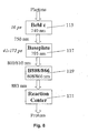
- the first sub-unit involved in light transduction is a lipid sack 101 containing bacteriochlorophyll (Bchl) c, which is organized in units of approximately 10,000 molecules that form rod-like structures 115 ( Fig. 7 ). As represented in the flow chart of Fig. 8 at 115, these molecules transduce photonic energy associated with 740 to 750 nm light in approximately 16 ps with very little loss. Photonic energy at 750 nm is then transduced at 117 by the baseplate membrane, which is comprised of approximately 500 molecules of Bchl a, to 795 nm to 800/810 mn in 41 - 175 ps.
- Bchl bacteriochlorophyll
- the B808/866 complex contains 10 - 20 Bchl a molecules, which absorb at 119 at 808 and 866 nm and transfer at 883 nm in approximately 250 ps.
- the last stage is where, at 121, a special pair of Bchl a molecules called the reaction center (RC) convert the light energy into chemical (photochemistry) to emit photons.
- RC reaction center
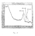
- Fig. 9 plots absorbance spectra data of isolated chlorosomes of C. aurantiacus noting peaks of interest. There, an absorbance peak at 740 - 750 nm attributable to the Bchl c rods 113 appears. A peak at 795 nm associated with the Bchl a baseplate is shown. In addition absorption of light in the blue region by the cartenoids is evident and blue secondary absorbance peaks from the Bchl c and a (designed as Soret peaks) occur. A peak attributable to the monemeric form of Bchl c (like its Soret) has a different absorbance wavelength peak than the oligomeric form that comprises the rods 113 in the chlorosomes. Like the Bchl a baseplate peak, the Bchl c oligomeric c peak is in the near infrared (NIR).
- NIR near infrared
- Intact C. aurantiacus bacteria display a unique adaptive ability to reversibly and enzymatically assemble and disassemble the foregoing structures to protect the organism from photo-induced damage.
- the spectral peaks of Fig. 9 are highly related to growth conditions of the whole cell C. aurantiacus bacteria.
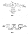
- An abbreviated form of the important basic mechanisms of energy transfer that occur between the molecules of the RC - chlorosome are as depicted in Fig. 10 .
- the carotenoids have been shown to also transfer energy to the Bchl c oligomeric rods as is true of the Soret band (a strong absorbance of a chlorophyll in the blue region of light).
- Soret band a strong absorbance of a chlorophyll in the blue region of light.
- the Bchl c found in C . aurantiacus chlorosomes are self-assembled (from monomeric form) into oligomeric rods. This results in a shift of the normal Soret (and Q y ) band into a redder form.
- the Bchl a found in the baseplate also has a Soret region in its photonic (blue) spectra. Carotenoids can begin to quench the structures ad should be closely watched, as this would cause the device of this invention to operate at lower efficiencies.
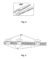
- the RC- chlorosomes were suspended in a liquid which was then applied to the hydrophobic surface of a borosilicate glass plate 118 as shown in Figs. 11 and 12 . It is the basis 102 of the chlorosomes 110 that adhere to the surface of the plate 118.
- the plate 118 is supported just above the surface of a glass slide or substrate 120.
- An epoxy seal 121 is formed about the edges of the plate 118.
- a commercially available silicon photovoltaic cell is supported on or closely spaced above the plate 118 . Illumination of the chlorosomes and the photovoltaic cell 125 by an LED 127 produces a voltage across the output of the photovoltaic cell 125 as can be observed by a multimeter 129.
- the SiPV was an Edmond Optics NT53-371 photovoltaic cell.
- Slide 120 was a Fischer microwells slide, part number 12-568-20 and the plate 118 was a Fischer cover glass, part number 12-541A.
- the microslide employed allowed for relatively straightforward application of the chlorosomes.
- This particular slide has two frosted rings on its surface, one of which is indicated at 131 in Fig. 11 .
- the frosted ring was just sufficiently high above the surface of the slide 120 that a drop of the liquid suspension containing the chlorosomes was retained.
- the cover glass 118 was rested on the ring 131 and when the suspending liquid had evaporated leaving the chlorosomes adherent to the hydrophobic borosilicate cover glass surface as shown, the epoxy seal 121 was applied.
- the microwells slide was useful in another respect. Having two of the frosted rings 131, it permitted for the side-by-side construction as illustrated in Fig. 11 and a control.
- the control could be an identical silicon photovoltaic cell illuminated through the slide 120 and a further glass 118 but absent the chlorosomes, or the control could be as illustrated in Fig. 11 but having the RC + chlorosomes entrapped.
- the chlorosomes and the light receiving surface of the photovoltaic cells were no more than a millimeter apart.
- the construction of the off-the-shelf photovoltaic cell placed the light receiving surface 133 of the silicon semiconductor in a metal housing or can 135 to be exposed through a glass closure 137.
- Table 1 Schematic Pictures of chlorosomes + Si PV Chlorosome Characteristics Size: 100x30x10 nm Approx Rh: 33 nm (calculated) 41 nm (DLS) Energy Transfer: Strokes Shift: 470-800/810 nm ⁇ : 320 nm QE: 69-92% QE Delay Time: 50 ps-1 ns Orientation Control: Yes Number of particles: 4x10 7 -8x10 9 chlorosomes Number of molecules: 4x10 15 -810 17
- the biological component (the chlorosomes), as well as controls, had to be isolated or purchased.
- several types of characterization had to be performed (and developed in some cases) so that the device fabrication could be accomplished. These involved many steps (and iterations) until sufficient materials were readily available (in the correct form) for use in the hybrid device configuration.
- C. aurantiacus cells were grown in 'D' media, under 6000 lux 50 °C in a one liter bottle ( Fig. 3.2 ).
- the 'D' mixture is as follows (all chemicals from Sigma): A mixture of 50.0 ml of the medium D stock is added to distilled water with 2.0 gm Difco Yeast Extract, 1.0 gm Glycylgylcine (freebase) adjusting the pH to 8.2. This mixture is then autoclaved for 0.5 hr at 450 °C.
- the medium D stock is prepared by mixing 40.0 ml of Nitch's Solution to 80.0 ml of the FeCl 3 solution in 3.5 1 of distilled water with the following traces: 8.0 gm Nitrilotriacetic acid, 4.8 gm of CaSO 4 • 2H 2 O, 8.0 gm MgSO 4 • 7H 2 O, 0.64 gm NaCl, 8.24 gm KNO 3 , 55.12 gm NaNO 3 , and 8.88 gm Na 2 HPO 4 .
- the Nitch's solution is made by placing 0.5 ml concentrated H 2 SO 4 , 2.28 gm MnSO 4 • H 2 O, 0.5 gm ZnSO 4 • 7H 2 O, 0.50 gm H 3 BO 3 , 0.025 gm CuSO 4 • 7H 2 O, 0.025 gm Na 2 MoO 4 • 2H 2 O, and 0.045 gm CoCl 2 • 6H 2 O into 1 liter of distilled water. This should be stored refrigerated.
- the FeCl 3 solution is prepared by adding 0.2905 gm of FeCl 3 (or 0.4842 gm FeCl 3 • 6H 2 O) to 1 liter distilled water and should also be refrigerated.
- Chlorosome isolation starts with cells are concentrated (600 ml) by centrifugation at 3,600 xg for 60 min. 2M NaSCN with 10 mM ascorbic acid in 10 mM Pi buffer (6.5 ml monobasic: 43.5 ml dibasic phosphate buffer per liter) was added to the weighed pellet in 4ml/gm amounts. Cells were homogenized 10x in a cell disruptor/homogenizer (Fisher Scientific).
- Disruption of cells was performed by (one) pass in a 4°C stored French Press (ThermoSpectronic) cell with 1.38 kbar (20,000 psi) DNAse I (Sigma) was added and the solution was incubated for 30 min at room temperature. The solution was passed through the cell two more times.
- the chlorosomes were (at various dilutions into Tris buffer) tested as in the above methods. This was performed in order to assess quality control by comparing spectral data (on absorbance) and relative output (emission).
- Another technique utilized the evaporation procedure as well as an aqueous method to allow incorporation of the chlorosomes onto a glass surface. Both techniques start with taking 0.5 ⁇ l of a known concentration of chlorosomes and placing it onto a borosilicate glass coverslip (Fisher Scientific). In the evaporation method, evaporation, under vacuum, is performed overnight and then the sample is sealed onto a fluorescent antibody microslide (Fisher Scientific). In the physical adsorption method, the slide is prepared in the aqueous phase and inverted during sealing, thus allowing for ensuring a hydrated sample as well as diffusion of the chlorosomes onto the surface of the hydrophobic glass. Samples were also studied under laser scanning confocal microscopy (LEICA) to investigate orientation and function (stability) was observed with absorbance spectroscopy of the sample afterwards.
- LEICA laser scanning confocal microscopy
- the engineering photonic devices had to be characterized. Using a modified NIST approach to calibrate the detectors, a system to develop sensitivity curves (to wavelength) was established. Each device was calibrated under similar conditions and intensities were varied to demonstrate intensity changes (if present) in the device. Finally, devices that were to be enhanced had to be selected. Known nonlinearities in traditional devices, such as the silicon PV's (or solar cells) were selected as optimal devices for enhancement.
- the counting and size information gathering was accomplished by several high-resolution microscopy techniques.
- Transmission Electron Microscopy (TEM) was performed by taking isolated chlorosomes and evaporating a 0.5 ⁇ l drop onto a bacitracin treated formvar coated grid (300 mesh). Negative stains of urinal acetate were used to enhance the images. Images were taken at the Life Science EM Facility at 25,000 x magnification. Images were saved in jpeg format, inserted into MATLAB and data (size and counts) were taken. Calculations were then scaled to predict how many chlorosomes were in a 1 ml sample for each of three dilutions. Absorbance spectroscopy of these dilutions was also performed to correlate absorbance spectra to count for the given population using a Beckman DU-65 photospectrometer (technique mentioned later).
- a final method was used to gather most of the counting data, namely, Field Emission Scanning Electron Microscopy (FESEM) at the Center for Solid State Electronics Research Center at Arizona State University on a Hitachi 4700 FESEM.
- FESEM Field Emission Scanning Electron Microscopy
- a hemocytometer technique was employed as an initial method that could be correlated to the others.
- Another technique used computer aided image processing to allow the chlorosomes surface to be assigned a '1' or 'white' pixel value and the background a '0' or 'black'. Accounting for surface area (number of pixels) per chlorosome, histograms were made and counts were calculated via computer.
- the final technique was a modified ASTM method in which the surface is transversed from left to right, and top to bottom, counting chlorosomes until 100 is reached. Then the number of pictures required to reach ⁇ 100 chlorosomes, the surface area of each picture, etc are accounted for and a final # chlorosomes/ml is calculated.
- five concentrations (plus a distilled water control) were imaged using all three techniques and counts were correlated to ABS spectra as well to aid in future calculations or determinations.
- the stubs were prepared by evaporating 100 ⁇ l of the dilution onto a hydrophobic borosilicate glass disk, attaching the disk to a stub via tape and carbon coating the samples for a period of 10 minutes.
- the chlorosomes were diluted with Tris buffer at pH 8.0 and 10 mM NaCl, by addition of 0.788 gm Trizma HCl into 500 ml of DI water, under constant stirring. Meanwhile, add 0.605 gm of Trizma Base was added into 500 ml of DI water under constant stirring. Both solutions were mixed together and 0.9 gm NaCl was added while mixture was stirred thus making 1 liter of 10 mM Trizma buffer, pH 8.0 with 20 mM NaCl.
- AFM Atomic Force Microscopy
- Ranges of dilutions were made by serial dilution of the stock chlorosome sample. Each dilution was placed into a standard cuvette (using a blank of Tris buffer) and full (400-900nm) absorbance readings were gathered (via an RS232C port) onto computer and analyzed and plotted in MATLAB. At this point, selection of a non-pigment wavelength (650nm in the case of the chlorosomes) was made to use in correlating absorbance to the previous counts made on each dilution and then plotted. This wavelength was selected for its non-photosynthetic (non-optically active) properties and consistent nature between different growth conditions during the counting experiments. Hence, a calibration curve was made between counting and absorbance for a series of dilutions of chlorosomes.
- the TEM images were placed into the Image Processing Toolbox for MATLAB for sizing measurements and calculations processing.
- the scalebar was measured (in the number of pixels across it to length) and then correlated to the size of the bar so a conversion could be made for length and width of chlorosomes.
- Imaging was performed within 36 hours of evaporation so that the chlorosomes would not swell (degrade). Images were taken and stored as jpeg format files and processed in MATLAB as with the other imaging techniques. Unusual formations or interactions at the surface were also imaged in the pictures. Placement of the concentrations required to make certain percent coverages into the microwells were done with an incubation time necessary for physical adsorption. The time was a predicted time based upon diffusion coefficient of the chlorosomes (as measured by DLS) and the path length. The final, assembled coverglass and microwells were sealed with a two-part epoxy and allowed to cure overnight.
- the first stability test for the isolated chlorosomes tested storage under two conditions.
- a 'fresh' sample was maintained for use in 7 °C freezer and a long-term (or later called 'frozen') sample was placed in liquid nitrogen (LN 2 ).
- Initial degradation was noted in the samples and can be clearly seen (at the monomeric 670 nm absorbance peak) in the absorbance spectra of the 'fresh' sample. Emission spectra were even gathered to see if a decrease in emission occurred.
- Degradation was quantified by noting a percent decrease in the 740nm absorbance. The samples were continuously illuminated and at specific time intervals, absorbance readings were taken. Degradation of the 740 Bchl c Q y band was measured by (1) peak height from start to finish and by (2) integration of the area under the Q y band. Times were marked when 5, 10, and 15% degradation of the peak were attained. A control sample (buffer) was also held under the same illumination and used as the blank in the photospectrometer.
- buffers (with a varying pH) were made from pH 2.0 to 12.0 and 1 ml of each was added to 1 ml of a chlorosome stock solution. Absorbance spectra as well as R h were measured for each sample. The R h was measured by testing 20 ⁇ l of the sample in the DLS system.
- Heat (or temperature) induced photodegradation or denaturation was also explored and tested. Starting at room temperature, a water bath holding a vial of chlorosomes was brought to near boiling over a period of hours. During the experiment, absorbance readings were taken at about every 5-10 °C and degradation was calculated as mentioned previously.
- a final experiment to show another mode of destruction of photo-stability was the addition of a competitor (for absorbance of blue light).
- Carotenoid solutions from the isolation procedure were reintroduced into the chlorosome sample (by dilution) and emission measurements were taken.
- Side control experiments were performed by addition of buffer alone. Stimulation was made by the RF-1501 Shimadzu spectrofluorometer and emission was measured on a photodiode after passage through an 800 nm interference filter (so that scatter and excitation energies could be removed). This also allowed for ratios of the Bchl c to a, Soret, and carotenoid peak to be calculated and compared for potential enhancement calculations for the hybrid well experiments.
- the initial step in manufacture of the hybrid wells is the chlorosomes (or controls) themselves.
- the biophotonic hybrid device had to then be assembled, using the various interfacing techniques to integrate the chlorosomes (and controls), in a controlled, patterned array with the silicon (Si) photovoltaic (PV) photocell.
- the device parameters or specifications had to be tested. These include: maximum output, time-response (or rise time), spectral sensitivity, intensity sensitivity, temperature sensitivity, and device lifetime.
- the device was fabricated by utilizing physical adsorption immobilization to interface chlorosomes (on a glass substrate/microslide with well) to the Si PV photocell.
- the components were interfaced (mechanically) by a self-built optical chamber made from acrylic sheet.
- the microslide port was milled into one piece, holes were drilled for the fiber optic bundle and the Si PV detector. Accessory ports/chambers were made to fit 25 mm filters such as additive (or subtractive) and NDF for wavelength and intensity control, respectively.
- the whole apparatus was black felted to reduce external light leakage. Power was supplied using a standard variable power supply (for the LED) and the Si PV was monitored utilizing a digital multimeter (DMM).
- DDMM digital multimeter
- the devices (ranging from low to high percent coverages) were tested under LED illumination and ratios were made to the same detector under the same illumination (minus the hybrid wells) and percentages have been calculated. This percent enhancement signifies when a hybrid well device increases the measured output (and by how much percent) over the stand-alone configuration.
- the rise time (the time it takes to get from 10% to 90% final voltage) was measured and compared between the hybrid well devices to the stand-alone detector. This was accomplished with a stopwatch and DMM.
- White light LED visible light
- White LED's were implemented into the device apparatus and run at a few intensities and on Si PV as well as Si TP.
- Device enhancement was not further enhanced by the addition of the full spectra light, in fact, red band quenching might have been recorded as noted by others (Klar, 2000) in other systems and setups.
- monochromatic light as the stimulation source intensities were run at different levels sufficient for device detection but lower than saturation (of device or hybrid component). Again, full range of percent coverages were evaluated and replicates run. Again, the detector's response (without the hybrid layer) was used as a point of reference in determining percent enhancement.
- C. aurantiacus is self-adapting. This meant that chlorosomes taken from the same growth of cells could not be relied upon to behave consistently.
- Stimulation time must also be accounted for since the time of stimulation and intensity will correlate to a certain photostress that the device can handle before irreversible damage is done to the biohybrid layer.
- a controlled environment for validation purposes is also necessary (a dark room or constant intensity area), as well as selection of an appropriate measuring device, such as a high impedance digital multimeter (DMM) for photovoltaic devices for example.
- DDM digital multimeter
- Processing of the chlorosome requires isolation of the chlorosomes from the whole cell walls. This is done using a procedure well documented although certain factors do arise in the process. There are different procedures used to isolate chlorosomes without the reaction centers (RC-) versus those with (RC+). The solvents, agents, and buffer types used in the procedure are also very important and factors such as (the type, molarity, ionic strength, pH, and strength) all come into play. These factors will affect the state of aggregation and purity (and success) of the isolated chlorosomes.
- Manufacture of the chlorosome layer is the step whereby means of immobilization (namely physical adsorption) a monolayer (or percent thereof) is deposited onto the surface of a substrate (borosilicate glass).
- a substrate borosilicate glass.
- Important factors for successful devices include: the fabrication conditions (temperature, incubation time, Light ON/OFF, and in the laminar flow hood); sealing method; concentration, volume, and % coverage (and hence interparticle distances); droplet placement (on the coverslip or in the well); and coverslip hydrophobicity, which all relate to chlorosome orientation (facing Si PV or LED).
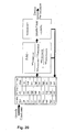
- a multiple input, multiple output environmental chamber 150 (MIMO/EC) was constructed as diagrammed in Fig. 22 .
- FIG. 23 illustrates an environmental chamber of this kind. On its door 170 multiple shelves 172 are supported and have openings to retain culture-containing rest tubes or containers. Vertical dividers 174 separate the compartments 155 - 163. Horizontal dividers 176 separate the compartments vertically. Light bulbs, one of which is shown at 177 provide illumination. A series of fans 179 regulate temperature.
- the DOE technique allows for correlation of data statistically easier than OFAT or best-guess approaches. It reduces the total number of experiments, allows for a good, thought experimental design. It allows for error to be quantified and it can distinguish if factors have any to no effect or if interaction among factors occurs.
- the response, the output under study was concentration (by absorbent spectroscopy) after three days' growth.
- a factorial design was chosen to quantify the relative importance of interaction between light intensity, temperature, and volume of media.
- the approach used was Design of Experiments (DOE). This method allows for data to be gathered in a way to avoid error by establishing an experiment protocol and quantify error in a mathematical way.
- the regression method that was used was the analysis of variance (ANOVA) technique. This tool (DOE) allows for data to be gathered at normal conditions (centerpoint) and at extremes (above and below the centerpoint). Analysis is based on quantifying effect and probability of effect of a factor or interaction on the output variable.
- the cell culture stock was prepared for testing as in [1] and the MIMO/EC DOE culture incubation apparatus was also used.
- the data was gathered from nine strands that all came from a centerpoint grown stock (cultured at the centerpoint for 14 days).
- the data was gathered (randomly) at the end of a three-day growth cycle period and placed into the Stat-EaseTM software for analysis. Three replicates at each corner were taken as well as five centerpoint readings.
- the pigment protein content was deduced by taking absorbance spectra from 650nm to 900nm on each sample. This was done with a Beckman DU-65 photospectrometer. Then a ratio (R 1 ) was calculated by dividing the absorbance at 740nm by that at 808nm. Then another ratio (R 2 ) was calculated with the 740 over 866nm peak absorbance readings. In this experiment, pigment protein content was desired to see an increase (larger chlorosomes).
- the DOE approach used involves seven steps in order to perform the experiment.
- the next step is to identify the output variable(s) to be studied. Since the change in pigment protein content was desired to be analyzed, the ratios of the 740 to 808 and 740 to 866 nm peak absorbances were chosen. The ratios were designated with a R 1 for the 740/808 and a R 2 for the 740/866 ratio. Since the choice of factors and levels were as stated, a 2 3 factorial approach was chosen. In this approach, three replicates and five centerpoints were chosen also. The experiment was run at the end of a three day growth period and data was gathered in a random fashion. Since replicates were used the data analysis will not include determination normal % distribution plot and the analysis will really be based on the ANOVA tables. Interaction between factors was determined from the ANOVA as well as the interaction graphs provided by the software. Finally conclusions must be made based on the analysis and results.
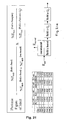
- the R 1 ratio developed strong effects due to each individual factor and the interaction between Temperature and %Volume. All other interactions were insignificant when compared to these four factors/interaction. This can be seen in the ANOVA table in Table 4.
- the normal % probability plot and interaction plot (between Temp and %Vol) can be found in Figs. 11 , 13a and 13b . Based on the analysis, the highest level for the R 1 ratio would be with bacteria grown under the following conditions: low temperature, low light intensity, and high %volume. TABLE 4.
- the R 2 ratio developed strong effects due to only temperature and no interactions. All other factors and interactions were insignificant when compared to temperature (see Table 5).
- the normal % probability plot and interaction plot (between Temp and %Vol) can be found in Figs. 13a and 13b . As shown in Fig. 14a , the results are so close to the linear line that they are deemed insignificant except for temperature. Even the interaction plots ( Fig. 14b ) showed slight interactions. Note how the lines cross but the error bars overlap so that these lines could in fact be parallel and therefore non-interacting. The highest level possible for the R 2 ratio would be with bacteria grown under low temperature. TABLE 5. ANOVA Table for experiment of R 2 ratio. Note DF represents degrees of freedom.
- R 1 and R 2 are not dependent upon the same factors.
- R 1 is sensitive to temperature, light intensity, and % volume and the interaction of temperature and % volume.
- the R 2 ratio is dependent upon only the temperature during growth. This ratio was long believed to be only dependent upon light intensity but temperature was more significant. This may be due to the fact that the real dependent output is the R 1 ratio. If the bacteria are grown under those conditions and R 1 changes, R 2 must change as well but not vice-versa.
- the light intensity and the light-temperature interaction factors had coefficients of only one half the temperature factor in the 740 nm variable. This contrast was particularly apparent in those response variables that do not have photosynthetic activity. There is clearly a correlation between the light factor, the light and temperature interaction, and the absorbance of Bchl c (740 nm). Since the other response variables are mostly dependent on temperature, their changes can be primarily attributed to the change in absorbance which results from increased and/or decreased concentration of cells. Because cellular membrane components have an absorbance of 650-700 nm, the concentration of cells in each sample can be determined from the absorbance data in this region. By normalizing the data, it is possible to extrapolate the Bchl c absorbance for individual cells. This is the next logical step in analyzing the data.
- a method was developed to establish a faster process to count whole cells.
- a modified hemocytometry counting technique was used to count whole cell C .
- aurantiacus concentrations per unit length of 10 ⁇ m
- absorbance data was gathered as three replicates of: 1:1, 1:1.1, 1:1.5, 1:2, 1:3, 1:4, 1:5, 1:10, and 1:50 dilutions were made.
- Full spectra (absorbance) data was gathered for each dilution, as in Fig. 15a .
- Each replicate was run to minimize instrument and operator error, Fig. 15b and peak data was gathered and averaged at 650, 740, 808, and 866 nm.
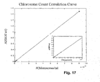
- determining the quantity of chlorosomes coating the cover glass hydrophobic surface was important. Absorbance of light was correlated to the density of chlorosomes as illustrated in Fig. 17 .
- the calibration plot of Fig. 17 plots chlorosome count against chlorosome absorbance at the 650 nm wavelength.
- the 650 nm wavelength is chosen rather than a wavelength where absorbance of the chlorosome exhibits a peak because the absorbance at those wavelengths exhibiting a peak in the absorbance spectrum vary from one chlorosome to another depending, inter alia, on environmental factors effecting the growth of the bacterium from which the chlorosome was taken.
- the 650 nm wavelength absorbance then, is linearly related to chlorosome count and not another variable.
- chlorosome percent coverage of the SiPV's light receiving surface is important as demonstrated by the Fig. 19 plot of percent enhancement against percent coverage. Ideally, in this particular embodiment at least, coverage should be in the 4 to 7% range and preferably about 4%.
- Fig. 1 is a conceptual block diagram that indicates the design and development of a hybrid device of the nature of the enhanced photovoltaic cell described above. At each stage of development multiple variables entered the design process. This is tabulated, as well, in Table 2. From this it will be seen that a robust program such as the design of experiments program that permits the assessment of multiple variables and their interaction is an enabling design tool in arriving at a final product that meets the objectives of high performance, robustness, scalability, energy interactivity and adaptability.
- the device needs to be tested using an appropriate light source and wavelength, such as a 470 nm LED or an incandescent light bulb with a correct interference filter yielding 470 nm wavelength. Intensity is a variable.
- suitable light waveguides or fiber optics may be a variable to consider. Stimulation time must be taken into account since it and intensity will correlate to a certain photostress that the device will be able to handle or not handle if irreversible damage is to be avoided. Controlled environments and appropriate measurement devices are to be chosen.
- Processing of the chlorosome requires isolation of the chlorosomes from the whole cells. As indicated above, this is done using procedures well documented. Nevertheless certain factors need to be taken into account during this process. These are the different procedures used to isolate chlorosomes without the reaction centers (i.e. the RC - chlorosomes vs. the RC + chlorosomes). Solvents, agents and buffer types used in the procedure are also important, and factors such as the type, molarity, ionic strength, PH and strength of these all come into play. These factors will affect the state of aggregation impurity of the isolated chlorosomess, and consequently the ultimate success of the design.
- Manufacture of the chlorosomes layer is the step whereby means of immobilization (which is to say physical absorption) of a monolayer (or a percent of a monolayer) is deposited onto the surface of the substrate such as the borosilicate glass.
- important factors for successful devices include the fabrication conditions of temperature, incubation time, lighting (on or off) and operation of a laminar flow hood. Sealing method, concentration volume and percentage of coverage enhance interpartical distances, dropment placement on the cover slip or in the well, and cover slip hydrophobisity all bear on chlorosome placement and orientation (i.e. either facing the SiPV or the LED in the preceding exemplary arrangements).
- Figure of Merit (FoM) is a concept employed widely and in many disciplines, although ordinarily not where biological matters arise.
- a biophotonic Figure of Merit was devised to quantify chlorosome performance.
- This FoM takes into account the total transmittance of the Bchl c Soret at 440 nm as compared to the total Soret and corrotenoid 460 nm transmittance and the baseplate Bchl a transmittance at 795 nm as compared to the Bchl c oligomeric transmission at 740 nm.
Landscapes
- Health & Medical Sciences (AREA)
- Physics & Mathematics (AREA)
- Chemical & Material Sciences (AREA)
- General Health & Medical Sciences (AREA)
- Spectroscopy & Molecular Physics (AREA)
- Analytical Chemistry (AREA)
- General Physics & Mathematics (AREA)
- Biochemistry (AREA)
- Life Sciences & Earth Sciences (AREA)
- Immunology (AREA)
- Pathology (AREA)
- Hematology (AREA)
- Clinical Laboratory Science (AREA)
- Chemical Kinetics & Catalysis (AREA)
- Apparatus Associated With Microorganisms And Enzymes (AREA)
- Measuring Or Testing Involving Enzymes Or Micro-Organisms (AREA)
- Investigating Or Analysing Materials By Optical Means (AREA)
Claims (28)
- Hybrides lichtempfindliches Gerät umfassend:(a) einen lichtempfindlichen Halbleiter (125);
dadurch gekennzeichnet, dass(b) eine Vielzahl von Chlorosomen (100-104, 110) gehalten wird in einer Lichtkontaktbeziehung mit einer lichtempfangenden Oberfläche (133) des lichtempfindlichen Halbleiters (125), sodass von den Chlorosomen (100-104, 110) abgegebenes Licht von dem lichtempfindlichen Halbleiter (125) empfangen wird,(c) die Chlorosomen (100-104, 110) an einer transparenten Platte (118) anhaften, die über einer lichtempfangenden Oberfläche (133) des lichtempfindlichen Halbleiters (125) liegt,(d) die Chlorosomen (100-104, 110) an einer hydrophoben Oberfläche der transparenten Platte (118) anhaften, und(e) die Platte eine Borosilikatplatte ist. - Hybrides lichtempfindliches Gerät gemäß Anspruch 1, wobei die Chlorosomen (100-104, 110) einen cytoplasmatischen Membransack (101) von lichtempfindlichen Molekularstrukturen (115) und eine Basisplatte (102) aufweisen, wobei mindestens eine substantielle Anzahl von Chlorosomen (100-104, 110) mit Ihrer Basisplatte (102) dem lichtempfindlichen Halbleiter (125) zugewandt und mit ihrem cytoplasmatischen Membransack (101) von dem lichtempfindlichen Halbleiter (125) abgewandt ausgerichtet ist.
- Hybrides lichtempfindliches Gerät gemäß Anspruch 1, wobei der lichtempfindliche Halbleiter (125) eine Lichtreaktion hat, die bei einem ersten Bereich von Lichtwellenlängen verringert ist, und die Chlorosomen (100-104, 110) eine Lichtreaktion haben, die bei einem zweiten Bereich von Lichtwellenlängen vergrößert ist, der mindestens teilweise mit dem ersten Bereich von Lichtwellenlängen zusammenfällt, und eine Emission in der Richtung des lichtempfindlichen Halbleiters (125) von Licht außerhalb des ersten Bereichs von Lichtwellenlängen.
- Hybrides lichtempfindliches Gerät gemäß Anspruch 3, wobei der lichtempfindliche Halbleiter (125) eine Siliziumphotozelle (125) ist.
- Hybrides lichtempfindliches Gerät gemäß Anspruch 1, wobei mindestens eine Mehrzahl der Chlorosomen (100-104, 110) in einer lichtabgebenden Richtung zu dem lichtempfindlichen Halbleiter (125) ausgerichtet ist.
- Hybrides lichtempfindliches Gerät gemäß entweder Anspruch 1 oder 2, wobei die Chlorosomen (110-104, 110) Chlorosomen von C. aurantiacus sind.
- Hybrides lichtempfindliches Gerät gemäß Anspruch 6, wobei die Chlorosomen (100-104, 110) RC- Chlorosomen von C. aurantiacus sind.
- Hybrides lichtempfindliches Gerät gemäß Anspruch 2, wobei die Chlorosomen-Basisplatte (102) einer lichtempfangenden Oberfläche (133) des lichtempfindlichen Halbleiters (125) benachbart ist.
- Hybrides lichtempfindliches Gerät gemäß Anspruch 2, wobei die Chlorosomen-Basisplatten (102) in einem geringen Abstand von dem lichtempfindlichen Halbleiter (125) beabstandet sind.
- Hybrides lichtempfindliches Gerät gemäß Anspruch 3, wobei die verringerte Antwort des lichtempfindlichen Halbleiters (125) in einem blauen Bereich des sichtbaren Spektrums liegt und die Chlorosomen (100-104, 110) auf Licht darin in dem blauen Bereich des sichtbaren Spektrums ansprechen durch Emission von Licht außerhalb des blauen Bereichs.
- Hybrides lichtempfindliches Gerät gemäß Anspruch 10, wobei das Licht, das von den Chlorosomen (100-104, 110) emittiert wird, Licht im 800nm-Nahinfrarotbereich des sichtbaren Spektrums ist.
- Verfahren zur Herstellung eines hybriden lichtempfindlichen Geräts einschließlich:(a) Bereitstellen von photosynthetischen, Chlorosomen enthaltenden Bakterien,(b) Extrahieren der Chlorosomen (100-104, 110) aus den Bakterien,(c) Bereitstellen eines lichtempfindlichen Halbleiters (125), und(d) Anordnen der Chlorosomen (100-104, 110) nahe einer lichtempfangenden Oberfläche (133) des lichtempfindlichen Halbleiters (125),(e) wobei der Schritt (d) das Bereitstellen einer transparenten Platte (118), das Befestigen der Chlorosomen (100-104, 110) an der transparenten Platte (118), und das Positionieren der transparenten Platte (118) über der lichtempfangenden Oberfläche (133) des lichtempfindlichen Halbleiters (125) liegend umfasst,(f) wobei das Bereitstellen der transparenten Platte (118) weiterhin das Bereitstellen einer transparenten Platte (118) mit einer hydrophoben Oberfläche umfasst und das Befestigen der Chlorosomen (100-104, 110) weiterhin das Befestigen der Chlorosomen an der hydrophoben Oberfläche einschließt,(g) wobei das Bereitstellen der transparenten Platte (118) das Bereitstellen einer Borosilikatplatte (118) umfasst.
- Verfahren gemäß Anspruch 12, wobei der Schritt (d) das Ausrichten von mindestens der Mehrzahl der Chlorosomen (100-104, 110) in einer Lichtabgaberichtung in Richtung des lichtempfindlichen Halbleiters (125) umfasst.
- Verfahren gemäß Anspruch 12, wobei die Chlorosomen einen cytoplasmatischen Membransack (101) von lichtempfindlichen Molekularstrukturen und eine Basisplatte (102) aufweisen, und der Schritt (d) das Ausrichten von mindestens einer substantiellen Anzahl der Chlorosomen mit ihren Basisplatten (102) dem lichtempfindlichen Halbleiter (125) zugewandt und ihrem cytoplasmatischen Sack (101) von dem lichtempfindlichen Halbleiter (125) abgewandt umfasst.
- Verfahren gemäß Anspruch 12, wobei der Schritt (a) die Bereitstellung von C. aurantiacus umfasst.
- Verfahren gemäß Anspruch 15, wobei der Schritt (b) das Extrahieren der RC- Chlorosomen von C. aurantiacus umfasst.
- Verfahren gemäß Anspruch 13, wobei der Schritt (d) das Anordnen der Chlorosomen (100-104, 110) angrenzend an eine lichtempfangende Oberfläche (133) des lichtempfindlichen Halbleiters (125) umfasst.
- Verfahren gemäß Anspruch 14, wobei der Schritt (d) das Anordnen der Chlorosomen (100-104, 110) mit ihren Basisplatten (102) angrenzend an eine lichtempfangende Oberfläche (133) des lichtempfindlichen Halbleiters (125) umfasst.
- Verfahren gemäß Anspruch 14, wobei der Schritt (d) das Anordnen der Chlorosomen (100-104, 110) beabstandet zu und angrenzend an die lichtempfangende Oberfläche (133) des lichtempfindlichen Halbleiters (125) umfasst.
- Verfahren gemäß Anspruch 12, wobei der Schritt (c) das Bereitstellen eines lichtempfindlichen Halbleiters (125) umfasst mit einer Lichtantwort, die bei einem ersten Bereich von Wellenlängen verringert ist, und der Schritt (a) die Auswahl von Chlorosomen (100-104, 110) umfasst, die eine Lichtantwort haben, die bei einem zweiten Bereich von Wellenlängen vergrößert ist, der mindestens teilweise mit dem ersten Bereich von Wellenlängen zusammenfällt und einer Lichtemission außerhalb des ersten Bereichs von Lichtwellenlängen.
- Verfahren gemäß Anspruch 20, wobei die Auswahl eines Chlorosoms (100-104, 110) die Kraftanpassung von Bakterien mit Chlorosomen in der Weise umfasst, um eine Modifikation einer Transferfunktion zu bewirken, die ihre Ausgaben unter bestimmten Eingaben regelt, wobei die Kraftanpassung so bewerkstelligt wird, dass die Lichtantwort bei dem zweiten Bereich von Lichtwellenlängen vergrößert ist und die Lichtemission außerhalb des ersten Bereichs liegt.
- Verfahren gemäß Anspruch 21, wobei die Kraftanpassung die Entwicklung von Versuchsbestimmungen von Umgebungsfaktoren umfasst, die eine Anpassung von Bakterien erzwingen auf der Grundlage von mehreren Umgebungsvariablen, denen Probenbakterien ausgesetzt werden.
- Verfahren gemäß Anspruch 22, wobei die Probenbakterien derselben Art angehören.
- Verfahren gemäß Anspruch 22, wobei die Probenbakterien C. aurantiacus sind.
- Verfahren gemäß Anspruch 22, wobei die Kraftanpassung die Berechnung eines Bewertungsfaktors für die Chlorosomen (100-104, 110) der Bakterien und die Identifizierung der Umgebungsfaktoren umfasst, die zu einem akzeptablen Bewertungsmaßstab führen.
- Verfahren gemäß Anspruch 25, wobei der Bewertungsmaßstab ist:

- Verfahren gemäß Anspruch 20, wobei die verringerte Antwort des lichtempfindlichen Halbleiters (125) in dem blauen Bereich des sichtbaren Spektrums liegt und die Kraftanpassung der Bakterien die Kraftanpassung der Bakterien umfasst, sodass die Chlorosomen (100-104, 110) auf Licht ansprechen in dem blauen Bereich, um Licht abzugeben außerhalb des blauen Bereichs.
- Verfahren gemäß Anspruch 27, wobei das Licht, das von den Chlorosomen (100-104, 110) abgegeben wird, Licht in dem Nahinfrarotbereich des sichtbaren Spektrums ist.
Applications Claiming Priority (3)
| Application Number | Priority Date | Filing Date | Title |
|---|---|---|---|
| US40877502P | 2002-09-07 | 2002-09-07 | |
| US408775P | 2002-09-07 | ||
| PCT/US2003/028052 WO2004023099A2 (en) | 2002-09-07 | 2003-09-08 | Nanoengineered biophotonic hybrid device |
Publications (3)
| Publication Number | Publication Date |
|---|---|
| EP1546320A2 EP1546320A2 (de) | 2005-06-29 |
| EP1546320A4 EP1546320A4 (de) | 2010-08-11 |
| EP1546320B1 true EP1546320B1 (de) | 2015-08-26 |
Family
ID=31978675
Family Applications (1)
| Application Number | Title | Priority Date | Filing Date |
|---|---|---|---|
| EP03794664.7A Expired - Lifetime EP1546320B1 (de) | 2002-09-07 | 2003-09-08 | Im nanomassstab konstruierte biophotonische hybridvorrichtung |
Country Status (4)
| Country | Link |
|---|---|
| US (4) | US7067293B2 (de) |
| EP (1) | EP1546320B1 (de) |
| AU (1) | AU2003263106A1 (de) |
| WO (1) | WO2004023099A2 (de) |
Families Citing this family (8)
| Publication number | Priority date | Publication date | Assignee | Title |
|---|---|---|---|---|
| US9034623B2 (en) | 2002-09-07 | 2015-05-19 | Jeffrey T. LaBelle | Nanoengineered biophotonic hybrid device |
| US8754322B2 (en) * | 2006-11-03 | 2014-06-17 | Empire Technology Development, Llc | Harvesting and aggregating low photonic energy |
| WO2015188107A1 (en) | 2014-06-06 | 2015-12-10 | Arizona Board of Regents of behalf of Arizona State University | Unique self-assembled poly-amidoamine polymers and their electrochemical reactivity |
| WO2016133706A1 (en) | 2015-02-16 | 2016-08-25 | Arizona Board of Regents of behalf of Arizona State University | Biology-based enhanced vision using light amplification and adaptable to thin films |
| WO2018067626A1 (en) | 2016-10-04 | 2018-04-12 | Arizona Board Of Regents On Behalf Of Arizona State University | Flexible sensors incorporating piezoresistive composite materials and fabrication methods |
| WO2018175448A1 (en) | 2017-03-20 | 2018-09-27 | Arizona Board Of Regents On Behalf Of Arizona State University | Analyte detection using electrochemical impedance spectroscopy-based imaginary impedance measurement |
| US10229092B2 (en) | 2017-08-14 | 2019-03-12 | City University Of Hong Kong | Systems and methods for robust low-rank matrix approximation |
| CN109576208B (zh) * | 2018-10-16 | 2022-03-29 | 中子康(武汉)医药科技有限公司 | 利用光合成反应增加生物分子量子能量共性技术的应用 |
Citations (1)
| Publication number | Priority date | Publication date | Assignee | Title |
|---|---|---|---|---|
| US4051374A (en) * | 1976-06-04 | 1977-09-27 | Eastman Kodak Company | Imaging device having improved blue response |
Family Cites Families (16)
| Publication number | Priority date | Publication date | Assignee | Title |
|---|---|---|---|---|
| US3935031A (en) * | 1973-05-07 | 1976-01-27 | New England Institute, Inc. | Photovoltaic cell with enhanced power output |
| US4103064A (en) * | 1976-01-09 | 1978-07-25 | Dios, Inc. | Microdevice substrate and method for making micropattern devices |
| US4190950A (en) * | 1977-06-01 | 1980-03-04 | The United States Of America As Represented By The Department Of Energy | Dye-sensitized solar cells |
| US4149902A (en) * | 1977-07-27 | 1979-04-17 | Eastman Kodak Company | Fluorescent solar energy concentrator |
| US5326692B1 (en) * | 1992-05-13 | 1996-04-30 | Molecular Probes Inc | Fluorescent microparticles with controllable enhanced stokes shift |
| DE4208645A1 (de) * | 1992-03-18 | 1993-09-23 | Bayer Ag | Optischer festphasenbiosensor auf basis fluoreszenzfarbstoffmarkierter polyionischer schichten |
| US5504573A (en) * | 1993-10-13 | 1996-04-02 | Man-Gill Chemical Company | Apparatus and method for analyzing particles deposited on a substrate using substantially continuous profile data |
| FR2719602B1 (fr) * | 1994-05-05 | 1996-07-26 | Biocom Sa | Procédé et installation pour la numérisation de cellules et micro-organismes, notamment des produits alimentaires ou des fluides biologiques. |
| US5466301A (en) * | 1994-06-29 | 1995-11-14 | Texas Instruments Incorporated | Solar cell having an output-increasing, protective cover |
| US6342389B1 (en) * | 1995-04-10 | 2002-01-29 | Roger S. Cubicciotti | Modified phycobilisomes and uses therefore |
| FR2757635B1 (fr) * | 1996-12-24 | 1999-02-05 | Oreal | Procede d'evaluation des dommages induits dans la peau par les uv-a |
| US6342398B1 (en) * | 1998-12-17 | 2002-01-29 | Taiwan Semiconductor Manufacturing Company | Method of backside emission analysis for BGA packaged IC's |
| GB9905642D0 (en) | 1999-03-11 | 1999-05-05 | Imperial College | Light concentrator for PV cells |
| US6376312B1 (en) * | 2001-03-26 | 2002-04-23 | Advanced Micro Devices, Inc. | Formation of non-volatile memory device comprised of an array of vertical field effect transistor structures |
| US6603069B1 (en) * | 2001-09-18 | 2003-08-05 | Ut-Battelle, Llc | Adaptive, full-spectrum solar energy system |
| US6538191B1 (en) * | 2001-09-26 | 2003-03-25 | Biomed Solutions, Llc | Photocell with fluorescent conversion layer |
-
2003
- 2003-09-08 EP EP03794664.7A patent/EP1546320B1/de not_active Expired - Lifetime
- 2003-09-08 US US10/658,541 patent/US7067293B2/en not_active Expired - Fee Related
- 2003-09-08 WO PCT/US2003/028052 patent/WO2004023099A2/en not_active Ceased
- 2003-09-08 AU AU2003263106A patent/AU2003263106A1/en not_active Abandoned
-
2006
- 2006-06-26 US US11/475,343 patent/US20100233749A1/en not_active Abandoned
- 2006-06-26 US US11/475,338 patent/US20100233748A1/en not_active Abandoned
- 2006-06-26 US US11/475,356 patent/US20100240020A1/en not_active Abandoned
Patent Citations (1)
| Publication number | Priority date | Publication date | Assignee | Title |
|---|---|---|---|---|
| US4051374A (en) * | 1976-06-04 | 1977-09-27 | Eastman Kodak Company | Imaging device having improved blue response |
Non-Patent Citations (2)
| Title |
|---|
| DONATELLA CARBONERA ET AL: "Fluorescence and Absorption Detected Magnetic Resonance of Chlorosomes from Green BacteriaChlorobium tepidumandChloroflexus aurantiacus. A Comparative Study", THE JOURNAL OF PHYSICAL CHEMISTRY B, 1 January 2001 (2001-01-01), pages 246 - 255, XP055092084, Retrieved from the Internet <URL:http://pubs.acs.org/doi/pdf/10.1021/jp001778+> DOI: 10.1021/jp001778+ * |
| YOSHITAKA SAGA ET AL: "Fluorescence Emission Spectroscopy of Single Light-Harvesting Complex from Green Filamentous Photosynthetic Bacteria", THE JOURNAL OF PHYSICAL CHEMISTRY B, vol. 106, no. 6, 1 February 2002 (2002-02-01), pages 1430 - 1433, XP055092016, ISSN: 1520-6106, DOI: 10.1021/jp0138227 * |
Also Published As
| Publication number | Publication date |
|---|---|
| AU2003263106A1 (en) | 2004-03-29 |
| WO2004023099A3 (en) | 2005-04-21 |
| US7067293B2 (en) | 2006-06-27 |
| EP1546320A2 (de) | 2005-06-29 |
| AU2003263106A8 (en) | 2004-03-29 |
| WO2004023099A2 (en) | 2004-03-18 |
| US20060008893A1 (en) | 2006-01-12 |
| US20100233748A1 (en) | 2010-09-16 |
| US20100240020A1 (en) | 2010-09-23 |
| EP1546320A4 (de) | 2010-08-11 |
| US20100233749A1 (en) | 2010-09-16 |
Similar Documents
| Publication | Publication Date | Title |
|---|---|---|
| EP2059810B1 (de) | System zur erkennung und quantifizierung biologischer materie aus einem oder mehreren optischen sensoren und einer oder mehreren lichtquellen, entsprechendes verfahren und anwendungen dafür | |
| EP1546320B1 (de) | Im nanomassstab konstruierte biophotonische hybridvorrichtung | |
| US8173407B2 (en) | Nanoengineered biophotonic hybrid device | |
| Koc et al. | Characterizing photon reabsorption in quantum dot-polymer composites for use as displacement sensors | |
| US7515269B1 (en) | Surface-enhanced-spectroscopic detection of optically trapped particulate | |
| Villar et al. | Raman spectroscopic and scanning electron microscopic analysis of a novel biological colonisation of volcanic rocks | |
| Aghlmand et al. | A 65-nm CMOS fluorescence sensor for dynamic monitoring of living cells | |
| EP4127664B1 (de) | Verfahren zur charakterisierung von mikroorganismen mittels transmissionsbildgebung | |
| Nelson et al. | Handheld fluorometers for lab-on-a-chip applications | |
| US9865827B1 (en) | Adaptively optimized biological components for biohybrid devices | |
| CN101281124B (zh) | 宽带腔增强吸收光谱大气环境光电监测系统 | |
| US9034623B2 (en) | Nanoengineered biophotonic hybrid device | |
| US9614009B2 (en) | Organic p-n junction based ultraviolet detection device and ultraviolet image detector using same | |
| WO2007065423A1 (de) | Verfahren und vorrichtung zur detektion von mikroorganismen und/oder deren aktivität | |
| DE102005018337A1 (de) | Mikrooptisches Detektionssystem und Verfahren zur Bestimmung temperaturabhängiger Parameter von Analyten | |
| Tamamizu et al. | Sunscreen redox status in a multicellular cyanobacterium visualized by Raman scattering spectral microscope | |
| US20230332955A1 (en) | Device and Method for Color Identification Using Multiple 2D Material Filters | |
| Luo | Transition-metal ions in II-VI semiconductors: zinc selenide and zinc telluride | |
| WO2024238038A1 (en) | Matched optical filter | |
| LaBelle | Design feasibility of a nanoscale biophotonic hybrid device | |
| Lovecchio et al. | A thin film-based lab-on-chip for in-field analysis in agriculture | |
| KOTTAHACHCHIGE et al. | Development of filterless, miniaturized fluorescence detection system | |
| Abernathy | Environmental causes of pigment heterogeneity in phytoplankton species | |
| Shin | LED-Based Optical Sensing Platforms for Multi-Analyte Detection | |
| Connor | Investigating the use of fast repetition rate fluorometry in understanding algal physiology in optically complex oceans |
Legal Events
| Date | Code | Title | Description |
|---|---|---|---|
| PUAI | Public reference made under article 153(3) epc to a published international application that has entered the european phase |
Free format text: ORIGINAL CODE: 0009012 |
|
| 17P | Request for examination filed |
Effective date: 20050407 |
|
| AK | Designated contracting states |
Kind code of ref document: A2 Designated state(s): AT BE BG CH CY CZ DE DK EE ES FI FR GB GR HU IE IT LI LU MC NL PT RO SE SI SK TR |
|
| AX | Request for extension of the european patent |
Extension state: AL LT LV MK |
|
| DAX | Request for extension of the european patent (deleted) | ||
| RAP1 | Party data changed (applicant data changed or rights of an application transferred) |
Owner name: LABELLE, JEFFREY, T. Owner name: PIZZICONI, VINCENT, B. |
|
| RIN1 | Information on inventor provided before grant (corrected) |
Inventor name: PIZZICONI, VINCENT, B. Inventor name: LABELLE, JEFFREY, T. |
|
| A4 | Supplementary search report drawn up and despatched |
Effective date: 20100714 |
|
| RIC1 | Information provided on ipc code assigned before grant |
Ipc: H01L 31/00 20060101ALI20100708BHEP Ipc: C12N 13/00 20060101AFI20050426BHEP Ipc: C12M 1/36 20060101ALI20100708BHEP Ipc: C12N 11/14 20060101ALI20100708BHEP |
|
| 17Q | First examination report despatched |
Effective date: 20120323 |
|
| GRAP | Despatch of communication of intention to grant a patent |
Free format text: ORIGINAL CODE: EPIDOSNIGR1 |
|
| INTG | Intention to grant announced |
Effective date: 20150326 |
|
| GRAS | Grant fee paid |
Free format text: ORIGINAL CODE: EPIDOSNIGR3 |
|
| GRAA | (expected) grant |
Free format text: ORIGINAL CODE: 0009210 |
|
| AK | Designated contracting states |
Kind code of ref document: B1 Designated state(s): AT BE BG CH CY CZ DE DK EE ES FI FR GB GR HU IE IT LI LU MC NL PT RO SE SI SK TR |
|
| REG | Reference to a national code |
Ref country code: GB Ref legal event code: FG4D |
|
| REG | Reference to a national code |
Ref country code: CH Ref legal event code: EP |
|
| REG | Reference to a national code |
Ref country code: AT Ref legal event code: REF Ref document number: 745214 Country of ref document: AT Kind code of ref document: T Effective date: 20150915 Ref country code: CH Ref legal event code: NV Representative=s name: KASCHE AND PARTNER AG, CH |
|
| REG | Reference to a national code |
Ref country code: IE Ref legal event code: FG4D |
|
| REG | Reference to a national code |
Ref country code: DE Ref legal event code: R096 Ref document number: 60347971 Country of ref document: DE |
|
| REG | Reference to a national code |
Ref country code: DE Ref legal event code: R082 Ref document number: 60347971 Country of ref document: DE Representative=s name: V. BEZOLD & PARTNER PATENTANWAELTE - PARTG MBB, DE |
|
| REG | Reference to a national code |
Ref country code: AT Ref legal event code: MK05 Ref document number: 745214 Country of ref document: AT Kind code of ref document: T Effective date: 20150826 |
|
| PG25 | Lapsed in a contracting state [announced via postgrant information from national office to epo] |
Ref country code: GR Free format text: LAPSE BECAUSE OF FAILURE TO SUBMIT A TRANSLATION OF THE DESCRIPTION OR TO PAY THE FEE WITHIN THE PRESCRIBED TIME-LIMIT Effective date: 20151127 Ref country code: FI Free format text: LAPSE BECAUSE OF FAILURE TO SUBMIT A TRANSLATION OF THE DESCRIPTION OR TO PAY THE FEE WITHIN THE PRESCRIBED TIME-LIMIT Effective date: 20150826 |
|
| REG | Reference to a national code |
Ref country code: NL Ref legal event code: MP Effective date: 20150826 |
|
| PG25 | Lapsed in a contracting state [announced via postgrant information from national office to epo] |
Ref country code: ES Free format text: LAPSE BECAUSE OF FAILURE TO SUBMIT A TRANSLATION OF THE DESCRIPTION OR TO PAY THE FEE WITHIN THE PRESCRIBED TIME-LIMIT Effective date: 20150826 Ref country code: AT Free format text: LAPSE BECAUSE OF FAILURE TO SUBMIT A TRANSLATION OF THE DESCRIPTION OR TO PAY THE FEE WITHIN THE PRESCRIBED TIME-LIMIT Effective date: 20150826 Ref country code: SE Free format text: LAPSE BECAUSE OF FAILURE TO SUBMIT A TRANSLATION OF THE DESCRIPTION OR TO PAY THE FEE WITHIN THE PRESCRIBED TIME-LIMIT Effective date: 20150826 Ref country code: PT Free format text: LAPSE BECAUSE OF FAILURE TO SUBMIT A TRANSLATION OF THE DESCRIPTION OR TO PAY THE FEE WITHIN THE PRESCRIBED TIME-LIMIT Effective date: 20151228 |
|
| PG25 | Lapsed in a contracting state [announced via postgrant information from national office to epo] |
Ref country code: NL Free format text: LAPSE BECAUSE OF FAILURE TO SUBMIT A TRANSLATION OF THE DESCRIPTION OR TO PAY THE FEE WITHIN THE PRESCRIBED TIME-LIMIT Effective date: 20150826 |
|
| PG25 | Lapsed in a contracting state [announced via postgrant information from national office to epo] |
Ref country code: CZ Free format text: LAPSE BECAUSE OF FAILURE TO SUBMIT A TRANSLATION OF THE DESCRIPTION OR TO PAY THE FEE WITHIN THE PRESCRIBED TIME-LIMIT Effective date: 20150826 Ref country code: SK Free format text: LAPSE BECAUSE OF FAILURE TO SUBMIT A TRANSLATION OF THE DESCRIPTION OR TO PAY THE FEE WITHIN THE PRESCRIBED TIME-LIMIT Effective date: 20150826 Ref country code: DK Free format text: LAPSE BECAUSE OF FAILURE TO SUBMIT A TRANSLATION OF THE DESCRIPTION OR TO PAY THE FEE WITHIN THE PRESCRIBED TIME-LIMIT Effective date: 20150826 Ref country code: EE Free format text: LAPSE BECAUSE OF FAILURE TO SUBMIT A TRANSLATION OF THE DESCRIPTION OR TO PAY THE FEE WITHIN THE PRESCRIBED TIME-LIMIT Effective date: 20150826 Ref country code: IT Free format text: LAPSE BECAUSE OF FAILURE TO SUBMIT A TRANSLATION OF THE DESCRIPTION OR TO PAY THE FEE WITHIN THE PRESCRIBED TIME-LIMIT Effective date: 20150826 |
|
| REG | Reference to a national code |
Ref country code: DE Ref legal event code: R097 Ref document number: 60347971 Country of ref document: DE |
|
| PG25 | Lapsed in a contracting state [announced via postgrant information from national office to epo] |
Ref country code: RO Free format text: LAPSE BECAUSE OF FAILURE TO SUBMIT A TRANSLATION OF THE DESCRIPTION OR TO PAY THE FEE WITHIN THE PRESCRIBED TIME-LIMIT Effective date: 20150826 Ref country code: MC Free format text: LAPSE BECAUSE OF FAILURE TO SUBMIT A TRANSLATION OF THE DESCRIPTION OR TO PAY THE FEE WITHIN THE PRESCRIBED TIME-LIMIT Effective date: 20150826 |
|
| PLBE | No opposition filed within time limit |
Free format text: ORIGINAL CODE: 0009261 |
|
| STAA | Information on the status of an ep patent application or granted ep patent |
Free format text: STATUS: NO OPPOSITION FILED WITHIN TIME LIMIT |
|
| 26N | No opposition filed |
Effective date: 20160530 |
|
| PG25 | Lapsed in a contracting state [announced via postgrant information from national office to epo] |
Ref country code: SI Free format text: LAPSE BECAUSE OF FAILURE TO SUBMIT A TRANSLATION OF THE DESCRIPTION OR TO PAY THE FEE WITHIN THE PRESCRIBED TIME-LIMIT Effective date: 20150826 |
|
| PG25 | Lapsed in a contracting state [announced via postgrant information from national office to epo] |
Ref country code: BE Free format text: LAPSE BECAUSE OF FAILURE TO SUBMIT A TRANSLATION OF THE DESCRIPTION OR TO PAY THE FEE WITHIN THE PRESCRIBED TIME-LIMIT Effective date: 20150826 |
|
| REG | Reference to a national code |
Ref country code: FR Ref legal event code: PLFP Year of fee payment: 14 |
|
| PG25 | Lapsed in a contracting state [announced via postgrant information from national office to epo] |
Ref country code: HU Free format text: LAPSE BECAUSE OF FAILURE TO SUBMIT A TRANSLATION OF THE DESCRIPTION OR TO PAY THE FEE WITHIN THE PRESCRIBED TIME-LIMIT; INVALID AB INITIO Effective date: 20030908 Ref country code: BG Free format text: LAPSE BECAUSE OF FAILURE TO SUBMIT A TRANSLATION OF THE DESCRIPTION OR TO PAY THE FEE WITHIN THE PRESCRIBED TIME-LIMIT Effective date: 20150826 |
|
| PG25 | Lapsed in a contracting state [announced via postgrant information from national office to epo] |
Ref country code: CY Free format text: LAPSE BECAUSE OF FAILURE TO SUBMIT A TRANSLATION OF THE DESCRIPTION OR TO PAY THE FEE WITHIN THE PRESCRIBED TIME-LIMIT Effective date: 20150826 |
|
| PG25 | Lapsed in a contracting state [announced via postgrant information from national office to epo] |
Ref country code: TR Free format text: LAPSE BECAUSE OF FAILURE TO SUBMIT A TRANSLATION OF THE DESCRIPTION OR TO PAY THE FEE WITHIN THE PRESCRIBED TIME-LIMIT Effective date: 20150826 |
|
| REG | Reference to a national code |
Ref country code: FR Ref legal event code: PLFP Year of fee payment: 15 |
|
| PG25 | Lapsed in a contracting state [announced via postgrant information from national office to epo] |
Ref country code: LU Free format text: LAPSE BECAUSE OF NON-PAYMENT OF DUE FEES Effective date: 20150908 |
|
| REG | Reference to a national code |
Ref country code: FR Ref legal event code: PLFP Year of fee payment: 16 |
|
| PGFP | Annual fee paid to national office [announced via postgrant information from national office to epo] |
Ref country code: IE Payment date: 20220919 Year of fee payment: 20 Ref country code: GB Payment date: 20220927 Year of fee payment: 20 |
|
| PGFP | Annual fee paid to national office [announced via postgrant information from national office to epo] |
Ref country code: FR Payment date: 20220920 Year of fee payment: 20 |
|
| PGFP | Annual fee paid to national office [announced via postgrant information from national office to epo] |
Ref country code: DE Payment date: 20221107 Year of fee payment: 20 |
|
| PGFP | Annual fee paid to national office [announced via postgrant information from national office to epo] |
Ref country code: CH Payment date: 20220928 Year of fee payment: 20 |
|
| REG | Reference to a national code |
Ref country code: DE Ref legal event code: R071 Ref document number: 60347971 Country of ref document: DE |
|
| REG | Reference to a national code |
Ref country code: CH Ref legal event code: PL |
|
| REG | Reference to a national code |
Ref country code: GB Ref legal event code: PE20 Expiry date: 20230907 |
|
| REG | Reference to a national code |
Ref country code: IE Ref legal event code: MK9A |
|
| PG25 | Lapsed in a contracting state [announced via postgrant information from national office to epo] |
Ref country code: GB Free format text: LAPSE BECAUSE OF EXPIRATION OF PROTECTION Effective date: 20230907 |
|
| PG25 | Lapsed in a contracting state [announced via postgrant information from national office to epo] |
Ref country code: IE Free format text: LAPSE BECAUSE OF EXPIRATION OF PROTECTION Effective date: 20230908 |