EP1545973B1 - Low cost parachute and method of making same - Google Patents
Low cost parachute and method of making same Download PDFInfo
- Publication number
- EP1545973B1 EP1545973B1 EP03783864A EP03783864A EP1545973B1 EP 1545973 B1 EP1545973 B1 EP 1545973B1 EP 03783864 A EP03783864 A EP 03783864A EP 03783864 A EP03783864 A EP 03783864A EP 1545973 B1 EP1545973 B1 EP 1545973B1
- Authority
- EP
- European Patent Office
- Prior art keywords
- gores
- parachute
- recited
- canopy
- Prior art date
- Legal status (The legal status is an assumption and is not a legal conclusion. Google has not performed a legal analysis and makes no representation as to the accuracy of the status listed.)
- Expired - Lifetime
Links
Images


Classifications
-
- B—PERFORMING OPERATIONS; TRANSPORTING
- B64—AIRCRAFT; AVIATION; COSMONAUTICS
- B64D—EQUIPMENT FOR FITTING IN OR TO AIRCRAFT; FLIGHT SUITS; PARACHUTES; ARRANGEMENT OR MOUNTING OF POWER PLANTS OR PROPULSION TRANSMISSIONS IN AIRCRAFT
- B64D17/00—Parachutes
- B64D17/02—Canopy arrangement or construction
- B64D17/10—Ribbon construction or the like
Definitions
- This invention relates to a parachute. More specifically it relates to a method for constructing a parachute and the parachute constructed by this method, wherein the parachute can be constructed quic kly and at low cost.
- Parachutes are well known in the art for slowing the descent of object through the atmosphere, typically objects released from aircraft.
- Known parachutes typically comprise a plurality of gores connec ted between a plurality of radials. Each radial is then connected to a line secured to the object.
- These parachutes are costly as the connections between each gore and radial are time consuming. Further, connecting all the gores and radials is complicat ed by the bulkiness of the parachute as it is built by successively connecting more gores and radials.
- the known parachute construction is based on the use of woven fabric -type materials. Inexpensive non -woven fabrics and films cannot be used in th e same manner as woven materials. This keeps the costs high when using non -woven materials for parachute construction.
- the present invention broadly comprises a method for the construction of a parachute according to claim 1, and parachutes made by that method according to claim 16.
- the parachute comprises a plurality of gores. At least one of the gores comprises an inflation pocket.
- a general object of the present invention is to provide a parachute that can be manufactured quickly and inexpensively.
- a further object of the present invention is to provide a parachute than can be constructed with inexpensive non -woven fabrics or films.
- Figure 1 shows parachute 1 constructed using known methods.
- Parachute 1 comprises gores 2 and radials 3 brought together at crown 5, and lines 8 connected to the ends of the radials.
- Radials 3 typically comprise reinforcement strips 10.
- Each gore typically comprises 3 to 5 panels sewn together for a personnel type sized parachute.
- the gores are then connected to reinforcement strips 10, as shown in Figure 2 .
- reinforcement skirt band 7 is then sewn around the perimeter of the canopy and reinforcement vent band 4 is sewn over the crown, requiring additional time and effort. Lines 8 are then connected to the canopy.
- Figure 3 shows an embodiment of the present invention.
- Parachute 11 comprises gores 12 joined at crown 15.
- the gores are each connected to the adjacent gore at connections 16.
- these two connections, at the crown and at connection 16 are the only connections between the gores.
- Aperture 13 is open from the connections 16 to crown 15.
- Flare 19 is located at the opposite end of the gore from the crown.
- the lines are connected to the flares at connection 21.
- each gore is made of a single piece of material.
- gores can be made of multiple pieces of fabric, and these modifications are intended to be within the scope of the invention as claimed.
- Figure 4 shows the construction of each gore in a first embodiment.
- a rectangular piece of material is cut, having long sides 12A and short sides 12B.
- the gore is then folded along a line parallel to long sides 12A to bring together points A and C.
- the seam AC to B is then sealed.
- a t the opposite end 32 the material is collected together to a point 21 to form flare 19.
- Each individual gore is then connected at points 16 and 22, as shown in Figure 4 . In a preferred embodiment, these are the only two connection points between the go res. However, it should be readily apparent to one skilled in the art that more connections between the gore may be made between these two points to control the inflation rate of the canopy, and these modifications are intended to be within the scope of the invention as claimed.
- the flare 19 is not included in a second embodiment, illustrated in Figure 5 .
- the gores are connected at points 16 and 22, and the lines may be connected to the gores at connections 16.
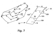
- Figures 6 and 7 show third and fourth exemplary embodiments of the gores and inflation pockets of the present invention.
- Gore 12 with long sides 12A and short sides 12B has a portion of a first end 30 folded over to overlap the gore.
- the long sides are t hen sealed along the overlapped portion, forming inflation pocket 25.
- the gores are then connected at points 16 and 22.
- the lines may be connected to the connections 16.
- Figure 7 shows an embodiment wherein the go res 12 further comprise flares 19. Additional material 18 at second end 32 is gathered to form flare 19. The lines may be connected to the flares 19.
- FIG 8 is an illustration of an inflated canopy of an embodiment of the present invention. Inflation pocke ts 25 are inflated, closing apertures 13. Thus, instead of acting as a single unit like the traditional canopy, each gore at first inflates separately at the crown. Then, as the gores are inflated, they work together to close the apertures and trap air as a single unit.
- Figure 9 is a cross sectional view of the inflated canopy shown in Figure 8 , showing the inflation pockets 25.
Landscapes
- Engineering & Computer Science (AREA)
- Aviation & Aerospace Engineering (AREA)
- Tents Or Canopies (AREA)
- Toys (AREA)
- Coloring Foods And Improving Nutritive Qualities (AREA)
- Heterocyclic Carbon Compounds Containing A Hetero Ring Having Nitrogen And Oxygen As The Only Ring Hetero Atoms (AREA)
- Compounds Of Unknown Constitution (AREA)
- Eye Examination Apparatus (AREA)
- Control Of Vending Devices And Auxiliary Devices For Vending Devices (AREA)
- Processes Of Treating Macromolecular Substances (AREA)
- Manufacture Of Porous Articles, And Recovery And Treatment Of Waste Products (AREA)
Abstract
Description
- This invention relates to a parachute. More specifically it relates to a method for constructing a parachute and the parachute constructed by this method, wherein the parachute can be constructed quic kly and at low cost.
- Parachutes are well known in the art for slowing the descent of object through the atmosphere, typically objects released from aircraft. Known parachutes typically comprise a plurality of gores connec ted between a plurality of radials. Each radial is then connected to a line secured to the object. These parachutes are costly as the connections between each gore and radial are time consuming. Further, connecting all the gores and radials is complicat ed by the bulkiness of the parachute as it is built by successively connecting more gores and radials.
- The known parachute construction is based on the use of woven fabric -type materials. Inexpensive non -woven fabrics and films cannot be used in th e same manner as woven materials. This keeps the costs high when using non -woven materials for parachute construction.
- Clearly, then, there is a longfelt need for a low cost parachute that does not require the costly and time consuming construction of known parachutes and can be constructed with low cost materials.
- The present invention broadly comprises a method for the construction of a parachute according to claim 1, and parachutes made by that method according to
claim 16. The parachute comprises a plurality of gores. At least one of the gores comprises an inflation pocket. - A general object of the present invention is to provide a parachute that can be manufactured quickly and inexpensively.
- A further object of the present invention is to provide a parachute than can be constructed with inexpensive non -woven fabrics or films.
- These and other objects, features and advantages of the present invention will become readily apparent to those having ordinary skill in the art upon a reading of the following detailed description of the invention in view of the drawings and claims.
- The nature and mode of operation of the present invention will now be more fully described in the following detailed description of the invention taken with the accompanying drawing figures, in which:
-
Figure 1 is a side view of a typical parachute constructed by known methods; -
Figure 2 is a view of a reinforcement strip and two gores of a typical parachute constructed by known methods; -
Figure 3 is a view of an embodiment of the present invention; -
Figure 4 is a schematic of the construction of a single gore of a first embodiment of the present invention; -
Figure 5 is a schematic of the construction of a single gore of a second embodiment of the present invention; -
Figure 6 illustrates a third embodiment of a single gore of the present invention; -
Figure 7 illustrates a fourth embodiment of a single gore of the present invention; -
Figure 8 illustrates an inflated canopy of an embodiment of the present invention; and, -
Figure 9 is a cross sectional view of the inflated canopy shown inFigure 8 , taken along line 9-9 inFigure 8 . - It should be appreciated that, in the detailed description of the invention which follows, like reference numbers on different drawing views are intended to identify identical structural elements of the invention in the respective views.
-
Figure 1 shows parachute 1 constructed using known methods. Parachute 1 comprisesgores 2 andradials 3 brought together atcrown 5, andlines 8 connected to the ends of the radials.Radials 3 typically comprisereinforcement strips 10. Each gore typically comprises 3 to 5 panels sewn together for a personnel type sized parachute. The gores are then connected toreinforcement strips 10, as shown inFigure 2 . As each additional gore and strip is attached, the parachute gets bulkier and more difficult to work with. When all the gores are connec ted together,reinforcement skirt band 7 is then sewn around the perimeter of the canopy andreinforcement vent band 4 is sewn over the crown, requiring additional time and effort.Lines 8 are then connected to the canopy. -
Figure 3 shows an embodiment of the present invention. Parachute 11 comprisesgores 12 joined atcrown 15. The gores are each connected to the adjacent gore atconnections 16. In a preferred embodiment, these two connections, at the crown and atconnection 16, are the only connections between the gores. However, it should be readily apparent to one skilled in the art that other configurations of attachments between the gores are possible, and these modifications are intended to be within the scope of the invention as claimed.Aperture 13 is open from theconnections 16 tocrown 15. Flare 19 is located at the opposite end of the gore from the crown. The lines are connected to the flares atconnection 21. In a preferred embodiment, each gore is made of a single piece of material. However, it should be readily apparent to one skilled in the art that gores can be made of multiple pieces of fabric, and these modifications are intended to be within the scope of the invention as claimed. -
Figure 4 shows the construction of each gore in a first embodiment. First, a rectangular piece of material is cut, havinglong sides 12A andshort sides 12B. (It should be readily apparent to one skilled in the art that non -rectangular gores may be used, and these modifications are within the scope of the invention as claimed.) The gore is then folded along a line parallel tolong sides 12A to bring together points A and C. The seam AC to B is then sealed. This forms inflation pocket 25 atfirst end 30. A t theopposite end 32, the material is collected together to apoint 21 to formflare 19. Each individual gore is then connected atpoints Figure 4 . In a preferred embodiment, these are the only two connection points between the go res. However, it should be readily apparent to one skilled in the art that more connections between the gore may be made between these two points to control the inflation rate of the canopy, and these modifications are intended to be within the scope of the invention as claimed. - The
flare 19 is not included in a second embodiment, illustrated inFigure 5 . In this embodiment the gores are connected atpoints connections 16. -
Figures 6 and7 show third and fourth exemplary embodiments of the gores and inflation pockets of the present invention. Gore 12 withlong sides 12A andshort sides 12B has a portion of afirst end 30 folded over to overlap the gore. The long sides are t hen sealed along the overlapped portion, forminginflation pocket 25. In a preferred embodiment, the gores are then connected atpoints Figure 6 , the lines may be connected to theconnections 16.Figure 7 shows an embodiment wherein the gores 12 further compriseflares 19.Additional material 18 atsecond end 32 is gathered to formflare 19. The lines may be connected to theflares 19. - When the present invention is deployed, some air passes through the apertures, which may be open. However, each inflation pocket inflates, which closes the apertures at the crown of the canopy. In this manner, the entire canopy is inflated.
Figure 8 is an illustration of an inflated canopy of an embodiment of the present invention.Inflation pocke ts 25 are inflated, closingapertures 13. Thus, instead of acting as a single unit like the traditional canopy, each gore at first inflates separately at the crown. Then, as the gores are inflated, they work together to close the apertures and trap air as a single unit.Figure 9 is a cross sectional view of the inflated canopy shown inFigure 8 , showing the inflation pockets 25. - All of the drawings of the present invention show canopies wherein each of the gores comprises an inflation pocket. How ever, it should be readily apparent to one skilled in the art that a canopy could be constructed with some gores comprising an inflation pocket and some gores not comprising an inflation pocket. All canopies having at least one gore comprising an inflation pocket are within the scope of the invention as claimed.
- Thus, it is seen that the objects of the present invention are efficiently obtained, although modifications and changes to the invention should be readily apparent to those having ordinary skill in the art, and these modifications are intended to be within the scope of the invention as claimed
Claims (24)
- A method for making a parachute (1) canopy from a suitable gore material characterized by the steps which comprise:(i) creating a pocket (25) in an interior side of at least one of a plurality of gores (12) having interior and exterior sides by a step selected from the group consisting of folding, gathering, and folding and gathering a piece of said gore material;(ii) connecting surfaces of said folded, gathered or folded and gathered gore material of a given gore (12) to form said pocket (25), and(iii) connecting said plurality of gores (12) together to form said parachute canopy.
- The method recited in Claim 1, characterized in that said gores (12) are generally triangular shaped.
- The method recited in Claim 1, characterized in that said plurality of gores (12) are connected together proximate to said pocket (25) of each of said gores (12).
- The method recited in Claim 1, characterized in that each of said plurality of gores (12) comprises a pocket (25).
- The method recited in Claim 1, characterized in that said surfaces of said gore material are connected by sealing.
- The method recited in Claim 1, characterized in that said pocket (25) is generally cone shaped.
- The method recited in Claim 1, characterized in that said gores (12) are fabricated from a single piece of said gore material.
- The method recited in Claim 1, characterized in that connections of adjacent gores (12) of the canopy are spaced from one another to form apertures therebetween.
- The method recited in Claim 8, characterized in that said gores (12) comprise an upper first end, and a lower second end opposite said first end, said method comprising the step of forming a skirt or tapering said lower second end of said gores (12) to form flared ends.
- The method recited in Claim 9, characterized in that said canopy comprises a crown at said upper first end, and the method includes the step of joining said plurality of gores at least at points in proximity to said crown.
- The method recited in Claim 1, characterized in that said plurality of gores (12) are formed by folding said gore material in half parallel to a pair of long sides, each of said gores having two short sides and two long sides; sealing a first short side of said plurality of gores to form an inflation pocket in said gores (12); connecting said plurality of gores (12) together proximate to said inflation pockets and at adjacent corners of a second short side of said plurality of gores (12).
- The method recited in Claim 1, characterized in that said plurality of gores (12) are generally rectangular shaped and formed by folding over an end portion of a first end of said gore material, said gores comprising two short sides and two long sides, wherein said first end is one of said short sides and a second end is an opposite short side; connecting by sealing said long sides of said folded over end portions to form an inflation pocket in each of said gores; connecting said plurality of gores proximate to said inflation pockets, and connecting adjacent corners of said short sides at said second end of said plurality of gores.
- The method recited in Claim 1, characterized in that the surfaces of said folded, gathered or folded and gathered gore material form pockets having a generally polyhedral configuration, said method including the step of connecting a plurality of said gores together in at least two places along sides of said gores.
- The method recited in Claim 13, characterized in that the plurality of surfaces of said pocket (25) form a trihedral shaped pocket.
- The method recited in Claim 1, characterized in that the canopy comprises gores (12) with and without inflation pockets (25), and said method includes the step of connecting adjacent gores together at least at two spaced locations to form apertures (13) therebetween.
- A parachute (1), characterized by a canopy of connected gores (12) having interior and exterior sides, wherein at least one of said gores (12) comprises a pocket (25) comprising connected surfaces of said interior side, wherein said connected surfaces of said pocket (25) comprise folded, gathered or folded and gathered gore material.
- The parachute (1) recited in Claim 16, characterized in that said gores (12) of said canopy are connected to each of two adjacent gores in at least two spaced locations along sides of said gores (12).
- The parachute recited in Claim 17, characterized in that said pockets (25) of said gores are generally triangular shaped.
- The parachute recited in Claim 17 , characterized in that said pockets (25) are in the form of a pouch or envelope.
- The parachute recited in Claim 16, characterized in that said gores (12) and pockets (12) are comprised of a single piece of material.
- The parachute recited in Claim 16, characterized in that gores (12) of said canopy further comprise an upper first end, a lower second end opposite said first end, a pocket at said upper first end and a skirt or tapered flare at said lower second end.
- The parachute recited in Claim 21, characterized in that said canopy comprises a crown (15) at said upper first end of said gores (12), wherein said gores (12) are connected in proximity to said crown (15).
- The parachute recited in Claim 16, characterized in that each gore (12) of said canopy comprises a pocket which is an inflation pocket (25).
- The parachute (1) recited in Claim 16, characterized in that said surfaces of said pocket (25) are connected by sealing.
Applications Claiming Priority (5)
| Application Number | Priority Date | Filing Date | Title |
|---|---|---|---|
| US631517 | 1990-12-21 | ||
| US40168702P | 2002-08-07 | 2002-08-07 | |
| US401687P | 2002-08-07 | ||
| US10/631,517 US6805324B2 (en) | 2002-08-07 | 2003-07-31 | Alternate methods of parachute construction |
| PCT/CA2003/001178 WO2004014728A1 (en) | 2002-08-07 | 2003-08-07 | Low cost parachute and method of making same |
Publications (2)
| Publication Number | Publication Date |
|---|---|
| EP1545973A1 EP1545973A1 (en) | 2005-06-29 |
| EP1545973B1 true EP1545973B1 (en) | 2009-04-08 |
Family
ID=31498706
Family Applications (1)
| Application Number | Title | Priority Date | Filing Date |
|---|---|---|---|
| EP03783864A Expired - Lifetime EP1545973B1 (en) | 2002-08-07 | 2003-08-07 | Low cost parachute and method of making same |
Country Status (12)
| Country | Link |
|---|---|
| US (1) | US6805324B2 (en) |
| EP (1) | EP1545973B1 (en) |
| KR (1) | KR20050026500A (en) |
| CN (1) | CN1675103A (en) |
| AT (1) | ATE427884T1 (en) |
| AU (1) | AU2003257298B8 (en) |
| CA (1) | CA2494919C (en) |
| DE (1) | DE60327085D1 (en) |
| ES (1) | ES2327038T3 (en) |
| IL (1) | IL166617A0 (en) |
| PL (1) | PL373113A1 (en) |
| WO (1) | WO2004014728A1 (en) |
Families Citing this family (3)
| Publication number | Priority date | Publication date | Assignee | Title |
|---|---|---|---|---|
| US20060192054A1 (en) * | 2004-10-13 | 2006-08-31 | Lachenmeier Timothy T | Inflatable and deployable systems with three dimensionally reinforced membranes |
| KR101715846B1 (en) * | 2014-09-29 | 2017-03-14 | 주식회사 진글라이더 | A parachute |
| US20250074605A1 (en) * | 2022-03-31 | 2025-03-06 | Nippon Kayaku Kabushiki Kaisha | Parachute, and safety device and flight vehicle provided with parachute |
Family Cites Families (31)
| Publication number | Priority date | Publication date | Assignee | Title |
|---|---|---|---|---|
| US458849A (en) * | 1891-09-01 | jacobs | ||
| US1562258A (en) * | 1924-05-19 | 1925-11-17 | James M Russell | Parachute |
| US1777441A (en) * | 1928-03-07 | 1930-10-07 | Malmer Ivar Valfrid | Parachute |
| US1862247A (en) * | 1929-09-20 | 1932-06-07 | Tricau Gabriel | Parachute |
| US1877227A (en) * | 1931-08-01 | 1932-09-13 | Cunningham William Leslie | Air-vent parachute |
| US2683575A (en) * | 1950-11-07 | 1954-07-13 | Pioneer Parachute Company Inc | Vented sector parachute |
| US2929588A (en) * | 1956-05-15 | 1960-03-22 | Northrop Corp | Annular ring parachute |
| US3136508A (en) * | 1962-10-26 | 1964-06-09 | Steinthal & Co Inc M | Parachute |
| GB1072251A (en) * | 1962-11-13 | 1967-06-14 | Hawker Siddeley Aviation Ltd | Improvements in or relating to parachutes |
| US3218007A (en) * | 1964-01-24 | 1965-11-16 | Reinhold J Gross | Parachute stability improvements |
| US3298639A (en) * | 1965-02-08 | 1967-01-17 | Pioneer Parachute Company Inc | Gliding parachute |
| GB1121397A (en) | 1966-03-25 | 1968-07-24 | Gq Parachute Comp Ltd | Improvements in or relating to parachutes |
| US3393885A (en) * | 1966-05-31 | 1968-07-23 | Otto W. Neumark | Parachutes |
| US3469805A (en) * | 1967-10-24 | 1969-09-30 | Us Navy | Method for inflating a balloon |
| US3507467A (en) * | 1968-08-07 | 1970-04-21 | Steinthal & Co Inc M | Skirt expander |
| FR1586956A (en) * | 1968-10-04 | 1970-03-06 | ||
| US3612449A (en) * | 1969-01-15 | 1971-10-12 | Oscar W Sepp | Boundary layer control parachutes |
| FR2055752B1 (en) * | 1969-08-08 | 1974-02-01 | Lemoigne Pierre | |
| US3655152A (en) * | 1970-03-17 | 1972-04-11 | Irvin Air Chute Ltd | Stretch fabric parachute canopy |
| GB1503738A (en) * | 1975-03-05 | 1978-03-15 | Irvin Ltd | Parachutes |
| FI54893C (en) * | 1977-04-22 | 1979-04-10 | Jarmo Uotila | FALLSKAERM |
| US4270714A (en) * | 1978-05-08 | 1981-06-02 | Jalbert Domina C | Parachute canopy |
| US4253627A (en) * | 1979-08-27 | 1981-03-03 | The United States Of America As Represented By The Secretary Of The Navy | Multi-layer ram air parachute canopy |
| US4343448A (en) * | 1980-02-29 | 1982-08-10 | The United States Of America As Represented By The Secretary Of The Air Force | All radial construction for continuous ribbon parachutes |
| US4588149A (en) | 1984-09-20 | 1986-05-13 | The United States Of America As Represented By The Secretary Of The Navy | Lowered opening shock parachute canopy |
| WO1990005663A1 (en) | 1988-11-24 | 1990-05-31 | Voile Systeme | Kite frame with inflatable compartment wing |
| US5037042A (en) * | 1990-04-18 | 1991-08-06 | The United States Of America As Represented By The Secretary Of The Navy | Stabilized square parachute |
| US5248117A (en) * | 1992-04-08 | 1993-09-28 | The United States Of America As Represented By The Secretary Of The Navy | Regulated drag area parachute |
| US5839695A (en) | 1996-05-20 | 1998-11-24 | Para-Flite, Inc. | Cruciform parachute design |
| GB2322606B (en) * | 1997-03-01 | 2001-04-11 | Wardle Storeys Ltd | Parachutes |
| US6328262B1 (en) * | 2000-11-08 | 2001-12-11 | The United States Of America As Represented By The Secretary Of The Army | Method for forming a parachute and a parachute formed thereby |
-
2003
- 2003-07-31 US US10/631,517 patent/US6805324B2/en not_active Expired - Fee Related
- 2003-08-07 DE DE60327085T patent/DE60327085D1/en not_active Expired - Lifetime
- 2003-08-07 CA CA002494919A patent/CA2494919C/en not_active Expired - Fee Related
- 2003-08-07 AU AU2003257298A patent/AU2003257298B8/en not_active Ceased
- 2003-08-07 KR KR1020057001081A patent/KR20050026500A/en not_active Ceased
- 2003-08-07 ES ES03783864T patent/ES2327038T3/en not_active Expired - Lifetime
- 2003-08-07 EP EP03783864A patent/EP1545973B1/en not_active Expired - Lifetime
- 2003-08-07 WO PCT/CA2003/001178 patent/WO2004014728A1/en not_active Ceased
- 2003-08-07 PL PL03373113A patent/PL373113A1/en unknown
- 2003-08-07 AT AT03783864T patent/ATE427884T1/en not_active IP Right Cessation
- 2003-08-07 CN CNA038190842A patent/CN1675103A/en active Pending
-
2005
- 2005-02-01 IL IL16661705A patent/IL166617A0/en unknown
Also Published As
| Publication number | Publication date |
|---|---|
| CA2494919A1 (en) | 2004-02-19 |
| EP1545973A1 (en) | 2005-06-29 |
| US6805324B2 (en) | 2004-10-19 |
| AU2003257298A1 (en) | 2004-02-25 |
| AU2003257298A2 (en) | 2004-02-25 |
| DE60327085D1 (en) | 2009-05-20 |
| KR20050026500A (en) | 2005-03-15 |
| AU2003257298B8 (en) | 2010-09-16 |
| US20040026568A1 (en) | 2004-02-12 |
| ATE427884T1 (en) | 2009-04-15 |
| IL166617A0 (en) | 2006-01-15 |
| ES2327038T3 (en) | 2009-10-23 |
| CA2494919C (en) | 2008-03-25 |
| PL373113A1 (en) | 2005-08-08 |
| CN1675103A (en) | 2005-09-28 |
| WO2004014728A1 (en) | 2004-02-19 |
| AU2003257298B2 (en) | 2010-02-25 |
Similar Documents
| Publication | Publication Date | Title |
|---|---|---|
| US4390149A (en) | Balloon envelope and method of fabricating same | |
| EP1545973B1 (en) | Low cost parachute and method of making same | |
| CZ196895A3 (en) | Air bag and process for producing thereof | |
| CA2425332C (en) | Cruciform parachute with arms attached | |
| AU723277B2 (en) | Device to control inflation characteristics of parachutes | |
| US5205517A (en) | Large parachute with means to positively expand and circularize the inlet area to facilitate deployment thereof | |
| ZA200501346B (en) | Alternate methods of parachute construction | |
| US4588149A (en) | Lowered opening shock parachute canopy | |
| CN115320857A (en) | An umbrella skirt for a large parachute | |
| CN114162333B (en) | Method for controlling opening performance of stamped parafoil by utilizing wing ribs | |
| US6328262B1 (en) | Method for forming a parachute and a parachute formed thereby | |
| CN109250123A (en) | A kind of split inflation ram air parachute | |
| CN206951575U (en) | Pollen separator | |
| US20030038215A1 (en) | Cruciform parachute assembly | |
| US4270714A (en) | Parachute canopy | |
| US3426397A (en) | Fabric connector | |
| US3507467A (en) | Skirt expander | |
| US2483423A (en) | Parachute | |
| US3452951A (en) | High drag efficiency parachute canopy | |
| CN112660453B (en) | Sealed packaging bag and packaging method for parachute for people | |
| EP0015778B1 (en) | Parachute with inflation assistance device | |
| CN119460116B (en) | A variable drag area parachute structure and deployment method | |
| EP0089142B1 (en) | Parachute | |
| CN213008769U (en) | Novel multifunctional parachute | |
| IL30676A (en) | Parachutes having wings detachable from the crown |
Legal Events
| Date | Code | Title | Description |
|---|---|---|---|
| PUAI | Public reference made under article 153(3) epc to a published international application that has entered the european phase |
Free format text: ORIGINAL CODE: 0009012 |
|
| 17P | Request for examination filed |
Effective date: 20050303 |
|
| AK | Designated contracting states |
Kind code of ref document: A1 Designated state(s): AT BE BG CH CY CZ DE DK EE ES FI FR GB GR HU IE IT LI LU MC NL PT RO SE SI SK TR |
|
| AX | Request for extension of the european patent |
Extension state: AL LT LV MK |
|
| DAX | Request for extension of the european patent (deleted) | ||
| GRAP | Despatch of communication of intention to grant a patent |
Free format text: ORIGINAL CODE: EPIDOSNIGR1 |
|
| GRAS | Grant fee paid |
Free format text: ORIGINAL CODE: EPIDOSNIGR3 |
|
| GRAA | (expected) grant |
Free format text: ORIGINAL CODE: 0009210 |
|
| AK | Designated contracting states |
Kind code of ref document: B1 Designated state(s): AT BE BG CH CY CZ DE DK EE ES FI FR GB GR HU IE IT LI LU MC NL PT RO SE SI SK TR |
|
| REG | Reference to a national code |
Ref country code: GB Ref legal event code: FG4D |
|
| REG | Reference to a national code |
Ref country code: CH Ref legal event code: EP |
|
| REG | Reference to a national code |
Ref country code: IE Ref legal event code: FG4D |
|
| REF | Corresponds to: |
Ref document number: 60327085 Country of ref document: DE Date of ref document: 20090520 Kind code of ref document: P |
|
| REG | Reference to a national code |
Ref country code: RO Ref legal event code: EPE |
|
| REG | Reference to a national code |
Ref country code: SE Ref legal event code: TRGR |
|
| PG25 | Lapsed in a contracting state [announced via postgrant information from national office to epo] |
Ref country code: SI Free format text: LAPSE BECAUSE OF FAILURE TO SUBMIT A TRANSLATION OF THE DESCRIPTION OR TO PAY THE FEE WITHIN THE PRESCRIBED TIME-LIMIT Effective date: 20090408 |
|
| NLV1 | Nl: lapsed or annulled due to failure to fulfill the requirements of art. 29p and 29m of the patents act | ||
| REG | Reference to a national code |
Ref country code: ES Ref legal event code: FG2A Ref document number: 2327038 Country of ref document: ES Kind code of ref document: T3 |
|
| PG25 | Lapsed in a contracting state [announced via postgrant information from national office to epo] |
Ref country code: AT Free format text: LAPSE BECAUSE OF FAILURE TO SUBMIT A TRANSLATION OF THE DESCRIPTION OR TO PAY THE FEE WITHIN THE PRESCRIBED TIME-LIMIT Effective date: 20090408 Ref country code: FI Free format text: LAPSE BECAUSE OF FAILURE TO SUBMIT A TRANSLATION OF THE DESCRIPTION OR TO PAY THE FEE WITHIN THE PRESCRIBED TIME-LIMIT Effective date: 20090408 Ref country code: PT Free format text: LAPSE BECAUSE OF FAILURE TO SUBMIT A TRANSLATION OF THE DESCRIPTION OR TO PAY THE FEE WITHIN THE PRESCRIBED TIME-LIMIT Effective date: 20090908 |
|
| PGFP | Annual fee paid to national office [announced via postgrant information from national office to epo] |
Ref country code: ES Payment date: 20090820 Year of fee payment: 7 |
|
| PG25 | Lapsed in a contracting state [announced via postgrant information from national office to epo] |
Ref country code: NL Free format text: LAPSE BECAUSE OF FAILURE TO SUBMIT A TRANSLATION OF THE DESCRIPTION OR TO PAY THE FEE WITHIN THE PRESCRIBED TIME-LIMIT Effective date: 20090408 |
|
| PGFP | Annual fee paid to national office [announced via postgrant information from national office to epo] |
Ref country code: DE Payment date: 20090821 Year of fee payment: 7 Ref country code: GB Payment date: 20090827 Year of fee payment: 7 Ref country code: RO Payment date: 20090803 Year of fee payment: 7 Ref country code: SE Payment date: 20090813 Year of fee payment: 7 Ref country code: TR Payment date: 20090807 Year of fee payment: 7 |
|
| PG25 | Lapsed in a contracting state [announced via postgrant information from national office to epo] |
Ref country code: EE Free format text: LAPSE BECAUSE OF FAILURE TO SUBMIT A TRANSLATION OF THE DESCRIPTION OR TO PAY THE FEE WITHIN THE PRESCRIBED TIME-LIMIT Effective date: 20090408 Ref country code: DK Free format text: LAPSE BECAUSE OF FAILURE TO SUBMIT A TRANSLATION OF THE DESCRIPTION OR TO PAY THE FEE WITHIN THE PRESCRIBED TIME-LIMIT Effective date: 20090408 |
|
| PGFP | Annual fee paid to national office [announced via postgrant information from national office to epo] |
Ref country code: CZ Payment date: 20090807 Year of fee payment: 7 |
|
| PLBE | No opposition filed within time limit |
Free format text: ORIGINAL CODE: 0009261 |
|
| STAA | Information on the status of an ep patent application or granted ep patent |
Free format text: STATUS: NO OPPOSITION FILED WITHIN TIME LIMIT |
|
| PG25 | Lapsed in a contracting state [announced via postgrant information from national office to epo] |
Ref country code: SK Free format text: LAPSE BECAUSE OF FAILURE TO SUBMIT A TRANSLATION OF THE DESCRIPTION OR TO PAY THE FEE WITHIN THE PRESCRIBED TIME-LIMIT Effective date: 20090408 |
|
| PGFP | Annual fee paid to national office [announced via postgrant information from national office to epo] |
Ref country code: BE Payment date: 20090814 Year of fee payment: 7 |
|
| 26N | No opposition filed |
Effective date: 20100111 |
|
| PG25 | Lapsed in a contracting state [announced via postgrant information from national office to epo] |
Ref country code: MC Free format text: LAPSE BECAUSE OF NON-PAYMENT OF DUE FEES Effective date: 20090831 Ref country code: BG Free format text: LAPSE BECAUSE OF FAILURE TO SUBMIT A TRANSLATION OF THE DESCRIPTION OR TO PAY THE FEE WITHIN THE PRESCRIBED TIME-LIMIT Effective date: 20090708 |
|
| REG | Reference to a national code |
Ref country code: CH Ref legal event code: PL |
|
| PG25 | Lapsed in a contracting state [announced via postgrant information from national office to epo] |
Ref country code: CH Free format text: LAPSE BECAUSE OF NON-PAYMENT OF DUE FEES Effective date: 20090831 Ref country code: LI Free format text: LAPSE BECAUSE OF NON-PAYMENT OF DUE FEES Effective date: 20090831 |
|
| PGFP | Annual fee paid to national office [announced via postgrant information from national office to epo] |
Ref country code: IT Payment date: 20090819 Year of fee payment: 7 |
|
| REG | Reference to a national code |
Ref country code: IE Ref legal event code: MM4A |
|
| PG25 | Lapsed in a contracting state [announced via postgrant information from national office to epo] |
Ref country code: IE Free format text: LAPSE BECAUSE OF NON-PAYMENT OF DUE FEES Effective date: 20090807 |
|
| PG25 | Lapsed in a contracting state [announced via postgrant information from national office to epo] |
Ref country code: GR Free format text: LAPSE BECAUSE OF FAILURE TO SUBMIT A TRANSLATION OF THE DESCRIPTION OR TO PAY THE FEE WITHIN THE PRESCRIBED TIME-LIMIT Effective date: 20090709 |
|
| BERE | Be: lapsed |
Owner name: IRVIN AEROSPACE CANADA, LTD Effective date: 20100831 |
|
| EUG | Se: european patent has lapsed | ||
| GBPC | Gb: european patent ceased through non-payment of renewal fee |
Effective date: 20100807 |
|
| PG25 | Lapsed in a contracting state [announced via postgrant information from national office to epo] |
Ref country code: LU Free format text: LAPSE BECAUSE OF NON-PAYMENT OF DUE FEES Effective date: 20090807 |
|
| REG | Reference to a national code |
Ref country code: FR Ref legal event code: ST Effective date: 20110502 |
|
| PG25 | Lapsed in a contracting state [announced via postgrant information from national office to epo] |
Ref country code: CZ Free format text: LAPSE BECAUSE OF NON-PAYMENT OF DUE FEES Effective date: 20100807 Ref country code: IT Free format text: LAPSE BECAUSE OF NON-PAYMENT OF DUE FEES Effective date: 20100807 |
|
| REG | Reference to a national code |
Ref country code: DE Ref legal event code: R119 Ref document number: 60327085 Country of ref document: DE Effective date: 20110301 |
|
| PG25 | Lapsed in a contracting state [announced via postgrant information from national office to epo] |
Ref country code: HU Free format text: LAPSE BECAUSE OF FAILURE TO SUBMIT A TRANSLATION OF THE DESCRIPTION OR TO PAY THE FEE WITHIN THE PRESCRIBED TIME-LIMIT Effective date: 20091009 |
|
| PG25 | Lapsed in a contracting state [announced via postgrant information from national office to epo] |
Ref country code: BE Free format text: LAPSE BECAUSE OF NON-PAYMENT OF DUE FEES Effective date: 20100831 Ref country code: FR Free format text: LAPSE BECAUSE OF NON-PAYMENT OF DUE FEES Effective date: 20100831 Ref country code: DE Free format text: LAPSE BECAUSE OF NON-PAYMENT OF DUE FEES Effective date: 20110301 |
|
| PG25 | Lapsed in a contracting state [announced via postgrant information from national office to epo] |
Ref country code: GB Free format text: LAPSE BECAUSE OF NON-PAYMENT OF DUE FEES Effective date: 20100807 |
|
| PG25 | Lapsed in a contracting state [announced via postgrant information from national office to epo] |
Ref country code: CY Free format text: LAPSE BECAUSE OF FAILURE TO SUBMIT A TRANSLATION OF THE DESCRIPTION OR TO PAY THE FEE WITHIN THE PRESCRIBED TIME-LIMIT Effective date: 20090408 |
|
| PGFP | Annual fee paid to national office [announced via postgrant information from national office to epo] |
Ref country code: FR Payment date: 20090914 Year of fee payment: 7 |
|
| REG | Reference to a national code |
Ref country code: ES Ref legal event code: FD2A Effective date: 20111019 |
|
| PG25 | Lapsed in a contracting state [announced via postgrant information from national office to epo] |
Ref country code: ES Free format text: LAPSE BECAUSE OF NON-PAYMENT OF DUE FEES Effective date: 20100808 Ref country code: RO Free format text: LAPSE BECAUSE OF NON-PAYMENT OF DUE FEES Effective date: 20100807 |
|
| PG25 | Lapsed in a contracting state [announced via postgrant information from national office to epo] |
Ref country code: SE Free format text: LAPSE BECAUSE OF NON-PAYMENT OF DUE FEES Effective date: 20100808 |
|
| PG25 | Lapsed in a contracting state [announced via postgrant information from national office to epo] |
Ref country code: TR Free format text: LAPSE BECAUSE OF NON-PAYMENT OF DUE FEES Effective date: 20100807 |