EP1545819B1 - Dispositif d'accouplement pour machine a enlevement de copeaux, et outil, tete de coupe et mandrin associes - Google Patents
Dispositif d'accouplement pour machine a enlevement de copeaux, et outil, tete de coupe et mandrin associes Download PDFInfo
- Publication number
- EP1545819B1 EP1545819B1 EP03741737A EP03741737A EP1545819B1 EP 1545819 B1 EP1545819 B1 EP 1545819B1 EP 03741737 A EP03741737 A EP 03741737A EP 03741737 A EP03741737 A EP 03741737A EP 1545819 B1 EP1545819 B1 EP 1545819B1
- Authority
- EP
- European Patent Office
- Prior art keywords
- cutting head
- holder
- tool
- coupling
- male
- Prior art date
- Legal status (The legal status is an assumption and is not a legal conclusion. Google has not performed a legal analysis and makes no representation as to the accuracy of the status listed.)
- Revoked
Links
Images


Classifications
-
- B—PERFORMING OPERATIONS; TRANSPORTING
- B23—MACHINE TOOLS; METAL-WORKING NOT OTHERWISE PROVIDED FOR
- B23B—TURNING; BORING
- B23B27/00—Tools for turning or boring machines; Tools of a similar kind in general; Accessories therefor
- B23B27/10—Cutting tools with special provision for cooling
-
- B—PERFORMING OPERATIONS; TRANSPORTING
- B23—MACHINE TOOLS; METAL-WORKING NOT OTHERWISE PROVIDED FOR
- B23B—TURNING; BORING
- B23B27/00—Tools for turning or boring machines; Tools of a similar kind in general; Accessories therefor
- B23B27/007—Tools for turning or boring machines; Tools of a similar kind in general; Accessories therefor for internal turning
-
- B—PERFORMING OPERATIONS; TRANSPORTING
- B23—MACHINE TOOLS; METAL-WORKING NOT OTHERWISE PROVIDED FOR
- B23B—TURNING; BORING
- B23B31/00—Chucks; Expansion mandrels; Adaptations thereof for remote control
- B23B31/02—Chucks
- B23B31/10—Chucks characterised by the retaining or gripping devices or their immediate operating means
- B23B31/11—Retention by threaded connection
-
- B—PERFORMING OPERATIONS; TRANSPORTING
- B23—MACHINE TOOLS; METAL-WORKING NOT OTHERWISE PROVIDED FOR
- B23B—TURNING; BORING
- B23B2220/00—Details of turning, boring or drilling processes
- B23B2220/12—Grooving
-
- B—PERFORMING OPERATIONS; TRANSPORTING
- B23—MACHINE TOOLS; METAL-WORKING NOT OTHERWISE PROVIDED FOR
- B23B—TURNING; BORING
- B23B2260/00—Details of constructional elements
- B23B2260/112—Projections
-
- B—PERFORMING OPERATIONS; TRANSPORTING
- B23—MACHINE TOOLS; METAL-WORKING NOT OTHERWISE PROVIDED FOR
- B23B—TURNING; BORING
- B23B2260/00—Details of constructional elements
- B23B2260/132—Serrations
-
- Y—GENERAL TAGGING OF NEW TECHNOLOGICAL DEVELOPMENTS; GENERAL TAGGING OF CROSS-SECTIONAL TECHNOLOGIES SPANNING OVER SEVERAL SECTIONS OF THE IPC; TECHNICAL SUBJECTS COVERED BY FORMER USPC CROSS-REFERENCE ART COLLECTIONS [XRACs] AND DIGESTS
- Y10—TECHNICAL SUBJECTS COVERED BY FORMER USPC
- Y10T—TECHNICAL SUBJECTS COVERED BY FORMER US CLASSIFICATION
- Y10T403/00—Joints and connections
- Y10T403/70—Interfitted members
- Y10T403/7005—Lugged member, rotary engagement
-
- Y—GENERAL TAGGING OF NEW TECHNOLOGICAL DEVELOPMENTS; GENERAL TAGGING OF CROSS-SECTIONAL TECHNOLOGIES SPANNING OVER SEVERAL SECTIONS OF THE IPC; TECHNICAL SUBJECTS COVERED BY FORMER USPC CROSS-REFERENCE ART COLLECTIONS [XRACs] AND DIGESTS
- Y10—TECHNICAL SUBJECTS COVERED BY FORMER USPC
- Y10T—TECHNICAL SUBJECTS COVERED BY FORMER US CLASSIFICATION
- Y10T407/00—Cutters, for shaping
- Y10T407/19—Rotary cutting tool
- Y10T407/1906—Rotary cutting tool including holder [i.e., head] having seat for inserted tool
-
- Y—GENERAL TAGGING OF NEW TECHNOLOGICAL DEVELOPMENTS; GENERAL TAGGING OF CROSS-SECTIONAL TECHNOLOGIES SPANNING OVER SEVERAL SECTIONS OF THE IPC; TECHNICAL SUBJECTS COVERED BY FORMER USPC CROSS-REFERENCE ART COLLECTIONS [XRACs] AND DIGESTS
- Y10—TECHNICAL SUBJECTS COVERED BY FORMER USPC
- Y10T—TECHNICAL SUBJECTS COVERED BY FORMER US CLASSIFICATION
- Y10T407/00—Cutters, for shaping
- Y10T407/22—Cutters, for shaping including holder having seat for inserted tool
Definitions
- the present invention relates to a coupling between a first part and a second part for use in chip removing machining, wherein the coupling comprises two interacting surfaces and members for forcing the surfaces together, wherein the surfaces are profiled with male and female members, respectively, in order to enable form locking against each other, that said coupling has a longitudinal centre line, wherein both the first part and the second part is provided with a central hole for clamping the parts against each other.
- the invention also relates separately to a tool, a cutting head and a holder.
- One object of the present invention is to provide a coupling between two tool parts, which coupling may transfer a large torque at the same time as the tool parts only may assume one single position in relation to each other.
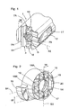
- the holder 1 shown in Fig. 1 may, for instance, be manufactured from steel or cemented carbide.
- the free end of the holder 1 shown in Fig. 1 comprises a front surface 3 and a threaded hole 5.
- the front surface 3 has a circular basic shape and comprises two sets of grooves 7A and 7B, respectively.
- Each set of grooves 7A and 7B, respectively, covers generally half the front surface 3 and comprises a number of identical channels or grooves 7A and 7B, respectively, spaced-apart from each other.
- the first grooves 7A have a first main direction S1 and the second grooves 7B have a second main direction S2, which main directions S1 and S2 are perpendicular to each other.
- the two sets of grooves 7A and 7B adjoin each other and overlap each other.
- Each first groove 7A in the first set intersects the envelope surface of the holder 1 in two points, while each second groove 7B in the second set of grooves intersects the envelope surface of the holder 1 in one point.
- Each groove 7A and 7B has a maximum width W and in absolute measurements, the groove has a width of 0,2-2 mm, preferably approx. 1,5 mm.
- Each groove has two flanks, which via a sharp or rounded transition connect to a bottom. The angle is within the interval 40°-80°, preferably 55°-60°.
- the first set of grooves 7A has been manufactured by slab milling or grinding, the feeding direction being parallel with the first main direction S1.
- the second set of grooves 7B has been machined with the same tool in a direction parallel with the second main direction S2.
- the tool will also machine material that is included in the first set of grooves 7A, which is seen in Fig. 1 , wherein entirely or partly pyramid-shaped first tips 10 are formed in the termination of the second set of grooves 7B in the first set of grooves 7A.
- the first set comprises three grooves 7A, while the second set comprises four grooves 7B.
- the arrangement of first and second sets of grooves 7A and 7B in the front surface 3 involves a significantly larger specific surface than if this surface would have been planar.
- the holder 1 according to Fig. 1 also comprises a channel 11 for cooling medium, wherein this channel 11 exits in a countersink 12 in the envelope surface of the holder 1.
- This channel 11 exits in a countersink 12 in the envelope surface of the holder 1.
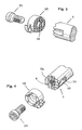
- the cutting head 15 according to the present invention shown in Fig. 2 is preferably intended to be used at internal turning.
- the cutting head 15 may, for instance, be manufactured from cemented carbide, cermet or high speed steel.
- the cutting head 15 is generally circular cylindrical with an edge portion 16 that extends radially beyond the rest of the cutting head 15.
- the edge portion 16 is in the conventional way provided with rake faces and flank surfaces.
- the cutting head 15 is also provided with a through-going central hole 14, which is intended to interact with a locking screw, see below.
- the cutting head 15 is provided with a support surface 17, which generally has a circular shape and comprises a third and a fourth set of grooves.
- the third set comprises a number of third grooves 18A having a third main direction S3, while the fourth set comprises a number of fourth grooves 18B having a fourth main direction S4, which main directions S3 and S4 are perpendicular to each other.
- three (3) third grooves 18A and three (3) fourth grooves 18B are arranged. Since the third and fourth main directions S3 and S4 generally intersect each other, entirely or partly pyramid-shaped second tips 19 are formed, however with a certain exception according to the principle of the present invention. This will be more thoroughly elucidated below.
- third and fourth grooves 18A and 18B As for the cross-sectional geometry of the third and fourth grooves, 18A and 18B, reference is made to what has been described above concerning the first and second grooves 7A and 7B.
- the arrangement of third and fourth sets of grooves 18A and 18B in the support surface 17 involves a significantly larger specific surface than if this surface would have been planar.
- the cutting head 15 according to Fig. 2 with the third and fourth sets of grooves in the support surface 17, may for instance be manufactured by direct pressing or injection moulding and subsequent sintering. As for the sets of grooves, these may also be produced by means of grinding.
- the mutual positioning of the components belonging to the cutting head 15 is such that an imaginary plane that extends in axial direction, through the centre of the hole 14 and in the fourth main direction S4 intersects the edge portion 16, the groove 18B, as well as an elongate ridge 20.
- the middle groove 18B in the fourth main direction S4 only extends across a part of the support surface 17, which more generally may be expressed as that at least one groove in one of the sets of grooves 18B extends across only a part of the support surface 17.
- This entails that an elongate ridge 20 is formed, which is not penetrated by the middle groove 18B in the set of grooves that has the fourth main direction S4.
- the ridge 20 constitutes a stop in the groove 18B.
- An imaginary extension line of the ridge extends offset or spaced from the longitudinal central axis of the tool.
- the making of the elongate ridge 20, which has the maximum extension thereof in the third main direction S3, entails that the cutting head 15 may only be mounted in one way in the holder 1, which is realized by studying the groove configuration for the front surface 3 of the holder 1.
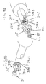
- Figs. 3-5 In order to illustrate the assembly of the cutting head 15 on the front surface 3 of the holder 1, reference is made to Figs. 3-5 .
- the cutting head 15 is fixed in relation to the holder 1 via a locking screw 21, which extends through the through-going hole 14 of the cutting head 15 and into the threaded hole 5 of the holder 1.
- the cutting head 15 is provided with a step or the like, in connection with the through-going hole 14, for interaction with a head of the locking screw 21.
- the elongate ridge 20 of the cutting head 15 is to be received in the first groove 7A that is positioned farthest out, which extends in the first main direction S1.
- the groove configurations of the front surface 3 and the support surface 17 it is realized that the only place where the elongate ridge 20 may be received is in the first groove 7A positioned farthest out in the first set of grooves. Thereby, the risk of the cutting head 15 being mounted in an incorrect position has been eliminated.
- the cutting head 15 is shown in a mounted state on the holder 1. Since the cutting head 15 only may be mounted in a single predetermined position on the holder 1, it is possible to arrange the cooling channel 11 in such a way that cooling medium coming out from the same is directed towards the edge portion 16 of the cutting head 15. Thereby, the possibilities are improved for a satisfactory cooling of the cutting edge when the same performs chip removing machining of a workpiece.
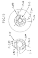
- each set of grooves 118A, 118B of the cutting head 115 comprises an additional groove in comparison with the cutting head 15.
- the sets of grooves 118A and 118B have a main direction each, S3 and S4, respectively, which are perpendicular to each other.
- the two middle grooves 118B in the fourth main direction S4 extend across only a part of the support surface 117. This entails that an elongate ridge 120, is formed, which is not penetrated by the middle grooves 118B in the set of grooves that has the fourth main direction S4.
- the making of the elongate ridge 120, which has the maximum extension thereof in the third main direction S3, entails that the cutting head 115 can only be mounted in one way in an appurtenant holder, having a groove configuration according to same principles as the holder 1, however fitting against the cutting head 115.
- An imaginary extension line of the elongated ridge 20 extends offset or spaced from a longitudinal central axis of the cutting head. As is seen in Fig.
- the pyramid-shaped tips 119 positioned closest to the hole 114 and the portion of the ridge 120 positioned closest to the hole 114 are provided with a recess 122, which is arranged for manufacturing-technical reasons since a certain amount of clearance is required around the hole 114.
- the alternative embodiment of a holder 201 illustrated in Figs. 7 and 8 comprises a front surface 203 as well as a threaded hole 205.
- the front surface 203 has a generally circular cross-section and has a groove 207, which is asymmetrically located in respect of a longitudinal centre line CL of the holder 201.
- the groove 207 is located substantially in one half of the front surface 203.
- the cutting head 215 illustrated in Fig. 9 is intended to be mounted on the holder 201.
- the cutting head 215 has a basic shape corresponding to the cutting heads 15; 115 and is provided with an edge portion 216 for groove slotting or parting.
- the cutting edge of the edge portion runs substantially parallel with the centre line CL.
- the cutting head 215 also has a support surface 217, which is intended to abut against the front surface 203 when the cutting head 215 is mounted on the holder 201.
- the cutting head 215 has a ridge 219 attached on the support surface, which is situated substantially on one of the halves of the support surface 217.
- the ridge 219 has a shape substantially complementary against the groove 207.
- the cutting head 215 can be mounted in only one way in the holder 201 by virtue of the location of the groove 207 and the ridge 219.
- a locking screw (not shown) thus extends through holes 205, 214 in the holder 201 and the cutting head 215, respectively.
- the holder 301 has in principle a corresponding groove 307B as the groove 207 of the holder 201.
- the holder 301 has an additional second groove 307A, wherein the main direction of the groove 307A is designated S301 and the main direction of the groove 307B is designated S302.
- the main directions S301 and S302 are located in a common plane and do not form a right angle with each other.
- the cutting head 315 is generally constructed correspondingly as the cutting heads 15; 115; 215.
- a locking screw 21 passes through a hole 314 of the cutting head 315 and extends into a threaded hole 305 of the holder 301, wherein the locking screw 21 provides a joint between the cutting head 315 and the holder 301.
- the cutting head 315 has a first ridge 319A and a second ridge 319B, which have the main directions S303 and S304, respectively.
- the main directions S303 and S304 are located in a common plane and do not form a right angle with each other.
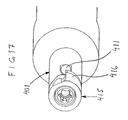
- the holder 401 is provided with two grooves 407A and 407B, the main directions of which are designated S401 and S402, respectively. Said main directions S401 and S402 are located in a common plane and form a right angle with each other.
- the cutting head 415 is generally constructed correspondingly as the cutting head 315, however the main directions S403 and S404 for the ridges 419A and 419B form a right angle with each other.
- the cutting head 415 is intended to be mounted on the holder 401, wherein the ridges 419a and 419B are received in the grooves 407A and 407B, respectively.
- the holder (1; 201; 301; 401) is integrated with a shaft, which is intended to be mounted in a machine tool.
- the front surface 3; 203; 303; 403 and the support surface 17; 117; 217; 317; 417 preferably have an extension perpendicularly to the longitudinal centre line CL of the tool.
- the cutting heads 15; 115; 215; 315; 415 only can be mounted in one way in the appurtenant holder 1; 201; 301; 401, which has been provided by the location of the grooves and the ridges. This is of particular importance in order for the cooling of the cutting head 15; 115; 215; 315; 415 of the tool to work.
- cooling medium from the cooling medium channel 11; 211; 311; 411 will be directed towards the edge portion 16; 116; 216; 316; 416 of the cutting head 15; 115; 215; 315; 415.
- Fig. 17 for the holder 401 and the cutting head 415, wherein is seen that an imaginary extension of the cooling medium channel 411 intersects the edge portion 416.
- the same design is preferably applicable generally for all the above-described embodiments.
- the male and the female members have a mutual flank abutment (linear abutment) but that there need not be a complete correspondence as regards the shape of the male and the female members.
- a generally protruding part which interacts with a recess having a shape so that form locking is provided between the interacting members is also feasible within the scope of the present invention.
- the max. and min. points of the interacting male and female members, respectively become located at a distance from the centre line of the central hole.
- the tool according to the present invention and the components included in this tool that it preferably involves small dimensions.
- the diameter/across corner dimension for the tool/cutting head/holder is normally within the interval of 5-10 mm.
- the protrusion of the edge portion 16; 116; 216; 316; 416 from the rest of the cutting head 15; 115; 215; 315; 415 is normally within the interval of 2-5 mm.
- the asymmetrical location of the grooves 207; 307A, 307B; 407A, 407B involves that these are given a certain elastic deformation, i.e. that they widen somewhat at interaction with an appurtenant ridge 219; 319A, 319B; 419A, 419B. This is facilitated by the asymmetrical location, since there is significantly less material on one of the sides of the grooves 207; 307A, 307B; 407A, 407B.
- the elastic deformation promotes a satisfactory abutment between the front surface 3; 203; 303; 403 and the support surface 17; 117; 217; 317; 417.
- the elongate ridge 20; 120 is arranged on the cutting head 15; 115.
- This means that the new cutting heads 15; 115 according to the present invention may in principle fit in a holder according to US-A-6 146 060 , which of course is an exceptionally great advantage.
- the groove configurations swap locations i.e. that the front surface of the holder is provided with an elongate ridge. This is generally applicable for all the above-described embodiments.
- the elongate ridge 20; 120 has been given a location on the cutting head 15; 115 as far away as possible from the edge portion 16; 116.
- alternative locations of the elongate ridge on the cutting head are also feasible within the scope of the invention.
- the elongate ridge may still have an extension in the third main direction S3 but be positioned closer to the edge portion 16; 116.
- the elongate ridge may also have an extension in the fourth main direction S4. It is generally applicable that in a modification of the location of the elongate ridge on the cutting head 15; 115, a corresponding modification of the groove configuration on the front surface 3 of the holder 1 must be carried out.
Landscapes
- Engineering & Computer Science (AREA)
- Mechanical Engineering (AREA)
- Cutting Tools, Boring Holders, And Turrets (AREA)
- Milling Processes (AREA)
- Drilling Tools (AREA)
- Scissors And Nippers (AREA)
- Automatic Tool Replacement In Machine Tools (AREA)
Claims (10)
- Dispositif d'accouplement, entre une première partie (1 ; 201 ; 301 ; 401) et une deuxième partie (15 ; 115 ; 215 ; 315 ; 415) pour utilisation dans l'usinage par enlèvement de copeaux, dans lequel le dispositif d'accouplement comprend deux surfaces à interaction (3, 17 ; 117 ; 203 ; 217 ; 303 ; 317 ; 403 ; 417) et des organes (21) pour forcer les surfaces (3, 17 ; 117 ; 203 ; 217 ; 303 ; 317 ; 403 ; 417) ensemble, dans lequel les surfaces (3, 17 ; 117 ; 203 ; 217 ; 303 ; 317 ; 403 ; 417) sont profilées, avec des organes mâles et femelles, respectivement (10, 19, 20 ; 119, 120 ; 219 ; 319A, 319B ; 419A, 419B et 7A, 7B, 18A, 18B ; 118A, 118B ; 207 ; 307A, 307B ; 407A, 407B, respectivement) de manière à permettre un verrouillage par interaction de formes les unes contre les autres, dans lequel ledit dispositif d'accouplement présente un axe central (CL) longitudinal, dans lequel à la fois première partie (1 ; 201 ; 301 ; 401) et la deuxième partie (15 ; 115 ; 215 ; 315 ; 415) sont munies d'un trou central (5, 14 ; 114 ; 205, 214 ; 305, 314 ; 405 ; 414) pour serrer les parties (1 ; 15 ; 115 ; 201 ; 215 ; 301 ; 315 ; 401 ; 415) les unes contre les autres, caractérisé en ce que les organes mâles et femelles (20 ; 120 ; 219 ; 319A, 319B ; 419A, 419B et 7A, 207 ; 307A, 307B ; 407A, 407B, respectivement) sont formés de manière que les parties (1 ; 15 ; 115 ; 201 ; 215 ; 301 ; 315 ; 401 ; 415) puissent être montées dans une seule position les unes par rapport aux autres.
- Dispositif d'accouplement selon la revendication 1, caractérisé en ce que des points maximaux et minimaux des organes mâles et femelles (20 ; 7A ; 120 ; 219, 207 ; 319A ; 319B ; 307A, 307B ; 419A ; 419B ; 407A, 407B), respectivement en interaction sont positionnés à une distance de l'axe central (CL) des trous centraux (205; 214 ; 305 ; 314 ; 405; 414).
- Dispositif d'accouplement selon la revendication 1 ou 2, caractérisé en ce que la première partie (1 ; 201 ; 301 ; 401) présente un canal (11 ; 211 ; 311 ; 411) pour du fluide de refroidissement sortant dans la surface d'enveloppe de la première partie (1 ; 201 ; 301 ; 401).
- Dispositif d'accouplement selon l'une quelconque des revendications précédentes, caractérisé en ce que les surfaces (3, 17 ; 117 ; 203, 217 ; 303 ; 317 ; 403, 417) en interaction présentent une extension perpendiculairement à l'axe central CL longitudinal de l'outil.
- Outil pour machine à enlèvement de copeaux, comprenant un dispositif d'accouplement, entre une première partie (1 ; 201 ; 301 ; 401) et une deuxième partie (15 ; 115 ; 215 ; 315 ; 415) selon la revendication 1, dans lequel le dispositif d'accouplement comprend deux surfaces à interaction (3, 17 ; 117 ; 203 ; 217 ; 303 ; 317 ; 403 ; 417) et des organes (21) pour forcer les surfaces (3, 17 ; 117 ; 203 ; 217 ; 303 ; 317 ; 403 ; 417) ensemble, dans lequel les surfaces (3, 17 ; 117 ; 203 ; 217 ; 303 ; 317 ; 403 ; 417) sont profilées, avec des organes mâles et femelles, (10, 19, 119 ; 219 ; 319A ; 319B ; 419A, 419B et 7A, 7B, 18A, 18B, 118A, 118B ; 207 ; 307A, 307B ; 407A, 407B, respectivement) de manière à permettre un verrouillage par interaction de formes les unes contre les autres, dans lequel ledit outil présente un axe central (CL) longitudinal, dans lequel à la fois première partie (1 ; 201 ; 301 ; 401) et la deuxième partie (15 ; 115 ; 215 ; 315 ; 415) sont munies d'un trou central (5, 14 ; 114 ; 205, 214 ; 305, 314 ; 405 ; 414) pour serrer les parties (1 ; 15 ; 115 ; 201 ; 215 ; 301 ; 315 ; 401 ; 415) les unes contre les autres, caractérisé en ce que les organes mâles et femelles (10, 19, 119 ; 219 ; 319A ; 319B ; 419A, 419B et 7A, 7B, 18A, 18B, 118A, 118B ; 207 ; 307A, 307B ; 407A, 407B, respectivement) sont formés de manière que les parties (1 ; 15 ; 115 ; 201 ; 215 ; 301 ; 315 ; 401 ; 415) puissent être montées dans une seule position les unes par rapport aux autres.
- Outil selon la revendication 5, caractérisé en ce que les organes mâles et femelles (207 ; 307A ; 307B ; 407A, 407B) en interaction sont disposées asymétriquement par rapport au trou central (205, 214 ; 305, 314 ; 405 ; 414).
- Outil selon la revendication 5 ou 6, caractérisé en ce que la première partie comprend un canal (11 ; 211 ; 311 ; 411) pour du fluide de refroidissement sortant dans la surface d'enveloppe de la première partie (1 ; 201 ; 301 ; 401).
- Tête de coupe incluse dans un outil pour une machine à enlèvement de copeaux selon la revendication 5, dans laquelle la tête de coupe (15 ; 115 ; 215 ; 315 ; 415) comprend une surface (17 ; 117 ; 217 ; 317 ; 417), destinée à interagir avec une autre surface incluse dans l'outil, comprenant des organes (21) pour forcer la surface (17 ; 117 ; 217 ; 317 ; 417) de la tête de coupe, conjointement avec l'autre surface, dans lequel la surface (17 ; 117 ; 217 ; 317 ; 417) de la tête de coupe (15 ; 115 ; 215 ; 315 ; 415) est profilée, avec des organes mâles ou femelles (10, 19 ; 119, 219 ; 319A, 319B ; 419A, 419B) de manière à permettre un verrouillage par interaction de formes contre la deuxième surface, en ce que la tête de coupe (15 ; 115 ; 215 ; 315 ; 415) présente un axe central (CL) longitudinal, dans lequel la tête de coupe (15 ; 115 ; 215 ; 315 ; 415) est munie d'un trou central (14 ; 114 ; 214 ; 314 ; 414), caractérisée en ce qu'elle est applicable pour la surface 17 ; 117 ; 217 ; 317 ; 417) de la tête de coupe (15 ; 115 ; 215 ; 315 ; 415), en ce que les organes (20 ; 120 ; 219 ; 319A, 319B ; 419A, 419B), qui vont faire que la surface (17 ; 117 ; 217 ; 317 ; 417) de la tête de coupe (15 ; 115 ; 215 ; 315 ; 415) puisse être montée dans une seule position les unes par rapport à la deuxième surface, sont situés asymétriquement par rapport au trou central (14 ; 114 ; 214 ; 314 ; 414).
- Mandrin dans un outil pour une machine à enlèvement de copeaux selon la revendication 5, dans lequel le mandrin (1 ; 201 ; 301 ; 401) comprend une surface (3 ; 203 ; 303 ; 403), destinée à interagir avec une autre surface incluse dans l'outil, comprenant des organes de manière à forcer la surface (3 ; 203 ; 303 ; 403) du mandrin (1 ; 201 ; 301 ; 401) ensemble avec la deuxième surface, dans lequel la surface (3 ; 203 ; 303 ; 403) du mandrin (1 ; 201 ; 301 ; 401) est profilée, avec des organes mâles ou femelles (7A, 7B, 18A, 18B ; 118A, 118B ; 207 ; 307A, 307B ; 407A, 407B), de manière à permettre un verrouillage par interaction de formes contre la deuxième surface, en ce que ledit mandrin (1 ; 201 ; 301 ; 401) présente un axe central (CL) longitudinal, dans lequel le mandrin (1 ; 201 ; 301 ; 401) est muni d'un trou central (5 ; 205 ; 305, 405), caractérisé en ce qu'il est applicable pour la surface (3 ; 203 ; 303 ; 403) du mandrin (1 ; 201 ; 301 ; 401), en ce que les organes mâles ou femelles (7A ; 207 ; 307A, 307B ; 407A, 407B) qui vont faire que la surface (3 ; 203 ; 303 ; 403) du mandrin (1 ; 201 ; 301 ; 401) puisse être montée dans une seule position les unes par rapport à la deuxième surface, sont situés asymétriquement par rapport au trou central (5 ; 205 ; 305, 405).
- Mandrin selon la revendication 9, caractérisé en ce qu'il (1 ; 201 ; 301 ; 401) comprend un canal (11 ; 211 ; 311 ; 411) pour du fluide de refroidissement sortant dans sa surface d'enveloppe.
Applications Claiming Priority (5)
| Application Number | Priority Date | Filing Date | Title |
|---|---|---|---|
| SE0202029A SE525583C2 (sv) | 2002-07-01 | 2002-07-01 | Koppling med profilerade ytor vid verktyg för spånavskiljande bearbetning |
| SE0202029 | 2002-07-01 | ||
| SE0203356 | 2002-11-14 | ||
| SE0203356A SE526174C2 (sv) | 2002-07-01 | 2002-11-14 | Koppling vid verktyg för spånavskiljande bearbetning där kopplingsdelarna endast kan monteras i ett läge |
| PCT/SE2003/001165 WO2004002662A1 (fr) | 2002-07-01 | 2003-06-27 | Dispositif d'accouplement pour machine a enlevement de copeaux, et outil, tete de coupe et mandrin associes |
Publications (2)
| Publication Number | Publication Date |
|---|---|
| EP1545819A1 EP1545819A1 (fr) | 2005-06-29 |
| EP1545819B1 true EP1545819B1 (fr) | 2011-11-30 |
Family
ID=26655711
Family Applications (1)
| Application Number | Title | Priority Date | Filing Date |
|---|---|---|---|
| EP03741737A Revoked EP1545819B1 (fr) | 2002-07-01 | 2003-06-27 | Dispositif d'accouplement pour machine a enlevement de copeaux, et outil, tete de coupe et mandrin associes |
Country Status (6)
| Country | Link |
|---|---|
| US (1) | US7641423B2 (fr) |
| EP (1) | EP1545819B1 (fr) |
| CN (1) | CN1665627B (fr) |
| AT (1) | ATE535330T1 (fr) |
| SE (1) | SE526174C2 (fr) |
| WO (1) | WO2004002662A1 (fr) |
Families Citing this family (16)
| Publication number | Priority date | Publication date | Assignee | Title |
|---|---|---|---|---|
| SE527850C2 (sv) * | 2004-02-24 | 2006-06-20 | Sandvik Intellectual Property | Skärverktyg samt grundkropp med kopplingsytor försedda med åsar |
| SE528811C2 (sv) * | 2005-03-16 | 2007-02-20 | Sandvik Intellectual Property | Skär och verktyg för spånavskiljande bearbetning med vinklade ingreppsmedel, samt tillsats för dylika verktyg |
| DE102005029758B3 (de) * | 2005-06-20 | 2007-01-04 | MAPAL Fabrik für Präzisionswerkzeuge Dr. Kress KG | Schnittstelle eines Werkzeugsystems |
| SE528751C2 (sv) * | 2005-06-27 | 2007-02-06 | Sandvik Intellectual Property | Svarvverktyg och indexerbart svarvskär, samt tillsats för dylika svarvverktyg |
| US8079785B2 (en) * | 2006-02-28 | 2011-12-20 | Kennametal Inc. | Tool holder assembly |
| US20070274794A1 (en) * | 2006-05-26 | 2007-11-29 | Cirino Thomas J | Oblique angle serration location and drive interface |
| DE102006035182A1 (de) * | 2006-07-29 | 2008-01-31 | Hartmetall-Werkzeugfabrik Paul Horn Gmbh | Werkzeugsystem |
| JP5559470B2 (ja) * | 2008-10-29 | 2014-07-23 | 三菱マテリアル株式会社 | 内径加工工具および内径加工方法 |
| JP5361570B2 (ja) * | 2009-06-29 | 2013-12-04 | 京セラ株式会社 | 内径加工用工具 |
| IL204008A (en) * | 2010-02-17 | 2014-02-27 | Iscar Ltd | Tool connection |
| IL211113A (en) * | 2011-02-08 | 2015-09-24 | Iscar Ltd | Cutting tools and a tool for him |
| US9120154B2 (en) * | 2013-02-14 | 2015-09-01 | Iscar, Ltd. | Single-sided square-shaped indexable cutting insert and cutting tool |
| EP2883640B1 (fr) * | 2013-12-13 | 2017-05-17 | Sandvik Intellectual Property AB | Outil de coupe avec des éléments de butée et porte-outil et insert de coupe pour celui-ci |
| KR102524260B1 (ko) * | 2018-10-10 | 2023-04-20 | 스미또모 덴꼬오 하드메탈 가부시끼가이샤 | 절삭 인서트 및 절삭 공구 |
| CN110360244B (zh) * | 2019-08-21 | 2023-08-22 | 山东雷沃传动有限公司 | 一种摩擦片式超越离合器及包含其的装载机 |
| US11786982B2 (en) * | 2021-04-26 | 2023-10-17 | Kennametal Inc. | Cutting tool comprising toolholder and round cutting insert and method for repositioning the round cutting insert in a pocket of the toolholder |
Family Cites Families (15)
| Publication number | Priority date | Publication date | Assignee | Title |
|---|---|---|---|---|
| DE3448086C2 (fr) | 1984-01-26 | 1991-12-19 | Hartmetall-Werkzeugfabrik Paul Horn Gmbh, 7400 Tuebingen, De | |
| DE3402547A1 (de) * | 1984-01-26 | 1985-08-08 | Hartmetall-Werkzeugfabrik Paul Horn GmbH, 7400 Tübingen | Wechselschneidkoerper, insbesondere fuer ein inneneinstich- und zirkular-werkzeug |
| FR2590191B1 (fr) * | 1985-11-18 | 1989-09-15 | Recoules Et Fils Sa | Outil de coupe monobloc a plusieurs etages pour le prealesage et l'alesage |
| IL112818A (en) * | 1995-02-28 | 1999-10-28 | Iscar Ltd | Tool holder having a grooved seat |
| SE509363C2 (sv) * | 1995-09-25 | 1999-01-18 | Sandvik Ab | Fastspänningsanordning fjör skärplattor samt skärplatta avsedd för dylik anordning |
| IL115544A (en) * | 1995-10-06 | 1998-12-06 | Iscar Ltd | Cutting tool system with replaceable adapter |
| SE510533C2 (sv) * | 1996-11-04 | 1999-05-31 | Seco Tools Ab | Verktyg för skärande bearbetning |
| SE511390C2 (sv) * | 1997-03-05 | 1999-09-20 | Sandvik Ab | Anordning vid fastspänning av skärplattor för skärande metallbearbetning |
| SE511565C2 (sv) * | 1997-04-28 | 1999-10-18 | Sandvik Ab | Verktyg för skärande bearbetning |
| SE509540C2 (sv) * | 1997-06-30 | 1999-02-08 | Seco Tools Ab | Verktyg |
| SE516973C2 (sv) * | 1999-02-04 | 2002-03-26 | Sandvik Ab | Verktyg för avstickning och spårsvarvning försett med tandade kopplingsytor |
| SE517192C2 (sv) * | 1999-02-26 | 2002-05-07 | Sandvik Ab | Verktygskoppling |
| CN2456870Y (zh) * | 2000-12-13 | 2001-10-31 | 陈颢 | 机夹可重磨刀具 |
| SE523766C2 (sv) * | 2001-05-18 | 2004-05-18 | Seco Tools Ab | Verktyg för profilsvarvning med frammatningsbart skär |
| IL157032A (en) * | 2003-07-21 | 2007-10-31 | Moshe Elbaz | Cutting head for rotary cutting tool |
-
2002
- 2002-11-14 SE SE0203356A patent/SE526174C2/sv not_active IP Right Cessation
-
2003
- 2003-06-27 AT AT03741737T patent/ATE535330T1/de active
- 2003-06-27 CN CN038155052A patent/CN1665627B/zh not_active Expired - Fee Related
- 2003-06-27 EP EP03741737A patent/EP1545819B1/fr not_active Revoked
- 2003-06-27 WO PCT/SE2003/001165 patent/WO2004002662A1/fr not_active Application Discontinuation
- 2003-07-01 US US10/609,489 patent/US7641423B2/en not_active Expired - Fee Related
Also Published As
| Publication number | Publication date |
|---|---|
| CN1665627B (zh) | 2012-05-23 |
| SE0203356D0 (sv) | 2002-11-14 |
| WO2004002662A1 (fr) | 2004-01-08 |
| CN1665627A (zh) | 2005-09-07 |
| ATE535330T1 (de) | 2011-12-15 |
| US20040057785A1 (en) | 2004-03-25 |
| EP1545819A1 (fr) | 2005-06-29 |
| SE0203356L (sv) | 2004-01-02 |
| SE526174C2 (sv) | 2005-07-19 |
| US7641423B2 (en) | 2010-01-05 |
Similar Documents
| Publication | Publication Date | Title |
|---|---|---|
| EP1545818B1 (fr) | Dispositif d'accouplement pour machine a enlevement de copeaux, et outil, tete de coupe et mandrin associe | |
| EP1545819B1 (fr) | Dispositif d'accouplement pour machine a enlevement de copeaux, et outil, tete de coupe et mandrin associes | |
| CA2789004C (fr) | Accouplement d'outils | |
| JP4981787B2 (ja) | 工具組立体 | |
| RU2446919C2 (ru) | Инструмент с устанавливаемой с возможностью раскрепления самозажимной режущей головкой | |
| EP1328366B1 (fr) | Outil pivotant dont l'extremite libre d'enlevement de copeaux est pourvue d'une partie active remplacable | |
| EP1152858B1 (fr) | Outil et tete coupante pour dispositif d'usinage par enlevement de matiere | |
| US6270294B1 (en) | Tool for parting and grooving | |
| US8708613B2 (en) | Left-handed and right-handed cutting tool | |
| KR101568053B1 (ko) | 절삭 공구의 클램핑 기구 | |
| WO2006130073A1 (fr) | Plaquette et outil de fraisage, et plaque de calage destinee a ces outils | |
| EP1635976B1 (fr) | Plaquette de coupe | |
| KR100994665B1 (ko) | 칩 제거 가공용 공구의 커플링, 공구, 커팅 헤드 및 홀더 | |
| CN110814370A (zh) | 用于切削机的切削刀具 | |
| EP1020246A1 (fr) | Outil de coupe |
Legal Events
| Date | Code | Title | Description |
|---|---|---|---|
| PUAI | Public reference made under article 153(3) epc to a published international application that has entered the european phase |
Free format text: ORIGINAL CODE: 0009012 |
|
| 17P | Request for examination filed |
Effective date: 20041122 |
|
| AK | Designated contracting states |
Kind code of ref document: A1 Designated state(s): AT BE BG CH CY CZ DE DK EE ES FI FR GB GR HU IE IT LI LU MC NL PT RO SE SI SK TR |
|
| GRAP | Despatch of communication of intention to grant a patent |
Free format text: ORIGINAL CODE: EPIDOSNIGR1 |
|
| RIN1 | Information on inventor provided before grant (corrected) |
Inventor name: VIRTANEN, KAJ Inventor name: BLUECHER, MATS Inventor name: ERIKSSON, THOMAS Inventor name: LUNDEQVIST, JAN-OLOV Inventor name: BOMAN, JONAS |
|
| GRAS | Grant fee paid |
Free format text: ORIGINAL CODE: EPIDOSNIGR3 |
|
| GRAA | (expected) grant |
Free format text: ORIGINAL CODE: 0009210 |
|
| STAA | Information on the status of an ep patent application or granted ep patent |
Free format text: STATUS: THE PATENT HAS BEEN GRANTED |
|
| AK | Designated contracting states |
Kind code of ref document: B1 Designated state(s): AT BE BG CH CY CZ DE DK EE ES FI FR GB GR HU IE IT LI LU MC NL PT RO SE SI SK TR |
|
| REG | Reference to a national code |
Ref country code: GB Ref legal event code: FG4D Ref country code: CH Ref legal event code: EP |
|
| REG | Reference to a national code |
Ref country code: IE Ref legal event code: FG4D |
|
| REG | Reference to a national code |
Ref country code: DE Ref legal event code: R096 Ref document number: 60339280 Country of ref document: DE Effective date: 20120209 |
|
| REG | Reference to a national code |
Ref country code: NL Ref legal event code: VDEP Effective date: 20111130 |
|
| PG25 | Lapsed in a contracting state [announced via postgrant information from national office to epo] |
Ref country code: NL Free format text: LAPSE BECAUSE OF FAILURE TO SUBMIT A TRANSLATION OF THE DESCRIPTION OR TO PAY THE FEE WITHIN THE PRESCRIBED TIME-LIMIT Effective date: 20111130 Ref country code: BE Free format text: LAPSE BECAUSE OF FAILURE TO SUBMIT A TRANSLATION OF THE DESCRIPTION OR TO PAY THE FEE WITHIN THE PRESCRIBED TIME-LIMIT Effective date: 20111130 Ref country code: PT Free format text: LAPSE BECAUSE OF FAILURE TO SUBMIT A TRANSLATION OF THE DESCRIPTION OR TO PAY THE FEE WITHIN THE PRESCRIBED TIME-LIMIT Effective date: 20120330 Ref country code: SE Free format text: LAPSE BECAUSE OF FAILURE TO SUBMIT A TRANSLATION OF THE DESCRIPTION OR TO PAY THE FEE WITHIN THE PRESCRIBED TIME-LIMIT Effective date: 20111130 Ref country code: SI Free format text: LAPSE BECAUSE OF FAILURE TO SUBMIT A TRANSLATION OF THE DESCRIPTION OR TO PAY THE FEE WITHIN THE PRESCRIBED TIME-LIMIT Effective date: 20111130 Ref country code: GR Free format text: LAPSE BECAUSE OF FAILURE TO SUBMIT A TRANSLATION OF THE DESCRIPTION OR TO PAY THE FEE WITHIN THE PRESCRIBED TIME-LIMIT Effective date: 20120301 |
|
| PG25 | Lapsed in a contracting state [announced via postgrant information from national office to epo] |
Ref country code: CY Free format text: LAPSE BECAUSE OF FAILURE TO SUBMIT A TRANSLATION OF THE DESCRIPTION OR TO PAY THE FEE WITHIN THE PRESCRIBED TIME-LIMIT Effective date: 20111130 |
|
| PG25 | Lapsed in a contracting state [announced via postgrant information from national office to epo] |
Ref country code: BG Free format text: LAPSE BECAUSE OF FAILURE TO SUBMIT A TRANSLATION OF THE DESCRIPTION OR TO PAY THE FEE WITHIN THE PRESCRIBED TIME-LIMIT Effective date: 20120229 Ref country code: EE Free format text: LAPSE BECAUSE OF FAILURE TO SUBMIT A TRANSLATION OF THE DESCRIPTION OR TO PAY THE FEE WITHIN THE PRESCRIBED TIME-LIMIT Effective date: 20111130 Ref country code: SK Free format text: LAPSE BECAUSE OF FAILURE TO SUBMIT A TRANSLATION OF THE DESCRIPTION OR TO PAY THE FEE WITHIN THE PRESCRIBED TIME-LIMIT Effective date: 20111130 Ref country code: DK Free format text: LAPSE BECAUSE OF FAILURE TO SUBMIT A TRANSLATION OF THE DESCRIPTION OR TO PAY THE FEE WITHIN THE PRESCRIBED TIME-LIMIT Effective date: 20111130 |
|
| PG25 | Lapsed in a contracting state [announced via postgrant information from national office to epo] |
Ref country code: RO Free format text: LAPSE BECAUSE OF FAILURE TO SUBMIT A TRANSLATION OF THE DESCRIPTION OR TO PAY THE FEE WITHIN THE PRESCRIBED TIME-LIMIT Effective date: 20111130 |
|
| PLBI | Opposition filed |
Free format text: ORIGINAL CODE: 0009260 |
|
| REG | Reference to a national code |
Ref country code: AT Ref legal event code: MK05 Ref document number: 535330 Country of ref document: AT Kind code of ref document: T Effective date: 20111130 |
|
| PLAX | Notice of opposition and request to file observation + time limit sent |
Free format text: ORIGINAL CODE: EPIDOSNOBS2 |
|
| 26 | Opposition filed |
Opponent name: ISCAR LTD. Effective date: 20120829 |
|
| REG | Reference to a national code |
Ref country code: DE Ref legal event code: R026 Ref document number: 60339280 Country of ref document: DE Effective date: 20120829 |
|
| PG25 | Lapsed in a contracting state [announced via postgrant information from national office to epo] |
Ref country code: MC Free format text: LAPSE BECAUSE OF NON-PAYMENT OF DUE FEES Effective date: 20120630 Ref country code: AT Free format text: LAPSE BECAUSE OF FAILURE TO SUBMIT A TRANSLATION OF THE DESCRIPTION OR TO PAY THE FEE WITHIN THE PRESCRIBED TIME-LIMIT Effective date: 20111130 |
|
| REG | Reference to a national code |
Ref country code: CH Ref legal event code: PL |
|
| PLAF | Information modified related to communication of a notice of opposition and request to file observations + time limit |
Free format text: ORIGINAL CODE: EPIDOSCOBS2 |
|
| PLAB | Opposition data, opponent's data or that of the opponent's representative modified |
Free format text: ORIGINAL CODE: 0009299OPPO |
|
| REG | Reference to a national code |
Ref country code: CH Ref legal event code: PL |
|
| R26 | Opposition filed (corrected) |
Opponent name: ISCAR LTD. Effective date: 20120829 |
|
| REG | Reference to a national code |
Ref country code: IE Ref legal event code: MM4A |
|
| PLBB | Reply of patent proprietor to notice(s) of opposition received |
Free format text: ORIGINAL CODE: EPIDOSNOBS3 |
|
| PG25 | Lapsed in a contracting state [announced via postgrant information from national office to epo] |
Ref country code: LI Free format text: LAPSE BECAUSE OF NON-PAYMENT OF DUE FEES Effective date: 20120630 Ref country code: CH Free format text: LAPSE BECAUSE OF NON-PAYMENT OF DUE FEES Effective date: 20120630 Ref country code: ES Free format text: LAPSE BECAUSE OF FAILURE TO SUBMIT A TRANSLATION OF THE DESCRIPTION OR TO PAY THE FEE WITHIN THE PRESCRIBED TIME-LIMIT Effective date: 20120311 Ref country code: IE Free format text: LAPSE BECAUSE OF NON-PAYMENT OF DUE FEES Effective date: 20120627 |
|
| PG25 | Lapsed in a contracting state [announced via postgrant information from national office to epo] |
Ref country code: FI Free format text: LAPSE BECAUSE OF FAILURE TO SUBMIT A TRANSLATION OF THE DESCRIPTION OR TO PAY THE FEE WITHIN THE PRESCRIBED TIME-LIMIT Effective date: 20111130 |
|
| PG25 | Lapsed in a contracting state [announced via postgrant information from national office to epo] |
Ref country code: TR Free format text: LAPSE BECAUSE OF FAILURE TO SUBMIT A TRANSLATION OF THE DESCRIPTION OR TO PAY THE FEE WITHIN THE PRESCRIBED TIME-LIMIT Effective date: 20111130 |
|
| PG25 | Lapsed in a contracting state [announced via postgrant information from national office to epo] |
Ref country code: LU Free format text: LAPSE BECAUSE OF NON-PAYMENT OF DUE FEES Effective date: 20120627 |
|
| PG25 | Lapsed in a contracting state [announced via postgrant information from national office to epo] |
Ref country code: HU Free format text: LAPSE BECAUSE OF FAILURE TO SUBMIT A TRANSLATION OF THE DESCRIPTION OR TO PAY THE FEE WITHIN THE PRESCRIBED TIME-LIMIT Effective date: 20030627 |
|
| RDAF | Communication despatched that patent is revoked |
Free format text: ORIGINAL CODE: EPIDOSNREV1 |
|
| APBM | Appeal reference recorded |
Free format text: ORIGINAL CODE: EPIDOSNREFNO |
|
| APBP | Date of receipt of notice of appeal recorded |
Free format text: ORIGINAL CODE: EPIDOSNNOA2O |
|
| APAH | Appeal reference modified |
Free format text: ORIGINAL CODE: EPIDOSCREFNO |
|
| APBQ | Date of receipt of statement of grounds of appeal recorded |
Free format text: ORIGINAL CODE: EPIDOSNNOA3O |
|
| APAH | Appeal reference modified |
Free format text: ORIGINAL CODE: EPIDOSCREFNO |
|
| APAH | Appeal reference modified |
Free format text: ORIGINAL CODE: EPIDOSCREFNO |
|
| REG | Reference to a national code |
Ref country code: FR Ref legal event code: PLFP Year of fee payment: 14 |
|
| PGFP | Annual fee paid to national office [announced via postgrant information from national office to epo] |
Ref country code: CZ Payment date: 20160607 Year of fee payment: 14 |
|
| APBU | Appeal procedure closed |
Free format text: ORIGINAL CODE: EPIDOSNNOA9O |
|
| REG | Reference to a national code |
Ref country code: FR Ref legal event code: PLFP Year of fee payment: 15 |
|
| PLAY | Examination report in opposition despatched + time limit |
Free format text: ORIGINAL CODE: EPIDOSNORE2 |
|
| PLAH | Information related to despatch of examination report in opposition + time limit modified |
Free format text: ORIGINAL CODE: EPIDOSCORE2 |
|
| PG25 | Lapsed in a contracting state [announced via postgrant information from national office to epo] |
Ref country code: CZ Free format text: LAPSE BECAUSE OF NON-PAYMENT OF DUE FEES Effective date: 20170627 |
|
| PLBC | Reply to examination report in opposition received |
Free format text: ORIGINAL CODE: EPIDOSNORE3 |
|
| REG | Reference to a national code |
Ref country code: FR Ref legal event code: PLFP Year of fee payment: 16 |
|
| REG | Reference to a national code |
Ref country code: DE Ref legal event code: R103 Ref document number: 60339280 Country of ref document: DE Ref country code: DE Ref legal event code: R064 Ref document number: 60339280 Country of ref document: DE |
|
| RDAD | Information modified related to despatch of communication that patent is revoked |
Free format text: ORIGINAL CODE: EPIDOSCREV1 |
|
| STAA | Information on the status of an ep patent application or granted ep patent |
Free format text: STATUS: THE PATENT HAS BEEN GRANTED |
|
| PGFP | Annual fee paid to national office [announced via postgrant information from national office to epo] |
Ref country code: DE Payment date: 20200617 Year of fee payment: 18 |
|
| PGFP | Annual fee paid to national office [announced via postgrant information from national office to epo] |
Ref country code: GB Payment date: 20200617 Year of fee payment: 18 |
|
| PGFP | Annual fee paid to national office [announced via postgrant information from national office to epo] |
Ref country code: FR Payment date: 20210527 Year of fee payment: 19 Ref country code: IT Payment date: 20210511 Year of fee payment: 19 |
|
| REG | Reference to a national code |
Ref country code: DE Ref legal event code: R119 Ref document number: 60339280 Country of ref document: DE |
|
| GBPC | Gb: european patent ceased through non-payment of renewal fee |
Effective date: 20210627 |
|
| PG25 | Lapsed in a contracting state [announced via postgrant information from national office to epo] |
Ref country code: GB Free format text: LAPSE BECAUSE OF NON-PAYMENT OF DUE FEES Effective date: 20210627 Ref country code: DE Free format text: LAPSE BECAUSE OF NON-PAYMENT OF DUE FEES Effective date: 20220101 |
|
| PG25 | Lapsed in a contracting state [announced via postgrant information from national office to epo] |
Ref country code: FR Free format text: LAPSE BECAUSE OF NON-PAYMENT OF DUE FEES Effective date: 20220630 |
|
| RDAG | Patent revoked |
Free format text: ORIGINAL CODE: 0009271 |
|
| STAA | Information on the status of an ep patent application or granted ep patent |
Free format text: STATUS: PATENT REVOKED |
|
| PG25 | Lapsed in a contracting state [announced via postgrant information from national office to epo] |
Ref country code: IT Free format text: LAPSE BECAUSE OF NON-PAYMENT OF DUE FEES Effective date: 20220627 |
|
| 27W | Patent revoked |
Effective date: 20191111 |