EP1545652B1 - Blood treatment equipment - Google Patents
Blood treatment equipment Download PDFInfo
- Publication number
- EP1545652B1 EP1545652B1 EP03793964A EP03793964A EP1545652B1 EP 1545652 B1 EP1545652 B1 EP 1545652B1 EP 03793964 A EP03793964 A EP 03793964A EP 03793964 A EP03793964 A EP 03793964A EP 1545652 B1 EP1545652 B1 EP 1545652B1
- Authority
- EP
- European Patent Office
- Prior art keywords
- treatment
- time
- value
- controller
- equipment according
- Prior art date
- Legal status (The legal status is an assumption and is not a legal conclusion. Google has not performed a legal analysis and makes no representation as to the accuracy of the status listed.)
- Expired - Lifetime
Links
Images


Classifications
-
- A—HUMAN NECESSITIES
- A61—MEDICAL OR VETERINARY SCIENCE; HYGIENE
- A61M—DEVICES FOR INTRODUCING MEDIA INTO, OR ONTO, THE BODY; DEVICES FOR TRANSDUCING BODY MEDIA OR FOR TAKING MEDIA FROM THE BODY; DEVICES FOR PRODUCING OR ENDING SLEEP OR STUPOR
- A61M1/00—Suction or pumping devices for medical purposes; Devices for carrying-off, for treatment of, or for carrying-over, body-liquids; Drainage systems
- A61M1/14—Dialysis systems; Artificial kidneys; Blood oxygenators ; Reciprocating systems for treatment of body fluids, e.g. single needle systems for hemofiltration or pheresis
- A61M1/16—Dialysis systems; Artificial kidneys; Blood oxygenators ; Reciprocating systems for treatment of body fluids, e.g. single needle systems for hemofiltration or pheresis with membranes
-
- A—HUMAN NECESSITIES
- A61—MEDICAL OR VETERINARY SCIENCE; HYGIENE
- A61M—DEVICES FOR INTRODUCING MEDIA INTO, OR ONTO, THE BODY; DEVICES FOR TRANSDUCING BODY MEDIA OR FOR TAKING MEDIA FROM THE BODY; DEVICES FOR PRODUCING OR ENDING SLEEP OR STUPOR
- A61M1/00—Suction or pumping devices for medical purposes; Devices for carrying-off, for treatment of, or for carrying-over, body-liquids; Drainage systems
- A61M1/14—Dialysis systems; Artificial kidneys; Blood oxygenators ; Reciprocating systems for treatment of body fluids, e.g. single needle systems for hemofiltration or pheresis
- A61M1/16—Dialysis systems; Artificial kidneys; Blood oxygenators ; Reciprocating systems for treatment of body fluids, e.g. single needle systems for hemofiltration or pheresis with membranes
- A61M1/1601—Control or regulation
- A61M1/1603—Regulation parameters
- A61M1/1605—Physical characteristics of the dialysate fluid
- A61M1/1607—Physical characteristics of the dialysate fluid before use, i.e. upstream of dialyser
-
- A—HUMAN NECESSITIES
- A61—MEDICAL OR VETERINARY SCIENCE; HYGIENE
- A61M—DEVICES FOR INTRODUCING MEDIA INTO, OR ONTO, THE BODY; DEVICES FOR TRANSDUCING BODY MEDIA OR FOR TAKING MEDIA FROM THE BODY; DEVICES FOR PRODUCING OR ENDING SLEEP OR STUPOR
- A61M1/00—Suction or pumping devices for medical purposes; Devices for carrying-off, for treatment of, or for carrying-over, body-liquids; Drainage systems
- A61M1/14—Dialysis systems; Artificial kidneys; Blood oxygenators ; Reciprocating systems for treatment of body fluids, e.g. single needle systems for hemofiltration or pheresis
- A61M1/16—Dialysis systems; Artificial kidneys; Blood oxygenators ; Reciprocating systems for treatment of body fluids, e.g. single needle systems for hemofiltration or pheresis with membranes
- A61M1/1601—Control or regulation
- A61M1/1603—Regulation parameters
- A61M1/1605—Physical characteristics of the dialysate fluid
- A61M1/1609—Physical characteristics of the dialysate fluid after use, i.e. downstream of dialyser
-
- A—HUMAN NECESSITIES
- A61—MEDICAL OR VETERINARY SCIENCE; HYGIENE
- A61M—DEVICES FOR INTRODUCING MEDIA INTO, OR ONTO, THE BODY; DEVICES FOR TRANSDUCING BODY MEDIA OR FOR TAKING MEDIA FROM THE BODY; DEVICES FOR PRODUCING OR ENDING SLEEP OR STUPOR
- A61M1/00—Suction or pumping devices for medical purposes; Devices for carrying-off, for treatment of, or for carrying-over, body-liquids; Drainage systems
- A61M1/14—Dialysis systems; Artificial kidneys; Blood oxygenators ; Reciprocating systems for treatment of body fluids, e.g. single needle systems for hemofiltration or pheresis
- A61M1/16—Dialysis systems; Artificial kidneys; Blood oxygenators ; Reciprocating systems for treatment of body fluids, e.g. single needle systems for hemofiltration or pheresis with membranes
- A61M1/1601—Control or regulation
- A61M1/1613—Profiling or modelling of patient or predicted treatment evolution or outcome
-
- A—HUMAN NECESSITIES
- A61—MEDICAL OR VETERINARY SCIENCE; HYGIENE
- A61M—DEVICES FOR INTRODUCING MEDIA INTO, OR ONTO, THE BODY; DEVICES FOR TRANSDUCING BODY MEDIA OR FOR TAKING MEDIA FROM THE BODY; DEVICES FOR PRODUCING OR ENDING SLEEP OR STUPOR
- A61M1/00—Suction or pumping devices for medical purposes; Devices for carrying-off, for treatment of, or for carrying-over, body-liquids; Drainage systems
- A61M1/14—Dialysis systems; Artificial kidneys; Blood oxygenators ; Reciprocating systems for treatment of body fluids, e.g. single needle systems for hemofiltration or pheresis
- A61M1/16—Dialysis systems; Artificial kidneys; Blood oxygenators ; Reciprocating systems for treatment of body fluids, e.g. single needle systems for hemofiltration or pheresis with membranes
- A61M1/1601—Control or regulation
- A61M1/1617—Control or regulation using measurements made during a temporary variation of a characteristic of the fresh dialysis fluid
-
- A—HUMAN NECESSITIES
- A61—MEDICAL OR VETERINARY SCIENCE; HYGIENE
- A61M—DEVICES FOR INTRODUCING MEDIA INTO, OR ONTO, THE BODY; DEVICES FOR TRANSDUCING BODY MEDIA OR FOR TAKING MEDIA FROM THE BODY; DEVICES FOR PRODUCING OR ENDING SLEEP OR STUPOR
- A61M2205/00—General characteristics of the apparatus
- A61M2205/33—Controlling, regulating or measuring
- A61M2205/3317—Electromagnetic, inductive or dielectric measuring means
-
- A—HUMAN NECESSITIES
- A61—MEDICAL OR VETERINARY SCIENCE; HYGIENE
- A61M—DEVICES FOR INTRODUCING MEDIA INTO, OR ONTO, THE BODY; DEVICES FOR TRANSDUCING BODY MEDIA OR FOR TAKING MEDIA FROM THE BODY; DEVICES FOR PRODUCING OR ENDING SLEEP OR STUPOR
- A61M2205/00—General characteristics of the apparatus
- A61M2205/33—Controlling, regulating or measuring
- A61M2205/3324—PH measuring means
-
- A—HUMAN NECESSITIES
- A61—MEDICAL OR VETERINARY SCIENCE; HYGIENE
- A61M—DEVICES FOR INTRODUCING MEDIA INTO, OR ONTO, THE BODY; DEVICES FOR TRANSDUCING BODY MEDIA OR FOR TAKING MEDIA FROM THE BODY; DEVICES FOR PRODUCING OR ENDING SLEEP OR STUPOR
- A61M2205/00—General characteristics of the apparatus
- A61M2205/50—General characteristics of the apparatus with microprocessors or computers
- A61M2205/52—General characteristics of the apparatus with microprocessors or computers with memories providing a history of measured variating parameters of apparatus or patient
-
- A—HUMAN NECESSITIES
- A61—MEDICAL OR VETERINARY SCIENCE; HYGIENE
- A61M—DEVICES FOR INTRODUCING MEDIA INTO, OR ONTO, THE BODY; DEVICES FOR TRANSDUCING BODY MEDIA OR FOR TAKING MEDIA FROM THE BODY; DEVICES FOR PRODUCING OR ENDING SLEEP OR STUPOR
- A61M2230/00—Measuring parameters of the user
- A61M2230/65—Impedance, e.g. conductivity, capacity
Definitions
- the dialysis liquid concentration can be controlled in order to bring about an equilibrium between the conductivities of blood and dialysis liquid, thereby obtaining a control adapted to the individual which should provide comfort for the patient.
- the controller is associated with a display screen adapted to display at the time intervals T i one or more of the values of the group comprising:
- the significant parameter is one chosen in the group comprising:
- the controller After having started the treatment, the controller waits for a prefixed time, for instance 10 or 15 minutes, and then carries for the first time the loop shown in figure 2 , loop cycle 20, which is then repeated at each successive time interval. More in detail, according to this embodiment, the controller is programmed for determining the estimated remaining treatment procedure time T tr and/or the estimated total treatment time T Tot as a function of a calculated value of a significant parameter at time T i . In other words the controller is able to modify the duration of the treatment if certain actual values of parameters deemed to be significant change during treatment.
- FIG 4 a further embodiment of the program steps to be followed by a controller 2 according to the present invention is shown.
- the philosophy of the control loop 40 of figure 4 is similar to the one of figure 20 with some further features added.
- controller 2 of this embodiment is programmed not only for achieving the aims of the controller programmed according to figure 4 steps, but also for controlling the conductivity or concentration of the treatment liquid entering the second compartment as a function of said blood conductivity or concentration target Cp end .
- V 0 represents the urea distribution volume for the patient:
- an alarm procedure is shown, which could be activated in case the estimated treatment time is greater than the maximum acceptable treatment time.
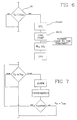
- the controller could either assign as total treatment time the maximum treatment time and then warn the operator that the prescribed dialysis dose will not be fulfilled or put the machine in bypass mode and ask for intervention of an operator. Notice that in some circumstances the presence of bubbles in the dialysis line or other factors degrade the performances of the treatment unit, which can recover however its normal properties upon appropriate corrections are carried out. If the operator action is positive then the calculation of the estimated remaining or total treatment time is repeated. If again the problem persists no further intervention is requested, the machine is put in permanent bypass mode (lines 11 and 12 connected bypassing second compartment 5) and an alarm given.
Landscapes
- Health & Medical Sciences (AREA)
- Heart & Thoracic Surgery (AREA)
- Urology & Nephrology (AREA)
- Hematology (AREA)
- Animal Behavior & Ethology (AREA)
- Engineering & Computer Science (AREA)
- Anesthesiology (AREA)
- Biomedical Technology (AREA)
- Emergency Medicine (AREA)
- Life Sciences & Earth Sciences (AREA)
- Vascular Medicine (AREA)
- General Health & Medical Sciences (AREA)
- Public Health (AREA)
- Veterinary Medicine (AREA)
- External Artificial Organs (AREA)
- Laser Surgery Devices (AREA)
- Surgical Instruments (AREA)
Abstract
Description
- The present invention relates to a blood treatment equipment comprising a control apparatus.
- More particularly, the invention is concerned with an apparatus, such as a programmable computer, capable of operating on a blood treatment equipment such as an hemodialysis or other blood treatment equipment; the programmable controller is adapted to receive entries of prescribed and measured information and to generate one or more output signals in response thereto. In general the output signals are employed to control a variable operation performed by the blood treatment equipment and hence automatically perform treatment procedure control methods.
- It is known in the art of hemodialysis and other blood treatment machines using measured values of certain parameters in order to control the working of the machine.
- For instance,
EP097366 US 4508622 both disclose a device provided with twoconductivity cells - In Gambro
EP0330892 , it is of advantage to employ measured values of a patient's conditional values to control functional aspects of hemodialysis equipments. In this fashion, the hemodialysis equipment may be controlled dependently of specific treatment requirements of a patient. In particular, this reference teaches to determine the concentration for a certain solute in patient's blood and other important parameters as actual clearance (indicated herein as K in ml/min) or dialysance values (expressed herein as D in ml/min). If for instance the system ofEP0330892 is adapted for determining sodium concentration or conductivity of patient's blood, the dialysis liquid concentration can be controlled in order to bring about an equilibrium between the conductivities of blood and dialysis liquid, thereby obtaining a control adapted to the individual which should provide comfort for the patient. - It is also known from
EP0532433 a blood treatment device able to detect actual sodium dialysance and then derive urea clearance by extrapolation. Such a calculated urea clearance is then compared with a desired urea clearance value and in case of need the flow rate of the dialysis pump or of the blood pump, or the treatment time are changed. In case treatment time is changed also the UF rate of the ultrafiltration pump is modified. - On the other hand during the last twenty years a specific index, the KT/V index, has been regarded as particularly indicative of the dialysis treatment. More in detail Keshaviah and Collins (Keshaviah P, Collins A: Rapid high-efficency bicarbonate hemodialysis, Trans Am Soc Artif Intern Organs 32: 17, 1986) reported in a well documented and well designed study on short dialysis, using the KTN index as a parameter of dialysis adequacy. This index, introduced in 1985 by Gotch and Sargent (Gotch F, Sargent JA: A mechanistic analysis of the National Cooperative Dialysis Study (NCDS). Kidney Int. 28: 526, 1985) is calculated as the product of the urea clearance (K, ml/min) of the dialyser and duration of the dialysis session (T, min), divided by the distribution volume of urea (V ml). Gotch and Sargent analysed the data of the large scale National Cooperative Dialysis Study (NCDS) in the US and determined that a KTN value of 0.9-1.0 constitutes adequate dialysis therapy. Values less than 0.8 are associated with a high probability of therapy failure. Keshaviah and Collins (Keshaviah P, Collins A: Rapid high-efficency bicarbonate hemodialysis, Trans Am Soc Artif Intern Organs 32: 17, 1986) also demonstrated that short and rapid dialysis treatment is well tolerated when acetate is replaced by bicarbonate and is not associated with increased mortality and morbidity if therapy is prescribed keeping KTN greater than 1.
- In view of the above works, the value D or K for a certain solute (Notice again that Durea=Kurea) have been employed to determine value K*Ti, herein indicated as dialysis dose achieved after time Ti.
- The approach presently followed in the blood treatment machines available on the marketplace is to obtain a measure of and to provide information related to a total dialysis dosage K*T value delivered as time progresses during a hemodialysis treatment procedure. This measure and the information provided is essentially based on parameters including:
- a prescribed duration of the treatment procedure,
- the blood flow rate,
- the choice of the hemodialyser
- A combination of above parameters is employed to obtain a measure of the total dialysis dosage value K*Tt delivered as an integral of mean measured instantaneous clearance values measured after determined time increments, the dialysance of the chosen dialyser (which is an in vitro clearance value) and the effective treatment time. The effective treatment time is the time during which diffusive (and generally also convective) transfer of blood solutes across a semi-permeable membrane of a hemodialyser takes place.
- The above procedure basically enables a measure to be made of the K*T value delivered to a patient during a hemodialysis treatment procedure.
- At the end of the treatment which normally lasts a prefixed total time Ttot, the machine provides the user with the value of K*Ttot and with the value K*Ttot/ V.
- This procedure, however, suffers from a number of drawbacks. Specifically, such factors as blood flow rate and effective treatment time, which are relevant to clearance, are prone to change or are difficult to follow during a hemodialysis treatment procedure. Furthermore, the dialysance or clearance capacity of hemodialyser products can change significantly during a hemodialysis treatment procedure time. Present day hemodialysis monitoring equipment and hemodialysis procedure methods may comprise means for assessing or measuring dialysis dosages delivered to a patient over determined time increments, but no means are available for controlling the dialysis dosage value actually delivered to the patient, on an ongoing bases during treatment, and for carrying out actions on the dialysis machine working parameters as a function of the detected dialysis dosage delivered to the patient.
- Document
EP 0 495 412 relates to the field of hemodialysis and the fact that many patients may not receive the prescribed dialysis dose Kt/V (urea), K being the clearance of urea by the dialyser, t the time and V the volume of distribution of urea. - This document describes a dialysis method providing dialysis dose by predicting a time end point for the dialysis. In this way, the dialysis dose of urea is selected by the physician, then the urea concentration is measured initially, and the end point prediction is based upon the preferred post-dialysis urea concentration and measured urea concentration values. Those data are compared, and if appropriate, dialysis should be terminated. In the event the comparison reveals that further dialysis is appropriate, a revised time end-point may be calculated.
- The document
WO98/55166 - So the two latest documents describe a method which measures one or more parameters during the treatment to calculate the effective dialysis dose in order to compare it with the prescribed dialysis dose.
- It Is an overall objective of the present invention to secure an ongoing control over the actual total dialysis dosage delivered to a patient.
- It is another object of the invention to control some parameters of a blood treatment machine as a function of the values of the dialysis dose measured in the course of the treatment.
- Furthermore, it an object of the invention to provide a control apparatus and a blood treatment equipment able to coordinate achievement of the prescribed dialysis dose with substantially contemporaneous achievement of other prescription(s).
- A further object is to provide a system for synchronizing achievement of a prescribed dialysis dose, of a prescribed weight loss and of a further prescribed prescription, such as concentration of a certain substance in patient's blood. Another object of the invention is to offer a system, which is adapted to reduce, if possible, the treatment time while achieving the requested prescribed results at the end of the treatment.
- Moreover it is an object of the invention to provide a controller and an equipment using said controller able to display updated values for a number of parameters, on ongoing basis at regular intervals during treatment.
- The above and other objects are reached by an equipment according to one or more of the appended claims.
- The controller according to the invention Is adapted to receive one or more entries of measured information measured during the course of a treatment procedure, calculate from said measured information at least a significant parameter indicative of the progress of an extracorporeal blood treatment carried out by the equipment, compare said calculated significant parameter to at least a prescribed reference value for the same parameter, and to generate at least one output control signal responsive to said comparison for automatically controlling one or more operations performed by the equipment. The significant parameter can be one chosen in the group comprising:
- the actual dialysance DTi or clearance KTi of a blood treatment unit associated with the equipment for a specific solute after a time Ti elapsed from the beginning of the treatment;
- the concentration of a substance in the blood of a patient undergoing a treatment or the patient's plasmatic conductivity CpTi achieved at the elapsed time Ti;
- the dialysis dose K*TTi achieved at the elapsed time Ti;
- the weight loss WLTi achieved at the elapsed time Ti;
- a parameter proportional or known function of one or more of the above parameters.
- The controller is adapted for receiving measured information from a conductivity sensor operating downstream the treatment unit or from a concentration sensor, again operating downstream the treatment unit, calculates at regular time intervals the achieved value of dialysis dosage and regulates the removal rate from the second compartment in order to have achievement, at the end of the treatment, of both the total prescribed dialysis dosage value KTp and the prescribed total weight loss WLp.
- The removal rate can be controlled by changing the speed of an ultrafiltration pump or if the equipment does not include a pump devoted to ultrafiltration only, by changing the speed of a pump associated to the waste line at the output of the second compartment.
- The controller can be programmed for estimating at regular time intervals the remaining treatment procedure time Ttr or the total treatment time Ttot necessary for achieving the prescriptions.
- The controller can also be programmed for keeping said rate of fluid removal UFTi at time Ti substantially equal to the product of a factor R, determined by the ratio between WLp and KTp, by the instantaneous clearance KTi or instantaneous dialysance value DTi measured at treatment time Ti. In this case the controller synchronizes two prescriptions and ends the treatment at the prescribed values are reached with no need of calculating the remaining treatment time or the treatment time at each interval.
- Safety measures may be provided to avoid that the treatment time or the fluid removal from the second compartment fall outside prescribed ranges.
- Note that the prescribed reference value may comprise a patient blood conductivity or concentration target Cpend: in this case the controller is programmed for controlling the conductivity or concentration of the treatment liquid entering the second compartment as a function of a blood conductivity or concentration target Cpend. in order to have blood conductivity or concentration for a substance reaching said conductivity or concentration target Cpend on or before said estimated total treatment time Ttot.
- Alternatively the controller is programmed for controlling the conductivity or concentration of the treatment liquid entering the second compartment for reaching said conductivity or concentration target Cpend when another prescription is reached (for instance total prescribed weight loss or total prescribed dialysis dose), with no need of calculation of a remaining treatment time.
- According to a further aspect, the controller is associated with a display screen adapted to display at the time intervals Ti one or more of the values of the group comprising:
- remaining time Ttr,
- total treatment time Ttot,
- clearance of dialysance measurements at the elapsed time Ti,
- achieved dialysis dosage KTTi after Ti time,
- achieved weight loss WLTi after Ti time,
- achieved patient's conductivity after Ti time,
- prescribed value for more of the significant parameters,
- a value proportional to one or more of the above values.
- The invention furthermore concerns program storage means including a program for a programmable controller, the program when run by the controller programming the controller to carry out the steps disclosed in the claims.
- An important difference between the invention as described above and approaches followed in the past is that the treatment procedure time involved in the present invention need not be a prescribed time but may be a time which is dependent on achievement of a prescribed value. Thus, in accordance with the invention, the treatment time may be controlled by measured information which can be related to a measure of an effective clearance value of a substance (usually urea is the reference substance) measured after a determined time increment during a hemodialysis treatment procedure.
- Notice that clearance values are influenced by ultrafiltration, which leads to convective transfer of solutes in blood plasma across a semi-permeable membrane of a hemodialyser product into dialysis fluid. In practically all hemodialysis treatment procedures, ultrafiltration to achieve loss of excess fluid in the patient is required. The controller is therefore adapted to include or account for the convective clearance, which follows from ultrafiltration. Most preferably, therefore, the controller should be adapted to provide output information related to both the diffusive and convective clearance values or conveniently an integrated measure of these two values.
- The invention will be described with reference to the accompanying exemplary drawing tables, wherein:
-
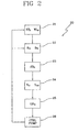
Fig 1 is a schematic drawing of hemodialysis equipment associated with a controller according to the invention; -
Fig 2 is a flow diagram showing the working principle of a controller according to a first embodiment of the invention; -
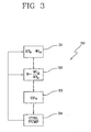
Fig 3 is a flow diagram showing the working principle of a controller according to a second embodiment of the invention; -
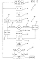
Fig 4 is a flow diagram showing the working principle of a controller according to a third embodiment of the invention; -
Fig 5 is a flow diagram showing the working principle of a controller according to a fourth embodiment of the invention; -
Fig 6 and 7 are flow diagrams of routines, which can be executed by the controller of the invention as part of its working principle. -
Fig 8 schematically shows a display screen that would be associated with the controller and equipment of the invention. - Specific embodiments of a blood treatment equipment, associated with or comprising a controller according to the invention, are described below. For the purpose of this description reference is made to a specific blood treatment equipment, namely a dialysis equipment. However the invention is not limited to such equipment and can be used in conjunction to other kinds of blood treatment machines. With reference to specification, including the accompanying schematic drawings and the claims, the symbols below will have the meanings identified as follows:
- Ttot = total treatment time
- Ti= elapsed treatment time, i.e. effective treatment time elapsed from the beginning of the treatment session
- Ttr= remaining treatment time
- Tmax= maximum treatment time
- Tmin= minimum treatment time
- Da= average dialysance
- DTi= actual dialysance at time Ti
- Ka= average clearance
- KTi= actual clearance at time Ti
- KT= dialysis dosage value
- KTp= prescribed dialysis dosage value
- KTTi= integrated dialysis dosage value at time Ti
- WL= weight loss
- WLp= prescribed weight loss
- WLTi= weight loss at time Ti
- UF= fluid removal rate from the second compartment of the treatment unit
- UFTi= fluid removal rate from the second compartment of the treatment unit at time Ti
- Referring now to
Figure 1 schematic drawing,reference numeral 1 refers generally to a blood treatment equipment, such as for instance hemodialysis equipment, comprising or associated with acontroller 2, for instance a programmable controller. The equipment as shown is connected to ablood treatment unit 3, such as a hemodialyser, comprising a first orblood compartment 4 and a second ordialysate compartment 5 divided by asemi-permeable membrane 6. Ablood pump 7 is provided upstream of the hemodialyzer for pumping blood from a patient along bloodarterial line 8 into the blood compartment and out from the blood compartment along bloodvenous line 9 todrip chamber 10 and back to the patient (not shown). Of course the position and number of blood pumps and the specific treatment unit indicated in the embodiment offig.1 are for exemplifying purpose only and are not intended to limit the scope of the invention. - Dialysate, coming for instance from a
dialysate preparation section 16, is conveyed into thedialysate compartment 5 alongdialysate inlet line 11 and out from the dialysate compartment alongdialysate outlet line 12 in a direction counter-current to blood flow in the hemodialyzer. A fluid balancing system is responsible of controlling the amount of fluid entering the second compartment and the amount of fluid exiting the second compartment so as to create a desired weight loss rate during treatment. For instance, the balancing system may be associated to a variablespeed ultrafiltration pump 13 operating on anultrafiltration line 13a branching offline 12 and provided for pumping ultrafiltrate from blood compartment across the semi-permeable membrane into the dialysate chamber and out from thedialysate outlet line 12. The balancing system can comprise conventional means,e.g. flow meters hemodialyzer product 3 in the way shown infigure 1 . The flow meters are connected tocontroller 2 so that the controller is able to act at least on the ultrafiltration pump and on the waste pump 12a to keep the flow rate of the fresh dialysis liquid measured byflow meter 14 equal to the used liquid flow rate measured byflow meter 15. As theultrafiltration pump 13 branching offconduit 12 operates upstream theflowmeter 15,such pump 13 flow rate defines the weight loss rate. Other balancing systems may comprise controlling volumes and/or weights of dialysate delivered to and withdrawn from the dialysate compartment. An infusion line may also be provided with (not shown in the appended drawing tables) for injecting replacement fluid in the arterial and/or in thevenous line - It is clear for those skilled in the art that the present invention can be used in any kind of blood treatment machine, independently from the specific balancing system.
- Going now back to the detailed description of the embodiment of
figure 1 , theequipment 10 can be adapted to perform different treatments such as: - conventional hemodialysis, HD, where no infusion is present and dialysis liquid circulates in the second compartment of the dialyzer (
fig 1 ); - hemofiltration, HF, where no dialysis liquid is present while solutes and plasma water are pumped through
line 12 and substitution fluid (not shown) is infused in the extracorporeal circuit or directly into the patient; - hemodiafiltration, HDF, which is a combination of HD and HF;
- other blood treatments in case the treatment unit is correspondingly modified.
- After the above description of the general structure of
equipment 1, here below a more detailed analysis of thecontroller 2 will be provided. -
Controller 2 comprises at least a programmable microprocessor with associated memories and interfaces suitable to communicate with the components ofequipment 1. Of course the present invention controller could also comprise an analogical type calculator, though this embodiment is not felt to be the most appropriate in term of costs and flexibility. - The
controller 2 is adapted to receive one or more entries of measured information measured during the course of a treatment procedure. In the embodiments shown the measured information comprises the conductivity of the dialysis liquid or the concentration of the dialysis liquid for at least a substance, measured downstream thedialyzer 3, i.e. online 12. As shown infigure 1 the controller is connected with measuring means 18 for measuring the conductivity of the treatment liquid downstream the treatment unit. Alternatively the controller may be connected to means for measuring the concentration of a substance in the treatment liquid downstream the treatment unit. Since the measured information may also comprise the conductivity of the dialysis liquid or the concentration of the dialysis liquid for at least a substance, measured upstream thedialyzer 3, i.e. online 11, theequipment 1 offigure 1 also includes measuring means 17 for measuring at least one of the conductivity of the treatment liquid upstream the treatment unit, or of the concentration of a substance in the treatment liquid upstream the treatment unit. The measurements carried out by the measuring means 17 operating upstream the treatment unit could be substituted by set or known values of conductivity or concentration. Notice that if the measured information is the urea concentration, it is not even necessary to carry out a measurement upstream as urea is absent from fresh dialysis liquid. - In case the measuring means are devoted to measure conductivity, then each measuring means 17, 18 comprises at least a conductivity cell. If the measuring means are devoted to measure an ion's concentration then said means comprises an ion selective sensor or a urea sensor (notice again that in case of measure of a quantity absent in fresh dialysis liquid -as urea - then there is no need to use a sensor on line 11).
- The
controller 1 is then programmed to calculate from the measured information (for instance from the value of the conductivity upstream and downstream the treatment unit) a value of at least a significant parameter indicative of the progress of an extracorporeal blood treatment carried out by the equipment. - According to the invention the significant parameter is one chosen in the group comprising:
- the actual dialysance DTi or clearance KTi of a blood treatment unit associated with the equipment for a specific solute after a time Ti elapsed from the beginning of the treatment;
- the concentration of a substance in the blood of a patient undergoing a treatment or the patient's plasmatic conductivity CpTi, achieved at the elapsed time Ti;
- the dialysis dose K*TTi achieved at the elapsed time Ti;
- the weight loss WLTi achieved at the elapsed time Ti;
- a parameter proportional or known function of one or more of the above parameters.
- Finally, the controller is adapted to compare said calculated significant parameter to at least a prescribed reference value for the same parameter, and to generate at least one output control signal responsive to said comparison for automatically controlling one or more operations performed by the equipment.
- For instance, the
controller 1 after having compared the calculated value of one or more significant parameters with the corresponding reference value for the same parameter may generate the output control signal responsive to said comparison for automatically controlling a fluid removal rate from said second compartment. Note that the measurement of the measured information, the calculation of the significant parameter(s), and the comparison with the respective reference value are done during the treatment (or at least during an effective portion of the treatment) on an ongoing basis, at regular time intervals, as it will be described in detail here below with reference to the embodiments shown in the drawing tables. The way that is felt to be the easiest for implementing the invention provides that the time intervals are indeed constant and prefixed, for instance equal to 15 minutes each. However, the invention can be implemented also using regular but not constant time intervals: i.e. time intervals following a specified rule or rules, which the controller should know or made aware of. - In a first embodiment, the
controller 2 is programmed to carry out the steps shown infigure 2 . - After having started the treatment, the controller waits for a prefixed time, for
instance figure 2 ,loop cycle 20, which is then repeated at each successive time interval. More in detail, according to this embodiment, the controller is programmed for determining the estimated remaining treatment procedure time Ttr and/or the estimated total treatment time TTot as a function of a calculated value of a significant parameter at time Ti. In other words the controller is able to modify the duration of the treatment if certain actual values of parameters deemed to be significant change during treatment. - In particular, the controller according to the first embodiment receives (as a
first step 21 of the loop cycle 20) the prescribed values for the dialysis dosage KTp and for the total weight loss WLp to be achieved at the end of the treatment. - Then, as
second step 22, determines the instantaneous clearance KTi or dialysance value DTi corresponding to the conductivity or concentration measurements at treatment time Ti. Then, the controller calculates the effective dialysis dosage KTTi achieved at time Ti (step 23). Once calculated KTTi, the controller proceeds withstep 24 for estimating the remaining treatment procedure time Ttr as a function of said total dialysis dosage value KTp, of the effective total dialysis dosage KTTi achieved by time Ti, and of the instantaneous clearance KTi or dialysance value DTi measured at treatment time Ti. As an alternative or in conjunction with the determination of the estimated remaining treatment time, thecontroller 2 is programmed for determining the estimated value of the total treatment time Ttot. The estimated value of the total treatment time can be calculated for instance as a function of said total dialysis dosage value KTp, of the effective total dialysis dosage KTi achieved by time Ti, and of the elapsed treatment time Ti. - Alternatively said controller can calculate the estimated total treatment time Ttot as sum of the elapsed treatment time Ti and of the estimated value of the remaining treatment procedure time Ttr.
- Once the estimated remaining treatment time or the estimated total treatment time are know at the instant Ti, the controller proceeds with
step 25 determining an actual measured total weight loss WLTi achieved by time Ti, and setting the fluid removal rate UF from said second compartment for achieving the prescribed total weight loss WLp, substantially at the same time as the prescribed total dialysis dosage value KTp is achieved. - Notice that the control on the fluid rate removal can also be done in such a way as to achieve the prescribed total weight loss some minutes before the estimated total treatment time, which as explained derives from the calculation of the actual dialysis dosage achieved at time Ti.
- Once corrected, if necessary (there might be the case where the flow rate extracted from the second compartment is already well tuned), the loop ends and the controller repeats the loop starting from
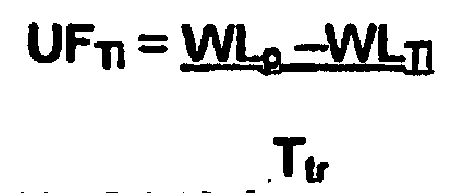
step 21 or fromstep 22 at the successive time interval, i.e. after a time which can be prefixed or calculated by the controller. In the case offigure 2 the time interval is equal to15 minutes. - Going in further detail, notice that the controller, which is programmed for controlling, on an ongoing basis, the fluid removal rate as a function of the estimated remaining treatment procedure time Ttr or of estimated total treatment time Ttot, sets the fluid removal rate UFTi at time Ti equal to the prescribed total weight loss WLp less the measured weight loss WLTi at time Ti, divided by the estimated remaining treatment time Ttr, according to the formula:

- Alternatively, the controller can be programmed for setting of the fluid removal rate UFTi at time Ti equal to the prescribed total weight loss WLp less the measured weight loss WLTi at time Ti, divided by a difference between the estimated total treatment time Ttot and the elapsed treatment time Tt according to the formula:

- As explained, the controller is programmed for recalculating and updating at regular time intervals during treatment the estimated total treatment time Ttot and/or the estimated remaining treatment time Ttr, on the basis of the value of instantaneous clearance KTi or dialysance DTi measured at the time Ti. As an alternative for determining the estimated total treatment time Ttot and/or the estimated remaining treatment time Ttr, at instant Ti, the controller could be programmed for using recent values of clearance KTi-k or dialysance DTi-k (i.e. values determined at one or more time intervals before Ti).
- In order to calculate dialysance and or clearance values during treatment any known method could be suitable. A know method provides that the instantaneous clearance value KTi or instantaneous dialysance value DTi is determined at treatment time Ti, by means of the following sub-steps:
- sending at least a first liquid through the second compartment of the treatment unit,
- sending at least a second liquid through the second compartment of the treatment unit, the second liquid having conductivity or concentration for at least a solute different from that of the first liquid
- measuring the conductivity or concentration values of said substance in the treatment liquid downstream the treatment unit at least for both said first and for said second liquid,
- calculating the instantaneous clearance KTi or instantaneous dialysance value DTi at least as a function of said measured conductivity or concentration values.
- Further details of the above method and variants thereof are described in detail in the following publications, which are incorporated herein by reference:
- Each of the above references describes an alternative way for in vivo determination of the actual dialysance, blood sodium concentration and dialysis dose. Note that any method able to determine one or more of the above significant parameters can be used for the purpose of the present invention. Referring by way of non-limiting example to a first known method for determining the concentration of a substance in blood and/or the actual dialysance for said substance (described in detail in
EP 0547025B1 ), at least two liquids differing for their respective concentration of said specific substance are sequentially circulated through thedialysate compartment 5. The first liquid can be the dialysis liquid at its normal prescribed value of concentration for the substance and the second liquid can be obtained by introducing a step or a change in the concentration of said substance at the dialyzer inlet. The step or the change has to be in someway known or measurable. Then the conductivity or concentration of the substance are measured for the first ad second liquid both upstream and downstream of the dialyzer. Note that the upstream measurements can be substituted by set reference values. Notice in this respect that if the substance is a ionic substance, then the concentration of the substance influences the conductivity of the dialysis liquid; in particular considering that conductivity is largely influenced by the concentration of sodium ions, than measure/calculation of conductivity values gives an indication of sodium concentration in blood and in the dialysis liquid. As conductivity sensors are much more convenient and easy to use than ion selective sensors for directly detecting the concentration of an electrolyte in a liquid flow, conductivity measurements are preferably used. Then by applying the following formula cited inEP 0547025B1 for the two dialysis liquids it is possible to determine the unknowns D and Cbin (no ultrafiltration and neglecting the so-called Donnan effect):
- Wherein:
- Cdout is the conductivity or concentration of sodium in used dialysis liquid
- Cdin is the conductivity or concentration of sodium in fresh dialysis liquid
- Cbin is the concentration of sodium in untreated blood
- Qd is the dialysis liquid flow
- DTt is the dialysance of the membrane for the solute sodium at time Tt (or urea clearance: notice that the size of the urea molecule being the
- same as the size of the sodium molecule, the capacity for these two molecules to pass through the same predetermined membrane is consequently the same. Therefore we can establish for a same membrane, the following equation: Dsodium = Kurea ; so detection of sodium dialysance gives clearance).
- Referring to the embodiment of
figure 1 , conductivity orsensors dialysate compartment 5 alongdialysate inlet line 11. In detail,conductivity sensor 17 provides upstream dialysate conductivity measures C1in, C2in relating to the conductivity of the first and second liquid upstream the dialyzer, whileconductivity sensor 18 measures the conductivities C1out, C2out of the first and second dialysis liquid flowing fromdialysate compartment 5 alongdialysate outlet line 12. The measures of conductivity (as intermittently influenced by intermittently introducing small boluses of higher or lower concentration dialysate solutions into the dialysate inlet line) are employed to determine with the above formula instantaneous sodium dialysance values (and therefore instantaneous urea clearance values KTi) at any point in time Ti during a hemodialysis treatment procedure or after determined time increments so that a dialysis dosage K TTi, delivered at time Ti, may be determined. The above equation can be written for the two dialysis liquids circulated through the dialyzer so that the two unknowns DTi and Cbini can be determined. Referring again to the drawings, the periodically measured conductivity values Cd1in, Cd2in and Cd10ut, Cd2out (1 and 2 referring to the first and second liquid respectively) are entered into the controller vialines - As mentioned the total dialysis dosage delivered up to a certain time interval is calculated and updated at each interval as function of KTi or Dti values determined with any suitable method. In detail notice that the controller can be programmed to determine the effective total dialysis dosage KTTi value, which has been delivered at the determined effective treatment time Ti, as an integration over time of effective instantaneous clearance KTi or instantaneous dialysance DTi values determined at the various regular time intervals Ti. Alternatively, the effective total dialysis dosage KTi value, which has been delivered at the effective treatment time Ti, could be calculated as the product of the treatment time Ti by a mean value of effective instantaneous clearance KTi or of instantaneous dialysance DTi values determined at the various regular time intervals Ti. Of course other suitable methods could be devised.
-
Figure 3 shows the steps, which a second embodiment of thecontroller 2 is programmed to carry out. - After having started the treatment, the controller waits for a prefixed time, for
instance loop cycle 30 shown infigure 3 ;loop cycle 30 is then repeated at each successive time interval. More in detail, according to this embodiment, the controller is not programmed for determining the estimated remaining treatment procedure time Ttr and/or the estimated total treatment time TTot, and as a matter of fact could be unaware of the actual duration of the treatment. The aim of the controller according to this second embodiment is to receive the prescribed parameters, i.e. the total clearance dosage value KTp to be achieved at the end of the treatment (step 31), and a prescribed total weight loss WLp to be achieved at the end of the treatment (step 31), and to synchronize achievement of both said parameters. - In detail the controller is programmed for determining a prescribed rate R by dividing said total weight loss WLp to be achieved at the end of the treatment by said total dialysis dose value KTp to be achieved at the end of the treatment, as shown in
step 32. - Then, in
steps - The loop is then concluded and the controller, as for the embodiment of
figure 2 , waits a time interval before stating againloop 30 from thestep 31 or directly fromstep 32, if no new prescribed values shall be considered. - Notice that the instantaneous clearance KTi or instantaneous dialysance value DTi measured at treatment time Ti can be determined as for the embodiment of
figure 2 . - In
figure 4 a further embodiment of the program steps to be followed by acontroller 2 according to the present invention is shown. The philosophy of thecontrol loop 40 offigure 4 is similar to the one of figure 20 with some further features added. - After having started the treatment, the controller waits for a prefixed time, for
instance figure 4 ,loop cycle 40, which is then repeated at each successive time interval. More in detail, according to this embodiment, the controller is programmed for determining the estimated remaining treatment procedure time Ttr and/or the estimated total treatment time TTot as a function of a calculated value of a significant parameter at time Ti. In other words the controller is able to modify the duration of the treatment if certain actual values of parameters deemed to be significant change during treatment. - In particular, the controller according to the first embodiment receives (as a
first step 41 of the loop cycle 40) the prescribed values for the dialysis dosage KTp and for the total weight loss WLp to be achieved at the end of the treatment, as well as prescribed values for a minimum acceptable treatment time Tmin and for a maximum acceptable treatment time Tmax. - Then, as
second step 42, determines the instantaneous clearance KTi or dialysance value DTi corresponding to the conductivity or concentration measurements at treatment time Ti. Then, the controller calculates the effective dialysis dosage KTTi achieved at time Ti (step 43). Once calculated KTTi, the controller proceeds withstep 44 for estimating the remaining treatment procedure time Ttr as a function of said total dialysis dosage value KTp, of the effective total dialysis dosage KTTi achieved by time Ti, and of the instantaneous clearance KTi or dialysance value DTi measured at treatment time Ti. As an alternative or in conjunction with the determination of the estimated remaining treatment time, thecontroller 2 is programmed for determining the estimated value of the total treatment time Ttot. The estimated value of the total treatment time can be calculated for instance as a function of said total dialysis dosage value KTp, of the effective total dialysis dosage KTi achieved by time Ti, and of the elapsed treatment time Ti. - Alternatively said controller can calculate the estimated total treatment time Ttot as sum of the elapsed treatment time Ti and of the estimated value of the remaining treatment procedure time Ttr.
- The controller is then programmed to carry out a sequence of operations globally indicated with 45 in
figure 4 and aiming to check whether or not the estimated values of Ttr or of Ttot are within the prescribed ranges. - In detail, said controller, at each time interval, is programmed for executing the following sub-steps of step 45:
- sub-step 46: comparing the sum Ti + Ttr with a minimum treatment time Tmin and with a maximum treatment time Tmax
- sub-step 47: setting a total treatment time Ttot equal to the minimum treatment time Tmin, if said sum is less then the minimum treatment time Tmin,
- sub-step 48: setting a total treatment time Ttot equal to the maximum treatment time Tmax, if said sum is more then the minimum treatment time Tmax,
- sub-step 49: setting a total treatment time Ttot equal to said sum if the sum is neither less then the minimum treatment time Tmin nor more then the minimum treatment time Tmax
- Once the total treatment time is known at the instant Ti, the controller proceeds with
step 45 determining an actual measured total weight loss WLTi achieved by time Ti, and setting the fluid removal rate UF from said second compartment for achieving the prescribed total weight loss WLp, substantially at the end of said treatment time Ttot. Notice that if the controller determines instep 46 that the remaining treatment time is such that a superior time limit for the whole treatment Tmax cannot be fulfilled, the controller can activate analarm procedure 52 and ask for intervention of an operator. - If vice versa the remaining treatment time is acceptable, notice that the control on the fluid rate removal can also be done in such a way as to achieve the prescribed total weight loss some minutes before the estimated total treatment time, which as explained derives from the calculation of the actual dialysis dosage achieved at time Ti.
- Once corrected the fluid removal rate from the second compartment, if necessary (there might be the case where the flow rate extracted from the second compartment is already tuned), the loop ends and the controller repeats the loop starting from
step 41 or fromstep 42 at the successive time interval, i.e. after a time which can be prefixed or calculated by the controller .In the case offigure 4 the time interval is equal to15 minutes. - Going in further detail, notice that the controller, which is programmed for controlling, on an ongoing basis, the fluid removal rate as a function of the estimated remaining treatment procedure time Ttr or of estimated total treatment time Ttot, sets the fluid removal rate UFTi at time Ti equal to the prescribed total weight loss WLp less the measured weight loss WLTi at time Ti, divided by the estimated remaining treatment time Ttr, according to the formula:

- Alternatively, the controller can be programmed for setting of the fluid removal rate UFTi at time Ti equal to the prescribed total weight loss WLp less the measured weight loss WLTi at time Ti, divided by a difference between the estimated total treatment time Ttot and the elapsed treatment time Tt according to the formula:

- As explained, the controller is programmed for recalculating and updating at regular time intervals during treatment the estimated total treatment time Ttot and/or the estimated remaining treatment time Ttr, on the basis of the value of instantaneous clearance KTi or dialysance DTi measured at the time Ti. As an alternative for determining the estimated total treatment time Ttot and/or the estimated remaining treatment time Ttr, at instant Ti, the controller could be programmed for using recent values of clearance KTi-k or dialysance DTi-k (i.e. values determined at one or more time intervals before Ti).
- In order to calculate dialysance and or clearance values during treatment any known method could be suitable as for the embodiment of
figure 2 . - As mentioned the total dialysis dosage delivered up to a certain time interval is calculated and updated at each interval as a function of KTi or Dti values. In detail notice that the controller can be programmed to determine the effective total dialysis dosage KTTi value, which has been delivered at the determined effective treatment time Ti, as an integration over time of effective instantaneous clearance KTi or instantaneous dialysance DTi values determined at the various regular time intervals Ti. Alternatively, the effective total dialysis dosage KTi value, which has been delivered at the effective treatment time Ti, could be calculated as the product of the treatment time Ti by a mean value of effective instantaneous clearance KTi or of instantaneous dialysance DTi values determined at the various regular time intervals Ti. Of course other suitable methods could be devised.
- In
figure 5 a variant program loop is shown, which thecontroller 2 can be programmed to execute.Control loop 40 offigure 5 is almost identical to theloop 40 offigure 4 and will not be described again in detail: the same reference numerals being used to identify corresponding features or steps. - As in the embodiment of
figure 4 , after having started the treatment, the controller waits for a prefixed time, forinstance figure 5 , which is then repeated at each successive time interval. - More in detail, according to this embodiment, the controller is programmed for determining the estimated remaining treatment procedure time Ttr and/or the estimated total treatment time TTot as a function of a calculated value of a significant parameter at time Ti. In other words the controller is able to modify the duration of the treatment if certain actual values of parameters deemed to be significant change during treatment.
- Differently from the embodiment of
figure 4 , the controller programmed to execute the steps offigure 5 receives (as afirst step 41 of the loop cycle 40): - the prescribed values for the dialysis dosage KTp and for the total weight loss WLp to be achieved at the end of the treatment,
- prescribed values for a minimum acceptable treatment time Tmin and for a maximum acceptable treatment time Tmax,
- a patient blood conductivity or concentration target Cpend,
- the urea distribution volume V0 for the patient.
- As it will appear clear the
controller 2 of this embodiment is programmed not only for achieving the aims of the controller programmed according tofigure 4 steps, but also for controlling the conductivity or concentration of the treatment liquid entering the second compartment as a function of said blood conductivity or concentration target Cpend. - Indeed, in accordance with the embodiment of
figure 5 , the controller executes the sameidentical steps figure 4 and then, afterstep 51, is programmed for changing, if necessary, at each time interval, the conductivity or concentration of the treatment liquid entering the second compartment in order to have blood conductivity or concentration for a substance reaching said conductivity or concentration target Cpend on or before said estimated total treatment time Ttot (step 53 infigure 5 ). Notice thatstep 53 can equivalently be carried out beforesteps - The
step 53 of modifying of treatment liquid conductivity or concentration Cd comprises the following sub-steps: - i. Determining a calculated value Cdi of the conductivity or concentration for a substance Cd as a function of the interval target Cpi and of the measured instantaneous dialysance or clearance Di or Ki for time Ti,
- ii. Bringing the conductivity or concentration for a substance Cd of treatment liquid entering the second compartment to said calculated value Cdi
- In detail the determining step uses one of the following formulas wherein V0 represents the urea distribution volume for the patient:

- In the above formulas the interval target blood conductivity or concentration Cpi for the patient's blood relating to a time interval ti, according to the following steps:
- evaluating if the elapsed treatment time Ti is more or less of a prescribed value Tp,
- assigning as interval target blood Cpi = Cpend + A, wherein A is a positive value, if Ti less than Tp
- assigning as interval target blood Cpi = Cpend, if Ti more than or equal to Tp.
- After the detailed description concerning the embodiments of
figures 2 ,3 ,4 and5 , here below are disclosed further features of the invention which can be employed in any of the embodiments wherein an estimated total treatment time or an estimated remaining treatment time are being calculated in use by thecontroller 2. - In detail, as shown in
figure 6 , the controller is programmed to carry out anend treatment test 60 to check if the remaining treatment time Ttr is less than a prescribed value, forinstance 15 minutes. In the negative the cycle continues with no changes while in the affirmative the removal rate at time Ti is calculated and set for the last time (blocks 25, 26; 50, 51) and an output signal is sent to an output device, such asdisplay unit 19. - In
figure 7 an alarm procedure is shown, which could be activated in case the estimated treatment time is greater than the maximum acceptable treatment time. Indeed as shown infigure 4 the controller could either assign as total treatment time the maximum treatment time and then warn the operator that the prescribed dialysis dose will not be fulfilled or put the machine in bypass mode and ask for intervention of an operator. Notice that in some circumstances the presence of bubbles in the dialysis line or other factors degrade the performances of the treatment unit, which can recover however its normal properties upon appropriate corrections are carried out. If the operator action is positive then the calculation of the estimated remaining or total treatment time is repeated. If again the problem persists no further intervention is requested, the machine is put in permanent bypass mode (lines - Please also notice that in the embodiments shown the controller is programmed to generate a control signal (arrow 's' in
figure 1 ) to automatically control the fluid removal rate from said second compartment by controlling the variablespeed ultrafiltration pump 13. However the fluid removal rate from the second compartment could be controlled in a different way depending upon the hydraulic structure and configuration of the dialysis circuit. - The controller is also associated to display
unit 19 which can operate as alert device, and which can be activated if the expected treatment procedure time or remaining hemodialysis treatment time are not within a prefixed range. - The
display 19 is also adapted to display at the time intervals Ti one or more of the values of the group comprising: - remaining time Ttr,
- total treatment time Ttot,
- clearance of dialysance measurements at the elapsed time Ti,
- achieved dialysis dosage KTTi after Ti time,
- achieved weight loss WLTi after Ti time,
- achieved patient's conductivity after Ti time,
- prescribed value for more of the significant parameters,
- a value proportional to one or more of the above values.
- In
figure 8 an embodiment of adisplay unit 19 is shown. The display unit comprises threefields controller 2 to flash when specific events occur. First field can be for instance green and flashes when the prescribed value for one or more relevant parameter is or are reached. The second field can be for instance orange and controlled to flash when the patient is close to the treatment end (block 61). - The third field, for instance red, can be controlled to flash in case of an alarm condition, for instance when the prescribed value KTp cannot be reached within a maximum acceptable treatment time (block 52).
- The display unit can also comprise an
area 105 includingpictograms alphanumerical strings 106 relating to the above prescribed and achieved significant parameters. - In addition to what already described it is also convenient to shortly underline some further possible variants to the above-described embodiments. As already mentioned, the total treatment time Ttot or remaining treatment time Ttr at time Ti is regularly recalculated and updated at regular, for instance identical, time intervals during treatment, on the basis of the last or most recent instantaneous measured clearance or dialysance value DTi. As an alternative the remaining treatment time and therefore also the fluid removal rate from the second compartment at time Ti can be calculated as known functions of more then one measured clearance or dialysance values. Thus, any such changes in parameters which take place during a hemodialysis treatment procedure which may influence the dialysance or clearance of a hemodialyser product, such as blood flow rate, dialysis fluid flow rate, alterations in the permeability of the semi-permeable membrane of the hemodialyser product, will automatically be accounted for each time the treatment time is recalculated. This procedure of the invention accordingly provides a reliable means for securing a measure of the treatment time required to secure the prescribed dialysis dosage value KTp.
- It should also be borne in mind that it is one objective of the present invention to secure control over the actual total dialysis dosage delivered to a patient; this control can for example be achieved, in accordance with the invention, by computing a hemodialysis treatment procedure time as a function of calculated values related to one or more of the above identified significant parameters (such as an effective clearance or dialysis dosage value reached after at treatment time Ti); a basic component of such computation would comprise a determination of a treatment time as a function of such one or more calculated values. Thus, in this example, a computed total effective treatment time would need to be a function of one or more values KTt1, KTt2, KTt3,---, KTtn, calculated in vivo using any known method after determined time increments Δt = say 5 min. For practical reasons it may only be possible to obtain a first measured value after about say 15 min of effective treatment time. Presuming this to be the case, a reasonably accurate assessment of an initial clearance or dosage value KTti, which has been achieved during said 15 min initial treatment time can be obtained by assuming that the measured clearance value or dosage delivered, for example after a 5 min interval, will substantially equate with the clearance value delivered over the same time period before the first measurement is made. Successive measurements of clearance values would generally be at least fractionally different from one another in that these values are dependent on changes (usually lowering) of the clearance capacity of the dialyser product during a treatment procedure, changes of blood rate, possible recirculation of treated blood, presence of bubbles in the dialysis liquid, dialysis liquid flow rate, ulfrafiltration rate and other changes.
- Also notice that measurements of clearance values would only be made during effective treatment times, i.e. while blood and dialysis liquid are flowing through the hemodialyser product. The controller is accordingly programmed to initiate measurements only during effective treatment times and similarly only compute or integrate effective treatment times to arrive at a computed hemodialysis treatment procedure time during effective treatment times.
- It would be possible to compute a hemodialysis treatment procedure time as a function of measured values in various fashions, e.g. by reference of the difference between successive total dialysis dosage values to a reference difference value and to compute an increase or decrease in the treatment time proportional to deviations from the reference difference value. Such a procedure could for example be realised more readily if a standardised total clearance or dialysis dosage value is to be achieved.
- Finally, it is to be noted that the invention relates also to program storage means including a program for the
programmable controller 2; the program when executed by the controller programs the controller to perform the steps disclosed above and shown in the attached drawings. The program storage may comprise an optical data carrier and/or a magnetic data carrier and or a volatile memory support, which can be read or associated or put into communication with the controller for programming this latter.
Claims (42)
- A blood treatment equipment, said equipment comprising at least a treatment unit including a semipermeable membrane separating the treatment unit in a first compartment for the circulation of blood and in a second compartment for the circulation of a treatment liquid, and a controller adapted to:- receive one or more entries of measured information measured during the course of a treatment procedure,- calculate from said measured information a value of at least a significant parameter indicative of the progress of an extracorporeal blood treatment carried out by the equipment,- compare said calculated significant parameter to at least a prescribed reference value for the same parameter, the prescribed reference value comprising the total dialysis dosage value KTp to be achieved at the end of the treatment,- generate at least one output control signal responsive to said comparison for automatically controlling one or more operations performed by the equipment,said controller determining, at time intervals during treatmento an instantaneous clearance KTi or dialysance value DTi measured at treatment time Ti,o an effective total dialysis dosage KTTi value which has been delivered at the elapsed treatment time Tti ando at least one among an estimated remaining treatment procedure time Ttr and an estimated total treatment time Ttot required for achieving said prescribed total dialysis dosage value KTp, wherein the controller is adapted to generate said output control signal responsive to said comparison for automatically controlling a fluid removal rate from said second comportment.
- Equipment according to claim 1, wherein the significant parameter is one chosen in the group comprising:- the actual dialysance DTi or clearance KTi of a blood treatment unit associated with the equipment for a specific solute after a time Ti elapsed from the beginning of the treatment;- the concentration of a substance in the blood of a patient undergoing a treatment or the patient's plasmatic conductivity CpTi achieved at the elapsed time Ti;- the dialysis dose K*TTi achieved at the elapsed time Ti;- the weight loss WLTi achieved at the elapsed time Ti;- a parameter proportional or known function of one or more of the above parameters.
- Equipment according to claims 1 or 2, wherein said measured information is one chosen in the group comprising:- conductivity of the treatment liquid downstream the treatment unit;- concentration of a substance in the treatment liquid downstream the treatment unit.
- Equipment according to anyone of claims 1 to 5 wherein said controller is programmed for determining the estimated remaining treatment procedure time Ttr as a function of said total dialysis dosage value KTp, the effective total dialysis dosage KTTi achieved by time Ti, and of the instantaneous clearance KTi or dialysance value DTi measured at treatment time Ti.
- Equipment according to anyone of claims 1 to 3, wherein said controller is programmed for determining the estimated total treatment time Ttot as a function of said total dialysis dosage value KTp, of the effective total dialysis dosage KTi achieved by time Ti, and of the elapsed treatment time Ti.
- Equipment according to claim 4, wherein said controller, at each time interval, is programmed for updating the estimated total treatment time Ttot as sum of the elapsed treatment time Ti and of the estimated value of the remaining treatment procedure time Ttr.
- Equipment according to claim 4 or 5 wherein said prescribed parameter also comprises a prescribed total weight loss WLp to be achieved at the end of the treatment, said controller being programmed for performing the following further steps at time intervals during treatment:o determining of an actual measured total weight loss WLTi achieved by time Ti,o setting of fluid removal rate UF from said second compartment for achieving a prescribed total weight loss WLp substantially at the same time as the prescribed total dialysis dosage value KTp is achieved.
- Equipment according to claim 7, wherein it is programmed for controlling, on an ongoing basis, the fluid removal rate as a function of the estimated remaining treatment procedure time Ttr or of estimated total treatment time Ttot.
- Equipment according to claim 8, wherein said controlling comprises setting of the fluid removal rate UFTi at time Ti equal to the prescribed total weight loss WLp less the measured weight loss WLTi at time Ti, divided by the estimated remaining treatment time Ttr, according to the formula:
- Equipment according to claim 8, wherein said controlling step comprises setting of the fluid removal rate UFTi at time Ti equal to the prescribed total weight loss WLp less the measured weight loss WLTi at time Ti, divided by a difference between the estimated total treatment time Ttot and the elapsed treatment time Tt according to the formula:

- Equipment according to anyone of claims from 1 to 10, wherein the controller is programmed for recalculating and updating at regular time intervals during treatment the estimated total treatment time Ttot and/or the estimated remaining treatment time Ttr, on the basis of the most recent value or values of instantaneous clearance KTi or dialysance DTi.
- Equipment according to anyone of claims from 1 to 10, wherein it is programmed for recalculating and updating at regular time Intervals during treatment the effective total dialysis dosage KTTi value, which has been delivered at the elapsed effective treatment time Ti.
- Equipment according to claim 1, wherein the instantaneous clearance value KTi or instantaneous dialysance value DTi is determined at treatment time Ti, by means of the following sub-steps:- sending at least a first liquid through the second compartment of the treatment unit,- sending at least a second liquid through the second compartment of the treatment unit, the second liquid having conductivity or concentration for at least a solute different from that of the first liquid- measuring the conductivity or concentration values of said substance in the treatment liquid downstream the treatment unit at least for both said first and for said second liquid,- calculating the instantaneous clearance KTi or instantaneous dialysance value DTi at least as a function of said measured conductivity or concentration values.
- Equipment according to claim 1, wherein the effective total dialysis dosage KTTi value, which has been delivered at the determined effective treatment time Ti, is calculated as an integration over time of effective instantaneous clearance KTi or instantaneous dialysance DTi values determined at the various regular time intervals Ti.
- Equipment according to claim 1, wherein the effective total dialysis dosage KTi value, which has been delivered at the effective treatment time Ti, is calculated as the product of the treatment time Ti by a mean value of effective instantaneous clearance KTi or of instantaneous dialysance DTi values determined at the various regular time intervals Ti.
- Equipment according to claim 12, wherein said controller is programmed for controlling the rate of fluid removal from the second compartment of the blood treatment, said controlling comprising keeping said rate of fluid removal UFTi at time Ti substantially equal to the product of said prescribed rate R by the instantaneous clearance KTi or instantaneous dialysance value DTi measured at treatment time Ti.
- Equipment according to claim 1, wherein said controller, at each time interval, is programmed for:- calculating a sum of the elapsed treatment time Ti with the calculated value of the remaining treatment procedure time Ttr.- comparing said sum with a minimum treatment time Tmin and with a maximum treatment time Tmax- setting a total treatment time Ttot equal to the minimum treatment time Tmin, if said sum Is less then the minimum treatment time Tmin,- setting a total treatment time Ttot equal to the maximum treatment time Tmax, if said sum is more then the minimum treatment time Tmax- setting a total treatment time Ttot equal to said sum if the sum is neither less then the minimum treatment time Tmin nor more then the minimum treatment time Tmax.
- Equipment according to claim 17, wherein said prescribed parameter also comprises a prescribed total weight loss WLp to be achieved at the end of the treatment, said controller being programmed for performing the following further steps at time intervals during treatment:o determining of an actual measured total weight loss WLTi achieved by time Ti,o setting of fluid removal rate from said second compartment for achieving a prescribed total weight loss WLp at said total treatment time Ttot.
- Equipment according to claim 18, wherein the controller is programmed for controlling, on an ongoing basis, the fluid removal rate UFTi at time Ti as a function of the total treatment time Ttot by setting the UFTi fluid removal rate at time Ti equal to the prescribed total weight loss WLp less the measured weight loss WLTi at time Ti. divided by the difference between the calculated total treatment time Ttot and the elapsed treatment time Ti, according to the formula:

- Equipment according to claim 18, wherein the controller is programmed for recalculating and updating the total treatment time Ttot and/or the remaining treatment time Ttr at regular time intervals during treatment, on the basis of the last or most recent instantaneous measured value or values of clearance KTi or dialysance DTi.
- Equipment according to claim 18, wherein the controller is programmed for recalculating and updating at regular time intervals during treatment the effective total dialysis dosage KTTi value which has been delivered at the elapsed effective treatment time Ti.
- Equipment according to claim 18, wherein the effective total dialysis dosage KTi value, which has been delivered at the determined effective treatment time Ti, is calculated as an integration over time of effective instantaneous dialysis dosage values DTi determined at the various regular time intervals Ti.
- Equipment according to claim 1 or 17, wherein the prescribed reference value comprises a patient blood conductivity or concentration target Cpend, said controller being programmed for controlling the conductivity or concentration of the treatment liquid entering the second compartment as a function of said blood conductivity or concentration target Cpend.
- Equipment according to claim 1, wherein the prescribed reference value comprises a patient blood conductivity or concentration target Cpend to be achieved, said controller being programmed for changing, if necessary, at each time interval, the conductivity or concentration of the treatment liquid entering the second compartment in order to have blood conductivity or concentration for a substance reaching said conductivity or concentration target Cpend on or before said estimated total treatment time Ttot.
- Equipment according to claim 7, wherein the prescribed reference value comprises a patient blood conductivity or concentration target Cpend to be achieved, said controller being programmed for changing, if necessary, at each time interval, the conductivity or concentration of the treatment liquid entering the second compartment in order to have blood conductivity or concentration for a substance reaching said conductivity or concentration target Cpend on or before said estimated total treatment time Ttot
- Equipment according to anyone of claims from 1 to 22, wherein the prescribed reference value comprises a patient blood conductivity or concentration target Cpend to be achieved, said controller being programmed for performing the following steps at each time Interval ti during at least a part of said treatment:o determining an interval target blood conductivity or concentration Cpi for the patient's blood, relating to a elapsed time Tio modifying, if necessary, the conductivity or concentration for a substance Cd of treatment liquid entering the second compartment to have the patient plasmatic conductivity reaching the interval target Cpi.
- Equipment according to claim 26, wherein the said modifying of treatment liquid conductivity or concentration Cd comprises the following sub-steps:i. Determining a calculated value Cdi of the conductivity or concentration for a substance Cd as a function of the Interval target Cpi and of the measured instantaneous dialysance or clearance Di or Ki for time Ti,ii. Bringing the conductivity or concentration for a substance Cd of treatment liquid entering the second compartment to said calculated value Cdi
- Equipment according to claim 27, wherein the said determining step uses the following formula:
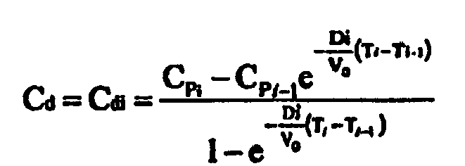
wherein Vo represents the urea distribution volume for the patient. - Equipment according to claim 27, wherein the said determining step uses the following formula:

- Equipment according to claim 26, wherein the controller is programmed for calculating said interval target blood conductivity or concentration Cpi for the patient's blood relating to a time interval ti, according to the following steps:- evaluating if the elapsed treatment time Ti is more or less of a prescribed value Tp,- assigning as interval target blood Cpi = Cpend + A, wherein A is a positive value, if Ti less than Tp- assigning as interval target blood Cpi = Cpend, if Ti more than or equal to Tp.
- Equipment according to claim 30, wherein the prescribed value Tp is less than Ttot.
- Equipment according to claim 31, wherein the prescribed value Tp is equal to Ttot reduced by one hour.
- Equipment according to claim 1, comprising measuring means connected to the controller for measuring at least one of:conductivity of the of the treatment liquid downstream the treatment unit; orconcentration of a substance in the treatment liquid downstream the treatment unit.
- Equipment according to claim 1, comprising measuring means for measuring at least one of:conductivity of the of the treatment liquid upstream the treatment unit; orconcentration of a substance in the treatment liquid upstream the treatment unit.
- Equipment according to claim 33, comprising measuring means for measuring comprises a conductivity cell or an ion selective sensor or a urea sensor, operating on a conduit downstream the treatment unit.
- Equipment according to claim 34, comprising measuring means for measuring comprises a conductivity cell or an ion selective sensor, operating on a conduit upstream the treatment unit.
- Equipment according to claim 1 also including entry means for entering prescribed reference value or values for the significant parameter or parameters.
- Equipment according to claim 1, comprising a variable speed ultrafiltration pump, in which the controller is programmed to generate a control signal to automatically control the fluid removal rate from said second compartment by controlling the variable speed ultrafiltration pump.
- Equipment according to claim 1, wherein the controller is associated with an alert device, and the controller is programmed to activate said alert device if the expected treatment procedure time or remaining hemodialysis treatment time are not within a prefixed range.
- Equipment according to claim 1, in which the controller is associated with a display screen adapted to display at the time intervals Ti one or more of the values of the group comprising:- remaining time Ttr,- total treatment time Ttot,- clearance of dialysance measurements at the elapsed time Ti,- achieved dialysis dosage KTTi after Ti time,- achieved weight loss WLTi after Ti time,- achieved patient's conductivity after Ti time,- prescribed value for more of the significant parameters,- a value proportional to one or more of the above values.
- Program storage means Including a program for a programmable controller of a blood treatment equipment according to claim 1, the program when run by the controller rendering the controller adapted to execute a method of automatically controlling one or more variable operations performed by the equipment comprising the steps of: receiving one or more entries of measured information measured during the course of a treatment procedure- calculating from said measured information a value of at least a significant parameter indicative of the progress of an extracorporeal blood treatment carried out by the equipment,- comparing said calculated significant parameter to at least a prescribed reference value for the same parameter, the prescribed reference value comprising the total dialysis dosage value KTp to be achieved at the end of the treatment,- generating at least one output control signal responsive to said comparison for automatically controlling one or more operations performed by the equipment,- determining, at time intervals during treatment:o an instantaneous clearance KTi or dialysance value DTi measured at treatment time Ti,o an effective total dialysis dosage KTTi value which has been delivered at the elapsed treatment time Ti, ando at least one among an estimated remaining treatment procedure time Ttr and an estimated total treatment time Ttot required for achievingsaid prescribed total dialysis dosage value KTp, - wherein the step of generating said output control signal responsive to said comparison is for automatically controlling a fluid removal rate from said second comportement.
- Program storage means according to claim 41 comprising an optical data carrier and/or a magnetic data carrier and or a volatile memory support.
Priority Applications (2)
| Application Number | Priority Date | Filing Date | Title |
|---|---|---|---|
| EP10007355.0A EP2243502B1 (en) | 2002-09-05 | 2003-09-04 | Control apparatus for a blood treatment equipment |
| EP03793964A EP1545652B1 (en) | 2002-09-05 | 2003-09-04 | Blood treatment equipment |
Applications Claiming Priority (4)
| Application Number | Priority Date | Filing Date | Title |
|---|---|---|---|
| EP02078806.3A EP1396274B2 (en) | 2002-09-05 | 2002-09-05 | Controller for a blood treatment equipment |
| EP02078806 | 2002-09-05 | ||
| PCT/IB2003/003745 WO2004022135A1 (en) | 2002-09-05 | 2003-09-04 | Sontrol apparatus and control method for a blood treatment equipment |
| EP03793964A EP1545652B1 (en) | 2002-09-05 | 2003-09-04 | Blood treatment equipment |
Related Child Applications (2)
| Application Number | Title | Priority Date | Filing Date |
|---|---|---|---|
| EP10007355.0A Division EP2243502B1 (en) | 2002-09-05 | 2003-09-04 | Control apparatus for a blood treatment equipment |
| EP10007355.0 Division-Into | 2010-07-15 |
Publications (2)
| Publication Number | Publication Date |
|---|---|
| EP1545652A1 EP1545652A1 (en) | 2005-06-29 |
| EP1545652B1 true EP1545652B1 (en) | 2013-01-09 |
Family
ID=31502807
Family Applications (3)
| Application Number | Title | Priority Date | Filing Date |
|---|---|---|---|
| EP02078806.3A Expired - Lifetime EP1396274B2 (en) | 2002-09-05 | 2002-09-05 | Controller for a blood treatment equipment |
| EP10007355.0A Expired - Lifetime EP2243502B1 (en) | 2002-09-05 | 2003-09-04 | Control apparatus for a blood treatment equipment |
| EP03793964A Expired - Lifetime EP1545652B1 (en) | 2002-09-05 | 2003-09-04 | Blood treatment equipment |
Family Applications Before (2)
| Application Number | Title | Priority Date | Filing Date |
|---|---|---|---|
| EP02078806.3A Expired - Lifetime EP1396274B2 (en) | 2002-09-05 | 2002-09-05 | Controller for a blood treatment equipment |
| EP10007355.0A Expired - Lifetime EP2243502B1 (en) | 2002-09-05 | 2003-09-04 | Control apparatus for a blood treatment equipment |
Country Status (11)
| Country | Link |
|---|---|
| US (2) | US8512564B2 (en) |
| EP (3) | EP1396274B2 (en) |
| JP (2) | JP4718178B2 (en) |
| KR (1) | KR100970414B1 (en) |
| CN (2) | CN100531810C (en) |
| AT (1) | ATE298595T1 (en) |
| AU (1) | AU2003255975B9 (en) |
| CA (1) | CA2496854C (en) |
| DE (2) | DE60204883T3 (en) |
| ES (3) | ES2245723T5 (en) |
| WO (1) | WO2004022135A1 (en) |
Cited By (34)
| Publication number | Priority date | Publication date | Assignee | Title |
|---|---|---|---|---|
| US9144640B2 (en) | 2013-02-02 | 2015-09-29 | Medtronic, Inc. | Sorbent cartridge configurations for improved dialysate regeneration |
| US9707328B2 (en) | 2013-01-09 | 2017-07-18 | Medtronic, Inc. | Sorbent cartridge to measure solute concentrations |
| US9713668B2 (en) | 2012-01-04 | 2017-07-25 | Medtronic, Inc. | Multi-staged filtration system for blood fluid removal |
| US9827361B2 (en) | 2013-02-02 | 2017-11-28 | Medtronic, Inc. | pH buffer measurement system for hemodialysis systems |
| US9884145B2 (en) | 2013-11-26 | 2018-02-06 | Medtronic, Inc. | Parallel modules for in-line recharging of sorbents using alternate duty cycles |
| US9895477B2 (en) | 2013-11-26 | 2018-02-20 | Medtronic, Inc. | Detachable module for recharging sorbent materials with optional bypass |
| US9943780B2 (en) | 2013-11-26 | 2018-04-17 | Medtronic, Inc. | Module for in-line recharging of sorbent materials with optional bypass |
| US10004839B2 (en) | 2013-11-26 | 2018-06-26 | Medtronic, Inc. | Multi-use sorbent cartridge |
| US10016553B2 (en) | 2014-06-24 | 2018-07-10 | Medtronic, Inc. | Replenishing urease in dialysis systems using a urease introducer |
| US10124274B2 (en) | 2014-06-24 | 2018-11-13 | Medtronic, Inc. | Replenishing urease in dialysis systems using urease pouches |
| US10172991B2 (en) | 2014-06-24 | 2019-01-08 | Medtronic, Inc. | Modular dialysate regeneration assembly |
| US10272363B2 (en) | 2014-06-24 | 2019-04-30 | Medtronic, Inc. | Urease introduction system for replenishing urease in a sorbent cartridge |
| US10343145B2 (en) | 2013-11-26 | 2019-07-09 | Medtronic, Inc. | Zirconium phosphate recharging method and apparatus |
| US10357757B2 (en) | 2014-06-24 | 2019-07-23 | Medtronic, Inc. | Stacked sorbent assembly |
| US10420872B2 (en) | 2014-12-10 | 2019-09-24 | Medtronic, Inc. | Degassing system for dialysis |
| US10532141B2 (en) | 2013-02-01 | 2020-01-14 | Medtronic, Inc. | Systems and methods for multifunctional volumetric fluid control |
| US10537875B2 (en) | 2013-11-26 | 2020-01-21 | Medtronic, Inc. | Precision recharging of sorbent materials using patient and session data |
| US10807068B2 (en) | 2014-06-24 | 2020-10-20 | Medtronic, Inc. | Sorbent pouch |
| US10874787B2 (en) | 2014-12-10 | 2020-12-29 | Medtronic, Inc. | Degassing system for dialysis |
| US10960381B2 (en) | 2017-06-15 | 2021-03-30 | Medtronic, Inc. | Zirconium phosphate disinfection recharging and conditioning |
| US10981148B2 (en) | 2016-11-29 | 2021-04-20 | Medtronic, Inc. | Zirconium oxide module conditioning |
| US11110215B2 (en) | 2018-02-23 | 2021-09-07 | Medtronic, Inc. | Degasser and vent manifolds for dialysis |
| US11154648B2 (en) | 2013-01-09 | 2021-10-26 | Medtronic, Inc. | Fluid circuits for sorbent cartridge with sensors |
| US11167070B2 (en) | 2017-01-30 | 2021-11-09 | Medtronic, Inc. | Ganged modular recharging system |
| US11213616B2 (en) | 2018-08-24 | 2022-01-04 | Medtronic, Inc. | Recharge solution for zirconium phosphate |
| US11278654B2 (en) | 2017-12-07 | 2022-03-22 | Medtronic, Inc. | Pneumatic manifold for a dialysis system |
| US11565029B2 (en) | 2013-01-09 | 2023-01-31 | Medtronic, Inc. | Sorbent cartridge with electrodes |
| US11786645B2 (en) | 2013-02-01 | 2023-10-17 | Mozarc Medical Us Llc | Fluid circuit for delivery of renal replacement therapies |
| US11857712B2 (en) | 2013-01-09 | 2024-01-02 | Mozarc Medical Us Llc | Recirculating dialysate fluid circuit for measurement of blood solute species |
| US12128165B2 (en) | 2020-04-27 | 2024-10-29 | Mozarc Medical Us Llc | Dual stage degasser |
| US12285552B2 (en) | 2018-08-14 | 2025-04-29 | Mozarc Medical Us Llc | Precision dialysis therapy based on sorbent effluent analysis |
| US12397093B2 (en) | 2021-05-18 | 2025-08-26 | Mozarc Medical Us Llc | Sorbent cartridge designs |
| US12472292B2 (en) | 2018-02-02 | 2025-11-18 | Mozarc Medical Us Llc | Sorbent manifold for a dialysis system |
| US12569601B2 (en) | 2021-04-07 | 2026-03-10 | Mozarc Medical Us Llc | Increased operational capabilities of a dialysis system |
Families Citing this family (73)
| Publication number | Priority date | Publication date | Assignee | Title |
|---|---|---|---|---|
| US7163520B2 (en) * | 2002-06-26 | 2007-01-16 | Chf Solutions, Inc. | Method and device for removal of radiocontrast media from blood |
| DE602005020455D1 (en) * | 2005-10-21 | 2010-05-20 | Bellco Srl | Dialysis machine with natural control |
| EP1872714B1 (en) * | 2006-06-28 | 2009-01-07 | F. Hoffmann-la Roche AG | Method for monitoring a system for the determination of analyte concentration in a body fluid |
| DE102006032926A1 (en) * | 2006-07-15 | 2008-01-17 | Fresenius Medical Care Deutschland Gmbh | Method and device for prescribing treatment parameters for extracorporeal dialysis treatments |
| CN102046222B (en) * | 2008-05-26 | 2014-02-19 | 甘布罗伦迪亚股份公司 | A hemodialysis or hemo(dia)filtration apparatus and a method for controlling a hemodialysis or hemo(dia)filtration apparatus |
| EP2163272B1 (en) * | 2008-09-15 | 2014-06-25 | B. Braun Avitum AG | Device to early predict the Kt/V parameter in kidney substitution treatments |
| WO2010108955A1 (en) * | 2009-03-24 | 2010-09-30 | Gambro Lundia Ab | Dialysis device |
| DE102009018649A1 (en) * | 2009-04-23 | 2010-10-28 | Fresenius Medical Care Deutschland Gmbh | Dialysis machine, method and apparatus for a dialysis machine |
| DE102009040104A1 (en) * | 2009-09-04 | 2011-03-10 | B. Braun Avitum Ag | Device for extracorporeal blood treatment |
| US8753515B2 (en) | 2009-12-05 | 2014-06-17 | Home Dialysis Plus, Ltd. | Dialysis system with ultrafiltration control |
| ES2802609T3 (en) * | 2010-04-16 | 2021-01-20 | Baxter Int | Prediction and optimization of therapy for renal failure hemotherapy, especially home hemodialysis |
| US8845570B2 (en) | 2010-04-16 | 2014-09-30 | Baxter International Inc. | Therapy prediction and optimization for renal failure blood therapy, especially home hemodialysis |
| US9132219B2 (en) | 2010-04-16 | 2015-09-15 | Baxter International Inc. | Therapy prediction and optimization of serum potassium for renal failure blood therapy, especially home hemodialysis |
| PL2380609T3 (en) * | 2010-04-22 | 2017-12-29 | Fresenius Medical Care Deutschland Gmbh | Devices and controller for controlling of a filtration rate |
| ES2853742T3 (en) | 2010-04-22 | 2021-09-17 | Fresenius Medical Care Deutschland Gmbh | Controller to control a filtration rate, appliances, devices and digital storage media |
| US8501009B2 (en) | 2010-06-07 | 2013-08-06 | State Of Oregon Acting By And Through The State Board Of Higher Education On Behalf Of Oregon State University | Fluid purification system |
| ES2424796T3 (en) * | 2010-07-08 | 2013-10-08 | Gambro Lundia Ab | Apparatus for controlling extracorporeal blood treatment in a medical device |
| WO2012038384A1 (en) | 2010-09-20 | 2012-03-29 | Gambro Lundia Ab | Obtaining control settings for a dialysis machine |
| PL2433662T3 (en) * | 2010-09-27 | 2014-10-31 | Gambro Lundia Ab | Apparatus for extracorporeal treatment of blood |
| ES2561461T3 (en) * | 2010-09-30 | 2016-02-26 | Gambro Lundia Ab | Apparatus for extracorporeal blood treatment |
| EP2465553A1 (en) | 2010-12-14 | 2012-06-20 | B. Braun Avitum AG | Extracorporeal blood treatment device |
| ES2445592T3 (en) | 2010-12-20 | 2014-03-04 | Gambro Lundia Ab | Method and system for providing priming and restitution fluids for extracorporeal blood treatment |
| ITMI20110442A1 (en) * | 2011-03-21 | 2012-09-22 | Gambro Lundia Ab | EQUIPMENT FOR EXTRACORPROUS TREATMENT OF BLOOD. |
| ITMI20110441A1 (en) * | 2011-03-21 | 2012-09-22 | Gambro Lundia Ab | EQUIPMENT FOR EXTRACORPROUS TREATMENT OF BLOOD. |
| US8945936B2 (en) | 2011-04-06 | 2015-02-03 | Fresenius Medical Care Holdings, Inc. | Measuring chemical properties of a sample fluid in dialysis systems |
| EP3165245B1 (en) | 2011-08-02 | 2019-02-20 | Medtronic, Inc. | Hemodialysis system having a flow path with a controlled compliant volume |
| WO2013025844A2 (en) * | 2011-08-16 | 2013-02-21 | Medtronic, Inc. | Modular hemodialysis system |
| US9155823B2 (en) * | 2011-08-22 | 2015-10-13 | Fresenius Medical Care Holdings, Inc. | Determining dialysis treatment effectiveness |
| ES2500966T3 (en) | 2011-08-30 | 2014-10-01 | Gambro Lundia Ab | Apparatus for extracorporeal blood treatment, and flow calculation process set in a medical device for delivery or collection of fluids |
| DE102011053200A1 (en) * | 2011-09-01 | 2013-03-07 | Fresenius Medical Care Deutschland Gmbh | Dialysate flow control |
| JP2014533133A (en) | 2011-10-07 | 2014-12-11 | ホーム・ダイアリシス・プラス・リミテッドHome DialysisPlus, Ltd. | Purification of heat exchange fluids for dialysis systems |
| ES2532081T3 (en) * | 2012-03-28 | 2015-03-24 | Gambro Lundia Ab | Device for extracorporeal blood treatment |
| EP2711036B1 (en) | 2012-09-21 | 2015-12-30 | Gambro Lundia AB | An apparatus control for extracorporeal blood treatment |
| EP2712638B1 (en) | 2012-09-28 | 2015-06-24 | Gambro Lundia AB | An apparatus and a method of controlling an extracorporeal blood treatment |
| EP2712639B1 (en) | 2012-09-28 | 2015-06-24 | Gambro Lundia AB | An apparatus for extracorporeal blood treatment and a control method therefor |
| EP3723041A1 (en) | 2012-10-24 | 2020-10-14 | CathWorks Ltd. | Automated measurement system and method for coronary artery disease scoring |
| US10210956B2 (en) | 2012-10-24 | 2019-02-19 | Cathworks Ltd. | Diagnostically useful results in real time |
| DE102012020945B4 (en) * | 2012-10-25 | 2019-10-10 | Fresenius Medical Care Deutschland Gmbh | Apparatus, system and method for monitoring, displaying and operating medical fluid management devices |
| US10543052B2 (en) | 2013-02-01 | 2020-01-28 | Medtronic, Inc. | Portable dialysis cabinet |
| US10850016B2 (en) | 2013-02-01 | 2020-12-01 | Medtronic, Inc. | Modular fluid therapy system having jumpered flow paths and systems and methods for cleaning and disinfection |
| EP3954298A3 (en) | 2013-10-24 | 2022-03-16 | Cathworks Ltd. | Vascular characteristic determination with correspondence modeling of a vascular tree |
| US20150314055A1 (en) | 2014-04-29 | 2015-11-05 | Michael Edward HOGARD | Dialysis system and methods |
| US10569000B2 (en) * | 2014-05-30 | 2020-02-25 | Fresenius Medical Care Holdings, Inc. | System for analyzing vascular refill during short-pulse ultrafiltration in hemodialysis |
| DE102014012423A1 (en) * | 2014-08-20 | 2016-02-25 | Fresenius Medical Care Deutschland Gmbh | Dialysis machine with the ability to determine a predialytic property in the blood of a dialysis patient |
| EP3018601B1 (en) | 2014-11-10 | 2021-06-23 | B. Braun Avitum AG | Blood purification device graphical user interface method |
| US9895479B2 (en) | 2014-12-10 | 2018-02-20 | Medtronic, Inc. | Water management system for use in dialysis |
| US10098993B2 (en) | 2014-12-10 | 2018-10-16 | Medtronic, Inc. | Sensing and storage system for fluid balance |
| US10406269B2 (en) | 2015-12-29 | 2019-09-10 | Fresenius Medical Care Holdings, Inc. | Electrical sensor for fluids |
| US10617809B2 (en) | 2015-12-29 | 2020-04-14 | Fresenius Medical Care Holdings, Inc. | Electrical sensor for fluids |
| JP7099963B2 (en) | 2016-05-16 | 2022-07-12 | キャスワークス リミテッド | How to select blood vessels from images |
| EP4300419A3 (en) | 2016-05-16 | 2024-04-03 | Cathworks Ltd. | System for vascular assessment |
| JP7025408B2 (en) | 2016-08-19 | 2022-02-24 | アウトセット・メディカル・インコーポレイテッド | Peritoneal dialysis system and method |
| CN106693096A (en) * | 2016-12-30 | 2017-05-24 | 北京迈淩医疗技术发展有限公司 | Hemodialysis device and method capable of online measuring urea clearance index |
| CN106902407B (en) * | 2017-02-22 | 2019-11-01 | 广州大学 | A kind of haemodialysis urea clearance on-line measuring device and method |
| JP6409095B1 (en) * | 2017-06-14 | 2018-10-17 | 日機装株式会社 | Blood purification system |
| JP6997582B2 (en) * | 2017-10-17 | 2022-01-17 | 日機装株式会社 | Blood purification device |
| ES3028957T3 (en) | 2018-08-23 | 2025-06-20 | Outset Medical Inc | Dialysis system and methods |
| DE102019101774A1 (en) | 2019-01-24 | 2020-07-30 | Fresenius Medical Care Deutschland Gmbh | Device for extracorporeal blood treatment |
| EP3693039B1 (en) * | 2019-02-11 | 2021-06-09 | Gambro Lundia AB | Apparatus for extracorporeal treatment of blood and method for determining a parameter indicative of the progress of an extracorporeal blood treatment |
| EP3948886B1 (en) | 2019-04-01 | 2025-10-29 | CathWorks Ltd. | Methods and apparatus for angiographic image selection |
| CA3133332A1 (en) | 2019-04-30 | 2020-11-05 | Dean Hu | Dialysis system and methods |
| US12039685B2 (en) | 2019-09-23 | 2024-07-16 | Cathworks Ltd. | Methods, apparatus, and system for synchronization between a three-dimensional vascular model and an imaging device |
| EP3991764B1 (en) | 2020-10-27 | 2024-03-06 | Bellco S.r.l. | Flowmeter for proportioning water in dialysis system |
| US12318528B2 (en) | 2020-10-30 | 2025-06-03 | Mozarc Medical Us Llc | Variable orifice fistula graft |
| ES3007240T3 (en) | 2020-10-30 | 2025-03-19 | Bellco Srl | Dialysis cassette with pump features |
| EP4008376A1 (en) | 2020-12-03 | 2022-06-08 | Medtronic, Inc. | Flexible tube routing accessory for peritoneal dialysis system |
| US12315076B1 (en) | 2021-09-22 | 2025-05-27 | Cathworks Ltd. | Four-dimensional motion analysis of a patient's coronary arteries and myocardial wall |
| DE102021126681A1 (en) * | 2021-10-14 | 2023-05-25 | Fresenius Medical Care Deutschland Gmbh | Method and device for monitoring blood purification with an extracorporeal blood purification device |
| CN118985005A (en) | 2022-02-10 | 2024-11-19 | 凯思沃克斯有限公司 | Systems and methods for machine learning-based sensor analysis and vascular tree segmentation |
| US12446965B2 (en) | 2023-08-09 | 2025-10-21 | Cathworks Ltd. | Enhanced user interface and crosstalk analysis for vascular index measurement |
| US12531159B2 (en) | 2023-08-09 | 2026-01-20 | Cathworks Ltd. | Post-PCI coronary analysis |
| CN117357075B (en) * | 2023-12-08 | 2024-01-30 | 吉林大学第一医院 | A method for monitoring patient bleeding during surgery |
| US12567489B2 (en) | 2024-06-12 | 2026-03-03 | Cathworks Ltd. | Systems and methods for displaying distal fractional flow reserve values in vascular analysis |
Family Cites Families (18)
| Publication number | Priority date | Publication date | Assignee | Title |
|---|---|---|---|---|
| FR2366023A1 (en) * | 1976-07-30 | 1978-04-28 | Inst Nat Sante Rech Med | METHOD AND APPARATUS FOR ADJUSTING THE CONDITIONS OF HEMODIALYSIS |
| US4244787A (en) † | 1979-06-11 | 1981-01-13 | The United States Of America As Represented By The Secretary Of The Department Of Health, Education & Welfare | Apparatus and method for determining serum concentrates of metabolites by monitoring dialysate fluid |
| DE3223051C2 (en) * | 1982-06-21 | 1984-09-13 | Fresenius AG, 6380 Bad Homburg | Dialysis device with regulated dialysis solution |
| DE3377897D1 (en) | 1982-06-21 | 1988-10-13 | Fresenius Ag | Dialysis device with controlled composition of dialysis solution |
| JPH01131670A (en) | 1987-11-17 | 1989-05-24 | Kuraray Co Ltd | Blood dialyzer |
| SE465404B (en) * | 1988-03-03 | 1991-09-09 | Gambro Ab | DIALYSIS SYSTEM |
| DE4024434A1 (en) | 1990-08-01 | 1992-02-13 | Fresenius Ag | Ultrafiltration regulation device for blood dialysis - uses pressure variations to determine blood vol. variation |
| US5230702A (en) * | 1991-01-16 | 1993-07-27 | Paradigm Biotechnologies Partnership | Hemodialysis method |
| IT1252601B (en) | 1991-07-05 | 1995-06-19 | Hospal Dasco Spa | EQUIPMENT AND AUTOMATIC DIALYSIS METHOD |
| FR2680976B1 (en) | 1991-09-10 | 1998-12-31 | Hospal Ind | ARTIFICIAL KIDNEY PROVIDED WITH BLOOD CHARACTERISTIC MEANS OF DETERMINATION AND CORRESPONDING DETERMINATION METHOD. |
| JP3250745B2 (en) | 1992-07-03 | 2002-01-28 | 日機装株式会社 | Dialysis machine water removal calculation system |
| FR2713937B1 (en) * | 1993-12-17 | 1996-05-31 | Hospal Ind | Method for determining a significant parameter of the progress of an extracorporeal blood treatment. |
| SE9702074D0 (en) * | 1997-06-02 | 1997-06-02 | Gambro Ab | Method and device for calculating dialysis efficiency |
| FR2771931B1 (en) * | 1997-12-09 | 2000-01-07 | Hospal Ind | METHOD FOR DETERMINING A SIGNIFICANT PARAMETER OF THE PROGRESS OF AN EXTRACORPOREAL BLOOD TREATMENT |
| DE19747360B8 (en) * | 1997-10-27 | 2007-05-16 | Fresenius Medical Care De Gmbh | Method for measuring performance parameters of mass and energy exchange modules |
| DE59712458D1 (en) | 1997-11-04 | 2005-12-01 | Georg Ahlbaeumer | Shin guards with ankle stabilization |
| US6648845B1 (en) * | 1998-01-07 | 2003-11-18 | Fresenius Medical Care North America | Method and apparatus for determining hemodialysis parameters |
| US7145083B2 (en) * | 2004-07-13 | 2006-12-05 | Nortel Networks Limited | Reducing or eliminating cross-talk at device-substrate interface |
-
2002
- 2002-09-05 AT AT02078806T patent/ATE298595T1/en not_active IP Right Cessation
- 2002-09-05 DE DE60204883T patent/DE60204883T3/en not_active Expired - Lifetime
- 2002-09-05 ES ES02078806T patent/ES2245723T5/en not_active Expired - Lifetime
- 2002-09-05 EP EP02078806.3A patent/EP1396274B2/en not_active Expired - Lifetime
-
2003
- 2003-09-04 DE DE10393156.2T patent/DE10393156C5/en not_active Expired - Lifetime
- 2003-09-04 WO PCT/IB2003/003745 patent/WO2004022135A1/en not_active Ceased
- 2003-09-04 KR KR1020057003883A patent/KR100970414B1/en not_active Expired - Fee Related
- 2003-09-04 US US10/526,498 patent/US8512564B2/en active Active
- 2003-09-04 EP EP10007355.0A patent/EP2243502B1/en not_active Expired - Lifetime
- 2003-09-04 CA CA2496854A patent/CA2496854C/en not_active Expired - Lifetime
- 2003-09-04 AU AU2003255975A patent/AU2003255975B9/en not_active Expired
- 2003-09-04 ES ES03793964T patent/ES2402549T3/en not_active Expired - Lifetime
- 2003-09-04 EP EP03793964A patent/EP1545652B1/en not_active Expired - Lifetime
- 2003-09-04 ES ES10007355T patent/ES2712669T3/en not_active Expired - Lifetime
- 2003-09-04 CN CNB038209802A patent/CN100531810C/en not_active Expired - Lifetime
- 2003-09-04 CN CN200910151387XA patent/CN101596333B/en not_active Expired - Lifetime
- 2003-09-04 JP JP2004533731A patent/JP4718178B2/en not_active Expired - Fee Related
-
2010
- 2010-05-14 US US12/780,301 patent/US8741147B2/en not_active Expired - Lifetime
- 2010-09-16 JP JP2010208045A patent/JP5221613B2/en not_active Expired - Lifetime
Cited By (46)
| Publication number | Priority date | Publication date | Assignee | Title |
|---|---|---|---|---|
| US9713668B2 (en) | 2012-01-04 | 2017-07-25 | Medtronic, Inc. | Multi-staged filtration system for blood fluid removal |
| US11154648B2 (en) | 2013-01-09 | 2021-10-26 | Medtronic, Inc. | Fluid circuits for sorbent cartridge with sensors |
| US9707328B2 (en) | 2013-01-09 | 2017-07-18 | Medtronic, Inc. | Sorbent cartridge to measure solute concentrations |
| US12161788B2 (en) | 2013-01-09 | 2024-12-10 | Mozarc Medical Us Llc | Fluid circuits for sorbent cartridges with sensors |
| US11857712B2 (en) | 2013-01-09 | 2024-01-02 | Mozarc Medical Us Llc | Recirculating dialysate fluid circuit for measurement of blood solute species |
| US11565029B2 (en) | 2013-01-09 | 2023-01-31 | Medtronic, Inc. | Sorbent cartridge with electrodes |
| US10532141B2 (en) | 2013-02-01 | 2020-01-14 | Medtronic, Inc. | Systems and methods for multifunctional volumetric fluid control |
| US11786645B2 (en) | 2013-02-01 | 2023-10-17 | Mozarc Medical Us Llc | Fluid circuit for delivery of renal replacement therapies |
| US9827361B2 (en) | 2013-02-02 | 2017-11-28 | Medtronic, Inc. | pH buffer measurement system for hemodialysis systems |
| US9855379B2 (en) | 2013-02-02 | 2018-01-02 | Medtronic, Inc. | Sorbent cartridge configurations for improved dialysate regeneration |
| US9144640B2 (en) | 2013-02-02 | 2015-09-29 | Medtronic, Inc. | Sorbent cartridge configurations for improved dialysate regeneration |
| US10071323B2 (en) | 2013-11-26 | 2018-09-11 | Medtronic, Inc | Module for in-line recharging of sorbent materials with optional bypass |
| US10537875B2 (en) | 2013-11-26 | 2020-01-21 | Medtronic, Inc. | Precision recharging of sorbent materials using patient and session data |
| US10004839B2 (en) | 2013-11-26 | 2018-06-26 | Medtronic, Inc. | Multi-use sorbent cartridge |
| US11219880B2 (en) | 2013-11-26 | 2022-01-11 | Medtronic, Inc | System for precision recharging of sorbent materials using patient and session data |
| US10343145B2 (en) | 2013-11-26 | 2019-07-09 | Medtronic, Inc. | Zirconium phosphate recharging method and apparatus |
| US9943780B2 (en) | 2013-11-26 | 2018-04-17 | Medtronic, Inc. | Module for in-line recharging of sorbent materials with optional bypass |
| US9895477B2 (en) | 2013-11-26 | 2018-02-20 | Medtronic, Inc. | Detachable module for recharging sorbent materials with optional bypass |
| US10478545B2 (en) | 2013-11-26 | 2019-11-19 | Medtronic, Inc. | Parallel modules for in-line recharging of sorbents using alternate duty cycles |
| US9884145B2 (en) | 2013-11-26 | 2018-02-06 | Medtronic, Inc. | Parallel modules for in-line recharging of sorbents using alternate duty cycles |
| US10272363B2 (en) | 2014-06-24 | 2019-04-30 | Medtronic, Inc. | Urease introduction system for replenishing urease in a sorbent cartridge |
| US10807068B2 (en) | 2014-06-24 | 2020-10-20 | Medtronic, Inc. | Sorbent pouch |
| US10357757B2 (en) | 2014-06-24 | 2019-07-23 | Medtronic, Inc. | Stacked sorbent assembly |
| US10888800B2 (en) | 2014-06-24 | 2021-01-12 | Medtronic, Inc | Replenishing urease in dialysis systems using urease pouches |
| US10926017B2 (en) | 2014-06-24 | 2021-02-23 | Medtronic, Inc. | Modular dialysate regeneration assembly |
| US10245365B2 (en) | 2014-06-24 | 2019-04-02 | Medtronic, Inc. | Replenisihing urease in dialysis systems using a urease introducer |
| US10172991B2 (en) | 2014-06-24 | 2019-01-08 | Medtronic, Inc. | Modular dialysate regeneration assembly |
| US11045790B2 (en) | 2014-06-24 | 2021-06-29 | Medtronic, Inc. | Stacked sorbent assembly |
| US11673118B2 (en) | 2014-06-24 | 2023-06-13 | Mozarc Medical Us Llc | Stacked sorbent assembly |
| US10124274B2 (en) | 2014-06-24 | 2018-11-13 | Medtronic, Inc. | Replenishing urease in dialysis systems using urease pouches |
| US10016553B2 (en) | 2014-06-24 | 2018-07-10 | Medtronic, Inc. | Replenishing urease in dialysis systems using a urease introducer |
| US10874787B2 (en) | 2014-12-10 | 2020-12-29 | Medtronic, Inc. | Degassing system for dialysis |
| US10420872B2 (en) | 2014-12-10 | 2019-09-24 | Medtronic, Inc. | Degassing system for dialysis |
| US11642654B2 (en) | 2016-11-29 | 2023-05-09 | Medtronic, Inc | Zirconium oxide module conditioning |
| US10981148B2 (en) | 2016-11-29 | 2021-04-20 | Medtronic, Inc. | Zirconium oxide module conditioning |
| US11167070B2 (en) | 2017-01-30 | 2021-11-09 | Medtronic, Inc. | Ganged modular recharging system |
| US10960381B2 (en) | 2017-06-15 | 2021-03-30 | Medtronic, Inc. | Zirconium phosphate disinfection recharging and conditioning |
| US11883794B2 (en) | 2017-06-15 | 2024-01-30 | Mozarc Medical Us Llc | Zirconium phosphate disinfection recharging and conditioning |
| US11278654B2 (en) | 2017-12-07 | 2022-03-22 | Medtronic, Inc. | Pneumatic manifold for a dialysis system |
| US12472292B2 (en) | 2018-02-02 | 2025-11-18 | Mozarc Medical Us Llc | Sorbent manifold for a dialysis system |
| US11110215B2 (en) | 2018-02-23 | 2021-09-07 | Medtronic, Inc. | Degasser and vent manifolds for dialysis |
| US12285552B2 (en) | 2018-08-14 | 2025-04-29 | Mozarc Medical Us Llc | Precision dialysis therapy based on sorbent effluent analysis |
| US11213616B2 (en) | 2018-08-24 | 2022-01-04 | Medtronic, Inc. | Recharge solution for zirconium phosphate |
| US12128165B2 (en) | 2020-04-27 | 2024-10-29 | Mozarc Medical Us Llc | Dual stage degasser |
| US12569601B2 (en) | 2021-04-07 | 2026-03-10 | Mozarc Medical Us Llc | Increased operational capabilities of a dialysis system |
| US12397093B2 (en) | 2021-05-18 | 2025-08-26 | Mozarc Medical Us Llc | Sorbent cartridge designs |
Also Published As
Similar Documents
| Publication | Publication Date | Title |
|---|---|---|
| EP1545652B1 (en) | Blood treatment equipment | |
| US12318529B2 (en) | Apparatus for extracorporeal treatment of blood | |
| AU2013291703B2 (en) | Apparatus and method for determining a parameter indicative of the progress of an extracorporeal blood treatment. | |
| US20100168925A1 (en) | Device and method for controlling an extracorporeal blood- treating apparatus | |
| US11311655B2 (en) | Apparatus and method for determining a parameter indicative of the progress of an extracorporeal blood treatment | |
| US9943636B2 (en) | Apparatus for determining a parameter indicative of the progress of an extracorporeal blood treatment |
Legal Events
| Date | Code | Title | Description |
|---|---|---|---|
| PUAI | Public reference made under article 153(3) epc to a published international application that has entered the european phase |
Free format text: ORIGINAL CODE: 0009012 |
|
| 17P | Request for examination filed |
Effective date: 20050308 |
|
| AK | Designated contracting states |
Kind code of ref document: A1 Designated state(s): AT BE BG CH CY CZ DE DK EE ES FI FR GB GR HU IE IT LI LU MC NL PT RO SE SI SK TR |
|
| AX | Request for extension of the european patent |
Extension state: AL LT LV MK |
|
| DAX | Request for extension of the european patent (deleted) | ||
| RTI1 | Title (correction) |
Free format text: CONTROL APPARATUS AND CONTROL METHOD FOR A BLOOD TREATMENT EQUIPMENT |
|
| 17Q | First examination report despatched |
Effective date: 20070718 |
|
| 111Z | Information provided on other rights and legal means of execution |
Free format text: AT BE BG CH CY CZ DE DK EE ES FI FR GB GR HU IE IT LU MC NL PT RO SE SI SK TR Effective date: 20090504 |
|
| RAP1 | Party data changed (applicant data changed or rights of an application transferred) |
Owner name: GAMBRO LUNDIA AB |
|
| GRAP | Despatch of communication of intention to grant a patent |
Free format text: ORIGINAL CODE: EPIDOSNIGR1 |
|
| D11X | Information provided on other rights and legal means of execution (deleted) | ||
| GRAS | Grant fee paid |
Free format text: ORIGINAL CODE: EPIDOSNIGR3 |
|
| GRAA | (expected) grant |
Free format text: ORIGINAL CODE: 0009210 |
|
| AK | Designated contracting states |
Kind code of ref document: B1 Designated state(s): AT BE BG CH CY CZ DE DK EE ES FI FR GB GR HU IE IT LI LU MC NL PT RO SE SI SK TR |
|
| REG | Reference to a national code |
Ref country code: GB Ref legal event code: FG4D |
|
| REG | Reference to a national code |
Ref country code: CH Ref legal event code: EP Ref country code: AT Ref legal event code: REF Ref document number: 592367 Country of ref document: AT Kind code of ref document: T Effective date: 20130115 |
|
| REG | Reference to a national code |
Ref country code: IE Ref legal event code: FG4D |
|
| REG | Reference to a national code |
Ref country code: DE Ref legal event code: R096 Ref document number: 60343099 Country of ref document: DE Effective date: 20130314 |
|
| REG | Reference to a national code |
Ref country code: ES Ref legal event code: FG2A Ref document number: 2402549 Country of ref document: ES Kind code of ref document: T3 Effective date: 20130506 |
|
| PG25 | Lapsed in a contracting state [announced via postgrant information from national office to epo] |
Ref country code: SI Free format text: LAPSE BECAUSE OF FAILURE TO SUBMIT A TRANSLATION OF THE DESCRIPTION OR TO PAY THE FEE WITHIN THE PRESCRIBED TIME-LIMIT Effective date: 20130109 |
|
| REG | Reference to a national code |
Ref country code: NL Ref legal event code: VDEP Effective date: 20130109 |
|
| REG | Reference to a national code |
Ref country code: AT Ref legal event code: MK05 Ref document number: 592367 Country of ref document: AT Kind code of ref document: T Effective date: 20130109 |
|
| PG25 | Lapsed in a contracting state [announced via postgrant information from national office to epo] |
Ref country code: BE Free format text: LAPSE BECAUSE OF FAILURE TO SUBMIT A TRANSLATION OF THE DESCRIPTION OR TO PAY THE FEE WITHIN THE PRESCRIBED TIME-LIMIT Effective date: 20130109 Ref country code: CY Free format text: LAPSE BECAUSE OF FAILURE TO SUBMIT A TRANSLATION OF THE DESCRIPTION OR TO PAY THE FEE WITHIN THE PRESCRIBED TIME-LIMIT Effective date: 20130109 Ref country code: BG Free format text: LAPSE BECAUSE OF FAILURE TO SUBMIT A TRANSLATION OF THE DESCRIPTION OR TO PAY THE FEE WITHIN THE PRESCRIBED TIME-LIMIT Effective date: 20130409 Ref country code: AT Free format text: LAPSE BECAUSE OF FAILURE TO SUBMIT A TRANSLATION OF THE DESCRIPTION OR TO PAY THE FEE WITHIN THE PRESCRIBED TIME-LIMIT Effective date: 20130109 Ref country code: SE Free format text: LAPSE BECAUSE OF FAILURE TO SUBMIT A TRANSLATION OF THE DESCRIPTION OR TO PAY THE FEE WITHIN THE PRESCRIBED TIME-LIMIT Effective date: 20130109 |
|
| PG25 | Lapsed in a contracting state [announced via postgrant information from national office to epo] |
Ref country code: GR Free format text: LAPSE BECAUSE OF FAILURE TO SUBMIT A TRANSLATION OF THE DESCRIPTION OR TO PAY THE FEE WITHIN THE PRESCRIBED TIME-LIMIT Effective date: 20130410 Ref country code: PT Free format text: LAPSE BECAUSE OF FAILURE TO SUBMIT A TRANSLATION OF THE DESCRIPTION OR TO PAY THE FEE WITHIN THE PRESCRIBED TIME-LIMIT Effective date: 20130509 Ref country code: FI Free format text: LAPSE BECAUSE OF FAILURE TO SUBMIT A TRANSLATION OF THE DESCRIPTION OR TO PAY THE FEE WITHIN THE PRESCRIBED TIME-LIMIT Effective date: 20130109 Ref country code: NL Free format text: LAPSE BECAUSE OF FAILURE TO SUBMIT A TRANSLATION OF THE DESCRIPTION OR TO PAY THE FEE WITHIN THE PRESCRIBED TIME-LIMIT Effective date: 20130109 |
|
| PG25 | Lapsed in a contracting state [announced via postgrant information from national office to epo] |
Ref country code: DK Free format text: LAPSE BECAUSE OF FAILURE TO SUBMIT A TRANSLATION OF THE DESCRIPTION OR TO PAY THE FEE WITHIN THE PRESCRIBED TIME-LIMIT Effective date: 20130109 Ref country code: SK Free format text: LAPSE BECAUSE OF FAILURE TO SUBMIT A TRANSLATION OF THE DESCRIPTION OR TO PAY THE FEE WITHIN THE PRESCRIBED TIME-LIMIT Effective date: 20130109 Ref country code: CZ Free format text: LAPSE BECAUSE OF FAILURE TO SUBMIT A TRANSLATION OF THE DESCRIPTION OR TO PAY THE FEE WITHIN THE PRESCRIBED TIME-LIMIT Effective date: 20130109 Ref country code: RO Free format text: LAPSE BECAUSE OF FAILURE TO SUBMIT A TRANSLATION OF THE DESCRIPTION OR TO PAY THE FEE WITHIN THE PRESCRIBED TIME-LIMIT Effective date: 20130109 Ref country code: EE Free format text: LAPSE BECAUSE OF FAILURE TO SUBMIT A TRANSLATION OF THE DESCRIPTION OR TO PAY THE FEE WITHIN THE PRESCRIBED TIME-LIMIT Effective date: 20130109 |
|
| PLBE | No opposition filed within time limit |
Free format text: ORIGINAL CODE: 0009261 |
|
| STAA | Information on the status of an ep patent application or granted ep patent |
Free format text: STATUS: NO OPPOSITION FILED WITHIN TIME LIMIT |
|
| 26N | No opposition filed |
Effective date: 20131010 |
|
| REG | Reference to a national code |
Ref country code: DE Ref legal event code: R097 Ref document number: 60343099 Country of ref document: DE Effective date: 20131010 |
|
| PG25 | Lapsed in a contracting state [announced via postgrant information from national office to epo] |
Ref country code: MC Free format text: LAPSE BECAUSE OF FAILURE TO SUBMIT A TRANSLATION OF THE DESCRIPTION OR TO PAY THE FEE WITHIN THE PRESCRIBED TIME-LIMIT Effective date: 20130109 |
|
| REG | Reference to a national code |
Ref country code: CH Ref legal event code: PL |
|
| REG | Reference to a national code |
Ref country code: IE Ref legal event code: MM4A |
|
| PG25 | Lapsed in a contracting state [announced via postgrant information from national office to epo] |
Ref country code: LI Free format text: LAPSE BECAUSE OF NON-PAYMENT OF DUE FEES Effective date: 20130930 Ref country code: CH Free format text: LAPSE BECAUSE OF NON-PAYMENT OF DUE FEES Effective date: 20130930 Ref country code: IE Free format text: LAPSE BECAUSE OF NON-PAYMENT OF DUE FEES Effective date: 20130904 |
|
| PG25 | Lapsed in a contracting state [announced via postgrant information from national office to epo] |
Ref country code: TR Free format text: LAPSE BECAUSE OF FAILURE TO SUBMIT A TRANSLATION OF THE DESCRIPTION OR TO PAY THE FEE WITHIN THE PRESCRIBED TIME-LIMIT Effective date: 20130109 |
|
| PG25 | Lapsed in a contracting state [announced via postgrant information from national office to epo] |
Ref country code: HU Free format text: LAPSE BECAUSE OF FAILURE TO SUBMIT A TRANSLATION OF THE DESCRIPTION OR TO PAY THE FEE WITHIN THE PRESCRIBED TIME-LIMIT; INVALID AB INITIO Effective date: 20030904 Ref country code: LU Free format text: LAPSE BECAUSE OF NON-PAYMENT OF DUE FEES Effective date: 20130904 |
|
| REG | Reference to a national code |
Ref country code: FR Ref legal event code: PLFP Year of fee payment: 14 |
|
| REG | Reference to a national code |
Ref country code: FR Ref legal event code: PLFP Year of fee payment: 15 |
|
| REG | Reference to a national code |
Ref country code: FR Ref legal event code: PLFP Year of fee payment: 16 |
|
| PGFP | Annual fee paid to national office [announced via postgrant information from national office to epo] |
Ref country code: IT Payment date: 20220719 Year of fee payment: 20 Ref country code: GB Payment date: 20220805 Year of fee payment: 20 Ref country code: DE Payment date: 20220615 Year of fee payment: 20 |
|
| PGFP | Annual fee paid to national office [announced via postgrant information from national office to epo] |
Ref country code: FR Payment date: 20220808 Year of fee payment: 20 |
|
| PGFP | Annual fee paid to national office [announced via postgrant information from national office to epo] |
Ref country code: ES Payment date: 20221011 Year of fee payment: 20 |
|
| REG | Reference to a national code |
Ref country code: DE Ref legal event code: R071 Ref document number: 60343099 Country of ref document: DE |
|
| REG | Reference to a national code |
Ref country code: GB Ref legal event code: PE20 Expiry date: 20230903 Ref country code: ES Ref legal event code: FD2A Effective date: 20230927 |
|
| PG25 | Lapsed in a contracting state [announced via postgrant information from national office to epo] |
Ref country code: GB Free format text: LAPSE BECAUSE OF EXPIRATION OF PROTECTION Effective date: 20230903 Ref country code: ES Free format text: LAPSE BECAUSE OF EXPIRATION OF PROTECTION Effective date: 20230905 |