EP1545358B1 - Dispositif chirurgical au plasma - Google Patents
Dispositif chirurgical au plasma Download PDFInfo
- Publication number
- EP1545358B1 EP1545358B1 EP03748836A EP03748836A EP1545358B1 EP 1545358 B1 EP1545358 B1 EP 1545358B1 EP 03748836 A EP03748836 A EP 03748836A EP 03748836 A EP03748836 A EP 03748836A EP 1545358 B1 EP1545358 B1 EP 1545358B1
- Authority
- EP
- European Patent Office
- Prior art keywords
- plasma
- surgical device
- housing
- plasma surgical
- cathode
- Prior art date
- Legal status (The legal status is an assumption and is not a legal conclusion. Google has not performed a legal analysis and makes no representation as to the accuracy of the status listed.)
- Expired - Lifetime
Links
Images




Classifications
-
- A—HUMAN NECESSITIES
- A61—MEDICAL OR VETERINARY SCIENCE; HYGIENE
- A61B—DIAGNOSIS; SURGERY; IDENTIFICATION
- A61B18/00—Surgical instruments, devices or methods for transferring non-mechanical forms of energy to or from the body
- A61B18/04—Surgical instruments, devices or methods for transferring non-mechanical forms of energy to or from the body by heating
- A61B18/042—Surgical instruments, devices or methods for transferring non-mechanical forms of energy to or from the body by heating using additional gas becoming plasma
-
- A—HUMAN NECESSITIES
- A61—MEDICAL OR VETERINARY SCIENCE; HYGIENE
- A61B—DIAGNOSIS; SURGERY; IDENTIFICATION
- A61B18/00—Surgical instruments, devices or methods for transferring non-mechanical forms of energy to or from the body
- A61B2018/00005—Cooling or heating of the probe or tissue immediately surrounding the probe
- A61B2018/00011—Cooling or heating of the probe or tissue immediately surrounding the probe with fluids
- A61B2018/00029—Cooling or heating of the probe or tissue immediately surrounding the probe with fluids open
-
- A—HUMAN NECESSITIES
- A61—MEDICAL OR VETERINARY SCIENCE; HYGIENE
- A61B—DIAGNOSIS; SURGERY; IDENTIFICATION
- A61B2218/00—Details of surgical instruments, devices or methods for transferring non-mechanical forms of energy to or from the body
- A61B2218/001—Details of surgical instruments, devices or methods for transferring non-mechanical forms of energy to or from the body having means for irrigation and/or aspiration of substances to and/or from the surgical site
- A61B2218/007—Aspiration
Definitions
- the present invention relates to a plasma surgical device as defined in claim 1 for reducing bleeding in live tissue by means of a gas plasma, comprising a plasma-generating system having an anode, a cathode and a gas supply channel for supplying gas to the plasma-generating system, the plasma-generating system further comprising at least one electrode, which is arranged between said cathode and said anode, and the plasma-generating system being enclosed by a housing of an electrically conductive material, which is connected to the anode.
- Plasma surgical devices here means devices of the kind used in surgery to stop bleeding by means of a gas plasma.
- gas-plasma-producing devices have the shape of a pen that can be easily applied to a desired area, for example bleeding tissue.
- a gas plasma is present, the very high temperature of which causes coagulation and a haemostatic effect by a necrosed layer being formed like a crust over the tissue adjacent to the tip.
- US-A- 3 434 476 discloses a plasma-scalpel where the anode forms the housing of the scalpel with a gas supply channel
- WO 96/06572 discloses a plasma surgical device according to prior art.
- This device has an electrically conductive body, which is connected to a positive pole of an energy source having a positive potential.
- the body is formed with a cylindrical channel designed to heat the plasma-generating gas, which channel is formed from a number of sections that are electrically insulated from each other.
- the device has a cathode consisting of an electrically conductive tube, on one end of which an electrode is mounted. The other end of the tube is connected to a negative pole of an energy source. This end of the tube is also connected to a gas supply unit to allow gas to be supplied to the device through the cathode tube.
- gas is supplied to the device through the cathode tube, while at the same time a voltage is applied across the positive and the negative pole, so that a voltage difference is obtained between the cathode and the electrically conductive body. Initially, the voltage difference generates an electric arc, which heats the gas supplied to form a plasma, which is then maintained.
- US-A-3,991,764 discloses another device according to prior art.
- gas is supplied through a tube that is electrically connected to the cathode of the device and runs into said cathode.
- the anode of the device is realised by a conductive body, which in turn is enclosed by a housing.
- water lines are provided for cooling the device.
- the object of the present invention is therefore to provide a plasma surgical device which satisfies one or more of the requirements stated above.
- This construction allows less bulky instruments to be designed, which facilitates their use in laparoscopic surgery. Furthermore, it allows cost-efficient manufacturing of the instruments, thereby making it possible to make them available as ready-sterilized, disposable instruments.
- the housing forms, in addition to said gas supply channel, an additional channel.
- This channel can be used for different purposes, conveniently to allow a fluid to flow through it.
- the additional channel can be used for supplying or discharging a coolant or for removing liquids from an area where surgery is performed, etc.
- the housing forms, in addition to said gas supply channel, at least two additional channels.
- the gas supply channel can be centrally mounted in the housing, and the additional channels arranged along the circumference of the gas supply channel.
- the additional channels are preferably cooling channels for respectively supplying and discharging a coolant.
- the housing forms a supply portion, in which said gas supply channel is formed, and a plasma-generating portion, in which said plasma-generating system is provided.
- the cross section of the housing in the gas supply portion can be such as to form one or more channels, whereas the cross section in the plasma-generating portion is such as to allow for the plasma-generating system.
- the length of the different portions can be varied depending on the application for which the device is intended.
- the plasma-generating system comprises, in per se known manner, a cathode which is connected to a conductor for connection to a source of electric energy.
- a cathode which is connected to a conductor for connection to a source of electric energy.
- said conductor extends through any one of the channels in said tubular housing, suitably through a centrally arranged gas supply channel. The gas will then flow about the conductor towards the plasma-generating system and the cathode.
- the plasma-generating system further comprises at least one electrode, which is mounted between said cathode and anode.
- the plasma-generating system comprises at least two electrodes, which are insulated from each other by an insulating means.
- the electrode or electrodes, and any insulators are suitably of annular cross section and form a channel in which the plasma is heated between the cathode and the anode.
- the electrodes, and any insulators are conveniently mounted in a holding means of an electrically insulating material. To ensure easy manufacture and a reliable construction, the electrodes, and any insulators, can advantageously be press fitted to said holding means.
- the cathode holder can suitably be mounted in such manner in the holding means that the cathode is positioned concentrically with and spaced from an electrode closest to the cathode, advantageously by the cathode being mounted in the holding means with the aid of a cathode holder that is press fitted to the holding means.
- the holding means forms a convenient assembly unit for keeping the electrodes and insulators together and for ensuring that the cathode is kept in the correct position relative thereto.
- an insulating tube of a ceramic material is conveniently mounted on the inside of the holding means so as to enclose the cathode, for the protection of the holding means.
- the holding means suitably has a connection end, which is connected to said gas supply channel, so that gas is passed through the holding means to the cathode and then on through said at least one electrode towards the anode.
- the holding means preferably has an outer shape that allows a fluid to flow respectively from and to the additional channels, so that the fluid can reach a space formed between the holding means, including said electrode and any insulators, and the inner wall of the tubular housing.
- the outer shape of the holding means should not block the outlets and inlets, respectively, of the additional channels in the plasma-generating portion.
- a gasket can be provided between the anode and an electrode closest to the anode.
- the plasma-generating system is arranged in such manner in the housing that the anode is connected to the housing, a predetermined compressive force being applied to the gasket. In this way, a watertight seal is ensured between the housing and the anode and electrical contact is established between the two.
- the housing can be surrounded by a first contact ring that is in electrical contact therewith, which contact ring is connected to earth. This makes the instruments safer for the user.
- a second contact ring which is electrically connected to the housing, may also be provided, which ring is capable of being used to constantly control the earthing of the housing.
- a connecting device is provided for connecting the gas supply to said gas supply channel and any desired function to the additional channels, such as the supply of coolant or suction power for evacuating liquid.
- the connecting device can have an outlet end, which defines connecting channels for obtaining a fluidtight fit in said gas supply channel and additional channels, and an inlet end provided with hose couplings for connecting hoses to each of said connecting channels.
- the connecting device can also have a conductor opening through which the cathode conductor can extend for connection to a voltage source. In this way, the device can be easily connected to one or more supply units, adapted to supply, for example, energy, gas and coolant supply, etc.
- the device can suitably comprise a handle portion, which at least partially encloses said housing for easy handling of the device.
- the device can advantageously comprise a circuit adapted to distinguish the type of device.
- This circuit comprises a component whose electric resistance is selected to represent the device type.
- the electric resistance can be read with reference to one of the earthed contact rings. By reading the electric resistance an indication of what kind of device is connected to the supply unit is obtained. Examples of different kinds of devices are instruments intended for open surgery and instruments intended for laparoscopic surgery.
- Fig. 1 is an exploded view of one embodiment of a plasma surgical device according to the invention.
- the device comprises an elongate housing 12, which encloses a plasma-generating system for generating a plasma that is discharged at the end of the housing 12 and used to stop bleeding.
- Fig. 1 illustrates the housing 12 as removed from the plasma-generating system.
- the housing has a supply portion (furthest away in the figure) and a plasma-generating portion (in the foreground of the figure), in which the plasma-generating system is mounted.
- the supply portion forms a gas supply channel 17 and, in this case, two additional channels 15, 16, which are used as cooling channels.
- the housing 12 is here formed from a tubular section.
- Fig. 2 illustrates the housing 12 as seen from the end of the plasma-generating portion (in the foreground of the figure). This view shows the cross section of the supply portion of the housing 12.
- the gas supply channel 17 is arranged at the centre of the tubular housing 12 and the cooling channels 15, 16 are arranged along the circumference of the gas supply channel 17.
- the gas supply channel 17 is circular in cross section, whereas the cooling channels 15, 16 are C-shaped in cross section and together extend along the greater part of the circumference of the gas supply channel 17.
- the housing 12 is single circular in cross section and formed by an extension of the outer walls of the cooling channels 15, 16.
- the housing 12 is formed of an electrically conductive material, suitably one that is appropriate for manufacturing units with the above-described cross sections, such as aluminium.
- Fig. 1 also shows the plasma-generating system lying beside the housing 12.
- the system comprises an anode 1, a cathode 8 (see Fig. 3 ) and a set of electrodes 3, 5 disposed therebetween.
- the electrodes 3, 5 are annular and form, in per se known manner, a channel in which the plasma is heated before it is discharged at the anode 1.
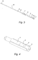
- Fig. 3 shows more clearly the plasma-generating system.
- the system comprises a cathode 8, which is mounted in a cathode holder 9, which in turn is connected to an electrical conductor 11 for connection to a source of electric energy.
- the conductor 11 is enclosed by an insulator 10.
- the cathode holder 9 is designed to be fitted in a certain position in a holder element 7, which is formed of an insulating material, such as a temperature resistant plastic material.
- a cylindrical insulating tube 6 is provided in the holder element 7, between the cathode 8 and the inside of the holder element 7.
- the insulating tube 6 is made of a heat-insulating ceramic material.
- electrodes 5, 3, separated by insulators 4, are arranged in the holding means in such manner that they form a channel for heating the plasma.
- two electrodes 5, 3 are provided, which are separated by one insulator.
- the shape of the electrodes as well as the channel diameter can be adapted to any desired purpose.
- the first electrode 5, the insulator 4 and the second electrode 3 are press fitted together.
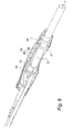
- the electrodes 5, 3 and the insulator 4 are here press fitted to the holder element 7. In Fig. 4 , the electrodes 5, 3 and the insulator 4 are shown when mounted in the holder element 7.
- the holder element 7 is here conveniently designed according to the purpose, with a cylindrical part for connection to the cathode holder 9, and outwardly extending arms between which the electrodes 5, 3 and the insulator 4 can be press fitted.
- the connection to the cathode holder 9 is such that the cathode 8 is arranged concentrically with and spaced from the electrode 5 closest to the cathode 8.
- the electrode 3 furthest away from the cathode 8 is in contact with an annular gasket 2, which in turn bears against the anode 1.
- the holder element 7, with the cathode holder 9, is mounted in the plasma-generating portion of the tubular housing 12.
- the conductor 11 connected at the cathode, and the insulation 10 associated therewith, extends through the gas supply channel 17 in the supply portion of the housing.
- the anode 1 is connected to the housing 12 and the plasma-generating system has such dimensions relative to the housing 12 that a predetermined compressive force is exerted on the gasket 2 between the anode 1 and the electrode 3 closest thereto. This ensures that a watertight seal is obtained between the anode and the housing 12.
- the controlling compressive force can be achieved by means of threading between the anode 1 and the housing 12, welding or soldering. In any case, the interconnection of the anode 1 and the housing 12 is such as to provide an electrical contact between the two.
- the cylindrical portion of the holder element 7 that encloses the cathode 8 is designed to fit in the gas supply channel 17.
- the size of the electrodes and the shape of the arms of the holder element are such as not to prevent the coolant from flowing out and in through the cooling channels 15, 16 and on between the electrodes 5, 3 and the inner wall of the housing 12.
- the coolant is preferably water, although other fluids are conceivable.
- a coupling device is provided (detached in Fig. 1 ).
- the coupling device comprises two parts, an outlet end 13, which defines coupling channels to be fitted in the channels 15, 16, 17 of the tubular housing 12, and an inlet end 14 provided with hose couplings 18, 19, 20 for coupling hoses to each of said coupling channels.
- the hose couplings 18, 19, 20 can, for example, be "olive couplings”.
- the coupling device is provided with a conductor opening through which the conductor 11 extends for connection to an energy source.
- hose couplings 18, 19, 20 flexible hoses conveniently extend to a coupling terminal for connection to a supply unit.
- Fig. 7 illustrates one example of such a coupling terminal.
- Fig. 8 shows the device in Fig. 1 when assembled with a handle portion.
- the handle portion partially encloses the housing 12 and extends over the coupling device and over a portion of the supply hoses.
- the housing 12 is here provided with a first contact ring 27, which is connected to earth. This is to ensure that the device has zero potential.
- the housing is provided with a second contact ring 24, which is usable to control the earthing of the housing 12.
- the handle portion further comprises a printed circuit card 25, which contains, inter alia, an indication component, whose electrical resistance can be read and used to indicate what type of device is being used.
- the handle portion is also provided with buttons 26 to switch the device on and off.
- Fig. 9 shows the device in Fig. 8 with the whole handle portion.
- the handle has an ergonomic design that allows it to be held and operated comfortably.
- Fig. 10 illustrates a second embodiment of the invention.
- the tubular housing 12 is here longer than in the embodiment described previously, and the shape of the handle is slightly different. This embodiment is particularly suitable for laparoscopic surgery.
- the handle portion does not have any buttons and instead the device is switched on and off by means of a footswitch.
- the device can be provided as a disposable instrument.
- the whole device including housing, coupling device, hoses and coupling terminal, can be sold as a disposable instrument.
- the housing and its content may be disposable, and adapted to be connected to non-disposable handles and hoses, etc.
- the plasma-generating gas is the same type of gases that are used in prior-art instruments, for example argon.
- the number and design of the electrodes may be varied depending on the type of plasma-generating gas used and the desired properties of the plasma.
- the length of the housing, and of its supply portion and plasma-generating portion, respectively may be varied to fit different applications.
- the coupling device may be designed in several ways just like the handle.
- the number of additional channels and their cross section may be varied. For example, three additional channels may be provided, two being used for supplying and discharging a coolant and one being used for sucking liquid from an area of surgery.
- the housing and the anode may be made in one piece rather than as two units put together according to the embodiment described above.
Landscapes
- Health & Medical Sciences (AREA)
- Surgery (AREA)
- Engineering & Computer Science (AREA)
- Life Sciences & Earth Sciences (AREA)
- Biomedical Technology (AREA)
- Molecular Biology (AREA)
- Nuclear Medicine, Radiotherapy & Molecular Imaging (AREA)
- Plasma & Fusion (AREA)
- Physics & Mathematics (AREA)
- Heart & Thoracic Surgery (AREA)
- Medical Informatics (AREA)
- Otolaryngology (AREA)
- Animal Behavior & Ethology (AREA)
- General Health & Medical Sciences (AREA)
- Public Health (AREA)
- Veterinary Medicine (AREA)
- Surgical Instruments (AREA)
- Plasma Technology (AREA)
Claims (28)
- Dispositif chirurgical au plasma destiné à réduire les saignements dans les tissus vivants au moyen d'un plasma gazeux, comprenant un système générant du plasma présentant une anode (1), une cathode (8) et un canal d'amenée de gaz (17) pour fournir du gaz au système générant du plasma, le système générant du plasma comprenant au moins une électrode (3, 5) qui est agencée entre ladite cathode (8) et ladite anode (1), et le système générant du plasma étant entouré par un logement (12) en matériau à conductivité électrique qui est relié à l'anode (1), dans lequel ledit logement (12) forme ledit canal d'amenée de gaz (17).
- Dispositif chirurgical au plasma selon la revendication 1, dans lequel ledit logement (12), en plus dudit canal d'amenée de gaz (17), forme au moins un canal supplémentaire (15, 16).
- Dispositif chirurgical au plasma selon la revendication 2, dans lequel ledit logement (12), en plus dudit canal d'amenée de gaz (17), forme au moins deux canaux supplémentaires (15, 16).
- Dispositif chirurgical au plasma selon la revendication 3, dans lequel ledit canal d'amenée de gaz (17) est agencé au centre du logement (12) et les canaux supplémentaires (15, 16) sont agencés le long de la circonférence du canal d'amenée de gaz (17).
- Dispositif chirurgical au plasma selon la revendication 3 ou 4, dans lequel lesdits canaux supplémentaires (15, 16) sont des canaux de refroidissement pour fournir et évacuer un réfrigérant.
- Dispositif chirurgical au plasma selon l'une quelconque des revendications précédentes, dans lequel le logement (12) forme une partie d'amenée dans laquelle ledit canal d'amenée de gaz (17) est formé, et une partie générant du plasma, dans laquelle le système générant du plasma est prévu.
- Dispositif chirurgical au plasma selon l'une quelconque des revendications précédentes, dans lequel ladite cathode (8) est reliée à un conducteur (11) pour la connexion à une source de tension.
- Dispositif chirurgical au plasma selon la revendication 7, dans lequel ledit conducteur (11) est adapté pour s'étendre à travers l'un des canaux (15, 16, 17) dans ledit logement (12).
- Dispositif chirurgical au plasma selon la revendication 8, dans lequel ledit conducteur (11) s'étend à travers un canal d'amenée de gaz (17) agencé au centre dudit logement (12).
- Dispositif chirurgical au plasma selon l'une quelconque des revendications précédentes, dans lequel ledit le système générant du plasma comprend au moins deux électrodes (3, 5) qui sont isolées l'une de l'autre par un isolateur (4).
- Dispositif chirurgical au plasma selon l'une quelconque des revendications précédentes, dans lequel ladite au moins une électrode (3, 5) est montée dans un moyen de retenue (7) fabriqué dans un matériau à conductivité électrique.
- Dispositif chirurgical au plasma selon la revendication 11, dans lequel ladite au moins une électrode (3, 5) et un isolateur (4) si présent, sont ajustés par pression sur ledit moyen de retenue (7).
- Dispositif chirurgical au plasma selon la revendication 11 ou 12, dans lequel ladite cathode (8) est agencée dans le moyen de retenue (7) de manière concentrique avec, et espacée, d'une électrode (5) la plus proche de la cathode (8).
- Dispositif chirurgical au plasma selon la revendication 13, dans lequel ladite cathode (8) est montée dans le moyen de retenue (7) au moyen d'un porte-cathode (9) qui est ajusté par pression dans le moyen de retenue (7).
- Dispositif chirurgical au plasma selon la revendication 13 ou 14, dans lequel un tube isolant (6) en matériau céramique est monté à l'intérieur du moyen de retenue (7) de façon à entourer la cathode (8).
- Dispositif chirurgical au plasma selon l'une quelconque des revendications 13 à 15, dans lequel le moyen de retenue (7) présente une extrémité de connexion qui est connectée audit canal d'amenée de gaz (17), de façon à ce que le gaz passe à travers le moyen de retenue (7) jusqu'à la cathode (8) puis à travers ladite au moins une électrode (3, 5) en direction de l'anode (1).
- Dispositif chirurgical au plasma selon la revendication 16, dans lequel le moyen de retenue (7) présente une forme extérieure de manière à pouvoir permettre à un fluide de s'écouler respectivement depuis et vers les canaux supplémentaires (15, 16) dans un espace formé entre le moyen de retenue (7) avec ladite électrode (3, 5), et des isolateurs (4) si présents, et la paroi intérieure du logement (12) sur le moyen de retenue (7).
- Dispositif chirurgical au plasma selon l'une quelconque des revendications précédentes, dans lequel un joint statique (2) est agencé entre l'anode (1) et l'électrode (3) la plus proche de l'anode (1), et le système générant du plasma est agencé de telle manière dans le logement (12) qu'une force de compression prédéterminée est appliquée sur le joint statique (2) de façon à ce qu'un joint étanche à l'eau soit établi entre le logement (12) et l'anode (1) et que le contact électrique entre eux soit assuré.
- Dispositif chirurgical au plasma selon l'une quelconque des revendications précédentes, dans lequel ledit logement (12) est entouré par une première bague de contact (27) en contact électrique avec celui-ci, laquelle bague de contact est reliée à la terre.
- Dispositif chirurgical au plasma selon la revendication 19, dans lequel ledit logement (12) est entouré par une deuxième bague de contact (24) qui est capable d'être utilisée pour contrôler en permanence que le logement (12) est relié à la terre.
- Dispositif chirurgical au plasma selon l'une quelconque des revendications 2 à 19, dans lequel un dispositif de liaison est prévu pour relier l'amenée de gaz audit canal d'amenée de gaz (17) et toute fonction souhaitée auxdits canaux supplémentaires (15, 16).
- Dispositif chirurgical au plasma selon la revendication 21, dans lequel ledit dispositif de liaison présente une extrémité de sortie qui définit des canaux de liaison pour obtenir une insertion étanche aux fluides dans ledit canal d'amenée de gaz (17) et lesdits canaux supplémentaires (15, 16), et une extrémité d'admission munie de raccordements de tubes (18, 19, 20) pour raccorder des tubes à chacun desdits canaux de liaison.
- Dispositif chirurgical au plasma selon la revendication 21 ou 22, dans lequel ledit dispositif de liaison comprend également une ouverture de conducteur à travers laquelle un conducteur de cathode (11) s'étend pour la connexion à une source de tension.
- Dispositif chirurgical au plasma selon l'une quelconque des revendications 2 à 23, dans lequel ledit logement (12) est relié aux tubes pour fournir du gaz et toute fonction souhaitée des canaux supplémentaires, lesquels tubes sont reliés, par leur autre extrémité, à un connecteur pour la connexion à une unité d'amenée.
- Dispositif chirurgical au plasma selon l'une quelconque des revendications précédentes qui comprend une partie de poignée qui entoure au moins partiellement ledit logement (12) pour permettre une manipulation aisée du dispositif.
- Dispositif chirurgical au plasma selon la revendication 20 qui comprend un circuit adapté pour distinguer le type de dispositif au moyen de la résistance d'un composant indicateur (25).
- Dispositif chirurgical au plasma selon l'une quelconque des revendications précédentes qui comprend une première touche (26) pour allumer et éteindre le système générant du plasma.
- Dispositif chirurgical au plasma selon la revendication 27, qui, pour une fiabilité accrue, présente une seconde touche (26).
Applications Claiming Priority (3)
| Application Number | Priority Date | Filing Date | Title |
|---|---|---|---|
| SE0202958A SE524441C2 (sv) | 2002-10-04 | 2002-10-04 | Plasmakirurgisk anordning för reducering av blödning i levande vävnad med hjälp av ett gasplasma |
| SE0202958 | 2002-10-04 | ||
| PCT/SE2003/001537 WO2004030551A1 (fr) | 2002-10-04 | 2003-10-02 | Dispositif chirurgical au plasma |
Publications (2)
| Publication Number | Publication Date |
|---|---|
| EP1545358A1 EP1545358A1 (fr) | 2005-06-29 |
| EP1545358B1 true EP1545358B1 (fr) | 2011-11-23 |
Family
ID=20289195
Family Applications (1)
| Application Number | Title | Priority Date | Filing Date |
|---|---|---|---|
| EP03748836A Expired - Lifetime EP1545358B1 (fr) | 2002-10-04 | 2003-10-02 | Dispositif chirurgical au plasma |
Country Status (11)
| Country | Link |
|---|---|
| US (1) | US7361175B2 (fr) |
| EP (1) | EP1545358B1 (fr) |
| JP (1) | JP2006501016A (fr) |
| CN (1) | CN100408000C (fr) |
| AT (1) | ATE534340T1 (fr) |
| AU (1) | AU2003268801A1 (fr) |
| CA (1) | CA2499135C (fr) |
| DK (1) | DK1545358T3 (fr) |
| ES (1) | ES2373648T3 (fr) |
| SE (1) | SE524441C2 (fr) |
| WO (1) | WO2004030551A1 (fr) |
Families Citing this family (72)
| Publication number | Priority date | Publication date | Assignee | Title |
|---|---|---|---|---|
| US8048070B2 (en) | 2000-03-06 | 2011-11-01 | Salient Surgical Technologies, Inc. | Fluid-assisted medical devices, systems and methods |
| US7811282B2 (en) | 2000-03-06 | 2010-10-12 | Salient Surgical Technologies, Inc. | Fluid-assisted electrosurgical devices, electrosurgical unit with pump and methods of use thereof |
| US6953461B2 (en) | 2002-05-16 | 2005-10-11 | Tissuelink Medical, Inc. | Fluid-assisted medical devices, systems and methods |
| US6689131B2 (en) | 2001-03-08 | 2004-02-10 | Tissuelink Medical, Inc. | Electrosurgical device having a tissue reduction sensor |
| US6558385B1 (en) | 2000-09-22 | 2003-05-06 | Tissuelink Medical, Inc. | Fluid-assisted medical device |
| JP2004500207A (ja) | 2000-03-06 | 2004-01-08 | ティシューリンク・メディカル・インコーポレーテッド | 流体配給システム及び電気外科用器具コントローラ |
| EP2275050A1 (fr) | 2001-09-05 | 2011-01-19 | Salient Surgical Technologies, Inc. | Dispositifs, procédés et systèmes chirurgicaux assistés par un fluide |
| AU2002357166A1 (en) | 2001-12-12 | 2003-06-23 | Tissuelink Medical, Inc. | Fluid-assisted medical devices, systems and methods |
| JP2006504472A (ja) | 2002-10-29 | 2006-02-09 | ティシューリンク・メディカル・インコーポレーテッド | 流体補助電気外科手術鋏及び方法 |
| US7727232B1 (en) | 2004-02-04 | 2010-06-01 | Salient Surgical Technologies, Inc. | Fluid-assisted medical devices and methods |
| DE102005021304A1 (de) * | 2005-05-09 | 2006-11-23 | Erbe Elektromedizin Gmbh | Endoskopische Chirurgieeinrichtung für eine Argon-Plasma-Koagulation (APC) |
| SE529058C2 (sv) | 2005-07-08 | 2007-04-17 | Plasma Surgical Invest Ltd | Plasmaalstrande anordning, plasmakirurgisk anordning, användning av en plasmakirurgisk anordning och förfarande för att bilda ett plasma |
| SE529056C2 (sv) | 2005-07-08 | 2007-04-17 | Plasma Surgical Invest Ltd | Plasmaalstrande anordning, plasmakirurgisk anordning och användning av en plasmakirurgisk anordning |
| SE529053C2 (sv) | 2005-07-08 | 2007-04-17 | Plasma Surgical Invest Ltd | Plasmaalstrande anordning, plasmakirurgisk anordning och användning av en plasmakirurgisk anordning |
| US7648503B2 (en) * | 2006-03-08 | 2010-01-19 | Covidien Ag | Tissue coagulation method and device using inert gas |
| US7928338B2 (en) * | 2007-02-02 | 2011-04-19 | Plasma Surgical Investments Ltd. | Plasma spraying device and method |
| US7589473B2 (en) * | 2007-08-06 | 2009-09-15 | Plasma Surgical Investments, Ltd. | Pulsed plasma device and method for generating pulsed plasma |
| US8735766B2 (en) * | 2007-08-06 | 2014-05-27 | Plasma Surgical Investments Limited | Cathode assembly and method for pulsed plasma generation |
| US8882756B2 (en) | 2007-12-28 | 2014-11-11 | Medtronic Advanced Energy Llc | Fluid-assisted electrosurgical devices, methods and systems |
| JP2011521735A (ja) | 2008-05-30 | 2011-07-28 | コロラド ステート ユニバーシティ リサーチ ファンデーション | プラズマを発生させるためのシステム、方法、および装置 |
| WO2009146432A1 (fr) | 2008-05-30 | 2009-12-03 | Colorado State University Research Foundation | Dispositif de source chimique à base de plasma et procédé d'utilisation de celle-ci |
| US8994270B2 (en) | 2008-05-30 | 2015-03-31 | Colorado State University Research Foundation | System and methods for plasma application |
| US20100022824A1 (en) | 2008-07-22 | 2010-01-28 | Cybulski James S | Tissue modification devices and methods of using the same |
| US20150157387A1 (en) * | 2008-11-12 | 2015-06-11 | Trice Medical, Inc. | Tissue visualization and modification devices and methods |
| US20110009694A1 (en) * | 2009-07-10 | 2011-01-13 | Schultz Eric E | Hand-held minimally dimensioned diagnostic device having integrated distal end visualization |
| US20110276113A1 (en) * | 2010-04-12 | 2011-11-10 | Cybulski James S | RF Tissue Modulation Devices and Methods of Using the Same |
| US20100121139A1 (en) | 2008-11-12 | 2010-05-13 | Ouyang Xiaolong | Minimally Invasive Imaging Systems |
| US9254168B2 (en) | 2009-02-02 | 2016-02-09 | Medtronic Advanced Energy Llc | Electro-thermotherapy of tissue using penetrating microelectrode array |
| WO2010096809A1 (fr) | 2009-02-23 | 2010-08-26 | Salient Surgical Technologies, Inc. | Dispositif électrochirurgical assisté par un fluide et procédés pour l'utiliser |
| IN2012DN01917A (fr) | 2009-09-08 | 2015-07-24 | Salient Surgical Tech Inc | |
| US8222822B2 (en) | 2009-10-27 | 2012-07-17 | Tyco Healthcare Group Lp | Inductively-coupled plasma device |
| US8613742B2 (en) * | 2010-01-29 | 2013-12-24 | Plasma Surgical Investments Limited | Methods of sealing vessels using plasma |
| EP2544616B1 (fr) | 2010-03-11 | 2017-09-06 | Medtronic Advanced Energy LLC | Instrument tranchant électrochirurgical bipolaire comprenant un contact d'électrode de référence indépendante de la position |
| EP2552340A4 (fr) | 2010-03-31 | 2015-10-14 | Univ Colorado State Res Found | Dispositif à plasma à interface liquide-gaz |
| JP2013529352A (ja) | 2010-03-31 | 2013-07-18 | コロラド ステート ユニバーシティー リサーチ ファウンデーション | 液体−気体界面プラズマデバイス |
| US20110295249A1 (en) * | 2010-05-28 | 2011-12-01 | Salient Surgical Technologies, Inc. | Fluid-Assisted Electrosurgical Devices, and Methods of Manufacture Thereof |
| US9138289B2 (en) | 2010-06-28 | 2015-09-22 | Medtronic Advanced Energy Llc | Electrode sheath for electrosurgical device |
| US8906012B2 (en) | 2010-06-30 | 2014-12-09 | Medtronic Advanced Energy Llc | Electrosurgical devices with wire electrode |
| US8920417B2 (en) | 2010-06-30 | 2014-12-30 | Medtronic Advanced Energy Llc | Electrosurgical devices and methods of use thereof |
| US9089319B2 (en) | 2010-07-22 | 2015-07-28 | Plasma Surgical Investments Limited | Volumetrically oscillating plasma flows |
| US8668687B2 (en) | 2010-07-29 | 2014-03-11 | Covidien Lp | System and method for removing medical implants |
| US9023040B2 (en) | 2010-10-26 | 2015-05-05 | Medtronic Advanced Energy Llc | Electrosurgical cutting devices |
| KR101248105B1 (ko) | 2011-01-07 | 2013-03-27 | 서울대학교산학협력단 | 탈출 수핵 분해를 위한 최소침습성 플라즈마 생성전극 구조 |
| US9427281B2 (en) | 2011-03-11 | 2016-08-30 | Medtronic Advanced Energy Llc | Bronchoscope-compatible catheter provided with electrosurgical device |
| US9750565B2 (en) | 2011-09-30 | 2017-09-05 | Medtronic Advanced Energy Llc | Electrosurgical balloons |
| US8870864B2 (en) | 2011-10-28 | 2014-10-28 | Medtronic Advanced Energy Llc | Single instrument electrosurgery apparatus and its method of use |
| US9226792B2 (en) | 2012-06-12 | 2016-01-05 | Medtronic Advanced Energy Llc | Debridement device and method |
| US11234760B2 (en) | 2012-10-05 | 2022-02-01 | Medtronic Advanced Energy Llc | Electrosurgical device for cutting and removing tissue |
| US9269544B2 (en) | 2013-02-11 | 2016-02-23 | Colorado State University Research Foundation | System and method for treatment of biofilms |
| US9532826B2 (en) | 2013-03-06 | 2017-01-03 | Covidien Lp | System and method for sinus surgery |
| US9555145B2 (en) | 2013-03-13 | 2017-01-31 | Covidien Lp | System and method for biofilm remediation |
| US10314647B2 (en) | 2013-12-23 | 2019-06-11 | Medtronic Advanced Energy Llc | Electrosurgical cutting instrument |
| US10342579B2 (en) | 2014-01-13 | 2019-07-09 | Trice Medical, Inc. | Fully integrated, disposable tissue visualization device |
| US11547446B2 (en) | 2014-01-13 | 2023-01-10 | Trice Medical, Inc. | Fully integrated, disposable tissue visualization device |
| US9370295B2 (en) | 2014-01-13 | 2016-06-21 | Trice Medical, Inc. | Fully integrated, disposable tissue visualization device |
| US10813686B2 (en) | 2014-02-26 | 2020-10-27 | Medtronic Advanced Energy Llc | Electrosurgical cutting instrument |
| RU2017102681A (ru) | 2014-06-30 | 2018-07-30 | Ориджин, Инк. | Аппарат для применения оксида азота в месте лечения |
| US9974599B2 (en) | 2014-08-15 | 2018-05-22 | Medtronic Ps Medical, Inc. | Multipurpose electrosurgical device |
| DE102014116253A1 (de) * | 2014-11-07 | 2016-05-12 | Ovesco Endoscopy Ag | Plasmachirurgisches Gerät mit Abstandshalter |
| US10188456B2 (en) | 2015-02-18 | 2019-01-29 | Medtronic Xomed, Inc. | Electrode assembly for RF energy enabled tissue debridement device |
| US10376302B2 (en) | 2015-02-18 | 2019-08-13 | Medtronic Xomed, Inc. | Rotating electrical connector for RF energy enabled tissue debridement device |
| JP6661652B2 (ja) | 2015-02-18 | 2020-03-11 | メドトロニック・ゾーメド・インコーポレーテッド | Rfエネルギー使用可能な組織デブリドマンデバイス |
| CN108024695B (zh) | 2015-08-11 | 2021-05-04 | 特里斯医疗有限公司 | 完全集成的一次性组织可视化装置 |
| US11389227B2 (en) | 2015-08-20 | 2022-07-19 | Medtronic Advanced Energy Llc | Electrosurgical device with multivariate control |
| US11051875B2 (en) | 2015-08-24 | 2021-07-06 | Medtronic Advanced Energy Llc | Multipurpose electrosurgical device |
| US10716612B2 (en) | 2015-12-18 | 2020-07-21 | Medtronic Advanced Energy Llc | Electrosurgical device with multiple monopolar electrode assembly |
| EP3554995B1 (fr) | 2016-12-14 | 2023-07-12 | Origin, Inc. | Dispositif et méthode de production d'oxyde nitrique à haute concentration et basse température |
| CN110446530B (zh) * | 2017-03-20 | 2020-12-01 | 纳华公司 | 用于生成和递送低温等离子体的装置 |
| US12023082B2 (en) | 2017-10-06 | 2024-07-02 | Medtronic Advanced Energy Llc | Hemostatic thermal sealer |
| WO2019191705A1 (fr) | 2018-03-29 | 2019-10-03 | Trice Medical, Inc. | Endoscope entièrement intégré ayant des capacités de biopsie et procédés d'utilisation |
| EP4205515A2 (fr) * | 2020-08-28 | 2023-07-05 | Plasma Surgical Investments Limited | Systèmes, procédés et dispositifs pour générer un flux de plasma étendu principalement radialement |
| CN113520571A (zh) * | 2021-06-18 | 2021-10-22 | 西安高通医学发展有限公司 | 用于喉部扁桃体的低温等离子体多功能手术刀 |
Family Cites Families (10)
| Publication number | Priority date | Publication date | Assignee | Title |
|---|---|---|---|---|
| US3434476A (en) | 1966-04-07 | 1969-03-25 | Robert F Shaw | Plasma arc scalpel |
| BE795236A (fr) | 1972-02-09 | 1973-05-29 | Vysoka Skola Banska Ostrava | Bruleur a plasma avec alimentation axiale du gaz stabilisant |
| US3938525A (en) * | 1972-05-15 | 1976-02-17 | Hogle-Kearns International | Plasma surgery |
| US5720745A (en) * | 1992-11-24 | 1998-02-24 | Erbe Electromedizin Gmbh | Electrosurgical unit and method for achieving coagulation of biological tissue |
| US5320621A (en) * | 1993-05-05 | 1994-06-14 | Birtcher Medial Systems, Inc. | Technique for incorporating an electrode within a nozzle |
| SE503334C2 (sv) | 1993-06-01 | 1996-05-28 | Nikval Int Ab | Anordning för att stoppa en blödning och bilda en sårskorpa medelst en plasmastråle |
| EP0784452B1 (fr) * | 1994-08-29 | 2003-10-22 | Plasma Surgical Investments Limited | Dispositif pour stopper le saignement de tissus vivants chez l'homme et chez les animaux |
| US6213999B1 (en) * | 1995-03-07 | 2001-04-10 | Sherwood Services Ag | Surgical gas plasma ignition apparatus and method |
| US6479785B1 (en) * | 1998-07-09 | 2002-11-12 | Richard J. Fugo | Device for plasma incision of mater with a specifically tuned radiofrequencty electromagnetic field generator |
| US6475215B1 (en) | 2000-10-12 | 2002-11-05 | Naim Erturk Tanrisever | Quantum energy surgical device and method |
-
2002
- 2002-10-04 SE SE0202958A patent/SE524441C2/sv unknown
-
2003
- 2003-10-02 DK DK03748836.8T patent/DK1545358T3/da active
- 2003-10-02 JP JP2004541385A patent/JP2006501016A/ja active Pending
- 2003-10-02 CA CA2499135A patent/CA2499135C/fr not_active Expired - Lifetime
- 2003-10-02 ES ES03748836T patent/ES2373648T3/es not_active Expired - Lifetime
- 2003-10-02 AU AU2003268801A patent/AU2003268801A1/en not_active Abandoned
- 2003-10-02 EP EP03748836A patent/EP1545358B1/fr not_active Expired - Lifetime
- 2003-10-02 WO PCT/SE2003/001537 patent/WO2004030551A1/fr not_active Ceased
- 2003-10-02 AT AT03748836T patent/ATE534340T1/de active
- 2003-10-02 CN CNB2003801009075A patent/CN100408000C/zh not_active Expired - Lifetime
- 2003-10-02 US US10/528,061 patent/US7361175B2/en not_active Expired - Lifetime
Also Published As
| Publication number | Publication date |
|---|---|
| CA2499135A1 (fr) | 2004-04-15 |
| CN100408000C (zh) | 2008-08-06 |
| SE0202958D0 (sv) | 2002-10-04 |
| US7361175B2 (en) | 2008-04-22 |
| SE524441C2 (sv) | 2004-08-10 |
| CA2499135C (fr) | 2013-06-04 |
| EP1545358A1 (fr) | 2005-06-29 |
| AU2003268801A1 (en) | 2004-04-23 |
| DK1545358T3 (da) | 2012-01-09 |
| US20060004354A1 (en) | 2006-01-05 |
| WO2004030551A1 (fr) | 2004-04-15 |
| JP2006501016A (ja) | 2006-01-12 |
| ES2373648T3 (es) | 2012-02-07 |
| SE0202958L (sv) | 2004-04-05 |
| ATE534340T1 (de) | 2011-12-15 |
| CN1703167A (zh) | 2005-11-30 |
Similar Documents
| Publication | Publication Date | Title |
|---|---|---|
| EP1545358B1 (fr) | Dispositif chirurgical au plasma | |
| EP1041935B1 (fr) | Instrument electrochirurgical perfectionne | |
| EP2981222B1 (fr) | Système d'ablation médicale | |
| EP1905286B1 (fr) | Dispositif generateur de plasma et dispositif chirurgical au plasma | |
| EP1433427B1 (fr) | Système électro-chirurgical bipolaire, amélioré par l'utilisation d'un plasma | |
| CN102458290B (zh) | 内窥镜的外科仪器 | |
| EP0633749B1 (fr) | Outil de coupe electrochirurgical et bipolaire a main | |
| US5626560A (en) | Diathermic hand-held instrument with an endoscopic probe | |
| US7763018B2 (en) | Cool-tip thermocouple including two-piece hub | |
| CN105120782B (zh) | 具有排烟功能的氩束辅助电外科手术笔 | |
| US8114181B2 (en) | Reflux trap device | |
| CA2138076A1 (fr) | Instruments electrochirurgicaux monopolaires | |
| CN110200695A (zh) | 被配置用于与辅助设备一起使用的等离子体发生器 | |
| US10765472B2 (en) | Electrosurgical instrument extension attachment | |
| KR20220050779A (ko) | 멀티 루멘 프로브 | |
| AU2016265602B2 (en) | Device for resecting an organ in a cavity of a body | |
| US20050283147A1 (en) | Surgical treatment device and surgical treatment system | |
| CN212438819U (zh) | 等离子电极和等离子设备 | |
| CN112022327B (zh) | 等离子电极和等离子设备 | |
| US20220087731A1 (en) | Removable tip for use with electrosurgical devices | |
| HK40009158A (zh) | 在esu单极和双极模式中使用的超极性电外科刀片和超极性电外科笔以及伸缩式电外科笔 |
Legal Events
| Date | Code | Title | Description |
|---|---|---|---|
| PUAI | Public reference made under article 153(3) epc to a published international application that has entered the european phase |
Free format text: ORIGINAL CODE: 0009012 |
|
| 17P | Request for examination filed |
Effective date: 20050304 |
|
| AK | Designated contracting states |
Kind code of ref document: A1 Designated state(s): AT BE BG CH CY CZ DE DK EE ES FI FR GB GR HU IE IT LI LU MC NL PT RO SE SI SK TR |
|
| AX | Request for extension of the european patent |
Extension state: AL LT LV MK |
|
| DAX | Request for extension of the european patent (deleted) | ||
| GRAC | Information related to communication of intention to grant a patent modified |
Free format text: ORIGINAL CODE: EPIDOSCIGR1 |
|
| GRAP | Despatch of communication of intention to grant a patent |
Free format text: ORIGINAL CODE: EPIDOSNIGR1 |
|
| GRAS | Grant fee paid |
Free format text: ORIGINAL CODE: EPIDOSNIGR3 |
|
| GRAA | (expected) grant |
Free format text: ORIGINAL CODE: 0009210 |
|
| AK | Designated contracting states |
Kind code of ref document: B1 Designated state(s): AT BE BG CH CY CZ DE DK EE ES FI FR GB GR HU IE IT LI LU MC NL PT RO SE SI SK TR |
|
| REG | Reference to a national code |
Ref country code: GB Ref legal event code: FG4D |
|
| REG | Reference to a national code |
Ref country code: CH Ref legal event code: EP |
|
| REG | Reference to a national code |
Ref country code: IE Ref legal event code: FG4D |
|
| REG | Reference to a national code |
Ref country code: DK Ref legal event code: T3 |
|
| REG | Reference to a national code |
Ref country code: ES Ref legal event code: FG2A Ref document number: 2373648 Country of ref document: ES Kind code of ref document: T3 Effective date: 20120207 |
|
| REG | Reference to a national code |
Ref country code: DE Ref legal event code: R096 Ref document number: 60339212 Country of ref document: DE Effective date: 20120223 |
|
| REG | Reference to a national code |
Ref country code: NL Ref legal event code: VDEP Effective date: 20111123 |
|
| PG25 | Lapsed in a contracting state [announced via postgrant information from national office to epo] |
Ref country code: PT Free format text: LAPSE BECAUSE OF FAILURE TO SUBMIT A TRANSLATION OF THE DESCRIPTION OR TO PAY THE FEE WITHIN THE PRESCRIBED TIME-LIMIT Effective date: 20120323 Ref country code: SE Free format text: LAPSE BECAUSE OF FAILURE TO SUBMIT A TRANSLATION OF THE DESCRIPTION OR TO PAY THE FEE WITHIN THE PRESCRIBED TIME-LIMIT Effective date: 20111123 Ref country code: GR Free format text: LAPSE BECAUSE OF FAILURE TO SUBMIT A TRANSLATION OF THE DESCRIPTION OR TO PAY THE FEE WITHIN THE PRESCRIBED TIME-LIMIT Effective date: 20120224 Ref country code: BE Free format text: LAPSE BECAUSE OF FAILURE TO SUBMIT A TRANSLATION OF THE DESCRIPTION OR TO PAY THE FEE WITHIN THE PRESCRIBED TIME-LIMIT Effective date: 20111123 Ref country code: NL Free format text: LAPSE BECAUSE OF FAILURE TO SUBMIT A TRANSLATION OF THE DESCRIPTION OR TO PAY THE FEE WITHIN THE PRESCRIBED TIME-LIMIT Effective date: 20111123 Ref country code: SI Free format text: LAPSE BECAUSE OF FAILURE TO SUBMIT A TRANSLATION OF THE DESCRIPTION OR TO PAY THE FEE WITHIN THE PRESCRIBED TIME-LIMIT Effective date: 20111123 |
|
| PG25 | Lapsed in a contracting state [announced via postgrant information from national office to epo] |
Ref country code: CY Free format text: LAPSE BECAUSE OF FAILURE TO SUBMIT A TRANSLATION OF THE DESCRIPTION OR TO PAY THE FEE WITHIN THE PRESCRIBED TIME-LIMIT Effective date: 20111123 |
|
| PG25 | Lapsed in a contracting state [announced via postgrant information from national office to epo] |
Ref country code: CZ Free format text: LAPSE BECAUSE OF FAILURE TO SUBMIT A TRANSLATION OF THE DESCRIPTION OR TO PAY THE FEE WITHIN THE PRESCRIBED TIME-LIMIT Effective date: 20111123 Ref country code: EE Free format text: LAPSE BECAUSE OF FAILURE TO SUBMIT A TRANSLATION OF THE DESCRIPTION OR TO PAY THE FEE WITHIN THE PRESCRIBED TIME-LIMIT Effective date: 20111123 Ref country code: BG Free format text: LAPSE BECAUSE OF FAILURE TO SUBMIT A TRANSLATION OF THE DESCRIPTION OR TO PAY THE FEE WITHIN THE PRESCRIBED TIME-LIMIT Effective date: 20120223 Ref country code: SK Free format text: LAPSE BECAUSE OF FAILURE TO SUBMIT A TRANSLATION OF THE DESCRIPTION OR TO PAY THE FEE WITHIN THE PRESCRIBED TIME-LIMIT Effective date: 20111123 |
|
| PG25 | Lapsed in a contracting state [announced via postgrant information from national office to epo] |
Ref country code: RO Free format text: LAPSE BECAUSE OF FAILURE TO SUBMIT A TRANSLATION OF THE DESCRIPTION OR TO PAY THE FEE WITHIN THE PRESCRIBED TIME-LIMIT Effective date: 20111123 |
|
| REG | Reference to a national code |
Ref country code: AT Ref legal event code: MK05 Ref document number: 534340 Country of ref document: AT Kind code of ref document: T Effective date: 20111123 |
|
| PLBE | No opposition filed within time limit |
Free format text: ORIGINAL CODE: 0009261 |
|
| STAA | Information on the status of an ep patent application or granted ep patent |
Free format text: STATUS: NO OPPOSITION FILED WITHIN TIME LIMIT |
|
| 26N | No opposition filed |
Effective date: 20120824 |
|
| REG | Reference to a national code |
Ref country code: DE Ref legal event code: R097 Ref document number: 60339212 Country of ref document: DE Effective date: 20120824 |
|
| PG25 | Lapsed in a contracting state [announced via postgrant information from national office to epo] |
Ref country code: AT Free format text: LAPSE BECAUSE OF FAILURE TO SUBMIT A TRANSLATION OF THE DESCRIPTION OR TO PAY THE FEE WITHIN THE PRESCRIBED TIME-LIMIT Effective date: 20111123 |
|
| PG25 | Lapsed in a contracting state [announced via postgrant information from national office to epo] |
Ref country code: MC Free format text: LAPSE BECAUSE OF NON-PAYMENT OF DUE FEES Effective date: 20121031 |
|
| REG | Reference to a national code |
Ref country code: CH Ref legal event code: PL |
|
| PG25 | Lapsed in a contracting state [announced via postgrant information from national office to epo] |
Ref country code: FI Free format text: LAPSE BECAUSE OF FAILURE TO SUBMIT A TRANSLATION OF THE DESCRIPTION OR TO PAY THE FEE WITHIN THE PRESCRIBED TIME-LIMIT Effective date: 20111123 |
|
| REG | Reference to a national code |
Ref country code: IE Ref legal event code: MM4A |
|
| PG25 | Lapsed in a contracting state [announced via postgrant information from national office to epo] |
Ref country code: CH Free format text: LAPSE BECAUSE OF NON-PAYMENT OF DUE FEES Effective date: 20121031 Ref country code: IE Free format text: LAPSE BECAUSE OF NON-PAYMENT OF DUE FEES Effective date: 20121002 Ref country code: LI Free format text: LAPSE BECAUSE OF NON-PAYMENT OF DUE FEES Effective date: 20121031 |
|
| PG25 | Lapsed in a contracting state [announced via postgrant information from national office to epo] |
Ref country code: TR Free format text: LAPSE BECAUSE OF FAILURE TO SUBMIT A TRANSLATION OF THE DESCRIPTION OR TO PAY THE FEE WITHIN THE PRESCRIBED TIME-LIMIT Effective date: 20111123 |
|
| PG25 | Lapsed in a contracting state [announced via postgrant information from national office to epo] |
Ref country code: LU Free format text: LAPSE BECAUSE OF NON-PAYMENT OF DUE FEES Effective date: 20121002 |
|
| PG25 | Lapsed in a contracting state [announced via postgrant information from national office to epo] |
Ref country code: HU Free format text: LAPSE BECAUSE OF FAILURE TO SUBMIT A TRANSLATION OF THE DESCRIPTION OR TO PAY THE FEE WITHIN THE PRESCRIBED TIME-LIMIT Effective date: 20031002 |
|
| PGFP | Annual fee paid to national office [announced via postgrant information from national office to epo] |
Ref country code: ES Payment date: 20150915 Year of fee payment: 13 |
|
| PGFP | Annual fee paid to national office [announced via postgrant information from national office to epo] |
Ref country code: DK Payment date: 20151012 Year of fee payment: 13 |
|
| PGFP | Annual fee paid to national office [announced via postgrant information from national office to epo] |
Ref country code: IT Payment date: 20151026 Year of fee payment: 13 |
|
| REG | Reference to a national code |
Ref country code: FR Ref legal event code: PLFP Year of fee payment: 14 |
|
| REG | Reference to a national code |
Ref country code: DK Ref legal event code: EBP Effective date: 20161031 |
|
| REG | Reference to a national code |
Ref country code: FR Ref legal event code: PLFP Year of fee payment: 15 |
|
| PG25 | Lapsed in a contracting state [announced via postgrant information from national office to epo] |
Ref country code: IT Free format text: LAPSE BECAUSE OF NON-PAYMENT OF DUE FEES Effective date: 20161002 |
|
| PG25 | Lapsed in a contracting state [announced via postgrant information from national office to epo] |
Ref country code: DK Free format text: LAPSE BECAUSE OF NON-PAYMENT OF DUE FEES Effective date: 20161031 |
|
| PG25 | Lapsed in a contracting state [announced via postgrant information from national office to epo] |
Ref country code: ES Free format text: LAPSE BECAUSE OF NON-PAYMENT OF DUE FEES Effective date: 20161003 |
|
| REG | Reference to a national code |
Ref country code: FR Ref legal event code: PLFP Year of fee payment: 16 |
|
| REG | Reference to a national code |
Ref country code: ES Ref legal event code: FD2A Effective date: 20181126 |
|
| PGFP | Annual fee paid to national office [announced via postgrant information from national office to epo] |
Ref country code: GB Payment date: 20220901 Year of fee payment: 20 |
|
| PGFP | Annual fee paid to national office [announced via postgrant information from national office to epo] |
Ref country code: FR Payment date: 20220908 Year of fee payment: 20 |
|
| PGFP | Annual fee paid to national office [announced via postgrant information from national office to epo] |
Ref country code: DE Payment date: 20220831 Year of fee payment: 20 |
|
| P01 | Opt-out of the competence of the unified patent court (upc) registered |
Effective date: 20230525 |
|
| REG | Reference to a national code |
Ref country code: DE Ref legal event code: R071 Ref document number: 60339212 Country of ref document: DE |
|
| REG | Reference to a national code |
Ref country code: GB Ref legal event code: PE20 Expiry date: 20231001 |
|
| PG25 | Lapsed in a contracting state [announced via postgrant information from national office to epo] |
Ref country code: GB Free format text: LAPSE BECAUSE OF EXPIRATION OF PROTECTION Effective date: 20231001 |