EP1544971A1 - Busbar adapter - Google Patents
Busbar adapter Download PDFInfo
- Publication number
- EP1544971A1 EP1544971A1 EP04078359A EP04078359A EP1544971A1 EP 1544971 A1 EP1544971 A1 EP 1544971A1 EP 04078359 A EP04078359 A EP 04078359A EP 04078359 A EP04078359 A EP 04078359A EP 1544971 A1 EP1544971 A1 EP 1544971A1
- Authority
- EP
- European Patent Office
- Prior art keywords
- designed
- insulating
- bars
- shaped
- connection
- Prior art date
- Legal status (The legal status is an assumption and is not a legal conclusion. Google has not performed a legal analysis and makes no representation as to the accuracy of the status listed.)
- Granted
Links
- 238000010168 coupling process Methods 0.000 claims abstract description 26
- 238000005859 coupling reaction Methods 0.000 claims abstract description 26
- 230000008878 coupling Effects 0.000 claims abstract description 21
- 239000011810 insulating material Substances 0.000 claims abstract description 5
- 238000005304 joining Methods 0.000 claims description 6
- 230000014759 maintenance of location Effects 0.000 claims description 6
- 239000004020 conductor Substances 0.000 claims description 3
- 230000008485 antagonism Effects 0.000 claims description 2
- 238000004891 communication Methods 0.000 claims description 2
- 230000013011 mating Effects 0.000 claims 1
- 230000009471 action Effects 0.000 description 3
- 230000008901 benefit Effects 0.000 description 3
- 238000011161 development Methods 0.000 description 3
- 239000000463 material Substances 0.000 description 3
- 238000005728 strengthening Methods 0.000 description 3
- 210000000080 chela (arthropods) Anatomy 0.000 description 2
- 238000009826 distribution Methods 0.000 description 2
- 238000009877 rendering Methods 0.000 description 2
- 238000007493 shaping process Methods 0.000 description 2
- 229920001169 thermoplastic Polymers 0.000 description 2
- 229920001187 thermosetting polymer Polymers 0.000 description 2
- 239000004416 thermosoftening plastic Substances 0.000 description 2
- 241000761557 Lamina Species 0.000 description 1
- 230000002860 competitive effect Effects 0.000 description 1
- 230000000694 effects Effects 0.000 description 1
- 239000012777 electrically insulating material Substances 0.000 description 1
- 238000003780 insertion Methods 0.000 description 1
- 230000037431 insertion Effects 0.000 description 1
- 238000012423 maintenance Methods 0.000 description 1
- 238000004519 manufacturing process Methods 0.000 description 1
- 238000012986 modification Methods 0.000 description 1
- 230000004048 modification Effects 0.000 description 1
Images


Classifications
-
- H—ELECTRICITY
- H02—GENERATION; CONVERSION OR DISTRIBUTION OF ELECTRIC POWER
- H02B—BOARDS, SUBSTATIONS OR SWITCHING ARRANGEMENTS FOR THE SUPPLY OR DISTRIBUTION OF ELECTRIC POWER
- H02B1/00—Frameworks, boards, panels, desks, casings; Details of substations or switching arrangements
- H02B1/20—Bus-bar or other wiring layouts, e.g. in cubicles, in switchyards
- H02B1/21—Bus-bar arrangements for rack-mounted devices with withdrawable units
Definitions
- the present invention relates to a device for connection of a plurality of busbars to at least one apparatus of an electrical switchboard.
- the above switchboards in their essential parts, are constituted by: a cabinet of a normally cubic shape, which is provided with a frame having the function of structural support for the various components; a system of busbars arranged usually parallel to one another and connected each to a corresponding polarity of the supply-source network; and one or more pieces of electrical equipment, principally switches, connected, on the one hand, to the loads to which the electric power is to be distributed and, on the other, to the bars according to a wide range of configurations; there are then other components, such as panels, guides or supporting plates etc., which complete the switchboard.
- connection between bars and equipment are particularly important both as regards the economic aspect, by virtue of the number of components to be used and the corresponding times for assembly, and above all as far as the functional aspect is concerned.
- said connections in addition to providing proper mechanical coupling between the parts, must above all guarantee optimal electrical connection between the components in such a way that the electrical functionality during service will be free from faults.
- the foregoing must be obtained so as to meet certain given degrees of protection and safety according to what is set down by national and international standards currently in force.
- connection between busbars and equipment is generally obtained using a large number of elements which are used in a functionally separate way from one another. Some of them are in fact specifically dedicated to just electrical conduction, others to mechanical connection, others still just to protection and safety.
- a typical solution envisages the use for the electrical part of purposely designed conductors constituted by rigid elements, such as flat bars, or else by flexible elements, such as laminas, or by a mixed use of the two types.
- said conductive elements are then mechanically fixed to the bars and to the equipment by means of further adapting components, e.g., junctions, adaptors etc., and finally fixed together and to the components, usually by means of screws.
- a primary task of the present invention is to provide a connection device which will be able to overcome the drawbacks of the known art, and in particular which, as compared to known solutions, will enable provision of an operative connection between bars and apparatus that is simplified and improved both from the mechanical standpoint and from the electrical standpoint.
- a purpose of the present invention is to provide a device for the connection of a plurality of busbars to at least one apparatus that will enable a substantially direct electromechanical coupling between the bars and the apparatus.
- a further purpose of the present invention is to provide a device for the connection of a plurality of busbars to at least one apparatus, the structure of which may be obtained with an optimized number of parts that can be coupled together in a simplified and functionally interdependent way as compared to solutions of a known type.
- Another purpose of the present invention is to provide a connection device for busbars in a cabinet for an electrical switchboard that is suited to a simplified assembly and will enable optimized exploitation of the space available.
- Not the least important purpose of the present invention is to provide a connection device for busbars in a cabinet for an electrical switchboard that will present high reliability, and will be relatively easy to manufacture at competitive costs.
- a device for the connection of a plurality of busbars to at least one apparatus of an electrical switchboard characterized in that it comprises:
- the device according to the invention is obtained by means of a kit of components that are functionally intercorrelated which, once assembled, constitute a single functional block that is able to provide direct electrical and mechanical couplings, thus rendering superfluous the use of additional components.
- the device according to the invention designated as a whole in Figure 5 by the reference number 1, comprises means of mechanical coupling with a plurality of bars, designated in Figures 4 and 5 by the reference number 2, and connection means which are operatively coupled to the coupling means so as to enable direct electrical connection between the bars 2 and at least one apparatus of an electrical switchboard; said apparatus is, for example, typically constituted by a power switch, designated in Figure 5 by the reference number 3.
- the mechanical-coupling means comprise at least one first element 4 made of electrically insulating material, for example thermoplastic or thermosetting material.
- Said element 4 has a shaped body, for example substantially parallelepipedal, having a bottom face 5, a top face 6, a front face 7, a rear face 8, and two side faces 9.
- housing seats 10 designed to couple each with a corresponding bar 2, thus keeping the bars isolated from one another.
- said housing seats 10 are arranged on the front face 7 along the line joining the bottom face 5 and the top face 6, at a predefined distance, e.g., at a constant pitch, and substantially parallel to one another.
- ribbings 26 for structural strengthening (see in the figures BN) .
- the first insulating element 4 is provided with a plurality of longitudinal grooves 11, defined on the rear face 8 along the line joining the two side faces 9.
- said grooves 11 are arranged parallel and separate from one another, with one end open in an area corresponding to the edge of one of the two side walls 9, and are in number equal to the housing seats 10, in the case in point four.
- first element 4 there is moreover defined a plurality of through openings 12, for example of a rectangular shape, as illustrated in Figure 1, once again equal in number to the seats 10 and grooves 11.
- Each of said through openings 12 is set along the development of a corresponding housing seat 10 and sets said seat 10 in communication with a corresponding longitudinal groove 11. Furthermore, the openings 12 are arranged along the respective seats 10 at different distances from the bottom wall 7 or the top wall 8.
- first through hole 13 set along the line joining the front face 7 and the rear face 9 and having edges projecting from both of the faces 7 and 9, which define a housing seat for the purposes and functions that will emerge more clearly from the ensuing description.
- the mechanical-coupling means comprise retention and protection means operatively coupled to the first element 4 so as to favour its coupling and its withholding in a protected position with the connection means and with the bars 2.
- Said retention and protection means comprise a second element 14, which is also made of insulating material, for example thermoplastic or thermosetting material, designed to be coupled to the first insulating element 4 on the rear face 8.
- Said second element 14 has, viewed laterally, a substantially U-shaped configuration with the two side branches having the free edges shaped so as to present surfaces 15 for clamping with surfaces 16 accordingly mated defined along two opposite edges of the rear face 8.
- the central branch is provided with at least one through hole 17, which is to be aligned with a through hole 13.
- On the central branch of the element 14 there may moreover be provided strengthening ribbings 27.
- the retention and protection means further comprise: at least one elastic means 18, for example a spring, designed to be inserted into the seat defined by the rear edges of the through hole 13; at least one screw-shaped insulating element 19, designed to be inserted into the two aligned through holes 13 and 17; and at least one insulating body with a substantially planar development 20, which is to be fixed to the free end of the screw element 19 and is preferably provided with strengthening ribbings 28 on the front face.
- at least one elastic means 18, for example a spring designed to be inserted into the seat defined by the rear edges of the through hole 13
- at least one screw-shaped insulating element 19 designed to be inserted into the two aligned through holes 13 and 17
- at least one insulating body with a substantially planar development 20 which is to be fixed to the free end of the screw element 19 and is preferably provided with strengthening ribbings 28 on the front face.
- the connection means comprise a shaped element 21 made of electrically conductive material and having at least one first end surface for direct electrical connection to the apparatus 3, one second surface for mechanical coupling with the first insulating element 11, and one third surface, which can be coupled directly both electrically and mechanically to a corresponding bar.
- the conductive element 21 has: a first preferably substantially L-shaped portion, of which a first branch 22 has a free end, designed to be inserted directly in a coupling seat of the electrical apparatus 3, whilst the second branch 23 is designed to be positioned within a corresponding longitudinal groove 11 of the first insulating element.
- the shaped conductive element 21 has a second substantially pincer-shaped conductive element 24, which extends transversely from the second branch 23 of the L-shaped portion.
- Said pincer-shaped portion 24 is designed to be inserted in one of the through openings 12 and to grip a corresponding bar 2, as illustrated in Figure 4.
- the pincer-shaped portion 24 is preferably provided, in a median area from which there branch off the two pincers, with a longitudinal notch, designed to provide it with characteristics of elastic deformability so as to facilitate gripping with the bars 2.
- an elastic element 25 mounted on the pincer-shaped portion 24 so as to favour its clamping by pressure on the bar 2.
- the insulating element 4 is directly connected to the bars, by insertion of each bar 2 in a corresponding coupling seat 10.
- a conductive element 21 is coupled to the insulating element 4, with the branch 23 of the L-shaped portion inserted in a longitudinal groove 11, and the pincer-shaped body 24 that is inserted in a through opening 12 and thus grips the corresponding bar 2, so clamping it.
- conductive elements 21 are used in a number equal to that of the bars.
- Each element 21 is inserted, with its own branch 23, into a groove 11 and with the pincer 24 which is then inserted into the corresponding opening 12, so gripping the respective bar 2.
- Said elements 21 differ from one another simply in the different length of the branch 23 according to the groove 11 in which they are inserted.
- the branches 23 extend externally from the grooves 11 in such a way that the free edges of the branches 22 are inserted directly into the corresponding terminals for connection of the switch 3, as illustrated in Figure 5.
- the element 14 is coupled to the element 4, so clamping together the respective surfaces 15 and 16.
- the element 14 covers the rear part of the element 4, closing the longitudinal grooves 11 at the top and insulating the rear parts of the elements 21, with the two through holes 17 that are aligned to the two corresponding through holes 13.
- Each screw body 19 is inserted into the two aligned holes 13-17, then coming out from the front face 7. At the free end of each element 19 there is then fixed the respective insulating plane body 20.
- gripping the element 19 there is in practice obtained gripping of the latter on the second element 14 by countering the action of the spring 18 previously inserted into the seat defined by the projecting edges of the hole 13.
- gripping thanks to the combined action of the spring 18 and of the screw body 19 that work in mutual antagonism, there is a pulling effect, which, on the one hand, presses the element 14 in the direction of the element 4, and on the other pulls the body 20 so that it rests in the direction of a pair of adjacent bars.
- the device according to the invention thanks to the innovative structure and functionality of its parts, fully accomplishes the pre-set task by providing a series of advantages as compared to the known art.
- the device 1 is obtained by means of a kit of components which, when assembled, constitute as a whole a single functional block such as to provide simultaneously direct electrical and mechanical coupling between the parts, according to a solution that is simple from the constructional standpoint, is functionally effective, and facilitates considerably assembly as compared to the solutions of the known art.
- connection to the equipment typically the switches, thanks to fact that the part that conducts the current from the bars, typically the element 21, is inserted directly into the respective terminal of the switch in such a way that for final connection, nothing else remains for the operator to do but to screw the corresponding terminal, without having to use any additional components.
- connection to the bars is obtained in a direct and secure way via direct clamping of the pincer-shaped body 24 and without any intermediate components or additional operations of assembly.
- the device 1 can integrate, in its structure, elements that are able to provide functions of protection, both in the rear part of the area of coupling with the bars and in the front part, in which an anti-tampering key system is obtained, thus rendering the interventions of maintenance safer.
- the configuration that is obtained is extremely compact, enabling optimal exploitation of the spaces available so as to make available space for other components or reduce the overall dimensions of the cabinet of the switchboard.
- an electrical switchboard as is usually the case, comprises a number of apparatuses, for example different types of switches, each of which is to be connected to the bars.
- a number of devices 1 positioned along the development of the bars and mounted according to what has been described previously so as to connect the bars to each single apparatus.
- a further subject of the present invention is therefore represented by a low-voltage electrical switchboard, characterized in that it comprises one or more connection devices 1 of the type described previously.
- the device thus devised may undergo numerous modifications and variations, all falling within the scope of the inventive idea; moreover, all the items may be replaced by other technically equivalent elements.
- the shaping and/or positioning and/or number of the various seats or grooves or holes or other parts, as likewise the shaping, for example, of the elements 4 or 14, could be varied provided that they are compatible with the functions for which they are conceived.
- the materials, as well as the dimensions, may be any whatsoever according to the requirements and the state of the art.
Landscapes
- Engineering & Computer Science (AREA)
- Power Engineering (AREA)
- Patch Boards (AREA)
Abstract
Description
- The present invention relates to a device for connection of a plurality of busbars to at least one apparatus of an electrical switchboard.
- It is known that in low-voltage electrical systems, i.e., ones with operating voltages of up to 1 kV, for distribution of electric power to a number of connected loads, for example, control-instrumentation machinery, circuit branches, loads of various nature, etc., purposely designed electrical distribution switchboards are used.
- The above switchboards, in their essential parts, are constituted by: a cabinet of a normally cubic shape, which is provided with a frame having the function of structural support for the various components; a system of busbars arranged usually parallel to one another and connected each to a corresponding polarity of the supply-source network; and one or more pieces of electrical equipment, principally switches, connected, on the one hand, to the loads to which the electric power is to be distributed and, on the other, to the bars according to a wide range of configurations; there are then other components, such as panels, guides or supporting plates etc., which complete the switchboard.
- The modalities with which the connections between bars and equipment are made are particularly important both as regards the economic aspect, by virtue of the number of components to be used and the corresponding times for assembly, and above all as far as the functional aspect is concerned. In fact, said connections, in addition to providing proper mechanical coupling between the parts, must above all guarantee optimal electrical connection between the components in such a way that the electrical functionality during service will be free from faults. The foregoing must be obtained so as to meet certain given degrees of protection and safety according to what is set down by national and international standards currently in force.
- Currently, the modalities with which the bars are connected to the electrical equipment, albeit achieving the required functions, are not altogether satisfactory above all as regards the number of components used, the times and difficulties of assembly.
- In particular, the connection between busbars and equipment is generally obtained using a large number of elements which are used in a functionally separate way from one another. Some of them are in fact specifically dedicated to just electrical conduction, others to mechanical connection, others still just to protection and safety.
- For example, a typical solution envisages the use for the electrical part of purposely designed conductors constituted by rigid elements, such as flat bars, or else by flexible elements, such as laminas, or by a mixed use of the two types. In the assembly stage, said conductive elements are then mechanically fixed to the bars and to the equipment by means of further adapting components, e.g., junctions, adaptors etc., and finally fixed together and to the components, usually by means of screws.
- Particularly troublesome is the connection to the electrical equipment considering the restricted space available. Finally, additional components are used that will enable shielding and protection of the live connected parts so as to prevent dangers due to possible malfunctioning or inadvertent interventions; for example, insulating sheaths, separator panels, etc. are used. Not to be neglected is the fact that said known solutions lead to cumbersome configurations that do not enable an optimal use of the space within the cabinet of the switchboard.
- A primary task of the present invention is to provide a connection device which will be able to overcome the drawbacks of the known art, and in particular which, as compared to known solutions, will enable provision of an operative connection between bars and apparatus that is simplified and improved both from the mechanical standpoint and from the electrical standpoint.
- In the framework of this task, a purpose of the present invention is to provide a device for the connection of a plurality of busbars to at least one apparatus that will enable a substantially direct electromechanical coupling between the bars and the apparatus.
- A further purpose of the present invention is to provide a device for the connection of a plurality of busbars to at least one apparatus, the structure of which may be obtained with an optimized number of parts that can be coupled together in a simplified and functionally interdependent way as compared to solutions of a known type.
- Another purpose of the present invention is to provide a connection device for busbars in a cabinet for an electrical switchboard that is suited to a simplified assembly and will enable optimized exploitation of the space available. Not the least important purpose of the present invention is to provide a connection device for busbars in a cabinet for an electrical switchboard that will present high reliability, and will be relatively easy to manufacture at competitive costs.
- The above task, as well as the above and other purposes that will emerge more clearly from what follows, are achieved by a device for the connection of a plurality of busbars to at least one apparatus of an electrical switchboard, characterized in that it comprises:
- means for mechanical coupling with said bars, said mechanical-coupling means comprising at least one first element made of insulating material having a shaped body, on which there are defined housing seats designed for enabling coupling of each to corresponding bars, insulating them from one another; and
- connection means operatively coupled to said first element so as to enable direct electrical connection between said bars and said apparatus.
- In practice, the device according to the invention is obtained by means of a kit of components that are functionally intercorrelated which, once assembled, constitute a single functional block that is able to provide direct electrical and mechanical couplings, thus rendering superfluous the use of additional components.
- Further characteristics and advantages of the invention will emerge more clearly from the description of preferred, but non-exclusive, embodiments of the device according to the invention, illustrated by way of indicative and non-limiting example in the attached plate of drawings, in which:
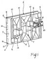
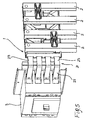
- Figures 1 and 2 are perspective views, respectively a front view and a rear view, illustrating some components of the device according to the invention;
- Figure 3 is a perspective view illustrating the rear part of one of the components of Figure 2 coupled to an elastic element;
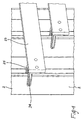
- Figure 4 is a detailed perspective view illustrating means for connection of the device coupled to a busbar; and
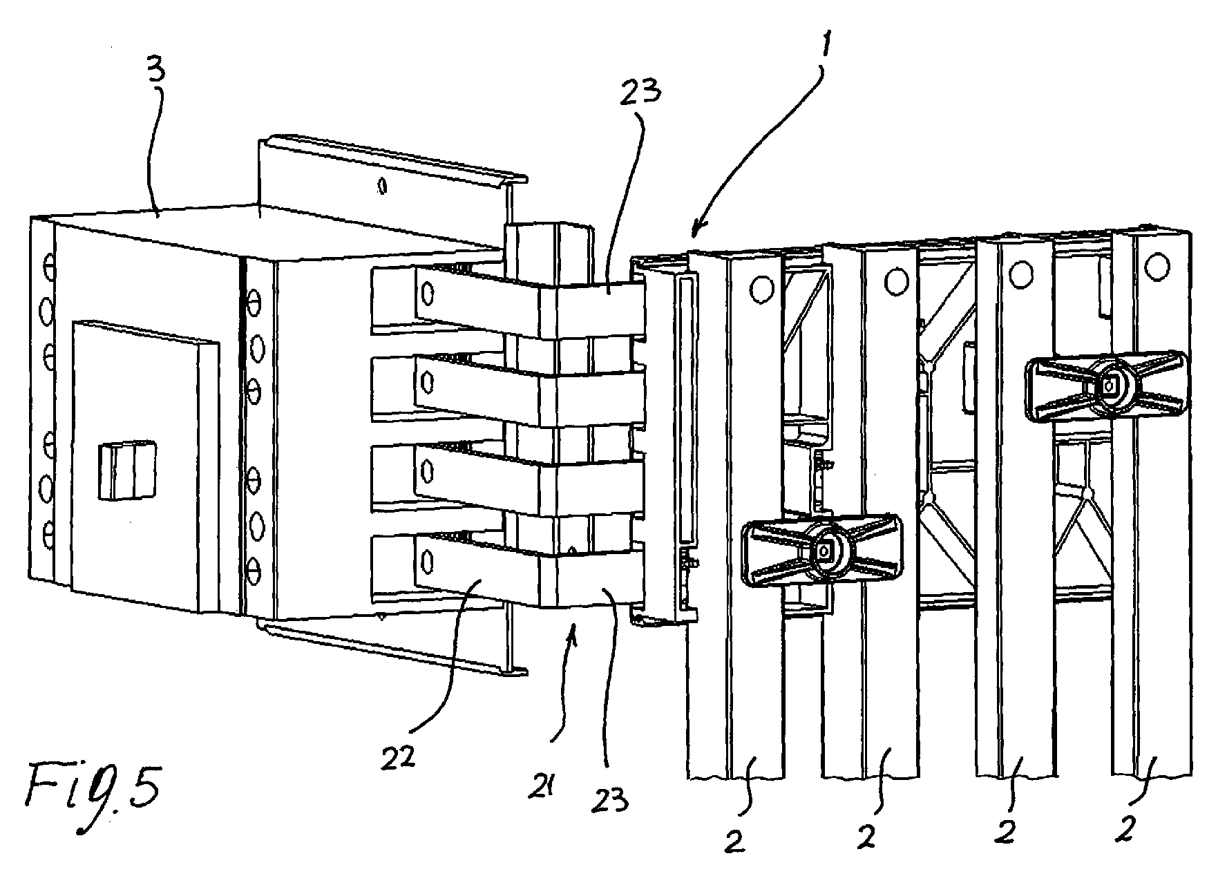
- Figure 5 is a perspective view illustrating schematically the device according to the invention connecting a system of busbars to an apparatus of an electrical switchboard.
- With reference to the figures referred to above, the device according to the invention, designated as a whole in Figure 5 by the reference number 1, comprises means of mechanical coupling with a plurality of bars, designated in Figures 4 and 5 by the
reference number 2, and connection means which are operatively coupled to the coupling means so as to enable direct electrical connection between thebars 2 and at least one apparatus of an electrical switchboard; said apparatus is, for example, typically constituted by a power switch, designated in Figure 5 by thereference number 3. - As illustrated in Figures 1-3, the mechanical-coupling means comprise at least one
first element 4 made of electrically insulating material, for example thermoplastic or thermosetting material. Saidelement 4 has a shaped body, for example substantially parallelepipedal, having abottom face 5, atop face 6, a front face 7, a rear face 8, and two side faces 9. - Advantageously, on the
element 4 there are definedhousing seats 10, designed to couple each with acorresponding bar 2, thus keeping the bars isolated from one another. Preferably, saidhousing seats 10 are arranged on the front face 7 along the line joining thebottom face 5 and thetop face 6, at a predefined distance, e.g., at a constant pitch, and substantially parallel to one another. Between theseats 10 there can preferably be provided ribbings 26 for structural strengthening (see in the figures BN). Furthermore, as may be seen in detail in Figure 3, the firstinsulating element 4 is provided with a plurality oflongitudinal grooves 11, defined on the rear face 8 along the line joining the twoside faces 9. In particular, saidgrooves 11 are arranged parallel and separate from one another, with one end open in an area corresponding to the edge of one of the twoside walls 9, and are in number equal to thehousing seats 10, in the case in point four. - On the
first element 4 there is moreover defined a plurality of throughopenings 12, for example of a rectangular shape, as illustrated in Figure 1, once again equal in number to theseats 10 andgrooves 11. Each of said throughopenings 12 is set along the development of acorresponding housing seat 10 and sets saidseat 10 in communication with a correspondinglongitudinal groove 11. Furthermore, theopenings 12 are arranged along therespective seats 10 at different distances from the bottom wall 7 or the top wall 8. - Preferably, on the
insulating element 4 there is made at least one first throughhole 13, set along the line joining the front face 7 and therear face 9 and having edges projecting from both of thefaces 7 and 9, which define a housing seat for the purposes and functions that will emerge more clearly from the ensuing description. In the embodiment illustrated there are, for example, provided twoholes 13, as illustrated in Figure 3. - In a particularly preferred embodiment, the mechanical-coupling means comprise retention and protection means operatively coupled to the
first element 4 so as to favour its coupling and its withholding in a protected position with the connection means and with thebars 2. - Said retention and protection means comprise a
second element 14, which is also made of insulating material, for example thermoplastic or thermosetting material, designed to be coupled to the firstinsulating element 4 on the rear face 8. Saidsecond element 14 has, viewed laterally, a substantially U-shaped configuration with the two side branches having the free edges shaped so as to presentsurfaces 15 for clamping withsurfaces 16 accordingly mated defined along two opposite edges of the rear face 8. In turn, the central branch is provided with at least one throughhole 17, which is to be aligned with athrough hole 13. In the embodiment illustrated, there are provided two through holes 17 (in Figure 2, one of the twoholes 17 is covered by an element 19), each of which is to be aligned with a corresponding throughhole 13. On the central branch of theelement 14 there may moreover be provided strengthening ribbings 27. - In a preferred embodiment, the retention and protection means further comprise: at least one
elastic means 18, for example a spring, designed to be inserted into the seat defined by the rear edges of the throughhole 13; at least one screw-shapedinsulating element 19, designed to be inserted into the two aligned throughholes planar development 20, which is to be fixed to the free end of thescrew element 19 and is preferably provided with strengthening ribbings 28 on the front face. In the embodiment illustrated (Figures 3 and 5), there are provided twosprings 18, twoscrew elements 19, and twoplane bodies 20 associated thereto. - Advantageously, in the device 1 according to the invention, the connection means comprise a
shaped element 21 made of electrically conductive material and having at least one first end surface for direct electrical connection to theapparatus 3, one second surface for mechanical coupling with the firstinsulating element 11, and one third surface, which can be coupled directly both electrically and mechanically to a corresponding bar. In the embodiment illustrated, theconductive element 21 has: a first preferably substantially L-shaped portion, of which afirst branch 22 has a free end, designed to be inserted directly in a coupling seat of theelectrical apparatus 3, whilst thesecond branch 23 is designed to be positioned within a correspondinglongitudinal groove 11 of the first insulating element. Advantageously, the shapedconductive element 21 has a second substantially pincer-shapedconductive element 24, which extends transversely from thesecond branch 23 of the L-shaped portion. - Said pincer-
shaped portion 24 is designed to be inserted in one of thethrough openings 12 and to grip acorresponding bar 2, as illustrated in Figure 4. The pincer-shaped portion 24 is preferably provided, in a median area from which there branch off the two pincers, with a longitudinal notch, designed to provide it with characteristics of elastic deformability so as to facilitate gripping with thebars 2. - Finally, there is preferably provided an
elastic element 25 mounted on the pincer-shaped portion 24 so as to favour its clamping by pressure on thebar 2. - In practice, in the assembly stage, the
insulating element 4 is directly connected to the bars, by insertion of eachbar 2 in acorresponding coupling seat 10. Aconductive element 21 is coupled to theinsulating element 4, with thebranch 23 of the L-shaped portion inserted in alongitudinal groove 11, and the pincer-shaped body 24 that is inserted in a throughopening 12 and thus grips thecorresponding bar 2, so clamping it. In particular, as illustrated in Figure 5,conductive elements 21 are used in a number equal to that of the bars. Eachelement 21 is inserted, with itsown branch 23, into agroove 11 and with thepincer 24 which is then inserted into thecorresponding opening 12, so gripping therespective bar 2. Saidelements 21 differ from one another simply in the different length of thebranch 23 according to thegroove 11 in which they are inserted. Thebranches 23 extend externally from thegrooves 11 in such a way that the free edges of thebranches 22 are inserted directly into the corresponding terminals for connection of theswitch 3, as illustrated in Figure 5. In turn, theelement 14 is coupled to theelement 4, so clamping together therespective surfaces element 14 covers the rear part of theelement 4, closing thelongitudinal grooves 11 at the top and insulating the rear parts of theelements 21, with the two throughholes 17 that are aligned to the two corresponding throughholes 13. - Each
screw body 19 is inserted into the two aligned holes 13-17, then coming out from the front face 7. At the free end of eachelement 19 there is then fixed the respectiveinsulating plane body 20. By gripping theelement 19, there is in practice obtained gripping of the latter on thesecond element 14 by countering the action of thespring 18 previously inserted into the seat defined by the projecting edges of thehole 13. By virtue of gripping, thanks to the combined action of thespring 18 and of thescrew body 19 that work in mutual antagonism, there is a pulling effect, which, on the one hand, presses theelement 14 in the direction of theelement 4, and on the other pulls thebody 20 so that it rests in the direction of a pair of adjacent bars. In this way, there is obtained a "packed" set in the desired coupling position and providing protection on one side, thanks to theelement 14, and on the other thanks to the action of thespring 18/screw body 19 and theplane element 20, which in practice constitute a safety key. - It has in practice been found that the device according to the invention, thanks to the innovative structure and functionality of its parts, fully accomplishes the pre-set task by providing a series of advantages as compared to the known art. In fact, as previously described, the device 1 is obtained by means of a kit of components which, when assembled, constitute as a whole a single functional block such as to provide simultaneously direct electrical and mechanical coupling between the parts, according to a solution that is simple from the constructional standpoint, is functionally effective, and facilitates considerably assembly as compared to the solutions of the known art. In particular, decidedly simplified is the electrical connection to the equipment, typically the switches, thanks to fact that the part that conducts the current from the bars, typically the
element 21, is inserted directly into the respective terminal of the switch in such a way that for final connection, nothing else remains for the operator to do but to screw the corresponding terminal, without having to use any additional components. Likewise, also the connection to the bars is obtained in a direct and secure way via direct clamping of the pincer-shapedbody 24 and without any intermediate components or additional operations of assembly. Further benefits are achieved from the standpoint of protection and safety, since the device 1 can integrate, in its structure, elements that are able to provide functions of protection, both in the rear part of the area of coupling with the bars and in the front part, in which an anti-tampering key system is obtained, thus rendering the interventions of maintenance safer. Finally, the configuration that is obtained is extremely compact, enabling optimal exploitation of the spaces available so as to make available space for other components or reduce the overall dimensions of the cabinet of the switchboard. - Clearly, what has been described previously for the connection of the system of
bars 2 to just one apparatus can be used in an altogether similar manner when an electrical switchboard, as is usually the case, comprises a number of apparatuses, for example different types of switches, each of which is to be connected to the bars. In this case, it is sufficient to use a number of devices 1, positioned along the development of the bars and mounted according to what has been described previously so as to connect the bars to each single apparatus. A further subject of the present invention is therefore represented by a low-voltage electrical switchboard, characterized in that it comprises one or more connection devices 1 of the type described previously. - The device thus devised may undergo numerous modifications and variations, all falling within the scope of the inventive idea; moreover, all the items may be replaced by other technically equivalent elements. For instance, the shaping and/or positioning and/or number of the various seats or grooves or holes or other parts, as likewise the shaping, for example, of the
elements - In practice, the materials, as well as the dimensions, may be any whatsoever according to the requirements and the state of the art.
Claims (13)
- A device for connection of a plurality of busbars to at least one apparatus of an electrical switchboard, characterized in that it comprises:means of mechanical coupling with said bars, said mechanical-coupling means comprising at least one first element made of insulating material having a shaped body, on which there are defined housing seats, designed to couple each with corresponding bars, insulating them from one another;connection means, operatively coupled to said first element so as to enable direct electrical connection between said bars and said apparatus.
- The device according to Claim 1, characterized in that said coupling means comprise retention and protection means, operatively coupled to said first element so as to favour its coupling and its withholding in a protected position with said connection means and with the bars.
- The device according to Claim 1, characterized in that said first insulating element has a substantially parallelepipedal body having a bottom face, a top face, a front face, a rear face, and two side faces, said housing seats being arranged on said front face along the line joining said bottom and top faces, at a predefined distance from one another.
- The device according to Claim 3, characterized in that said first insulating element is provided with a plurality of longitudinal grooves defined on said rear face along the line joining the two side faces.
- The device according to Claim 4, characterized in that on said first element there is defined a plurality of through openings, each through opening setting a housing seat in communication with a corresponding longitudinal groove.
- The device according to one or more of the preceding claims, characterized in that on said insulating element there is defined at least one first through hole set along the line joining the front and rear faces.
- The device according to one or more of the preceding claims, characterized in that said retention and protection means comprise a second element made of insulating material, designed to be coupled to the first insulating element on the rear face, said second element having a substantially U-shaped configuration with the two side branches having the free edges shaped so as to present surfaces for clamping with accordingly mating surfaces, defined along two edges of the rear face, the central branch being designed to cover said longitudinal grooves at the top and being provided with at least one second through hole, which is to be aligned with said first through hole.
- The device according to one or more of the preceding claims, characterized in that said retention and protection means comprise at least one elastic means, designed to be inserted in said first through hole, a screw-shaped insulating element, designed to be inserted in said first and second through holes and to be gripped on the central branch of the second element in antagonism with said elastic means, and a substantially flat insulating body, designed to be fixed to the free end of said screw element so as to be pulled so that it rests on a pair of adjacent bars during gripping.
- The device according to Claim 1, characterized in that said connection means comprise a shaped element made of conductive material and having at least one first end surface for direct electrical connection to said apparatus, one second surface for mechanical coupling to said first insulating element, and one third surface, which is designed for direct electro-mechanical coupling to a corresponding bar.
- The device according to Claim 9, characterized in that said conductive element has a first substantially L-shaped portion, a first branch of said L having a free end, designed to be inserted directly in a coupling seat of the electrical apparatus, the second branch being designed to be inserted within a corresponding longitudinal groove of the first insulating element.
- The device according to Claim 10, characterized in that said shaped conductive element has a second substantially pincer-shaped conductive element, which extends transversely from the second branch of the first L-shaped portion, said pincer-shaped portion being designed to be inserted in one of said through openings of the first insulating element and to grip a corresponding bar.
- The device according to Claim 11, characterized in that it comprises an elastic element mounted on said pincer-shaped portion so as to favour its gripping by pressure on the bar.
- A low-voltage electrical switchboard, characterized in that it comprises at least one connection device according to one or more of the preceding claims.
Applications Claiming Priority (2)
| Application Number | Priority Date | Filing Date | Title |
|---|---|---|---|
| ITBG20030059 | 2003-12-17 | ||
| IT000059A ITBG20030059A1 (en) | 2003-12-17 | 2003-12-17 | CONNECTION DEVICE FOR CONDUTTRIC BARS TO APPLIANCES OF AN ELECTRIC PANEL. |
Publications (2)
| Publication Number | Publication Date |
|---|---|
| EP1544971A1 true EP1544971A1 (en) | 2005-06-22 |
| EP1544971B1 EP1544971B1 (en) | 2014-08-13 |
Family
ID=34509411
Family Applications (1)
| Application Number | Title | Priority Date | Filing Date |
|---|---|---|---|
| EP04078359.9A Expired - Lifetime EP1544971B1 (en) | 2003-12-17 | 2004-12-10 | Busbar adapter |
Country Status (4)
| Country | Link |
|---|---|
| US (1) | US7121856B2 (en) |
| EP (1) | EP1544971B1 (en) |
| CN (1) | CN1638222B (en) |
| IT (1) | ITBG20030059A1 (en) |
Families Citing this family (7)
| Publication number | Priority date | Publication date | Assignee | Title |
|---|---|---|---|---|
| JP4738929B2 (en) * | 2005-07-28 | 2011-08-03 | 株式会社テーアンテー | Insulation structure between bus bars for vehicle interior lights |
| US7367830B2 (en) * | 2006-03-07 | 2008-05-06 | Eaton Corporation | Busway fitting with switch mounted perpendicular to primary axis |
| US8014131B2 (en) * | 2008-02-05 | 2011-09-06 | Siemens Industry, Inc. | Riser bus bar positioning block |
| DE102008026507A1 (en) * | 2008-05-23 | 2009-11-26 | August Schmid | Closed busbar system for low voltage distribution |
| ITBG20090030A1 (en) * | 2009-05-28 | 2010-11-29 | Abb Spa | DEVICE FOR THE CONNECTION OF AN ELECTRIC LINE TO A SWITCH. |
| US8547684B2 (en) * | 2009-12-17 | 2013-10-01 | Schneider Electric USA, Inc. | Panelboard having a parallel feeder bars distribution |
| US10236664B2 (en) * | 2015-08-17 | 2019-03-19 | Siemens Industry, Inc. | Feed thru main breaker apparatus, systems and methods |
Citations (5)
| Publication number | Priority date | Publication date | Assignee | Title |
|---|---|---|---|---|
| EP0594544A1 (en) * | 1992-10-19 | 1994-04-27 | Bticino S.P.A. | An adapter for connecting a multi-phase box-shaped switch to parallel bus-bars |
| DE19506056A1 (en) * | 1995-02-22 | 1996-08-29 | Peterreins Schalttechnik Gmbh | Insulated adaptor plate for mounting on multiphase bus=bar system |
| DE19807990C1 (en) * | 1998-02-26 | 2000-01-05 | Peterreins Schalttechnik Gmbh | Adapter device for attachment to current rails of multiple phase system |
| US6113439A (en) * | 1997-12-15 | 2000-09-05 | Rittal-Werk Rudolf Loh Gmbh & Co. Kg | Adapter with a base housing for a bus bar system having a number of bus bars |
| DE10215500A1 (en) * | 2002-04-09 | 2003-10-23 | Efen Gmbh | Adapter for putting switching device on bus bars, has current bridge, hook attached to upper part, upper and lower parts joined by latching elements; hook actuation element can be operated externally |
Family Cites Families (5)
| Publication number | Priority date | Publication date | Assignee | Title |
|---|---|---|---|---|
| US4916574A (en) * | 1989-06-06 | 1990-04-10 | Siemens Energy & Automation, Inc. | Panelboard bus bar arrangement |
| US5162616A (en) * | 1991-02-15 | 1992-11-10 | Precision Connector Designs, Inc. | Bus bar assembly |
| US6142807A (en) * | 1998-10-02 | 2000-11-07 | Siemens Energy & Automation, Inc. | High current and low current electrical busway systems having compatible bus plug |
| WO2000027008A1 (en) * | 1998-10-30 | 2000-05-11 | Abb Ricerca S.P.A. | Device for supporting and fixing bus-bars |
| US6361333B1 (en) * | 2000-05-08 | 2002-03-26 | Ronald G. Cash, Jr. | Electrical junction box |
-
2003
- 2003-12-17 IT IT000059A patent/ITBG20030059A1/en unknown
-
2004
- 2004-12-10 EP EP04078359.9A patent/EP1544971B1/en not_active Expired - Lifetime
- 2004-12-17 US US11/013,714 patent/US7121856B2/en not_active Expired - Lifetime
- 2004-12-17 CN CN2004101046808A patent/CN1638222B/en not_active Expired - Fee Related
Patent Citations (5)
| Publication number | Priority date | Publication date | Assignee | Title |
|---|---|---|---|---|
| EP0594544A1 (en) * | 1992-10-19 | 1994-04-27 | Bticino S.P.A. | An adapter for connecting a multi-phase box-shaped switch to parallel bus-bars |
| DE19506056A1 (en) * | 1995-02-22 | 1996-08-29 | Peterreins Schalttechnik Gmbh | Insulated adaptor plate for mounting on multiphase bus=bar system |
| US6113439A (en) * | 1997-12-15 | 2000-09-05 | Rittal-Werk Rudolf Loh Gmbh & Co. Kg | Adapter with a base housing for a bus bar system having a number of bus bars |
| DE19807990C1 (en) * | 1998-02-26 | 2000-01-05 | Peterreins Schalttechnik Gmbh | Adapter device for attachment to current rails of multiple phase system |
| DE10215500A1 (en) * | 2002-04-09 | 2003-10-23 | Efen Gmbh | Adapter for putting switching device on bus bars, has current bridge, hook attached to upper part, upper and lower parts joined by latching elements; hook actuation element can be operated externally |
Also Published As
| Publication number | Publication date |
|---|---|
| CN1638222A (en) | 2005-07-13 |
| US20050136719A1 (en) | 2005-06-23 |
| EP1544971B1 (en) | 2014-08-13 |
| CN1638222B (en) | 2012-05-02 |
| US7121856B2 (en) | 2006-10-17 |
| ITBG20030059A1 (en) | 2005-06-18 |
Similar Documents
| Publication | Publication Date | Title |
|---|---|---|
| US5094626A (en) | Set of assembly elements intended to facilitate concurrent electrical connection of a plurality of modular automatic circuit breakers | |
| US7909663B1 (en) | Modular optimized plug-in jaw | |
| US5408154A (en) | Motor connection block, particularly for electric motors | |
| US6663441B1 (en) | Electric switch appliance and quick-assembly | |
| CN111326872B (en) | Conductors for power distribution systems | |
| CN117060304B (en) | Detachable integrated power distribution system | |
| KR100595343B1 (en) | Upgradeable feeder function for low-voltage electric cubicle | |
| US7619902B2 (en) | Connection module for a power switch | |
| EP1544971B1 (en) | Busbar adapter | |
| CN109193443A (en) | Distribution system and its assemble method including neutral point attachment device | |
| US7247045B1 (en) | Modular connection assembly | |
| EP0673081B1 (en) | Terminal box | |
| EP2124303A1 (en) | Adapter, adapter in combination with an MCCB for a low voltage switchboard, use of such adapter and an electric switchboard comprising such adapter | |
| EP0108868B1 (en) | Current connecting device for the establishing of electrical connection between conductors | |
| EP0975079B1 (en) | Electrical installation distributor | |
| US20240114645A1 (en) | Modular and scalable power distribution | |
| US20250087914A1 (en) | Terminal block with screwless terminals | |
| US10297985B2 (en) | Modular electrical devices and methods for assembling and mounting the same | |
| EP0880208A1 (en) | Modular wiring unit | |
| EP2020669A1 (en) | Electrical connection auxiliary module for circuit breakers. | |
| JP3414259B2 (en) | Connection conversion adapter | |
| US20230209763A1 (en) | Modular and scalable power distribution | |
| EP3817163B1 (en) | Conductor assembly for a power distribution system | |
| KR200323651Y1 (en) | Plug in brush docking unit | |
| GB2534615A (en) | A creepage protection assembly and a panel box/cabinet comprising the assembly |
Legal Events
| Date | Code | Title | Description |
|---|---|---|---|
| PUAI | Public reference made under article 153(3) epc to a published international application that has entered the european phase |
Free format text: ORIGINAL CODE: 0009012 |
|
| AK | Designated contracting states |
Kind code of ref document: A1 Designated state(s): AT BE BG CH CY CZ DE DK EE ES FI FR GB GR HU IE IS IT LI LT LU MC NL PL PT RO SE SI SK TR |
|
| AX | Request for extension of the european patent |
Extension state: AL BA HR LV MK YU |
|
| 17P | Request for examination filed |
Effective date: 20051010 |
|
| AKX | Designation fees paid |
Designated state(s): AT BE BG CH CY CZ DE DK EE ES FI FR GB GR HU IE IS IT LI LT LU MC NL PL PT RO SE SI SK TR |
|
| RAP1 | Party data changed (applicant data changed or rights of an application transferred) |
Owner name: ABB S.P.A. |
|
| 17Q | First examination report despatched |
Effective date: 20120926 |
|
| GRAP | Despatch of communication of intention to grant a patent |
Free format text: ORIGINAL CODE: EPIDOSNIGR1 |
|
| INTG | Intention to grant announced |
Effective date: 20140307 |
|
| GRAS | Grant fee paid |
Free format text: ORIGINAL CODE: EPIDOSNIGR3 |
|
| GRAA | (expected) grant |
Free format text: ORIGINAL CODE: 0009210 |
|
| AK | Designated contracting states |
Kind code of ref document: B1 Designated state(s): AT BE BG CH CY CZ DE DK EE ES FI FR GB GR HU IE IS IT LI LT LU MC NL PL PT RO SE SI SK TR |
|
| REG | Reference to a national code |
Ref country code: GB Ref legal event code: FG4D |
|
| REG | Reference to a national code |
Ref country code: CH Ref legal event code: EP Ref country code: AT Ref legal event code: REF Ref document number: 682704 Country of ref document: AT Kind code of ref document: T Effective date: 20140815 |
|
| REG | Reference to a national code |
Ref country code: IE Ref legal event code: FG4D |
|
| REG | Reference to a national code |
Ref country code: DE Ref legal event code: R096 Ref document number: 602004045620 Country of ref document: DE Effective date: 20140925 |
|
| REG | Reference to a national code |
Ref country code: NL Ref legal event code: VDEP Effective date: 20140813 |
|
| REG | Reference to a national code |
Ref country code: AT Ref legal event code: MK05 Ref document number: 682704 Country of ref document: AT Kind code of ref document: T Effective date: 20140813 |
|
| REG | Reference to a national code |
Ref country code: LT Ref legal event code: MG4D |
|
| PG25 | Lapsed in a contracting state [announced via postgrant information from national office to epo] |
Ref country code: FI Free format text: LAPSE BECAUSE OF FAILURE TO SUBMIT A TRANSLATION OF THE DESCRIPTION OR TO PAY THE FEE WITHIN THE PRESCRIBED TIME-LIMIT Effective date: 20140813 Ref country code: ES Free format text: LAPSE BECAUSE OF FAILURE TO SUBMIT A TRANSLATION OF THE DESCRIPTION OR TO PAY THE FEE WITHIN THE PRESCRIBED TIME-LIMIT Effective date: 20140813 Ref country code: SE Free format text: LAPSE BECAUSE OF FAILURE TO SUBMIT A TRANSLATION OF THE DESCRIPTION OR TO PAY THE FEE WITHIN THE PRESCRIBED TIME-LIMIT Effective date: 20140813 Ref country code: BG Free format text: LAPSE BECAUSE OF FAILURE TO SUBMIT A TRANSLATION OF THE DESCRIPTION OR TO PAY THE FEE WITHIN THE PRESCRIBED TIME-LIMIT Effective date: 20141113 Ref country code: PT Free format text: LAPSE BECAUSE OF FAILURE TO SUBMIT A TRANSLATION OF THE DESCRIPTION OR TO PAY THE FEE WITHIN THE PRESCRIBED TIME-LIMIT Effective date: 20141215 Ref country code: GR Free format text: LAPSE BECAUSE OF FAILURE TO SUBMIT A TRANSLATION OF THE DESCRIPTION OR TO PAY THE FEE WITHIN THE PRESCRIBED TIME-LIMIT Effective date: 20141114 Ref country code: LT Free format text: LAPSE BECAUSE OF FAILURE TO SUBMIT A TRANSLATION OF THE DESCRIPTION OR TO PAY THE FEE WITHIN THE PRESCRIBED TIME-LIMIT Effective date: 20140813 |
|
| PGFP | Annual fee paid to national office [announced via postgrant information from national office to epo] |
Ref country code: GB Payment date: 20141219 Year of fee payment: 11 Ref country code: DE Payment date: 20141211 Year of fee payment: 11 |
|
| PG25 | Lapsed in a contracting state [announced via postgrant information from national office to epo] |
Ref country code: AT Free format text: LAPSE BECAUSE OF FAILURE TO SUBMIT A TRANSLATION OF THE DESCRIPTION OR TO PAY THE FEE WITHIN THE PRESCRIBED TIME-LIMIT Effective date: 20140813 Ref country code: IS Free format text: LAPSE BECAUSE OF FAILURE TO SUBMIT A TRANSLATION OF THE DESCRIPTION OR TO PAY THE FEE WITHIN THE PRESCRIBED TIME-LIMIT Effective date: 20141213 Ref country code: CY Free format text: LAPSE BECAUSE OF FAILURE TO SUBMIT A TRANSLATION OF THE DESCRIPTION OR TO PAY THE FEE WITHIN THE PRESCRIBED TIME-LIMIT Effective date: 20140813 |
|
| PGFP | Annual fee paid to national office [announced via postgrant information from national office to epo] |
Ref country code: FR Payment date: 20141219 Year of fee payment: 11 |
|
| PG25 | Lapsed in a contracting state [announced via postgrant information from national office to epo] |
Ref country code: NL Free format text: LAPSE BECAUSE OF FAILURE TO SUBMIT A TRANSLATION OF THE DESCRIPTION OR TO PAY THE FEE WITHIN THE PRESCRIBED TIME-LIMIT Effective date: 20140813 |
|
| PG25 | Lapsed in a contracting state [announced via postgrant information from national office to epo] |
Ref country code: EE Free format text: LAPSE BECAUSE OF FAILURE TO SUBMIT A TRANSLATION OF THE DESCRIPTION OR TO PAY THE FEE WITHIN THE PRESCRIBED TIME-LIMIT Effective date: 20140813 Ref country code: DK Free format text: LAPSE BECAUSE OF FAILURE TO SUBMIT A TRANSLATION OF THE DESCRIPTION OR TO PAY THE FEE WITHIN THE PRESCRIBED TIME-LIMIT Effective date: 20140813 Ref country code: SK Free format text: LAPSE BECAUSE OF FAILURE TO SUBMIT A TRANSLATION OF THE DESCRIPTION OR TO PAY THE FEE WITHIN THE PRESCRIBED TIME-LIMIT Effective date: 20140813 Ref country code: CZ Free format text: LAPSE BECAUSE OF FAILURE TO SUBMIT A TRANSLATION OF THE DESCRIPTION OR TO PAY THE FEE WITHIN THE PRESCRIBED TIME-LIMIT Effective date: 20140813 Ref country code: RO Free format text: LAPSE BECAUSE OF FAILURE TO SUBMIT A TRANSLATION OF THE DESCRIPTION OR TO PAY THE FEE WITHIN THE PRESCRIBED TIME-LIMIT Effective date: 20140813 |
|
| PGFP | Annual fee paid to national office [announced via postgrant information from national office to epo] |
Ref country code: IT Payment date: 20141218 Year of fee payment: 11 |
|
| REG | Reference to a national code |
Ref country code: DE Ref legal event code: R097 Ref document number: 602004045620 Country of ref document: DE |
|
| PG25 | Lapsed in a contracting state [announced via postgrant information from national office to epo] |
Ref country code: PL Free format text: LAPSE BECAUSE OF FAILURE TO SUBMIT A TRANSLATION OF THE DESCRIPTION OR TO PAY THE FEE WITHIN THE PRESCRIBED TIME-LIMIT Effective date: 20140813 |
|
| PLBE | No opposition filed within time limit |
Free format text: ORIGINAL CODE: 0009261 |
|
| STAA | Information on the status of an ep patent application or granted ep patent |
Free format text: STATUS: NO OPPOSITION FILED WITHIN TIME LIMIT |
|
| PG25 | Lapsed in a contracting state [announced via postgrant information from national office to epo] |
Ref country code: BE Free format text: LAPSE BECAUSE OF NON-PAYMENT OF DUE FEES Effective date: 20141231 |
|
| 26N | No opposition filed |
Effective date: 20150515 |
|
| PG25 | Lapsed in a contracting state [announced via postgrant information from national office to epo] |
Ref country code: LU Free format text: LAPSE BECAUSE OF FAILURE TO SUBMIT A TRANSLATION OF THE DESCRIPTION OR TO PAY THE FEE WITHIN THE PRESCRIBED TIME-LIMIT Effective date: 20141210 |
|
| REG | Reference to a national code |
Ref country code: CH Ref legal event code: PL |
|
| REG | Reference to a national code |
Ref country code: IE Ref legal event code: MM4A |
|
| PG25 | Lapsed in a contracting state [announced via postgrant information from national office to epo] |
Ref country code: LI Free format text: LAPSE BECAUSE OF NON-PAYMENT OF DUE FEES Effective date: 20141231 Ref country code: CH Free format text: LAPSE BECAUSE OF NON-PAYMENT OF DUE FEES Effective date: 20141231 Ref country code: IE Free format text: LAPSE BECAUSE OF NON-PAYMENT OF DUE FEES Effective date: 20141210 |
|
| PG25 | Lapsed in a contracting state [announced via postgrant information from national office to epo] |
Ref country code: SI Free format text: LAPSE BECAUSE OF FAILURE TO SUBMIT A TRANSLATION OF THE DESCRIPTION OR TO PAY THE FEE WITHIN THE PRESCRIBED TIME-LIMIT Effective date: 20140813 |
|
| PG25 | Lapsed in a contracting state [announced via postgrant information from national office to epo] |
Ref country code: MC Free format text: LAPSE BECAUSE OF FAILURE TO SUBMIT A TRANSLATION OF THE DESCRIPTION OR TO PAY THE FEE WITHIN THE PRESCRIBED TIME-LIMIT Effective date: 20140813 |
|
| REG | Reference to a national code |
Ref country code: DE Ref legal event code: R119 Ref document number: 602004045620 Country of ref document: DE |
|
| PG25 | Lapsed in a contracting state [announced via postgrant information from national office to epo] |
Ref country code: HU Free format text: LAPSE BECAUSE OF FAILURE TO SUBMIT A TRANSLATION OF THE DESCRIPTION OR TO PAY THE FEE WITHIN THE PRESCRIBED TIME-LIMIT; INVALID AB INITIO Effective date: 20041210 Ref country code: TR Free format text: LAPSE BECAUSE OF FAILURE TO SUBMIT A TRANSLATION OF THE DESCRIPTION OR TO PAY THE FEE WITHIN THE PRESCRIBED TIME-LIMIT Effective date: 20140813 Ref country code: BE Free format text: LAPSE BECAUSE OF FAILURE TO SUBMIT A TRANSLATION OF THE DESCRIPTION OR TO PAY THE FEE WITHIN THE PRESCRIBED TIME-LIMIT Effective date: 20140813 |
|
| GBPC | Gb: european patent ceased through non-payment of renewal fee |
Effective date: 20151210 |
|
| REG | Reference to a national code |
Ref country code: FR Ref legal event code: ST Effective date: 20160831 |
|
| PG25 | Lapsed in a contracting state [announced via postgrant information from national office to epo] |
Ref country code: DE Free format text: LAPSE BECAUSE OF NON-PAYMENT OF DUE FEES Effective date: 20160701 Ref country code: GB Free format text: LAPSE BECAUSE OF NON-PAYMENT OF DUE FEES Effective date: 20151210 |
|
| PG25 | Lapsed in a contracting state [announced via postgrant information from national office to epo] |
Ref country code: FR Free format text: LAPSE BECAUSE OF NON-PAYMENT OF DUE FEES Effective date: 20151231 |
|
| PG25 | Lapsed in a contracting state [announced via postgrant information from national office to epo] |
Ref country code: IT Free format text: LAPSE BECAUSE OF NON-PAYMENT OF DUE FEES Effective date: 20151210 |