EP1544868A1 - Flexible cable for power transmission - Google Patents
Flexible cable for power transmission Download PDFInfo
- Publication number
- EP1544868A1 EP1544868A1 EP03380290A EP03380290A EP1544868A1 EP 1544868 A1 EP1544868 A1 EP 1544868A1 EP 03380290 A EP03380290 A EP 03380290A EP 03380290 A EP03380290 A EP 03380290A EP 1544868 A1 EP1544868 A1 EP 1544868A1
- Authority
- EP
- European Patent Office
- Prior art keywords
- flexible cable
- electricity
- join
- transmission
- cable
- Prior art date
- Legal status (The legal status is an assumption and is not a legal conclusion. Google has not performed a legal analysis and makes no representation as to the accuracy of the status listed.)
- Withdrawn
Links
- 230000005540 biological transmission Effects 0.000 title claims abstract description 12
- 239000004020 conductor Substances 0.000 claims abstract description 18
- 230000005611 electricity Effects 0.000 claims abstract description 11
- 239000012528 membrane Substances 0.000 claims description 9
- 229920000915 polyvinyl chloride Polymers 0.000 description 5
- 239000004800 polyvinyl chloride Substances 0.000 description 5
- 239000000463 material Substances 0.000 description 4
- 229920003023 plastic Polymers 0.000 description 4
- 239000004033 plastic Substances 0.000 description 4
- 238000009413 insulation Methods 0.000 description 2
- 230000015572 biosynthetic process Effects 0.000 description 1
- 230000015556 catabolic process Effects 0.000 description 1
- 150000001875 compounds Chemical class 0.000 description 1
- 238000010616 electrical installation Methods 0.000 description 1
- 238000009434 installation Methods 0.000 description 1
- 239000011810 insulating material Substances 0.000 description 1
Images
Classifications
-
- H—ELECTRICITY
- H01—ELECTRIC ELEMENTS
- H01B—CABLES; CONDUCTORS; INSULATORS; SELECTION OF MATERIALS FOR THEIR CONDUCTIVE, INSULATING OR DIELECTRIC PROPERTIES
- H01B7/00—Insulated conductors or cables characterised by their form
- H01B7/40—Insulated conductors or cables characterised by their form with arrangements for facilitating mounting or securing
Definitions
- This invention relates to a flexible cable for the transmission of electricity.
- the main object of this invention lies in the development of a new type of flexible cable, comprising "n" conductors 1 which are individually insulated and linked together by a low-strength join made of the same insulating material.
- "n" conductors 1 which are individually insulated and linked together by a low-strength join made of the same insulating material.
- the cable concerned is a cable with individual flexible conductors 1 insulated with PVC (polyvinyl chloride) or another plastic material with similar or better quality characteristics, comprising 3, 4, 5 or "n" conductors, with rated alternating-current voltages of 330 V / 500 V or above, as allowed by the regulations, for use in industrial installations and in buildings in which an additional mechanical protection system is used, such as cable trays or ducts.
- PVC polyvinyl chloride
- Each of these conductors complies with standard IRAM 2183/91 and belongs to a flexible formation that may be of class 4 or class 5.
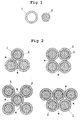
- Figures 2 and 3 show cut-away examples of the various ways in the which said join "a” may be arranged, the parts in black 1 being the insulation in PVC or another plastic material with similar or better quality characteristics, and the central part 2 being the conductor itself - Fig. 1.
Landscapes
- Installation Of Indoor Wiring (AREA)
Abstract
Description
- This invention relates to a flexible cable for the transmission of electricity.
- This is a new compound flexible cable, insulated with PVC or another plastic material with similar or better quality characteristics, for use in electrical installations and in buildings.
- The main object of this invention lies in the development of a new type of flexible cable, comprising "n"
conductors 1 which are individually insulated and linked together by a low-strength join made of the same insulating material. When used in conjunction with the additional mechanical-protection system adopted - cable duct or tray - this new type of cable affords better use of the space available, on account of its orderly layout. - To aid understanding of this invention and to make it clearer, the cable of this invention is illustrated in a number of figures, in which:
- Figure 1 is a cut-away view showing the breakdown of the two parts that make up the basic individual conductor.
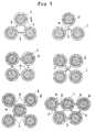
- Figure 2 is a set of views showing variations in the grouping of a number of basic conductors linked together by a tangential join between the various insulating sheathes.
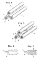
- Figure 3 is another set of views also showing groupings of basic conductors, though here linked together using intermediate membranes.
- Figure 4 is a perspective view of one example of a continuous join using membranes.
- Figure 5 is a variant of the same example seen in Figure 4, with the membrane divided into spaced lengths.
- Figure 6 is a perspective view of a length of single-piece homogeneous membrane for the join, as an example for three basic conductors.
- Figure 7 shows the same view as Figure 6 but with a variant, the membrane having cut-aways.
- In the Figures, similar or corresponding parts or elements are marked with the same signs.
-
- The cable concerned is a cable with individual
flexible conductors 1 insulated with PVC (polyvinyl chloride) or another plastic material with similar or better quality characteristics, comprising 3, 4, 5 or "n" conductors, with rated alternating-current voltages of 330 V / 500 V or above, as allowed by the regulations, for use in industrial installations and in buildings in which an additional mechanical protection system is used, such as cable trays or ducts. - These "n" conductors run in parallel alongside each other, and are linked by a low-strength join "a" in PVC or another plastic material with similar or better quality characteristics, thus linking the individual insulation covers of the conductors together.
- Each of these conductors complies with standard IRAM 2183/91 and belongs to a flexible formation that may be of class 4 or class 5.
- Figures 2 and 3 show cut-away examples of the various ways in the which said join "a" may be arranged, the parts in black 1 being the insulation in PVC or another plastic material with similar or better quality characteristics, and the
central part 2 being the conductor itself - Fig. 1. - The linking between the various individual basic conductors may be arranged in various ways:
- 1.- Join "a" of the tangential type, as shown in
Figure 2, with the special feature that the join may be
arranged:
- a) continuously all the way along;
- b) in an alternating manner every so-many centimetres, the width and continuity varying.
- 2.- Join "a" with
membrane 3 as illustrated in Figure 3, with the following embodiments: - a) continuously, as shown in the example of Figure 4;
- b) in an alternating manner every so-many centimetres, the width and continuity varying, as shown in the example of Figure 5.
- 3.- An alternating join using points of varying shape, size, width and continuity, as shown for example in the illustration of Figure 5, though with other forms of join.
- 4.- It should be added that the joining
membrane 3 can be: - a) homogeneous, without breaks, as illustrated in Figure 6.
- b) with holes, cut-aways or similar arrangements 3', in various shapes and sizes, repeated as frequently as may be required for the flexibility of the whole (the cable), as illustrated in Figure 7.
-
- It is to be noted that the forms shown by way of example in Figures 4, 5, 6 and 7 correspond to instances of three conductors, and are some of the variants that are possible, though with the clear, specific reservation that any other form of linking, for any number "n" of basic individual conductors, is also covered.
- The forms shown in those Figures may be adopted, or any other as required for the safety and flexibility of the whole.
Claims (9)
- Flexible cable for the transmission of electricity, characterised in that it has at least three individual conductors, each comprising a conducting core that is fully sheathed by an insulating cover of its own, these three conductors all being linked together to make a single whole by means of a join between their sheathes, thus defining the transverse section of the cable.
- Flexible cable for the transmission of electricity, as claimed in claim 1, characterised in that the join between the sheaths is arranged tangentially.
- Flexible cable for the transmission of electricity, as claimed in claim 1, characterised in that the join between the sheaths is arranged using an intermediate membrane.
- Flexible cable for the transmission of electricity, as claimed in any of claims 1 to 3, characterised in that the join is unbroken throughout the full length of the cable.
- Flexible cable for the transmission of electricity, as claimed in any of claims 1 to 3, characterised in that said join is arranged by spaced sectors between those sheaths.
- Flexible cable for the transmission of electricity, as claimed in any of claims 1 to 3, characterised in that said join is arranged by points between those sheaths with intermediate spaces along their length.
- Flexible cable for the transmission of electricity, as claimed in any of claims 1 to 3, characterised in that said join is arranged by spaced lengths between those sheaths.
- Flexible cable for the transmission of electricity, as claimed in any of claims 1 to 3, characterised in that said membrane has holes, cut-aways or other similar arrangements throughout its length.
- Flexible cable for the transmission of electricity, as claimed in any of the above claims, characterised in that said transverse section of all the cables together virtually conforms to a polygonal layout.
Priority Applications (1)
| Application Number | Priority Date | Filing Date | Title |
|---|---|---|---|
| EP03380290A EP1544868A1 (en) | 2003-12-15 | 2003-12-15 | Flexible cable for power transmission |
Applications Claiming Priority (1)
| Application Number | Priority Date | Filing Date | Title |
|---|---|---|---|
| EP03380290A EP1544868A1 (en) | 2003-12-15 | 2003-12-15 | Flexible cable for power transmission |
Publications (1)
| Publication Number | Publication Date |
|---|---|
| EP1544868A1 true EP1544868A1 (en) | 2005-06-22 |
Family
ID=34486521
Family Applications (1)
| Application Number | Title | Priority Date | Filing Date |
|---|---|---|---|
| EP03380290A Withdrawn EP1544868A1 (en) | 2003-12-15 | 2003-12-15 | Flexible cable for power transmission |
Country Status (1)
| Country | Link |
|---|---|
| EP (1) | EP1544868A1 (en) |
Cited By (3)
| Publication number | Priority date | Publication date | Assignee | Title |
|---|---|---|---|---|
| WO2008003970A3 (en) * | 2006-07-05 | 2008-02-28 | Linkranch Ltd | Electrical cable |
| DE102012203316A1 (en) * | 2012-03-02 | 2013-09-05 | Homeway Gmbh | Cable assembly e.g. flexible multi-core flat strip cable assembly installed in building, has free spaces that are provided between connecting webs such that respective adjacent cables are moved mutually |
| EP2333789A4 (en) * | 2007-12-04 | 2013-11-13 | Barrow S R L | Multipolar cable and production method therefor |
Citations (5)
| Publication number | Priority date | Publication date | Assignee | Title |
|---|---|---|---|---|
| BE512151A (en) * | ||||
| CH280298A (en) * | 1948-11-17 | 1952-01-15 | Sprecher & Schuh Ag | Insulated multiple conductor. |
| FR2025952A1 (en) * | 1968-12-12 | 1970-09-11 | Uss Eng & Consult | Insulation assembly for multiple conductor power cable |
| DE2200105A1 (en) * | 1971-06-03 | 1972-12-14 | Oberspree Kabelwerke Veb K | Multi-core cables and wires |
| US20020121389A1 (en) * | 2001-02-23 | 2002-09-05 | Commscope Properties, Llc | Non-continuous connecting web for cable applications |
-
2003
- 2003-12-15 EP EP03380290A patent/EP1544868A1/en not_active Withdrawn
Patent Citations (5)
| Publication number | Priority date | Publication date | Assignee | Title |
|---|---|---|---|---|
| BE512151A (en) * | ||||
| CH280298A (en) * | 1948-11-17 | 1952-01-15 | Sprecher & Schuh Ag | Insulated multiple conductor. |
| FR2025952A1 (en) * | 1968-12-12 | 1970-09-11 | Uss Eng & Consult | Insulation assembly for multiple conductor power cable |
| DE2200105A1 (en) * | 1971-06-03 | 1972-12-14 | Oberspree Kabelwerke Veb K | Multi-core cables and wires |
| US20020121389A1 (en) * | 2001-02-23 | 2002-09-05 | Commscope Properties, Llc | Non-continuous connecting web for cable applications |
Cited By (4)
| Publication number | Priority date | Publication date | Assignee | Title |
|---|---|---|---|---|
| WO2008003970A3 (en) * | 2006-07-05 | 2008-02-28 | Linkranch Ltd | Electrical cable |
| EP2333789A4 (en) * | 2007-12-04 | 2013-11-13 | Barrow S R L | Multipolar cable and production method therefor |
| DE102012203316A1 (en) * | 2012-03-02 | 2013-09-05 | Homeway Gmbh | Cable assembly e.g. flexible multi-core flat strip cable assembly installed in building, has free spaces that are provided between connecting webs such that respective adjacent cables are moved mutually |
| DE102012203316B4 (en) | 2012-03-02 | 2022-05-05 | Homeway Gmbh | cable arrangement |
Similar Documents
| Publication | Publication Date | Title |
|---|---|---|
| US4777325A (en) | Low profile cables for twisted pairs | |
| US5342991A (en) | Flexible hybrid branch cable | |
| KR101843692B1 (en) | Stator | |
| EP3043358B1 (en) | Metal sheathed cable with jacketed, cabled conductor subassembly | |
| US11158440B2 (en) | Capacitive power transmission cable | |
| US5329065A (en) | Electrical cable | |
| US12400772B2 (en) | Capacitive power transmission cable | |
| US6652288B2 (en) | Electrical distribution block | |
| US9959954B1 (en) | Power and control cable for healthcare facilities | |
| WO2021094783A1 (en) | Capacitive power transmission cable | |
| US9431863B2 (en) | Insulation component for an electric machine and method of assembly | |
| EP3244422B1 (en) | Three core power cables with surrounding plastic filler | |
| EP4418480A1 (en) | Shielded busbar | |
| US716155A (en) | Electric cable. | |
| US7825332B1 (en) | Bundled wire device | |
| KR101200616B1 (en) | Structure of stranded conductor for electrical power cable | |
| JP2011210675A (en) | Patch cord for lan | |
| US759981A (en) | Electric cable. | |
| US20240221972A1 (en) | Charging cable with optimized manageability | |
| KR100967735B1 (en) | Twist Feeder for Booth Duct System | |
| AU2019229408B2 (en) | Contact element | |
| EP0116044B1 (en) | Distributing bus-bar | |
| HK40062833A (en) | Layered cable | |
| JPH01105406A (en) | Plate-type power cable and cable line | |
| CN201017712Y (en) | Bundling type branch cable |
Legal Events
| Date | Code | Title | Description |
|---|---|---|---|
| PUAI | Public reference made under article 153(3) epc to a published international application that has entered the european phase |
Free format text: ORIGINAL CODE: 0009012 |
|
| AK | Designated contracting states |
Kind code of ref document: A1 Designated state(s): AT BE BG CH CY CZ DE DK EE ES FI FR GB GR HU IE IT LI LU MC NL PT RO SE SI SK TR |
|
| AX | Request for extension of the european patent |
Extension state: AL LT LV MK |
|
| AKX | Designation fees paid |
Designated state(s): AT BE BG CH CY CZ DE DK EE ES FI FR GB GR HU IE IT LI LU MC NL PT RO SE SI SK TR |
|
| 17P | Request for examination filed |
Effective date: 20060221 |
|
| 17Q | First examination report despatched |
Effective date: 20060825 |
|
| STAA | Information on the status of an ep patent application or granted ep patent |
Free format text: STATUS: THE APPLICATION IS DEEMED TO BE WITHDRAWN |
|
| 18D | Application deemed to be withdrawn |
Effective date: 20070105 |