EP1544699A1 - Verfahren und Einrichtung zur Bewegungsführung eines bewegbaren Maschinenelementes einer Werkzeug- oder Produktionsmaschine - Google Patents
Verfahren und Einrichtung zur Bewegungsführung eines bewegbaren Maschinenelementes einer Werkzeug- oder Produktionsmaschine Download PDFInfo
- Publication number
- EP1544699A1 EP1544699A1 EP04028163A EP04028163A EP1544699A1 EP 1544699 A1 EP1544699 A1 EP 1544699A1 EP 04028163 A EP04028163 A EP 04028163A EP 04028163 A EP04028163 A EP 04028163A EP 1544699 A1 EP1544699 A1 EP 1544699A1
- Authority
- EP
- European Patent Office
- Prior art keywords
- drive
- natural frequency
- setpoints
- machine
- lsoll1
- Prior art date
- Legal status (The legal status is an assumption and is not a legal conclusion. Google has not performed a legal analysis and makes no representation as to the accuracy of the status listed.)
- Granted
Links
Images



Classifications
-
- G—PHYSICS
- G05—CONTROLLING; REGULATING
- G05B—CONTROL OR REGULATING SYSTEMS IN GENERAL; FUNCTIONAL ELEMENTS OF SUCH SYSTEMS; MONITORING OR TESTING ARRANGEMENTS FOR SUCH SYSTEMS OR ELEMENTS
- G05B19/00—Program-control systems
- G05B19/02—Program-control systems electric
- G05B19/18—Numerical control [NC], i.e. automatically operating machines, in particular machine tools, e.g. in a manufacturing environment, so as to execute positioning, movement or co-ordinated operations by means of program data in numerical form
- G05B19/19—Numerical control [NC], i.e. automatically operating machines, in particular machine tools, e.g. in a manufacturing environment, so as to execute positioning, movement or co-ordinated operations by means of program data in numerical form characterised by positioning or contouring control systems, e.g. to control position from one programmed point to another or to control movement along a programmed continuous path
-
- G—PHYSICS
- G05—CONTROLLING; REGULATING
- G05B—CONTROL OR REGULATING SYSTEMS IN GENERAL; FUNCTIONAL ELEMENTS OF SUCH SYSTEMS; MONITORING OR TESTING ARRANGEMENTS FOR SUCH SYSTEMS OR ELEMENTS
- G05B2219/00—Program-control systems
- G05B2219/30—Nc systems
- G05B2219/41—Servomotor, servo controller till figures
- G05B2219/41414—Time delay control, estimate non linear dynamics, correct with time delayed input
-
- G—PHYSICS
- G05—CONTROLLING; REGULATING
- G05B—CONTROL OR REGULATING SYSTEMS IN GENERAL; FUNCTIONAL ELEMENTS OF SUCH SYSTEMS; MONITORING OR TESTING ARRANGEMENTS FOR SUCH SYSTEMS OR ELEMENTS
- G05B2219/00—Program-control systems
- G05B2219/30—Nc systems
- G05B2219/50—Machine tool, machine tool null till machine tool work handling
- G05B2219/50216—Synchronize speed and position of several axis, spindles
Definitions
- the invention relates to a method for motion control of a movable machine element of a tool or production machine with at least two drive axles.
- the invention relates to a device for motion control a movable machine element of a tool or production machine with at least two drive axles.
- Any oscillatory mechanical system (for example, a drive axle a tool or production machines) is in the Usually characterized by at least one natural frequency, the is excited during a movement process and interferes in the Position actual value is noticeable. For this reason, one strives to avoid the stimulation of the mechanics of the machine.
- FIG. 1 a commonly used electric drive system of a tool or production machine is shown in the form of a block diagram.
- a controller 1 controls, in the biaxial machine exemplified in FIG. 1, the two drive shafts 6a and 6b of the machine.
- the drive axle 6a is composed of a converter 3a, a drive motor 4a and a mechanism 5a connected to the drive motor 4a.
- the drive axle 6b is composed of a converter 3b, a drive motor 4b and a mechanism 5b connected to the drive motor 4b.
- the controller 1 separately gives the control 2a and the control 2b for each drive axle separately, as shown in the embodiment, two speed command curves in the form of two target load speeds nsoll1 and nsoll2 corresponding to a predetermined trajectory of a machine element movable by means of the drive shafts 6a and 6b.
- the regulation 2a and 2b regulates via the respective assigned converter 3a and 3b, the respectively associated Lastistcard n List1 and n List2 a load according to the target specifications from the controller, so that with the aid of a respectively connected to the drive motor 4a and 4b mechanics 5a and 5b , the predetermined trajectory of the machine element is traversed.
- the load speed n List1 or List2 is understood to mean the rotational speed of a spindle driven by a gear, whereby, for example, a tool is moved along an axis of the machine by a defined length during each revolution of the spindle and the position of the machine element is changed in this way , The machine element is then moved in accordance with the actual position values X List1 and X List2 on a movement path along the two axes of the machine.
- the feedback of the controller actual values necessary for the control is not shown in FIG. 1 for reasons of clarity and because they are immaterial to the understanding of the invention.
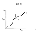
- FIG. 15 such a movement path S for the biaxial machine according to FIG. 1 is shown by way of example.
- designed as a milling head machine element 8 is guided on the movement path S.
- the drive axle 6a of FIG. 1 is responsible for the movement in the X 1 direction, while the drive axle 6b is responsible for the movement in the X 2 direction.
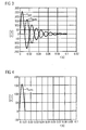
- FIG. 2 shows, by way of example, the time profile of the load actual speed n List1 (impulse response) of the drive axle 6a according to FIG. 1 after excitation with a pulse for damping D ⁇ 1.
- the vibration of the Lastistcard n List1 should now be avoided by the known method of "Input Shaping" as far as possible.
- the PT2 element is excited by another pulse, which is applied later by half the period of the oscillation period T d . Its amplitude is chosen so that the maximum, the second impulse response generated from this impulse excitation is equal to the minimum of the first.
- FIG. 3 shows the impulse response n List1 and the delayed impulse response n List1v .
- the sum impulse response of the PT2 element to both pulses is shown in the form of a summation load speed n List1s .
- the position X List1 of the machine element By integrating the summation load speed n List1s , the position X List1 of the machine element , the course of which is shown in FIG. 5, results.
- the position X List1 was nominated to a value of "1".
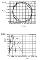
- FIG 7 is to be traversed as a trajectory S a circle.
- the actual position curves X List1 and X List2 of the respectively associated drive axes 6a and 6b are shown in FIG.
- the curve 9a shows the ideal circuit.
- the curve 10a shows the course of the circle during operation of the machine without "input shaping". Accuracy problems occur as a result of the occurring mechanical vibrations of the drive axles 6a and 6b.
- the curve 11a shows the result during operation with "input shaping" of the two drive axles 6a and 6b.
- the circle has an elliptical course. Although mechanical vibrations are no longer stimulated by "input shaping", the result is no better than conventional operation without "input shaping".
- the object of the present invention is therefore a method for guiding the movement of a movable machine element a tool or production machine with at least two To create drive axles, in which the process of "input Shaping "is developed so much that the drive axles
- the machines can also work in a geometric composite.
- This object is achieved by a method for motion control a movable machine element of a tool or production machine with at least two drive axles, wherein for each drive axle of the machine, respectively the drive axle assigned setpoint values for controlling the motion control one of the respective drive axle assigned Control can be supplied as a rule setpoints, the Setpoints of the drive axes with the lowest mechanical Natural frequency delayed in time.
- this object is achieved by a device for guiding the movement of a movable machine element of a Tool or production machine with at least two drive axles, wherein for each drive axle of the machine, respectively setpoint values assigned to the drive axis for control the movement guide generated by a controller of the machine and one of the respective drive axle associated control can be fed as a controlled setpoint, the setpoints the drive axes with the lowest mechanical natural frequency delayed by means of a retarder are.
- Machine tools e.g. single or multi-axis turning, milling, Drilling or grinding machines understood.
- To the machine tools are in the context of the present invention also Machining centers, linear and rotary transfer machines, Counted laser or Wälz- and Vertechnikmaschinen. All have in common is that a material is edited, where This processing can be performed multi-axially.
- To the Production machines are within the scope of the present invention e.g. Textile, plastic, wood, glass, ceramic or Stone processing machines counted.
- Machines of forming technology, Packaging technology, printing technology, materials handling, transport technology, Lifting tools, cranes, robots and production lines are also within the scope of the present invention to the production machines.
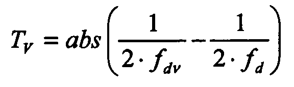
- a first advantageous embodiment of the invention is characterized in that the setpoint values of the drive axes with the non-lowest mechanical natural frequency are preferably respectively by the delay time be delayed, where f dv is the mechanical natural frequency of the respective drive axis v with the non-lowest mechanical natural frequency and f d is the drive axis with the lowest mechanical natural frequency.
- the setpoint values in Form of speed setpoints, position setpoints, acceleration setpoints or truck setpoints lie from the controller to the control setpoints usually in the form of speed, location, acceleration or jerk in front.
- the inventive method can for all types of setpoints are used.
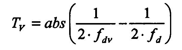
- the setpoint values of the drive axes with the lowest natural mechanical frequency are preferably respectively by the delay time are delayable , where f dv is the mechanical natural frequency of the respective drive axis v with the non-lowest mechanical natural frequency and f d is the drive axis with the lowest mechanical natural frequency.
- setpoint values in Form of speed setpoints, position setpoints, acceleration setpoints or truck setpoints.
- the device according to the invention can be used for all types of setpoint values be used.
- the retarder integral part of an extension to the retarder Control is.
- the retarder can easily in particular with numerical controls in an already existing control be integrated without any additional hardware needed for the realization of the retarder.
- the retarder 10 an integral part of a deluxe extension Regulation is.
- the retarder can easily in particular with numerical regulations in an existing regulation be integrated without any additional hardware needed for the realization of the retarder.
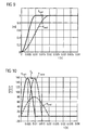
- FIG. 9 the positions X List1 and X List2 associated with the respective last actual speed n List1 and n List2 are recorded , which were determined by integration of the respectively associated load actual speed n Ligt1 and n List2 . It can be seen that the position X List1 and X List2 are constructed according to FIG. 9 with different delays. At the contour, for example at the circle according to FIG. 7, this has corresponding contour distortions.
- the basic idea of the present invention is now to provide the desired speed values which are sent by the controller 1 to the respective control and, as a result of the input shaping carried out by the control, for each drive axle as two staggered input pulse sequences (in FIG Input pulse sequence shown by way of example for the drive shaft 6a) to balance the speed setpoint values such that the contour error of the movement path S caused by the "input shaping" becomes minimal.
- this takes place in that the setpoint values of the drive axes v are delayed in time with the non-lowest mechanical natural frequency f dv .
- the index v runs from 1 to n-1, where n is the number of drive axes of the machine.
- the required delay time T v can be clearly read from FIG.
- FIG. 10 again shows the two load actual speeds n istL1 and n is L 2 from FIG. 8.
- the Lastist loftiere n is L1 , which is the drive axis with not the lowest mechanical natural frequency f d1 (drive shaft 1 has in the embodiment, a natural frequency of 50 Hz and drive shaft 2 has a natural frequency of 25 Hz) is now according to the invention delayed in time to an adaptation to to ensure the Lastisttaxiere the drive axle with the lowest mechanical natural frequency, which is the axis 6b in the embodiment, according to FIG.
- the by the time T v delayed Lastistcard n istL1 is designated in FIG 10 with n List1d.
- the amplitude of the delayed Lastistcard n List1d and Lastistsearchiere n List1 the second drive axle (drive axle with the lowest mechanical natural frequency f d ) must coincide in time.
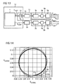
- FIG. 13 shows a device according to the invention for guiding the movement of a movable element of a tool or production machine.
- the device according to the invention for guiding movement according to FIG. 13 agrees with the commercially available device for distributing the movement according to FIG. 1, except for the presence of an additional time delay 10, both functionally and in the designation of the individual components, so that with respect to the general functioning of the Device and name of the components, to which reference is made in the description made to FIG 1 embodiments.
- the load speed setpoints n Lsoll1 of the drive axle 6a are delayed by means of a delay 10 by the delay time T v , before they are fed to the control 2a as a control setpoint.
- FIG 14 the improvement achieved by the invention the trajectory based on the already described in FIG 7 Circular motion shown.
- the curve 9b represents the ideal Circular path
- the curve 10b represents the course of the circular path in conventional operation without "input shaping”
- FIG 11b shows the course of the circular path with "Input Shaping” and Application of the method according to the invention. How to can easily recognize, the circular path 11b is almost identical with the ideal circular path 9b. Especially against the Circular path 11a with "input shaping" but without the invention Procedure was achieved a significant improvement.
- the invention was based on a biaxial in the embodiment Machine described. Of course, the invention even with a machine with three or more drive axles applicable. This also allows spatial movements by means of the method according to the invention and the invention Realize facility in very good quality.
- the mechanical natural frequency of the damped oscillation of the individual drive axes v can be determined by means of common measuring methods (eg via a spectral excitation of the drive axis and measurement of the vibrations occurring), so that the load speed setpoints of the individual drive axles v with the non-lowest mechanical natural frequency f dv by means of a respective associated delay can be delayed in time accordingly.
- speed setpoints were used in the form of speed setpoints from the controller 1 to the controller 2a and 2b according to FIG. 1 for controlling the motion control passed the machine element.
- the setpoints can also be in the form of position setpoints, acceleration setpoints or shot setpoints, i. between the controller and the individual controls of the drive axles
- the setpoints can also be in the form of position, acceleration or jerk.
- the position setpoints, acceleration setpoints or Rucksolllitis can according to the invention be delayed accordingly. So that the invention is also applicable to these types of setpoints.
- the retarder 10 integral part of an extended to the retarder 10 Control 12 can be.
- the retarder 10 can be light especially with numerical controls in an already existing Control can be integrated without additional Hardware required for the realization of the retarder becomes.
- the retarder 10 but also an integral part a to the retarder 10 extended control 13th can be.
- the retarder 10 can easily be used in particular in numerical Integrated into an already existing regulation are without any additional hardware Realization of the retarder is needed.
- the drive axles can have several natural frequencies.
- the process according to the invention can be understood to each of these natural frequencies independently by e.g. application Apply the overlay principle.
Landscapes
- Engineering & Computer Science (AREA)
- Human Computer Interaction (AREA)
- Manufacturing & Machinery (AREA)
- Physics & Mathematics (AREA)
- General Physics & Mathematics (AREA)
- Automation & Control Theory (AREA)
- Numerical Control (AREA)
Abstract
Description
- D:
- Dämpfung der Mechanik
- ω0:
- Eigenkreisfrequenz der ungedämpften Mechanik
- t :
- Zeit
- f0 =
- Eigenfrequenz der ungedämpften Mechanik.
- fd:
- Eigenfrequenz des gedämpften mechanischen Systems
- Td:
- Schwingungsdauer des gedämpften mechanischen Systems
- FIG 1
- ein Blockschaltbild einer zweiachsigen Werkzeug- oder Produktionsmaschine,
- FIG 2
- Impulsantwort eines PT2-Gliedes mit Dämpfung kleiner 1,
- FIG 3
- Impulsantworten eines PT2-Gliedes auf zwei zeitlich versetzte Eingangsimpulse,
- FIG 4
- Summenimpulsantwort des PT2-Gliedes auf zwei zeitlich versetzte Impulse,
- FIG 5
- normierter Verlauf der Lage eines Maschinenelements,
- FIG 6
- zeitdiskrete Impulse des Lagesollwertverlaufs,
- FIG 7
- Bewegungsbahnen, ideal, bei konventionellem Betrieb und mit "Input Shaping"
- FIG 8
- Verlauf der Lastdrehzahlistwerte nach Sollwertsprung,
- FIG 9
- Verlauf der Lageistwerte nach Sollwertsprung,
- FIG 10
- erfindungsgemäße zeitliche Verzögerung der Lastdrehzahlistwerte,
- FIG 11
- Verläufe der Lageistwerte beim erfindungsgemäßen Verfahren,
- FIG 12
- erfindungsgemäße zeitliche Verzögerung eines Sollwertes,
- FIG 13
- erfindungsgemäße Einrichtung zur Steuerung der Bewegungsführung,
- FIG 14
- die durch das erfindungsgemäße Verfahren resultierende Bewegungsbahn am Beispiel eines Kreises und
- FIG 15
- eine Bewegungsbahn eines Maschinenelementes.

- n:
- Anzahl der Antriebsachsen
- abs(u):
- Betrag der Funktion u
Claims (8)
- Verfahren zur Bewegungsführung eines bewegbaren Maschinenelements (8) einer Werkzeug- oder Produktionsmaschine mit mindestens zwei Antriebsachsen (6a,6b), wobei für jede Antriebsachse (6a,6b) der Maschine, jeweilig der Antriebsachse (6a,6b) zugeordnete Sollwerte (nLsoll1, nLsoll2) zur Steuerung der Bewegungsführung einer der jeweiligen Antriebsachse (6a,6b) zugeordneten Regelung (2a,2b) als Regelsollgröße zugeführt werden, wobei die Sollwerte (nLsoll1, nLsoll2) der Antriebsachsen (2a,2b) mit der nicht niedrigsten mechanischen Eigenfrequenz (fdv) zeitlich verzögert werden.
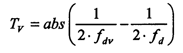
- Verfahren nach Anspruch 1, dadurch gekennzeichnet, dass die Sollwerte (nLsoll1, nLsoll2) der Antriebsachsen (6a,6b) mit der nicht niedrigsten mechanischen Eigenfrequenz fdv vorzugsweise jeweilig um die Verzögerungszeitverzögert werden, wobei fdv die mechanische Eigenfrequenz der jeweiligen Antriebsachse v mit der nicht niedrigsten mechanischen Eigenfrequenz ist und fd die Antriebsachse mit der niedrigsten mechanischen Eigenfrequenz ist.
- Verfahren nach einem der vorhergehenden Ansprüche,
dadurch gekennzeichnet, dass die Sollwerte (nLsoll1, nLsoll2) in Form von Geschwindigkeitssollwerten, Lagesollwerten, Beschleunigungssollwerten oder Rucksollwerten vorliegen. - Einrichtung zur Bewegungsführung eines bewegbaren Maschinenelements (8) einer Werkzeug- oder Produktionsmaschine mit mindestens zwei Antriebsachsen (6a,6b), wobei für jede Antriebsachse (6a,6b) der Maschine, jeweilig der Antriebsachse zugeordnete Sollwerte (nLsoll1, nLsoll2) zur Steuerung der Bewegungsführung von einer Steuerung (1) der Maschine erzeugbar und einer der jeweiligen Antriebsachse (6a,6b) zugeordneten Regelung (2a,2b) als Regelsollgröße zuführbar sind, wobei die Sollwerte (nlsoll1, nLsoll2) der Antriebsachsen (2a,2b) mit der nicht niedrigsten mechanischen Eigenfrequenz (fdv) mittels eines Verzögerers (10) zeitlich verzögerbar sind.
- Einrichtung nach Anspruch 4, dadurch gekennzeichnet, dass die Sollwerte (nLsoll1. nLsoll2) der Antriebsachsen (6a,6b) mit der nicht niedriasten mechanischen Eigenfrequenz fdv vorzugsweise jeweilig um die Verzögerungszeitverzögerbar sind, wobei fd1 die mechanische Eigenfrequenz der jeweiligen Antriebsachse v mit der nicht niedrigsten mechanischen Eigenfrequenz ist und fd die Antriebsachse mit der niedrigsten mechanischen Eigenfrequenz ist.

- Einrichtung nach Anspruch 4 oder 5, dadurch gekennzeichnet, dass die Sollwerte (nLsoll1, nLsoll2) in Form von Geschwindigkeitssollwerten, Lagesollwerten, Beschleunigungssollwerten oder Rucksollwerten vorliegen.
- Einrichtung nach Anspruch 4, 5 oder 6, dadurch gekennzeichnet, dass der Verzögerer 10 integraler Bestandteil einer um den Verzögerer 10 erweiterten Steuerung 12 ist.
- Einrichtung nach Anspruch 4, 5 oder 6, dadurch gekennzeichnet, dass der Verzögerer 10 integraler Bestandteil einer um den Verzögerer 10 erweiterten Regelung 13 ist.
Applications Claiming Priority (2)
| Application Number | Priority Date | Filing Date | Title |
|---|---|---|---|
| DE10359984A DE10359984B4 (de) | 2003-12-19 | 2003-12-19 | Verfahren und Einrichtung zur Bewegungsführung eines bewegbaren Maschinenelements einer Werkzeug- oder Produktionsmaschine |
| DE10359984 | 2003-12-19 |
Publications (2)
| Publication Number | Publication Date |
|---|---|
| EP1544699A1 true EP1544699A1 (de) | 2005-06-22 |
| EP1544699B1 EP1544699B1 (de) | 2007-08-22 |
Family
ID=34485529
Family Applications (1)
| Application Number | Title | Priority Date | Filing Date |
|---|---|---|---|
| EP04028163A Expired - Lifetime EP1544699B1 (de) | 2003-12-19 | 2004-11-26 | Verfahren und Einrichtung zur Bewegungsführung eines bewegbaren Maschinenelementes einer Werkzeug- oder Produktionsmaschine |
Country Status (3)
| Country | Link |
|---|---|
| US (1) | US7319910B2 (de) |
| EP (1) | EP1544699B1 (de) |
| DE (2) | DE10359984B4 (de) |
Cited By (1)
| Publication number | Priority date | Publication date | Assignee | Title |
|---|---|---|---|---|
| CN108919652A (zh) * | 2018-10-10 | 2018-11-30 | 北京工商大学 | 一种自适应抗扰整形控制方法与系统 |
Families Citing this family (6)
| Publication number | Priority date | Publication date | Assignee | Title |
|---|---|---|---|---|
| DE102004059966B3 (de) * | 2004-12-13 | 2006-06-22 | Siemens Ag | Verfahren und Einrichtung zur Bewegungsführung eines bewegbaren Maschinenelements einer numerisch gesteurten Maschine |
| DE102006015359B4 (de) * | 2006-04-03 | 2011-05-19 | Siemens Ag | Betriebsverfahren für eine Anlage mit einem mechanisch bewegbaren Element sowie Datenträger und Steuereinrichtung zur Realisierung eines derartigen Betriebsverfahrens |
| DE102010001781A1 (de) * | 2010-02-10 | 2011-08-11 | Siemens Aktiengesellschaft, 80333 | Verfahren zur Bewegung eines Maschinenelements einer Maschine aus der Automatisierungstechnik und Steuereinrichtung |
| DE102010001829B4 (de) * | 2010-02-11 | 2011-09-01 | Siemens Aktiengesellschaft | Verfahren zur Bewegung eines Maschinenelements einer Maschine aus der Automatisierungstechnik und Antriebssystem |
| DE102010015425A1 (de) * | 2010-04-19 | 2011-10-20 | Audi Ag | Vorrichtung zum Betreiben einer Antriebseinheit eines Kraftfahrzeugs |
| EP3183093B1 (de) | 2015-06-22 | 2020-08-05 | Electro Scientific Industries, Inc. | Mehrachsiges maschinenwerkzeug und verfahren zur steuerung davon |
Citations (1)
| Publication number | Priority date | Publication date | Assignee | Title |
|---|---|---|---|---|
| US5465035A (en) * | 1993-05-11 | 1995-11-07 | Quantum Corporation | Band limited control of a flexible structure using piecewise trigonometric input signals |
Family Cites Families (15)
| Publication number | Priority date | Publication date | Assignee | Title |
|---|---|---|---|---|
| US3699563A (en) * | 1969-11-25 | 1972-10-17 | Canadian Nat Railway Co | Wheel slip detector |
| US4031509A (en) * | 1975-06-27 | 1977-06-21 | General Electric Company | Locked axle detector for a multi-axled traction vehicle |
| US4219767A (en) * | 1979-03-29 | 1980-08-26 | Tektronix, Inc. | System and method of minimizing velocity fluctuations in a synchronous motor shaft |
| US4287461A (en) * | 1979-12-06 | 1981-09-01 | International Business Machines Corporation | Motor driving system |
| US4651070A (en) * | 1985-08-01 | 1987-03-17 | Westinghouse Electric Corp. | Transit vehicle start-up propulsion motor control apparatus and method |
| DE3866203D1 (de) * | 1987-09-28 | 1991-12-19 | Siemens Ag | Verfahren zur numerisch gesteuerten lageregelung elektromotorisch angetriebener achsen. |
| US5062064A (en) * | 1989-09-01 | 1991-10-29 | Berkeley Process Control, Inc. | Method and apparatus for measuring velocity in servo systems |
| US5638267A (en) * | 1994-06-15 | 1997-06-10 | Convolve, Inc. | Method and apparatus for minimizing unwanted dynamics in a physical system |
| ES2128091T3 (es) * | 1994-10-21 | 1999-05-01 | Siemens Ag | Control de velocidad con limitacion de sacudida. |
| US6505085B1 (en) * | 1999-03-04 | 2003-01-07 | Massachusetts Institute Of Technology | Method and apparatus for creating time-optimal commands for linear systems |
| US6023988A (en) * | 1998-08-10 | 2000-02-15 | Case Corporation | Calibration system for a power shift transmission |
| US6567711B1 (en) * | 2000-08-28 | 2003-05-20 | Brooks Automation | Observer-corrector control system for systems with unmodeled dynamics |
| DE10133612A1 (de) * | 2001-07-13 | 2003-02-06 | Prometec Gmbh | Numerische Steuerung für eine Werkzeugmaschine, sowie Verfahren zur numerischen Steuerung und Verfahren zur Überwachung einer Werkzeugmaschine |
| US6948381B1 (en) * | 2002-04-09 | 2005-09-27 | Rockwell Automation Technologies, Inc. | System and method for sensing torque on a rotating shaft |
| DE10355614B4 (de) * | 2003-11-28 | 2006-11-23 | Siemens Ag | Einrichtung und Verfahren zur Bewegungsaufteilung einer Bewegung eines Maschinenteils entlang einer Antriebsachse einer Werkzeug- oder Produktionsmaschine |
-
2003
- 2003-12-19 DE DE10359984A patent/DE10359984B4/de not_active Expired - Fee Related
-
2004
- 2004-11-26 DE DE502004004715T patent/DE502004004715D1/de not_active Expired - Lifetime
- 2004-11-26 EP EP04028163A patent/EP1544699B1/de not_active Expired - Lifetime
- 2004-12-17 US US11/016,693 patent/US7319910B2/en not_active Expired - Fee Related
Patent Citations (1)
| Publication number | Priority date | Publication date | Assignee | Title |
|---|---|---|---|---|
| US5465035A (en) * | 1993-05-11 | 1995-11-07 | Quantum Corporation | Band limited control of a flexible structure using piecewise trigonometric input signals |
Non-Patent Citations (1)
| Title |
|---|
| SINGER N C ET AL: "EXPERIMENTAL VERIFICATION OF COMMAND SHAPING METHODS FOR CONTROLLING RESIDUAL VIBRATION IN FLEXIBLE ROBOTS", PROCEEDINGS OF THE AMERICAN CONTROL CONFERENCE. SAN DIEGO, MAY 23 - 25, 1990, NEW YORK, IEEE, US, vol. VOL. 2 CONF. 9, 23 May 1990 (1990-05-23), pages 1738 - 1744, XP000170010 * |
Cited By (2)
| Publication number | Priority date | Publication date | Assignee | Title |
|---|---|---|---|---|
| CN108919652A (zh) * | 2018-10-10 | 2018-11-30 | 北京工商大学 | 一种自适应抗扰整形控制方法与系统 |
| CN108919652B (zh) * | 2018-10-10 | 2021-07-27 | 北京工商大学 | 一种自适应抗扰整形控制方法与系统 |
Also Published As
| Publication number | Publication date |
|---|---|
| DE502004004715D1 (de) | 2007-10-04 |
| US7319910B2 (en) | 2008-01-15 |
| DE10359984A1 (de) | 2005-07-21 |
| DE10359984B4 (de) | 2006-11-23 |
| US20050143847A1 (en) | 2005-06-30 |
| EP1544699B1 (de) | 2007-08-22 |
Similar Documents
| Publication | Publication Date | Title |
|---|---|---|
| EP1226476B1 (de) | Verfahren und schaltungsanordnung zur erzeugung von lagesollwerten für einen lageregelkreis einer numerisch bahngesteuerten maschine | |
| EP2174748B1 (de) | Werkzeugmaschine und Verfahren zur Dämpfung von Schwingbewegungen eines Maschinenelements einer Werkzeugmaschine | |
| DE19963414B4 (de) | Numerisch gesteuertes System und für das System zu verwendende Totgang-Kompensationsvorrichtung | |
| DE60100372T2 (de) | Steuervorrichtung für eine Maschine | |
| DE10355614B4 (de) | Einrichtung und Verfahren zur Bewegungsaufteilung einer Bewegung eines Maschinenteils entlang einer Antriebsachse einer Werkzeug- oder Produktionsmaschine | |
| EP2156252B1 (de) | Mess- oder werkzeugmaschine mit redundanten translatorisch wirksamen achsen zur kontinuierlichen bewegung an komplexen bahnkurven | |
| EP1688807B2 (de) | Verfahren zur Bewegungsaufteilung einer Relativbewegung zwischen einem Werkstück und einem Werkzeug einer Werkzeugmaschine | |
| EP0594699A1 (de) | Cnc-gesteuerte mehrachsige werkzeugträger. | |
| DE102016000265A1 (de) | Motorsteuervorrichtung mit Schwingungsunterdrückung | |
| DE69007727T2 (de) | Vorrichtung zum Bearbeiten nichtkreisförmiger Werkstücke. | |
| EP1963935B1 (de) | Ermittlungsverfahren für eine lagegeführt abzufahrende grobbahn | |
| EP1934660B1 (de) | Verfahren und einrichtung zur bewegungsführung eines bewegbaren maschinenelements einer maschine | |
| DE69910119T2 (de) | Steuerungseinheit für Maschine | |
| EP0896263B1 (de) | Verfahren und Schaltungsanordnung zur Ermittlung optimaler Reglerparameter für eine Drehzahlregelung | |
| DE102015111964A1 (de) | Servomotoren-Steuersystem, das die Bearbeitungspräzision mehrerer Achsen verbessert | |
| EP3908425B1 (de) | Vibrationsdämpfung bei einer werkzeugmaschine mit mehrfacher vibrationserfassung | |
| EP0931283B1 (de) | Verfahren und regelungsstruktur zur momentenvorsteuerung numerisch geregelter, elastischer und damit schwingungsfähiger mehrmassensysteme | |
| EP1544699B1 (de) | Verfahren und Einrichtung zur Bewegungsführung eines bewegbaren Maschinenelementes einer Werkzeug- oder Produktionsmaschine | |
| EP1118043A1 (de) | Verfahren und schaltungsanordnung zur automatischen parametrierung eines schnellen digitalen drehzahlregelkreises | |
| EP0883463B1 (de) | Verfahren und vorrichtung zur kompensation dynamischer verlagerungen an spanabhebenden werkzeugmaschinen | |
| EP1005147A2 (de) | Verfahren und Schaltungsanordnung zur Ermittlung einer optimalen Verstärkung des Integrators eines Drehzahlreglers | |
| DE19630694A1 (de) | Verfahren und Vorrichtung zur Kompensation dynamischer Verlagerungen an spanabhebenden Werkzeugmaschinen | |
| EP3955073A1 (de) | Betreiben einer wenigstens zweiachsigen werkzeugmaschine | |
| WO2007079778A1 (de) | Verfahren zur achsregelung | |
| DE102008019742A1 (de) | Verfahren zur Dämpfung von Maschinenresonanzen |
Legal Events
| Date | Code | Title | Description |
|---|---|---|---|
| PUAI | Public reference made under article 153(3) epc to a published international application that has entered the european phase |
Free format text: ORIGINAL CODE: 0009012 |
|
| AK | Designated contracting states |
Kind code of ref document: A1 Designated state(s): AT BE BG CH CY CZ DE DK EE ES FI FR GB GR HU IE IS IT LI LU MC NL PL PT RO SE SI SK TR |
|
| AX | Request for extension of the european patent |
Extension state: AL HR LT LV MK YU |
|
| 17P | Request for examination filed |
Effective date: 20050721 |
|
| AKX | Designation fees paid |
Designated state(s): DE FR GB |
|
| GRAP | Despatch of communication of intention to grant a patent |
Free format text: ORIGINAL CODE: EPIDOSNIGR1 |
|
| GRAS | Grant fee paid |
Free format text: ORIGINAL CODE: EPIDOSNIGR3 |
|
| GRAA | (expected) grant |
Free format text: ORIGINAL CODE: 0009210 |
|
| AK | Designated contracting states |
Kind code of ref document: B1 Designated state(s): DE FR GB |
|
| REG | Reference to a national code |
Ref country code: GB Ref legal event code: FG4D Free format text: NOT ENGLISH |
|
| GBT | Gb: translation of ep patent filed (gb section 77(6)(a)/1977) |
Effective date: 20070822 |
|
| REF | Corresponds to: |
Ref document number: 502004004715 Country of ref document: DE Date of ref document: 20071004 Kind code of ref document: P |
|
| ET | Fr: translation filed | ||
| PLBE | No opposition filed within time limit |
Free format text: ORIGINAL CODE: 0009261 |
|
| STAA | Information on the status of an ep patent application or granted ep patent |
Free format text: STATUS: NO OPPOSITION FILED WITHIN TIME LIMIT |
|
| 26N | No opposition filed |
Effective date: 20080526 |
|
| PGFP | Annual fee paid to national office [announced via postgrant information from national office to epo] |
Ref country code: GB Payment date: 20091112 Year of fee payment: 6 |
|
| GBPC | Gb: european patent ceased through non-payment of renewal fee |
Effective date: 20101126 |
|
| PG25 | Lapsed in a contracting state [announced via postgrant information from national office to epo] |
Ref country code: GB Free format text: LAPSE BECAUSE OF NON-PAYMENT OF DUE FEES Effective date: 20101126 |
|
| REG | Reference to a national code |
Ref country code: FR Ref legal event code: PLFP Year of fee payment: 12 |
|
| REG | Reference to a national code |
Ref country code: FR Ref legal event code: PLFP Year of fee payment: 13 |
|
| REG | Reference to a national code |
Ref country code: FR Ref legal event code: PLFP Year of fee payment: 14 |
|
| PGFP | Annual fee paid to national office [announced via postgrant information from national office to epo] |
Ref country code: FR Payment date: 20181120 Year of fee payment: 15 |
|
| PGFP | Annual fee paid to national office [announced via postgrant information from national office to epo] |
Ref country code: DE Payment date: 20190118 Year of fee payment: 15 |
|
| REG | Reference to a national code |
Ref country code: DE Ref legal event code: R119 Ref document number: 502004004715 Country of ref document: DE |
|
| PG25 | Lapsed in a contracting state [announced via postgrant information from national office to epo] |
Ref country code: DE Free format text: LAPSE BECAUSE OF NON-PAYMENT OF DUE FEES Effective date: 20200603 Ref country code: FR Free format text: LAPSE BECAUSE OF NON-PAYMENT OF DUE FEES Effective date: 20191130 |