EP1544695B1 - Elektronische uhr - Google Patents
Elektronische uhr Download PDFInfo
- Publication number
- EP1544695B1 EP1544695B1 EP03798381A EP03798381A EP1544695B1 EP 1544695 B1 EP1544695 B1 EP 1544695B1 EP 03798381 A EP03798381 A EP 03798381A EP 03798381 A EP03798381 A EP 03798381A EP 1544695 B1 EP1544695 B1 EP 1544695B1
- Authority
- EP
- European Patent Office
- Prior art keywords
- power generation
- power
- power generating
- voltage
- generation detecting
- Prior art date
- Legal status (The legal status is an assumption and is not a legal conclusion. Google has not performed a legal analysis and makes no representation as to the accuracy of the status listed.)
- Expired - Lifetime
Links
- 238000001514 detection method Methods 0.000 claims abstract description 11
- 238000010248 power generation Methods 0.000 claims description 63
- 238000009825 accumulation Methods 0.000 abstract 8
- 239000003990 capacitor Substances 0.000 description 11
- 238000010276 construction Methods 0.000 description 6
- 238000010586 diagram Methods 0.000 description 5
- 238000000034 method Methods 0.000 description 5
- 238000005516 engineering process Methods 0.000 description 4
- 238000004519 manufacturing process Methods 0.000 description 3
- 238000004804 winding Methods 0.000 description 2
- 238000007796 conventional method Methods 0.000 description 1
- 230000007547 defect Effects 0.000 description 1
- 230000001747 exhibiting effect Effects 0.000 description 1
- 238000005259 measurement Methods 0.000 description 1
- 230000000007 visual effect Effects 0.000 description 1
Images
Classifications
-
- G—PHYSICS
- G04—HOROLOGY
- G04C—ELECTROMECHANICAL CLOCKS OR WATCHES
- G04C10/00—Arrangements of electric power supplies in time pieces
-
- G—PHYSICS
- G04—HOROLOGY
- G04C—ELECTROMECHANICAL CLOCKS OR WATCHES
- G04C10/00—Arrangements of electric power supplies in time pieces
- G04C10/04—Arrangements of electric power supplies in time pieces with means for indicating the condition of the power supply
Definitions
- the invention relates to an electronic timepiece having a power generating unit and being driven by power generated by the power generating unit, and, more specifically, it relates to a technology for detecting a power generation state of the power -generating unit and informing the detection result.
- an electronic timepiece including a power generating unit, whether the power generating unit is normally operating or not, whether a path for feeding power generated by the power generating unit to the electronic timepiece is securely connected or not, and so on must be checked in production steps in order to secure basic operations as the power-generating timepiece.
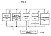
- a state is attained that an external operating member 56 such as the winding knob is pull out
- the power generation state of a power generating unit 50 is detected by a power generation detecting unit 52.
- microcurrent is output from a micropulse generating unit 57 to a motor coil (not shown) through a motor driver circuit (not shown).
- a checker can check that the power generating unit 50 is generating power by detecting a change in magnetic field occurring in a motor coil upon output of microcurrent through the visual check of movement of an external device such as a second hand attached to a train (both of which are not shown) connecting to a motor or through a tester.
- the power generating unit 50 and a storage unit 54 are connected directly or through an anti-backflow diode 64.
- the voltage occurring across the storage unit 54 exhibits a substantially constant value in accordance with a voltage value output from the storage unit 54 irrespective of the presence of the power generation of the power generating unit 50.
- the voltage of the power generating unit 50 is zero (0).
- the voltage which is a sum of an amount of a drop in voltage caused when a current value caused when the power generating unit 50 generates power is fed to the anti-backflow diode 64 and a voltage value output from the storage unit 54, occurs across the power generating unit 50.
- voltage occurring across the power generating unit 50 depends on voltage output from the storage unit 54 and is originally a different value from that of the power generation voltage that the power generating unit 50 generates.
- the presence of the connection of an electronic timepiece including the power generating unit 50 and storage unit 54 and whether power having a value equivalent to that of voltage output by the storage unit is generated or not could be checked, but whether the power generating unit 50 is generating the originally expected power generation voltage or not could not be checked.
- the voltage generated by the power generating unit 50 In order to charge electric energy generated by the power generating unit 50 into the storage unit 54, the voltage generated by the power generating unit 50 must be larger than the voltage output from the storage unit 54.
- the storage unit 54 generally tends to have a potential increasing in accordance with an amount of stored power. Therefore, in order to have the storage unit 54 fully charged, the power generation voltage of the power generating unit 50 must be larger than the voltage output when the storage unit 54 is fully charged.
- an operation of detecting power generation must be performed by detaching the storage unit 54 or by fully charging the storage unit 54.
- the examinations under those states increase the number of man-hours and/or increase the manufacturing costs.
- the conventional technology has problems that sufficient examinations cannot be performed or that a large amount of efforts is required for performing sufficient examinations.
- It is an object of the invention is to provide an electronic timepiece, which can overcome the above-described defects and can securely check operations of a power generating unit irrespective of the state of a power storage unit.
- Document D1 discloses an electronic watch with generating function, including power generating means, storage means detecting means and deciding means for detection and deciding, whether the generating means is in a power generating state, wherein the power generation state can be detected based on a difference in an electric potential between both terminals of the generating means.
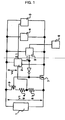
- Fig. 1 is a partial block diagram of an electronic timepiece indicating a first example of the invention.
- Fig. 1 includes a power generating unit 1, a power generation detecting unit 2, a control circuit 3, a storage unit 4, an informing unit 5, an external operating member 6, an n-channel transistor (electronic switch) 7, a first resistor 8a, a second resistor 8b, and a p-channel transistor (second electronic switch unit) 9.
- parts relating to a timepiece among construction elements relating to an electronic timepiece such as an oscillator circuit, frequency divider circuit, motor driver circuit and motor in a needle-driven electronic timepiece, for example, are omitted. These components of the electronic timepiece operate by using power from the storage unit 4 according to this embodiment.
- the power generation detecting unit 2 compares the detection voltage Vd and predefined reference voltage Vr, and, if Vd>Vr, turns a power generation detecting signal 21 to H.
- the informing unit 5 performs an operation for informing that the power generating unit 1 is at the power generation state to the outside.
- the power generation voltage V1 exhibits a value equal to or larger than an maximum voltage value Vmax (such as a voltage value upon fully charged) that the storage unit 4 can output, the fact that the power generating unit 1 is operating normally can be determined.
- Vmax such as a voltage value upon fully charged
- the value resulting from the division of the voltage value Vmax by the first resistor 8a and second resistor 8b may be defined as a reference signal Vr.
- n-channel transistor 7 and p-channel transistor 9 in response to the operating member 6 can be selected as required.
- a form suitable for a user can be freely selected such as performing a power generation detecting operation only for a predetermined period of time after the external operating member 6 is operated.
- the control unit 3 and power generation detecting unit 2 are driven by voltage supplied from the storage unit 4, the power generation voltage V1 generated by the power generating unit 1 is divided by the resistor 8a and resistor 8b in order to detect voltage equal to or larger than voltage output from the storage unit 4.
- the power generation detecting unit 2 and control unit 3 operate at voltage (V4, for example) output by the storage unit 4.
- the power generation detecting unit 2 that measures V1 operates at voltage V4 higher than V1 and can therefore measure V1 directly.
- V1>V4 highly possible in the invention having the power generating unit 1 and the storage unit 4 separately
- the power generation detecting unit 2 that is driven by V4 cannot directly measure V1 that is higher voltage than V4
- V1 is resistance-divided by 8a and 8b such that voltage that is always measurable even when V1>V4 (that is, Vd ⁇ V4) can be measured.
- the detecting method of the power generation detecting unit is not limited to the present method.
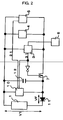
- FIG. 2 is a block diagram showing a partial construction of an electronic timepiece of the second embodiment and includes a voltage detecting unit 10 that is a power generation detecting unit, a diode 11, and a capacitor (first storage unit) 12.
- the voltage detecting unit 10 goes into action. Furthermore, the n-channel transistor 7 is turned off since the gate is turned to L through the inverter 32. When the capacitor 12 is detached from the storage unit 4 since the n-channel transistor 7 is turned off, current generated in the power generating unit 1 is fed into the capacitor 12 through the diode 11. Since the capacitor 12 has a lower capacitance than that of the storage unit 4, potentials thereacross rise in a shorter period of time. Thus, the voltage value is a value resulting from the subtraction of a voltage drop VF in the diode 11 from the power generation voltage V1 of the power generating unit 1.
- the voltage detecting unit 10 turns a power generation detecting signal 21 to H when voltage input thereto is equal to or larger than predefined voltage.
- the informing unit 5 performs an operation for informing that the power generating unit 1 is at the power generation state to the outside when the power generation detecting signal 21 is turned to H.
- the voltage detecting unit 10 used here is connected with the storage unit 4 in parallel when the n-channel transistor 7 is ON, the voltage detecting unit 10 can be also used for checking a storage state of the storage unit 4 such as whether voltage exceeds the rated voltage of the storage unit 4 or not.
- the capacitor 12 is used for operating the voltage detecting unit 10 with stability when the storage unit 4 is detached therefrom, and the diode 11 plays a role in peak holding of power generation voltage from the power generating unit 1.
- both of the capacitor 12 and diode 11 are components for performing operations of this embodiment with stability.
- the voltage detecting unit 10 When a small amount of power is generated by the power generating unit 1, for example, the voltage detecting unit 10 is cut off from power supply and is disabled without the capacitor 12 and diode 11.
- the capacitor 12 and diode 11 are connected thereto as shown in Fig. 2 , the capacitor 12 is charged to the substantially same potential as that of the storage unit 4 immediately before the n-channel transistor 7 is turned off.
- the voltage detecting unit 10 can operate for a while with charges stored in the capacitor 12, and stable detection of power generation can be therefore performed irrespective of the presence of power generation.
- the first resistor 8a, second resistor 8b and p-channel transistor 9 shown in the first example are not described and are omitted in the second example since a potential equal to or larger than power supply voltage of the power generation detecting unit 10 does not have to be detected because the power supply potential of the voltage detecting unit 10 varies in accordance with the potential output from the power generating unit 1 in the second embodiment.
- the voltage detecting unit 10 is driven by voltage (V1+VF) of the capacitor 12 to be detected thereby in the second example having the construction in Fig. 2 , the detection can be performed without resistance division.
- an electronic timepiece that is operated by electric energy generated by a power generating unit according to the invention can check an operation of the power generating unit with stability and simply, which can contribute to enhancement of the productivity.
Landscapes
- Engineering & Computer Science (AREA)
- Power Engineering (AREA)
- Physics & Mathematics (AREA)
- General Physics & Mathematics (AREA)
- Electromechanical Clocks (AREA)
- Electric Clocks (AREA)
Claims (4)
- Elektronische Uhr, die mit von einer Energie erzeugenden Einrichtung (1) erzeugter elektrischer Energie angetrieben ist, wobei die elektronische Uhr eine über einen elektronischen Schalter (7) zu der Energie erzeugenden Einrichtung (1) parallel geschaltete Speichereinrichtung (4), eine Steuereinrichtung (3), die dazu eingerichtet ist, um den elektronischen Schalter (7) zu steuern, eine Energieerzeugungs-Erfassungseinrichtung (2), die dazu eingerichtet ist, um einen Energieerzeugungszustand der Energie erzeugenden Einrichtung (1) zu erfassen, eine Mitteilungseinrichtung (5), die dazu eingerichtet ist, um ein Erfassungsergebnis der Energieerzeugungs-Erfassungseinrichtung (2) nach außen mitzuteilen, und ein externes Bedienelement (6) aufweist, wobei das externe Bedienelement (6) dazu eingerichtet ist, um die Energieerzeugungs-Erfassungseinrichtung (2) zu aktivieren, wobei ein Energieerzeugungs-Erfassungsbetrieb unter einer Bedingung durchgeführt wird, dass der elektronische Schalter (7) durch die Steuereinrichtung (3) ausgeschaltet ist, und wobei das durch die Energieerzeugungs-Erfassungseinrichtung erhaltene Ergebnis durch die Mitteilungseinrichtung (5) nach außen mitgeteilt wird; wobei die Uhr dadurch gekennzeichnet ist, dass
ein erster Widerstand (8a) und ein zweiter Widerstand (8b) und eine zweite elektronische Schalteinrichtung (9), die in Serie verbunden sind, zu der Energie erzeugenden Einrichtung (1) parallel geschaltet sind, wobei die zweite elektronische Schalteinrichtung (9) dazu eingerichtet ist, um zeitgleich zu der Aktivierung der Energieerzeugungs-Erfassungseinrichtung (2) durch das externe Bedienelement (6) eingeschaltet zu werden, und
wobei der Eingang der Energieerzeugungs-Erfassungseinrichtung (2) an den Verbindungspunkt zwischen dem ersten Widerstand (8a) und dem zweiten Widerstand (8b) angeschlossen ist. - Elektronische Uhr, die mit von einer Energie erzeugenden Einrichtung (1) erzeugter elektrischer Energie angetrieben ist, wobei die elektronische Uhr dadurch gekennzeichnet ist, dass sie eine über einen elektronischen Schalter (7) zu der Energie erzeugenden Einrichtung (1) parallel geschaltete erste Speichereinrichtung (12), eine Steuereinrichtung (3), die dazu eingerichtet ist, um den elektronischen Schalter (7) zu steuern, eine Energieerzeugungs-Erfassungseinrichtung (10), die dazu eingerichtet ist, um einen Energieerzeugungszustand der Energie erzeugenden Einrichtung (1) zu erfassen, eine Mitteilungseinrichtung (5), die dazu eingerichtet ist, um ein Erfassungsergebnis der Energieerzeugungs-Erfassungseinrichtung (10) nach außen mitzuteilen, und ein externes Bedienelement (6) aufweist, wobei die Energieerzeugungs-Erfassungseinrichtung (10) dazu eingerichtet ist, um durch das externe Bedienelement (6) aktiviert zu sein, wobei ein Energieerzeugungs-Erfassungsbetrieb unter einer Bedingung durchgeführt wird, dass der elektronische Schalter (7) durch die Steuereinrichtung (3) ausgeschaltet ist, und wobei das durch die Energieerzeugungs-Erfassungseinrichtung erhaltene Ergebnis durch die Mitteilungseinrichtung (5) nach außen mitgeteilt wird.
- Elektronische Uhr nach Anspruch 2, dadurch gekennzeichnet, dass die erste Speichereinrichtung (12) eine geringere Menge gespeicherter Energie aufweist, als die zweite Speichereinrichtung (4).
- Elektronische Uhr nach Anspruch 2 oder 3, dadurch gekennzeichnet, dass die Energieerzeugungs-Erfassungseinrichtung (10) einen Energieerzeugungszustand der Energie erzeugenden Einrichtung (1) durch Erfassung einer Spannung der ersten Speichereinrichtung (12) erfasst.
Applications Claiming Priority (3)
| Application Number | Priority Date | Filing Date | Title |
|---|---|---|---|
| JP2002280948 | 2002-09-26 | ||
| JP2002280948A JP2004117165A (ja) | 2002-09-26 | 2002-09-26 | 電子時計 |
| PCT/JP2003/011072 WO2004029734A1 (ja) | 2002-09-26 | 2003-08-29 | 電子時計 |
Publications (3)
| Publication Number | Publication Date |
|---|---|
| EP1544695A1 EP1544695A1 (de) | 2005-06-22 |
| EP1544695A4 EP1544695A4 (de) | 2011-03-23 |
| EP1544695B1 true EP1544695B1 (de) | 2011-12-28 |
Family
ID=32040499
Family Applications (1)
| Application Number | Title | Priority Date | Filing Date |
|---|---|---|---|
| EP03798381A Expired - Lifetime EP1544695B1 (de) | 2002-09-26 | 2003-08-29 | Elektronische uhr |
Country Status (5)
| Country | Link |
|---|---|
| US (1) | US7009914B2 (de) |
| EP (1) | EP1544695B1 (de) |
| JP (1) | JP2004117165A (de) |
| CN (1) | CN100416432C (de) |
| WO (1) | WO2004029734A1 (de) |
Family Cites Families (9)
| Publication number | Priority date | Publication date | Assignee | Title |
|---|---|---|---|---|
| CN1206476A (zh) * | 1996-10-31 | 1999-01-27 | 时至准钟表股份有限公司 | 电子表 |
| DE19700108B4 (de) * | 1997-01-03 | 2005-12-22 | Citizen Watch Co., Ltd. | Elektronische Uhr und Ladeverfahren derselben |
| JP3963554B2 (ja) * | 1997-06-17 | 2007-08-22 | セイコーエプソン株式会社 | 電子機器、時計および電子機器の消費電力制御方法 |
| US6301198B1 (en) * | 1997-12-11 | 2001-10-09 | Citizen Watch Co., Ltd. | Electronic timepiece |
| EP1026559B1 (de) * | 1998-08-31 | 2010-11-24 | Citizen Holdings Co., Ltd. | Elektronische uhr mit generatorfunktion |
| CN1189802C (zh) * | 1998-10-22 | 2005-02-16 | 时至准钟表股份有限公司 | 电子表 |
| EP1096640A3 (de) * | 1999-10-25 | 2002-11-27 | Seiko Epson Corporation | Wechselspannungsdetektionsschaltung und -verfahren, Ladeschaltung und -verfahren, Zerhackerschaltung und -verfahren, Zerhackerladeschaltung und -verfahren, elektronische Vorrichtung, und Uhr |
| HK1044597B (en) | 2000-09-13 | 2011-10-07 | Citizen Watch Co., Ltd. | Electronic timepiece |
| JP2002202388A (ja) * | 2000-12-28 | 2002-07-19 | Citizen Watch Co Ltd | 充電式電子時計及びその制御方法 |
-
2002
- 2002-09-26 JP JP2002280948A patent/JP2004117165A/ja active Pending
-
2003
- 2003-08-29 WO PCT/JP2003/011072 patent/WO2004029734A1/ja not_active Ceased
- 2003-08-29 US US10/525,988 patent/US7009914B2/en not_active Expired - Fee Related
- 2003-08-29 CN CNB038222027A patent/CN100416432C/zh not_active Expired - Fee Related
- 2003-08-29 EP EP03798381A patent/EP1544695B1/de not_active Expired - Lifetime
Also Published As
| Publication number | Publication date |
|---|---|
| JP2004117165A (ja) | 2004-04-15 |
| EP1544695A1 (de) | 2005-06-22 |
| CN1682162A (zh) | 2005-10-12 |
| CN100416432C (zh) | 2008-09-03 |
| WO2004029734A1 (ja) | 2004-04-08 |
| US7009914B2 (en) | 2006-03-07 |
| EP1544695A4 (de) | 2011-03-23 |
| HK1082553A1 (zh) | 2006-06-09 |
| US20050249047A1 (en) | 2005-11-10 |
Similar Documents
| Publication | Publication Date | Title |
|---|---|---|
| KR100884842B1 (ko) | 충전 제어용 반도체 집적 회로, 그 충전 제어용 반도체집적 회로를 사용한 충전 장치 및 2차 전지 접속 검출 방법 | |
| KR100884841B1 (ko) | 충전 제어용 반도체 집적 회로, 그 충전 제어용 반도체집적 회로를 사용한 충전 장치 및 2차 전지 접속 검출 방법 | |
| JP5225559B2 (ja) | 電池パックの異常判定方法および電池パック | |
| CN101141077B (zh) | 电池控制装置和电池控制方法 | |
| EP0194136B1 (de) | Elektronische Uhr mit Sonnenzelle | |
| EP1043824A2 (de) | Batterieladesteuerungsschaltung, Batterieladeeinrichtung und Batterieladesteuerungsverfahren | |
| US5740132A (en) | Electronic timepiece and method of charging the same | |
| EP2073339A2 (de) | Tragbares Gerät und Batteriepack für dieses Gerät | |
| CN101483356A (zh) | 输电控制装置、无触点电力传输系统、输电装置、电子设备以及波形监控电路 | |
| WO2000041041A1 (en) | Electronic apparatus and method of controlling electronic apparatus | |
| JP6696221B2 (ja) | 制御装置、受電装置、電子機器及び電力伝送システム | |
| US20120056480A1 (en) | Control device, electronic apparatus, timepiece device, and control method | |
| JPH0611197B2 (ja) | ステツピング・モ−タの制御装置 | |
| JP5338552B2 (ja) | 電池パックおよび電動工具 | |
| WO2000059091A1 (fr) | Equipement electronique et son procede de commande | |
| EP1544695B1 (de) | Elektronische uhr | |
| US5229706A (en) | Electronic equipment having automatic power-off function | |
| EP1081823B1 (de) | Vorrichtung und Verfahren zur Leckstrom- und Batterieselbstentladungskompenzation | |
| JP5312491B2 (ja) | 電圧表示方法、電圧表示装置及びパック電池 | |
| JP4294966B2 (ja) | 電子時計、二次電池の蓄電状態表示方法、二次電池の蓄電状態表示プログラムおよび情報処理端末装置 | |
| JP3525897B2 (ja) | 電子機器および電子機器の制御方法 | |
| US6963194B2 (en) | Analog signal measuring device and method | |
| EP1030331B1 (de) | Durch einen schalter gesteuerter zustandsdetektor und elektronische einheit | |
| US8441253B2 (en) | Measuring apparatus having charge control circuit | |
| JP2016201934A (ja) | 電源装置の劣化検知装置および劣化検知方法 |
Legal Events
| Date | Code | Title | Description |
|---|---|---|---|
| PUAI | Public reference made under article 153(3) epc to a published international application that has entered the european phase |
Free format text: ORIGINAL CODE: 0009012 |
|
| 17P | Request for examination filed |
Effective date: 20050224 |
|
| AK | Designated contracting states |
Kind code of ref document: A1 Designated state(s): AT BE BG CH CY CZ DE DK EE ES FI FR GB GR HU IE IT LI LU MC NL PT RO SE SI SK TR |
|
| AX | Request for extension of the european patent |
Extension state: AL LT LV MK |
|
| DAX | Request for extension of the european patent (deleted) | ||
| RBV | Designated contracting states (corrected) |
Designated state(s): DE IT |
|
| RAP1 | Party data changed (applicant data changed or rights of an application transferred) |
Owner name: CITIZEN HOLDINGS CO., LTD. |
|
| A4 | Supplementary search report drawn up and despatched |
Effective date: 20110223 |
|
| REG | Reference to a national code |
Ref country code: DE Ref legal event code: R079 Ref document number: 60339570 Country of ref document: DE Free format text: PREVIOUS MAIN CLASS: G04G0001000000 Ipc: G04C0010000000 |
|
| GRAP | Despatch of communication of intention to grant a patent |
Free format text: ORIGINAL CODE: EPIDOSNIGR1 |
|
| RIC1 | Information provided on ipc code assigned before grant |
Ipc: G04C 10/00 20060101AFI20110624BHEP Ipc: G04C 10/04 20060101ALI20110624BHEP |
|
| GRAS | Grant fee paid |
Free format text: ORIGINAL CODE: EPIDOSNIGR3 |
|
| GRAA | (expected) grant |
Free format text: ORIGINAL CODE: 0009210 |
|
| AK | Designated contracting states |
Kind code of ref document: B1 Designated state(s): DE IT |
|
| REG | Reference to a national code |
Ref country code: DE Ref legal event code: R081 Ref document number: 60339570 Country of ref document: DE Owner name: CITIZEN WATCH CO., LTD., NISHITOKYO-SHI, JP Free format text: FORMER OWNER: CITIZEN WATCH CO., LTD., NISHITOKYO, TOKIO/TOKYO, JP |
|
| REG | Reference to a national code |
Ref country code: DE Ref legal event code: R096 Ref document number: 60339570 Country of ref document: DE Effective date: 20120322 |
|
| PLBE | No opposition filed within time limit |
Free format text: ORIGINAL CODE: 0009261 |
|
| STAA | Information on the status of an ep patent application or granted ep patent |
Free format text: STATUS: NO OPPOSITION FILED WITHIN TIME LIMIT |
|
| 26N | No opposition filed |
Effective date: 20121001 |
|
| REG | Reference to a national code |
Ref country code: DE Ref legal event code: R097 Ref document number: 60339570 Country of ref document: DE Effective date: 20121001 |
|
| PGFP | Annual fee paid to national office [announced via postgrant information from national office to epo] |
Ref country code: DE Payment date: 20160823 Year of fee payment: 14 Ref country code: IT Payment date: 20160822 Year of fee payment: 14 |
|
| REG | Reference to a national code |
Ref country code: DE Ref legal event code: R082 Ref document number: 60339570 Country of ref document: DE Representative=s name: TBK, DE Ref country code: DE Ref legal event code: R081 Ref document number: 60339570 Country of ref document: DE Owner name: CITIZEN WATCH CO., LTD., NISHITOKYO-SHI, JP Free format text: FORMER OWNER: CITIZEN HOLDINGS CO., LTD., TOKYO, JP |
|
| REG | Reference to a national code |
Ref country code: DE Ref legal event code: R119 Ref document number: 60339570 Country of ref document: DE |
|
| PG25 | Lapsed in a contracting state [announced via postgrant information from national office to epo] |
Ref country code: DE Free format text: LAPSE BECAUSE OF NON-PAYMENT OF DUE FEES Effective date: 20180301 |
|
| PG25 | Lapsed in a contracting state [announced via postgrant information from national office to epo] |
Ref country code: IT Free format text: LAPSE BECAUSE OF NON-PAYMENT OF DUE FEES Effective date: 20170829 |