EP1544669A1 - Dispositif de régéneration d'un signal optique, utilisation d'un tel dispositif et installation comportant un tel dispositif - Google Patents
Dispositif de régéneration d'un signal optique, utilisation d'un tel dispositif et installation comportant un tel dispositif Download PDFInfo
- Publication number
- EP1544669A1 EP1544669A1 EP04293003A EP04293003A EP1544669A1 EP 1544669 A1 EP1544669 A1 EP 1544669A1 EP 04293003 A EP04293003 A EP 04293003A EP 04293003 A EP04293003 A EP 04293003A EP 1544669 A1 EP1544669 A1 EP 1544669A1
- Authority
- EP
- European Patent Office
- Prior art keywords
- optical
- signal
- amplitude
- modulation
- phase
- Prior art date
- Legal status (The legal status is an assumption and is not a legal conclusion. Google has not performed a legal analysis and makes no representation as to the accuracy of the status listed.)
- Granted
Links
- 230000003287 optical effect Effects 0.000 title claims abstract description 89
- 230000008929 regeneration Effects 0.000 claims abstract description 60
- 238000011069 regeneration method Methods 0.000 claims abstract description 60
- 230000005540 biological transmission Effects 0.000 claims abstract description 4
- 239000006096 absorbing agent Substances 0.000 claims description 12
- 230000001172 regenerating effect Effects 0.000 claims description 12
- 230000001629 suppression Effects 0.000 claims description 6
- 230000002441 reversible effect Effects 0.000 claims description 4
- 238000009434 installation Methods 0.000 claims description 3
- 230000001902 propagating effect Effects 0.000 claims description 2
- 239000013307 optical fiber Substances 0.000 abstract description 8
- 230000010363 phase shift Effects 0.000 abstract 2
- 238000006243 chemical reaction Methods 0.000 description 4
- 238000010586 diagram Methods 0.000 description 4
- 230000014509 gene expression Effects 0.000 description 4
- 239000002250 absorbent Substances 0.000 description 1
- 230000002745 absorbent Effects 0.000 description 1
- 230000003111 delayed effect Effects 0.000 description 1
- 230000001939 inductive effect Effects 0.000 description 1
- 238000000034 method Methods 0.000 description 1
- 238000012986 modification Methods 0.000 description 1
- 230000004048 modification Effects 0.000 description 1
- 230000000737 periodic effect Effects 0.000 description 1
- 230000000717 retained effect Effects 0.000 description 1
Images


Classifications
-
- H—ELECTRICITY
- H04—ELECTRIC COMMUNICATION TECHNIQUE
- H04B—TRANSMISSION
- H04B10/00—Transmission systems employing electromagnetic waves other than radio-waves, e.g. infrared, visible or ultraviolet light, or employing corpuscular radiation, e.g. quantum communication
-
- H—ELECTRICITY
- H04—ELECTRIC COMMUNICATION TECHNIQUE
- H04B—TRANSMISSION
- H04B10/00—Transmission systems employing electromagnetic waves other than radio-waves, e.g. infrared, visible or ultraviolet light, or employing corpuscular radiation, e.g. quantum communication
- H04B10/29—Repeaters
-
- H—ELECTRICITY
- H04—ELECTRIC COMMUNICATION TECHNIQUE
- H04B—TRANSMISSION
- H04B10/00—Transmission systems employing electromagnetic waves other than radio-waves, e.g. infrared, visible or ultraviolet light, or employing corpuscular radiation, e.g. quantum communication
- H04B10/50—Transmitters
-
- H—ELECTRICITY
- H04—ELECTRIC COMMUNICATION TECHNIQUE
- H04B—TRANSMISSION
- H04B10/00—Transmission systems employing electromagnetic waves other than radio-waves, e.g. infrared, visible or ultraviolet light, or employing corpuscular radiation, e.g. quantum communication
- H04B10/60—Receivers
Definitions
- the present invention relates to a device for regenerating a signal optical, a use of such a device and an installation comprising such a device.
- the invention relates to a device for regenerating a optical signal carrying information coded by phase modulation of this signal.
- a signal When a signal is transmitted in an optical fiber, it undergoes a certain number of distortions, for example, distortions of amplitude, frequency or phase. In order to recover a signal as similar as possible to the transmitted signal, it is then necessary to pass the optical signal in a regeneration device.
- a certain number of distortions for example, distortions of amplitude, frequency or phase.
- Regeneration devices are already known in the state of the art. of an optical signal carrying information coded by amplitude modulation of this signal using saturable absorbers for example.
- phase and in particular modulations of the DPSK ("Differential Phase" Shift Keying ").
- DPSK Different Phase Shift Keying
- the information is coded in the phase of signals: for example a bit “1 is encoded by a phase inversion of the carrier signal and a bit "0" by no phase change.
- the object of the invention is to remedy this drawback by proposing a regeneration device for a signal enabling the regeneration of the carrier signals information coded by modulation of their phase.
- the regeneration device therefore makes it possible to regenerate simply the phase of signals carrying information coded in modulation of phase by using existing signal regeneration devices carrying a encoded information in amplitude modulation.
- the invention also relates to an optical transmission installation comprising means for propagating optical signals, characterized in that comprises a regeneration device according to the invention previously defined, inserted in the propagation means.
- FIG. 1 An optical fiber designated by the general reference 10 is shown in FIG. 1. This optical fiber is used to transmit an optical signal S carrying a coded information by phase modulation of this signal.
- the phase modulation used is chosen for example from the known modulations RZ-DPSK and NRZ-DPSK.
- the information carried by the optical signal S is a binary information.
- the bits are spaced two by two of a duration T b that is called "bit time”.
- the signal S ( t ) is obtained by modulating the phase of a periodic carrier signal P ( t ) of period T p .
- the carrier signal is chosen such that T b is a multiple of T p .
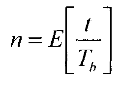
- ⁇ ( n ) be the phase of the signal corresponding to the nth bit transmitted between instants nT b and ( n +1) T b .
- the regeneration device 12 comprises a first optical modulation converter 14 for converting the signal S e carrying the information coded by phase modulation into two signals S '/ 1 and S ' / 2 carrying said information coded by amplitude modulation.
- the optical signals regenerated in the amplitude optical regeneration module 16 then pass into a second modulation optical converter 18 intended to convert the signals carrying the coded information by amplitude modulation into a signal S S carrying the optical signal.
- information coded by phase modulation The signal S S thus carries the same information coded by phase modulation as the signal S e but has meanwhile been regenerated by the optical amplitude regeneration module 16.
- the signal S e to be regenerated is split into two signals. We then speak of the two arms of the regeneration device 12 to talk about the two paths taken by the signals.
- the signals transmitted on the first arm (the upper arm in FIG. 1) comprise the index 1
- the signals transmitted on the second arm (the lower arm) comprise the index 2.
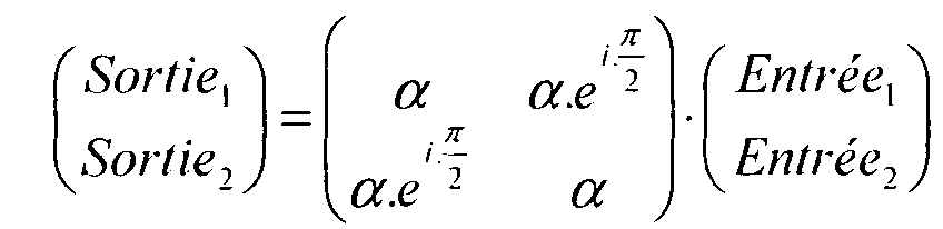
- Each optical modulation converter 14, 18 is a demodulator DPSK realized by means of two couplers 3dB 20, 22 for the module 14, and 26, 28 for the module 18, and a delay element, respectively 24 and 30, interposed between the two couplers of the first arm.
- the first coupler 3dB 20 of the optical modulation converter 14 has as its sole input signal the signal S e which enters through the input 1.
- the input 2 is connected to ground.
- S 1 The signal obtained at the output 1 of the coupler 3dB 20
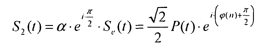
- S 2 the signal obtained at the output 2 of the coupler 3dB 20
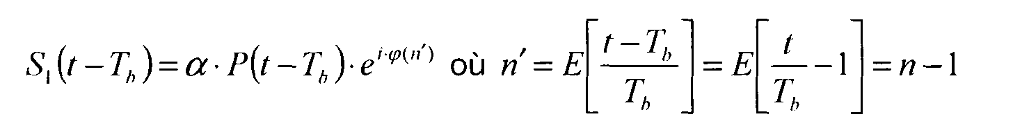
- the delay element 24, arranged on the first arm of the optical modulation converter 14, between the two couplers 3dB 20, 22, is intended to delay the signal S 1 by a bit T b before it enters in the second coupler 3dB 22.
- the delayed signal is then written:
- the signal S 2 obtained on the second arm at the output of the first coupler 3dB 20 directly enters the second coupler 3dB 22 by its second input.
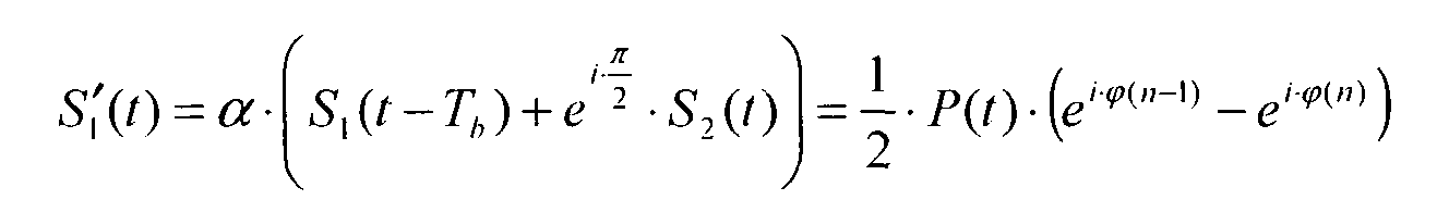
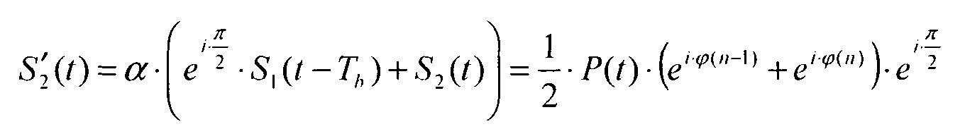
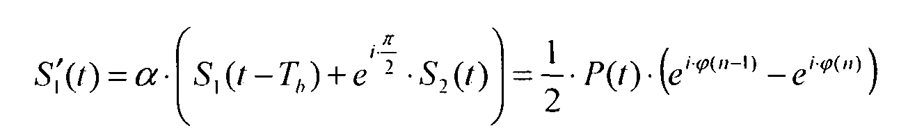
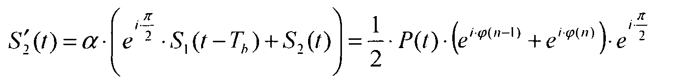
- the modulation used to code the information on the carrier signal S e is a two-state differential phase modulation.
- the two states chosen for the phase ⁇ are 0 and ⁇ .
- Two successive bits are therefore encoded by signals whose phases are either equal or opposite.
- the optical amplitude regeneration module 16 of the regeneration device 12 makes it possible to regenerate these two signals S ' 1 and S' 2 .
- This module comprises means 17 for removing noise.
- the noise suppression means 17 used are, for example, saturable absorbers which suppress the noise of the two signals S ' 1 and S ' / 2. Any other device making it possible to regenerate a signal carrying an information coded in amplitude. can also be used.
- the signal S '"/ 1 corresponding to the signal S" 1 after passing through the delay element 30 is then: S " 1 ( t ) - - 2 2 ⁇ P ( t ) ⁇ e i ⁇ ⁇ ( not -1)
- S '"/ 2 is the signal obtained at the output of the second arm of the first 3dB coupler 26 of the second modulation optical converter 18:
- the signal S S corresponds, with the sign, to the signal S e offset by a bit time.
- This regeneration device has the advantage of only include passive elements.
- a second embodiment shown in FIG. 2 uses the property of reversibility of 3dB couplers.
- optical modulation converters 14 and 18 previously described are symmetrical devices using components reversible, these optical modulation converters are also reversible. We then obtain the same results, whatever the direction in which we uses.
- the regeneration device 12 comprises a single optical converter of modulation 14 connected in series with a module 16 optical amplitude regeneration having means 17 for suppressing noise.
- a reflection module 32 is arranged in output of the optical amplitude regeneration module 16. This reflection module 32 is composed of two mirrors 34, 36 placed on each arm of the regeneration device 12.
- the signals obtained after reflection on each of the mirrors 34, 36 of the reflection device 32 are then transmitted in the indirect direction, towards the optical modulation converter 14 after a second pass in the module of optical amplitude regeneration 16.
- the regeneration device 12 also comprises an optical circulator 40 enabling it to be inserted in the middle of the optical fiber 10.
- the signal S e traveling on the optical fiber 10 enters the circulator 40 via a first channel V 1 and leaves a second path V 2 in the direction of the optical modulation converter 14. After regeneration, the signal enters the optical circulator 40 by the second channel V 2 and leaves by a third channel denoted V 3 in the form of the signal regenerated output S S.
- This regeneration device 12 comprises a single optical modulation converter 42 and an optical amplitude regeneration module 44 comprising means 17 of noise suppression, as in the second embodiment.
- the optical modulation converter 42 comprises two couplers 3dB 54 between which is placed on the first arm, a delay element of a bit time, of in such a way that the signals flowing in the forward direction undergo the same modifications as in the second embodiment.
- optical modulation conversion of the signal carrying the information encoded by phase modulation into two signals carrying the coded information by amplitude modulation is therefore identical to that of the previous embodiment.
- the expressions of the signals S 1 , S '/ 1, S 2 and S ' 2 are unchanged, and we have:
- the signals S '/ 1 and S ' / 2 respectively obtained at the output of the first and second arms of the optical modulation converter, are then transmitted to the optical amplitude regeneration module 44.
- the signal S '/ 1 once regenerated is fed back into the optical modulation converter by the input of the second arm and the signal S ' / 2 once regenerated is fed back into the converter.
- Optical modulation by the entry of the first arm.
- a two-bit delay element is placed on the second arm, a two-bit delay element.
- This element of delay must act only on the signals circulating on the second arm in the indirect direction.
- Two optical circulators 48 for the signals are used for this purpose. transmitted on the second arm in the forward direction to remain unchanged, and to the signals transmitted on the second arm in the indirect sense of going through the delay element 50 of two bit time.
- the optical regeneration module 44 which is used in the third mode embodiment shown in FIG. 3 and which operates simultaneously in both meaning, can also be achieved by means of two saturable absorbers.
- This module shown in more detail in FIG. 4, comprises first and second noise suppression means 58 and 60 and two optical circulators 62 and 64.
- the means 58 and 60 for suppressing noise are, for example, absorbents saturable. Thanks to the two optical circulators, the circulating signals of the first arm to the second arm of the optical modulation converter 42 pass through the first saturable absorber 58, while the signals flowing in the other direction pass by the second saturable absorber 60.
- This optical regeneration device is entirely optical and therefore passive. he makes it possible to regenerate an optical signal carrying information coded by phase modulation of this signal.
Landscapes
- Physics & Mathematics (AREA)
- Electromagnetism (AREA)
- Engineering & Computer Science (AREA)
- Computer Networks & Wireless Communication (AREA)
- Signal Processing (AREA)
- Optical Communication System (AREA)
- Digital Transmission Methods That Use Modulated Carrier Waves (AREA)
Abstract
Description
- un convertisseur optique de modulation destiné à réaliser une conversion du signal porteur de l'information codée par modulation de phase en au moins un signal secondaire porteur de ladite information codée par modulation d'amplitude, et
- au moins un module de régénération optique de l'amplitude du signal secondaire.
- le dispositif de régénération comporte en outre un convertisseur optique de modulation destiné à réaliser une conversion du signal secondaire régénéré en un signal porteur de l'information codée par modulation de phase ;
- le convertisseur optique de modulation de phase en modulation d'amplitude et le convertisseur optique de modulation d'amplitude en modulation de phase sont combinés en un seul convertisseur réversible ;
- le module de régénération optique du signal secondaire comporte des moyens de suppression de bruit ;
- les moyens de suppression de bruit comportent un absorbant saturable ;
- le convertisseur optique de modulation comporte deux coupleurs branchés en série fournissant deux signaux secondaires ;
- le module de régénération optique de l'amplitude des deux signaux secondaires comporte un unique absorbant saturable régénérant simultanément l'amplitude des deux signaux secondaires ;
- le module de régénération optique de l'amplitude des signaux secondaires comporte deux absorbants saturables régénérant respectivement l'amplitude de chacun des signaux secondaires.
- un convertisseur optique de modulation destiné à réaliser une conversion d'un signal porteur d'une information codée par modulation de phase en au moins un signal secondaire porteur de ladite information codée par modulation d'amplitude, et
- au moins un module de régénération optique de l'amplitude du signal secondaire,
- la figure 1 est un schéma d'un dispositif de régénération selon un premier mode de réalisation de l'invention ;
- la figure 2 est un schéma d'un dispositif de régénération selon un deuxième mode de réalisation de l'invention ;
- la figure 3 est un schéma d'un dispositif de régénération selon un troisième mode de réalisation de l'invention ;
- la figure 4 est un schéma détaillé d'une variante d'une partie du dispositif de régénération représenté sur la figure 3.
S(t) = P(t) ei .ϕ( n ) avec
Claims (9)
- Dispositif (12) de régénération de la phase d'un signal optique porteur d'une information codée par modulation de phase de ce signal, caractérisé en ce qu'il comporte :un convertisseur optique de modulation (14 ; 42) destiné à réaliser une conversion du signal porteur de l'information codée par modulation de phase en au moins un signal secondaire porteur de ladite information codée par modulation d'amplitude,au moins un module de régénération optique de l'amplitude (16 ; 44) du signal secondaire ; etun convertisseur optique de modulation (18 ; 14 ; 42) destiné à réaliser une conversion du signal secondaire régénéré en un signal porteur de l'information codée par modulation de phase.
- Dispositif (12) de régénération selon la revendication 1, dans lequel le convertisseur optique (14 ; 42) de modulation de phase en modulation d'amplitude et le convertisseur optique (14 ; 42) de modulation d'amplitude en modulation de phase sont combinés en un seul convertisseur réversible (14 ; 42).
- Dispositif (12) de régénération selon la revendication 1 ou 2, dans lequel le module de régénération optique (16 ; 44) du signal secondaire comporte des moyens (17) de suppression de bruit.
- Dispositif (12) de régénération selon la revendication 3, dans lequel les moyens (17) de suppression de bruit comportent un absorbant saturable.
- Dispositif (12) de régénération selon l'une quelconque des revendications 1 à 4, dans lequel chaque convertisseur optique de modulation (14, 18 ; 42) comporte deux coupleurs (20, 22, 26, 28 ; 54) branchés en série fournissant deux signaux secondaires.
- Dispositif (12) de régénération selon la revendication 5, dans lequel le module de régénération optique (16 ; 44) de l'amplitude des deux signaux secondaires comporte un unique absorbant saturable régénérant simultanément l'amplitude des deux signaux secondaires.
- Dispositif (12) de régénération selon la revendication 5, dans lequel le module de régénération optique (16 ; 44) de l'amplitude des signaux secondaires comporte deux absorbants saturables régénérant respectivement l'amplitude de chacun des signaux secondaires.
- Installation de transmission optique comportant des moyens (10) de propagation de signaux optiques, caractérisée en ce qu'elle comporte un dispositif (12) de régénération selon l'une quelconque des revendications 1 à 7, inséré dans les moyens de propagation.
- Utilisation d'un dispositif combinant :un convertisseur optique de modulation (14 ; 42) destiné à réaliser une conversion d'un signal porteur d'une information codée par modulation de phase en au moins un signal secondaire porteur de ladite information codée par modulation d'amplitude,au moins un module de régénération optique (16; 44) de l'amplitude du signal secondaire ; etun convertisseur optique de modulation (18 ; 14 ; 42) destiné à réaliser une conversion du signal secondaire régénéré en un signal porteur de l'information codée par modulation de phase,
pour la régénération de la phase du signal optique porteur de l'information codée par modulation de phase de ce signal.
Applications Claiming Priority (2)
| Application Number | Priority Date | Filing Date | Title |
|---|---|---|---|
| FR0315075 | 2003-12-19 | ||
| FR0315075A FR2864261A1 (fr) | 2003-12-19 | 2003-12-19 | Dispositif de regeneration d'un signal optique, utilisation d'un tel dispositif et installation comportant un tel dispositif |
Publications (2)
| Publication Number | Publication Date |
|---|---|
| EP1544669A1 true EP1544669A1 (fr) | 2005-06-22 |
| EP1544669B1 EP1544669B1 (fr) | 2011-11-30 |
Family
ID=34508722
Family Applications (1)
| Application Number | Title | Priority Date | Filing Date |
|---|---|---|---|
| EP04293003A Active EP1544669B1 (fr) | 2003-12-19 | 2004-12-15 | Dispositif de régéneration d'un signal optique, utilisation d'un tel dispositif et installation comportant un tel dispositif |
Country Status (7)
| Country | Link |
|---|---|
| US (1) | US7583903B2 (fr) |
| EP (1) | EP1544669B1 (fr) |
| JP (1) | JP4713142B2 (fr) |
| KR (1) | KR101089730B1 (fr) |
| CN (1) | CN100594400C (fr) |
| AT (1) | ATE535840T1 (fr) |
| FR (1) | FR2864261A1 (fr) |
Cited By (2)
| Publication number | Priority date | Publication date | Assignee | Title |
|---|---|---|---|---|
| EP2139129A1 (fr) | 2008-06-27 | 2009-12-30 | France Telecom | Procédé de limitation du bruit de phase non-lineaire d'un signal optique module en phase a amplitude constante et dispositif associé |
| EP2226953A1 (fr) * | 2007-12-14 | 2010-09-08 | Huawei Technologies Co., Ltd. | Système et procédé de relais optique |
Families Citing this family (3)
| Publication number | Priority date | Publication date | Assignee | Title |
|---|---|---|---|---|
| DE102006036817B4 (de) * | 2006-08-07 | 2008-06-12 | Nokia Siemens Networks Gmbh & Co.Kg | Optischer Regenerator und Phasenfehlerermittlungseinheit für einen optischen Regenerator sowie Verfahren zur optischen Regeneration |
| JP5287527B2 (ja) * | 2008-12-26 | 2013-09-11 | 富士通株式会社 | 光ハイブリッド回路、光受信機及び光受信方法 |
| JP5387393B2 (ja) * | 2009-12-25 | 2014-01-15 | 富士通株式会社 | 光ハイブリッド回路、光受信機及び光受信方法 |
Citations (2)
| Publication number | Priority date | Publication date | Assignee | Title |
|---|---|---|---|---|
| EP1271808A2 (fr) * | 2001-06-29 | 2003-01-02 | Nippon Telegraph and Telephone Corporation | Emetteur optique et système de transmission optique |
| US20030210912A1 (en) * | 2002-05-13 | 2003-11-13 | Juerg Leuthold | Delay interferometer optical pulse generator |
Family Cites Families (8)
| Publication number | Priority date | Publication date | Assignee | Title |
|---|---|---|---|---|
| FR2784202B1 (fr) * | 1998-10-05 | 2003-07-04 | Cit Alcatel | Dispositif de regeneration d'un signal multiplexe en longueurs d'onde comprenant un absorbant saturable |
| US6813056B2 (en) * | 2001-02-28 | 2004-11-02 | Teracomm Research Inc. | High amplitude fast optical modulator |
| CN1375957A (zh) * | 2001-03-15 | 2002-10-23 | 朗迅科技公司 | 延迟干涉波长转换和/或2r再生器 |
| JPWO2003003104A1 (ja) * | 2001-06-29 | 2004-10-21 | 三菱電機株式会社 | 偏波分散補償装置 |
| JP2003110533A (ja) * | 2001-09-27 | 2003-04-11 | Fujitsu Ltd | 光信号処理装置 |
| KR100471378B1 (ko) * | 2002-10-31 | 2005-03-11 | 한국전자통신연구원 | 포화흡수체를 이용한 논리 소자 |
| US20040240888A1 (en) * | 2003-05-30 | 2004-12-02 | Juerg Leuthold | System and method for alternate mark inversion and duobinary optical transmission |
| FI20095116A0 (fi) * | 2009-02-06 | 2009-02-06 | Luxdyne Oy | Vaihekohinan vähentäminen optisessa järjestelmässä |
-
2003
- 2003-12-19 FR FR0315075A patent/FR2864261A1/fr active Pending
-
2004
- 2004-12-13 US US11/011,477 patent/US7583903B2/en active Active
- 2004-12-15 EP EP04293003A patent/EP1544669B1/fr active Active
- 2004-12-15 AT AT04293003T patent/ATE535840T1/de active
- 2004-12-15 JP JP2004362286A patent/JP4713142B2/ja active Active
- 2004-12-17 KR KR1020040108025A patent/KR101089730B1/ko active IP Right Grant
- 2004-12-18 CN CN200410082291A patent/CN100594400C/zh active Active
Patent Citations (2)
| Publication number | Priority date | Publication date | Assignee | Title |
|---|---|---|---|---|
| EP1271808A2 (fr) * | 2001-06-29 | 2003-01-02 | Nippon Telegraph and Telephone Corporation | Emetteur optique et système de transmission optique |
| US20030210912A1 (en) * | 2002-05-13 | 2003-11-13 | Juerg Leuthold | Delay interferometer optical pulse generator |
Non-Patent Citations (4)
| Title |
|---|
| GNAUCK A H ET AL: "2.5 Tb/s (64*42.7 Gb/s) transmission over 40*100 km NZDSF using RZ-DPSK format and all-Raman-amplified spans", WASHINGTON, DC, USA, OPT SOC. AMERICA, USA, 2002, pages FC2 - 1, XP002286284, ISBN: 1-55752-701-6 * |
| HANNA M ET AL: "Performance assessment of DPSK soliton transmission system", ELECTRON. LETT. (UK), ELECTRONICS LETTERS, IEE, UK, vol. 37, no. 10, 10 May 2001 (2001-05-10), pages 644 - 646, XP002286282, ISSN: 0013-5194 * |
| RYU S ET AL: "Transmission performance improvement in differential phase-shift keying wavelength-division multiplexed transmission systems using all-optical 2R repeaters", PISCATAWAY, NJ, USA, IEEE, USA, 2001, pages 677 - 678 vol.2, XP002286285, ISBN: 0-7803-7105-4 * |
| WINZER P J ET AL: "Degradations in balanced DPSK receivers", IEEE PHOTONICS TECHNOL. LETT. (USA), IEEE PHOTONICS TECHNOLOGY LETTERS, IEEE, USA, vol. 15, no. 9, September 2003 (2003-09-01), pages 1282 - 1284, XP002286283, ISSN: 1041-1135 * |
Cited By (4)
| Publication number | Priority date | Publication date | Assignee | Title |
|---|---|---|---|---|
| EP2226953A1 (fr) * | 2007-12-14 | 2010-09-08 | Huawei Technologies Co., Ltd. | Système et procédé de relais optique |
| EP2226953A4 (fr) * | 2007-12-14 | 2011-06-29 | Huawei Tech Co Ltd | Système et procédé de relais optique |
| US8538274B2 (en) | 2007-12-14 | 2013-09-17 | Huawei Technologies Co., Ltd. | Optical relay system and method |
| EP2139129A1 (fr) | 2008-06-27 | 2009-12-30 | France Telecom | Procédé de limitation du bruit de phase non-lineaire d'un signal optique module en phase a amplitude constante et dispositif associé |
Also Published As
| Publication number | Publication date |
|---|---|
| EP1544669B1 (fr) | 2011-11-30 |
| CN100594400C (zh) | 2010-03-17 |
| FR2864261A1 (fr) | 2005-06-24 |
| JP2005184823A (ja) | 2005-07-07 |
| JP4713142B2 (ja) | 2011-06-29 |
| US7583903B2 (en) | 2009-09-01 |
| KR20050062441A (ko) | 2005-06-23 |
| CN1658021A (zh) | 2005-08-24 |
| US20050158060A1 (en) | 2005-07-21 |
| KR101089730B1 (ko) | 2011-12-07 |
| ATE535840T1 (de) | 2011-12-15 |
Similar Documents
| Publication | Publication Date | Title |
|---|---|---|
| EP0817408B1 (fr) | Récepteur pour système de transmissions de signaux numériques par voie optique | |
| EP0862286B1 (fr) | Régénération optique pour des systèmes de transmission à fibre optique à signaux non solitons | |
| FR2880482A1 (fr) | Dispositif de conversion d'un signal transmis en un signal numerique | |
| FR2553951A1 (fr) | Dispositif de memorisation d'informations dans un systeme de transmission par fibre optique | |
| WO2016001078A1 (fr) | Méthode et système de transmission sur fibre optique à brassage de modes et/ou de cœurs | |
| EP0187067B1 (fr) | Système de commutation pour réseau de transmission numérique | |
| FR2707442A1 (fr) | Système de transmission sur fibre optique à compensation des distorsions en ligne. | |
| EP0716486B1 (fr) | Dispositif convertisseur de longueur d'onde | |
| EP1544669B1 (fr) | Dispositif de régéneration d'un signal optique, utilisation d'un tel dispositif et installation comportant un tel dispositif | |
| FR2803698A1 (fr) | Regeneration 3r d'un signal optique | |
| FR2751150A1 (fr) | Systeme de transmission optique de donnees en format soliton | |
| CA2195470C (fr) | Procede et systeme de communication optique a routage passif | |
| EP0975106B1 (fr) | Dispositif de régénération en ligne d'un signal optique de solitons par une modulation synchrone de ces solitons et système de transmission comportant un tel dispositif | |
| EP1511200B1 (fr) | Dispositif de régénération d'un signal optique et procédé correspondant. | |
| EP1695465A1 (fr) | Convertisseur tout optique | |
| EP0746070B1 (fr) | Procédé et dispositif pour combiner des signaux optiques | |
| FR2799011A1 (fr) | Regenerateur optique pour signaux rz limitant le bruit dans les "zeros" | |
| CA2259017A1 (fr) | Procede et dispositif de resynchronisation de signaux optiques | |
| FR2809497A1 (fr) | Convertisseur optique de format nrz-rz | |
| FR2813466A1 (fr) | Regenerateur tout-optique pour signaux multiplexes en longueur d'onde | |
| FR2563672A1 (fr) | Systeme de transmission d'informations numeriques sur fibre optique | |
| EP1279244B1 (fr) | Dispositif pour l'emission de signaux optiques a un format rz, notamment de signaux optiques a impulsions solitons | |
| WO2005076508A1 (fr) | Dispositif de sous-echantillonnage temporel d'un signal optique de type otdm, convertisseur otdm-wdm comportant un tel dispositif et convertisseur wdm-otdm | |
| FR2785749A1 (fr) | Equilibrage des collisions dans un systeme de transmission a fibre optique a signaux solitons |
Legal Events
| Date | Code | Title | Description |
|---|---|---|---|
| PUAI | Public reference made under article 153(3) epc to a published international application that has entered the european phase |
Free format text: ORIGINAL CODE: 0009012 |
|
| AK | Designated contracting states |
Kind code of ref document: A1 Designated state(s): AT BE BG CH CY CZ DE DK EE ES FI FR GB GR HU IE IS IT LI LT LU MC NL PL PT RO SE SI SK TR |
|
| AX | Request for extension of the european patent |
Extension state: AL BA HR LV MK YU |
|
| 17P | Request for examination filed |
Effective date: 20051219 |
|
| AKX | Designation fees paid |
Designated state(s): AT BE BG CH CY CZ DE DK EE ES FI FR GB GR HU IE IS IT LI LT LU MC NL PL PT RO SE SI SK TR |
|
| 17Q | First examination report despatched |
Effective date: 20060116 |
|
| APBN | Date of receipt of notice of appeal recorded |
Free format text: ORIGINAL CODE: EPIDOSNNOA2E |
|
| APBR | Date of receipt of statement of grounds of appeal recorded |
Free format text: ORIGINAL CODE: EPIDOSNNOA3E |
|
| APAF | Appeal reference modified |
Free format text: ORIGINAL CODE: EPIDOSCREFNE |
|
| APBT | Appeal procedure closed |
Free format text: ORIGINAL CODE: EPIDOSNNOA9E |
|
| APAM | Information on closure of appeal procedure modified |
Free format text: ORIGINAL CODE: EPIDOSCNOA9E |
|
| GRAP | Despatch of communication of intention to grant a patent |
Free format text: ORIGINAL CODE: EPIDOSNIGR1 |
|
| RIN1 | Information on inventor provided before grant (corrected) |
Inventor name: PINCEMIN, ERWAN Inventor name: CUENOT, BENJAMIN |
|
| RTI1 | Title (correction) |
Free format text: OPTICAL SIGNAL REGENERATOR, USE OF SUCH A DEVICE AND SYSTEM INCLUDING SUCH A DEVICE |
|
| GRAS | Grant fee paid |
Free format text: ORIGINAL CODE: EPIDOSNIGR3 |
|
| GRAA | (expected) grant |
Free format text: ORIGINAL CODE: 0009210 |
|
| AK | Designated contracting states |
Kind code of ref document: B1 Designated state(s): AT BE BG CH CY CZ DE DK EE ES FI FR GB GR HU IE IS IT LI LT LU MC NL PL PT RO SE SI SK TR |
|
| REG | Reference to a national code |
Ref country code: GB Ref legal event code: FG4D Free format text: NOT ENGLISH Ref country code: CH Ref legal event code: EP |
|
| REG | Reference to a national code |
Ref country code: IE Ref legal event code: FG4D Free format text: LANGUAGE OF EP DOCUMENT: FRENCH |
|
| REG | Reference to a national code |
Ref country code: DE Ref legal event code: R096 Ref document number: 602004035492 Country of ref document: DE Effective date: 20120202 |
|
| REG | Reference to a national code |
Ref country code: NL Ref legal event code: VDEP Effective date: 20111130 |
|
| LTIE | Lt: invalidation of european patent or patent extension |
Effective date: 20111130 |
|
| PG25 | Lapsed in a contracting state [announced via postgrant information from national office to epo] |
Ref country code: IS Free format text: LAPSE BECAUSE OF FAILURE TO SUBMIT A TRANSLATION OF THE DESCRIPTION OR TO PAY THE FEE WITHIN THE PRESCRIBED TIME-LIMIT Effective date: 20120330 Ref country code: LT Free format text: LAPSE BECAUSE OF FAILURE TO SUBMIT A TRANSLATION OF THE DESCRIPTION OR TO PAY THE FEE WITHIN THE PRESCRIBED TIME-LIMIT Effective date: 20111130 |
|
| PG25 | Lapsed in a contracting state [announced via postgrant information from national office to epo] |
Ref country code: GR Free format text: LAPSE BECAUSE OF FAILURE TO SUBMIT A TRANSLATION OF THE DESCRIPTION OR TO PAY THE FEE WITHIN THE PRESCRIBED TIME-LIMIT Effective date: 20120301 Ref country code: PT Free format text: LAPSE BECAUSE OF FAILURE TO SUBMIT A TRANSLATION OF THE DESCRIPTION OR TO PAY THE FEE WITHIN THE PRESCRIBED TIME-LIMIT Effective date: 20120330 Ref country code: NL Free format text: LAPSE BECAUSE OF FAILURE TO SUBMIT A TRANSLATION OF THE DESCRIPTION OR TO PAY THE FEE WITHIN THE PRESCRIBED TIME-LIMIT Effective date: 20111130 Ref country code: SI Free format text: LAPSE BECAUSE OF FAILURE TO SUBMIT A TRANSLATION OF THE DESCRIPTION OR TO PAY THE FEE WITHIN THE PRESCRIBED TIME-LIMIT Effective date: 20111130 Ref country code: SE Free format text: LAPSE BECAUSE OF FAILURE TO SUBMIT A TRANSLATION OF THE DESCRIPTION OR TO PAY THE FEE WITHIN THE PRESCRIBED TIME-LIMIT Effective date: 20111130 |
|
| REG | Reference to a national code |
Ref country code: IE Ref legal event code: FD4D |
|
| PG25 | Lapsed in a contracting state [announced via postgrant information from national office to epo] |
Ref country code: CY Free format text: LAPSE BECAUSE OF FAILURE TO SUBMIT A TRANSLATION OF THE DESCRIPTION OR TO PAY THE FEE WITHIN THE PRESCRIBED TIME-LIMIT Effective date: 20111130 |
|
| BERE | Be: lapsed |
Owner name: FRANCE TELECOM Effective date: 20111231 |
|
| PG25 | Lapsed in a contracting state [announced via postgrant information from national office to epo] |
Ref country code: MC Free format text: LAPSE BECAUSE OF NON-PAYMENT OF DUE FEES Effective date: 20111231 Ref country code: BG Free format text: LAPSE BECAUSE OF FAILURE TO SUBMIT A TRANSLATION OF THE DESCRIPTION OR TO PAY THE FEE WITHIN THE PRESCRIBED TIME-LIMIT Effective date: 20120229 Ref country code: DK Free format text: LAPSE BECAUSE OF FAILURE TO SUBMIT A TRANSLATION OF THE DESCRIPTION OR TO PAY THE FEE WITHIN THE PRESCRIBED TIME-LIMIT Effective date: 20111130 Ref country code: EE Free format text: LAPSE BECAUSE OF FAILURE TO SUBMIT A TRANSLATION OF THE DESCRIPTION OR TO PAY THE FEE WITHIN THE PRESCRIBED TIME-LIMIT Effective date: 20111130 Ref country code: IE Free format text: LAPSE BECAUSE OF FAILURE TO SUBMIT A TRANSLATION OF THE DESCRIPTION OR TO PAY THE FEE WITHIN THE PRESCRIBED TIME-LIMIT Effective date: 20111130 Ref country code: SK Free format text: LAPSE BECAUSE OF FAILURE TO SUBMIT A TRANSLATION OF THE DESCRIPTION OR TO PAY THE FEE WITHIN THE PRESCRIBED TIME-LIMIT Effective date: 20111130 Ref country code: CZ Free format text: LAPSE BECAUSE OF FAILURE TO SUBMIT A TRANSLATION OF THE DESCRIPTION OR TO PAY THE FEE WITHIN THE PRESCRIBED TIME-LIMIT Effective date: 20111130 |
|
| REG | Reference to a national code |
Ref country code: CH Ref legal event code: PL |
|
| PG25 | Lapsed in a contracting state [announced via postgrant information from national office to epo] |
Ref country code: PL Free format text: LAPSE BECAUSE OF FAILURE TO SUBMIT A TRANSLATION OF THE DESCRIPTION OR TO PAY THE FEE WITHIN THE PRESCRIBED TIME-LIMIT Effective date: 20111130 Ref country code: IT Free format text: LAPSE BECAUSE OF FAILURE TO SUBMIT A TRANSLATION OF THE DESCRIPTION OR TO PAY THE FEE WITHIN THE PRESCRIBED TIME-LIMIT Effective date: 20111130 Ref country code: RO Free format text: LAPSE BECAUSE OF FAILURE TO SUBMIT A TRANSLATION OF THE DESCRIPTION OR TO PAY THE FEE WITHIN THE PRESCRIBED TIME-LIMIT Effective date: 20111130 |
|
| REG | Reference to a national code |
Ref country code: AT Ref legal event code: MK05 Ref document number: 535840 Country of ref document: AT Kind code of ref document: T Effective date: 20111130 |
|
| PLBE | No opposition filed within time limit |
Free format text: ORIGINAL CODE: 0009261 |
|
| STAA | Information on the status of an ep patent application or granted ep patent |
Free format text: STATUS: NO OPPOSITION FILED WITHIN TIME LIMIT |
|
| PG25 | Lapsed in a contracting state [announced via postgrant information from national office to epo] |
Ref country code: LI Free format text: LAPSE BECAUSE OF NON-PAYMENT OF DUE FEES Effective date: 20111231 Ref country code: CH Free format text: LAPSE BECAUSE OF NON-PAYMENT OF DUE FEES Effective date: 20111231 Ref country code: BE Free format text: LAPSE BECAUSE OF NON-PAYMENT OF DUE FEES Effective date: 20111231 |
|
| 26N | No opposition filed |
Effective date: 20120831 |
|
| REG | Reference to a national code |
Ref country code: DE Ref legal event code: R097 Ref document number: 602004035492 Country of ref document: DE Effective date: 20120831 |
|
| PG25 | Lapsed in a contracting state [announced via postgrant information from national office to epo] |
Ref country code: AT Free format text: LAPSE BECAUSE OF FAILURE TO SUBMIT A TRANSLATION OF THE DESCRIPTION OR TO PAY THE FEE WITHIN THE PRESCRIBED TIME-LIMIT Effective date: 20111130 |
|
| PG25 | Lapsed in a contracting state [announced via postgrant information from national office to epo] |
Ref country code: ES Free format text: LAPSE BECAUSE OF FAILURE TO SUBMIT A TRANSLATION OF THE DESCRIPTION OR TO PAY THE FEE WITHIN THE PRESCRIBED TIME-LIMIT Effective date: 20120311 |
|
| PG25 | Lapsed in a contracting state [announced via postgrant information from national office to epo] |
Ref country code: LU Free format text: LAPSE BECAUSE OF NON-PAYMENT OF DUE FEES Effective date: 20111215 |
|
| PG25 | Lapsed in a contracting state [announced via postgrant information from national office to epo] |
Ref country code: FI Free format text: LAPSE BECAUSE OF FAILURE TO SUBMIT A TRANSLATION OF THE DESCRIPTION OR TO PAY THE FEE WITHIN THE PRESCRIBED TIME-LIMIT Effective date: 20111130 |
|
| PG25 | Lapsed in a contracting state [announced via postgrant information from national office to epo] |
Ref country code: TR Free format text: LAPSE BECAUSE OF FAILURE TO SUBMIT A TRANSLATION OF THE DESCRIPTION OR TO PAY THE FEE WITHIN THE PRESCRIBED TIME-LIMIT Effective date: 20111130 |
|
| PG25 | Lapsed in a contracting state [announced via postgrant information from national office to epo] |
Ref country code: HU Free format text: LAPSE BECAUSE OF FAILURE TO SUBMIT A TRANSLATION OF THE DESCRIPTION OR TO PAY THE FEE WITHIN THE PRESCRIBED TIME-LIMIT Effective date: 20111130 |
|
| REG | Reference to a national code |
Ref country code: FR Ref legal event code: PLFP Year of fee payment: 12 |
|
| REG | Reference to a national code |
Ref country code: FR Ref legal event code: PLFP Year of fee payment: 13 |
|
| REG | Reference to a national code |
Ref country code: FR Ref legal event code: PLFP Year of fee payment: 14 |
|
| PGFP | Annual fee paid to national office [announced via postgrant information from national office to epo] |
Ref country code: GB Payment date: 20231121 Year of fee payment: 20 |
|
| PGFP | Annual fee paid to national office [announced via postgrant information from national office to epo] |
Ref country code: FR Payment date: 20231122 Year of fee payment: 20 Ref country code: DE Payment date: 20231121 Year of fee payment: 20 |