EP2139129A1 - Procédé de limitation du bruit de phase non-lineaire d'un signal optique module en phase a amplitude constante et dispositif associé - Google Patents
Procédé de limitation du bruit de phase non-lineaire d'un signal optique module en phase a amplitude constante et dispositif associé Download PDFInfo
- Publication number
- EP2139129A1 EP2139129A1 EP09305539A EP09305539A EP2139129A1 EP 2139129 A1 EP2139129 A1 EP 2139129A1 EP 09305539 A EP09305539 A EP 09305539A EP 09305539 A EP09305539 A EP 09305539A EP 2139129 A1 EP2139129 A1 EP 2139129A1
- Authority
- EP
- European Patent Office
- Prior art keywords
- amplitude
- optical signal
- phase
- transmission
- phase noise
- Prior art date
- Legal status (The legal status is an assumption and is not a legal conclusion. Google has not performed a legal analysis and makes no representation as to the accuracy of the status listed.)
- Granted
Links
Images

Classifications
-
- H—ELECTRICITY
- H04—ELECTRIC COMMUNICATION TECHNIQUE
- H04B—TRANSMISSION
- H04B10/00—Transmission systems employing electromagnetic waves other than radio-waves, e.g. infrared, visible or ultraviolet light, or employing corpuscular radiation, e.g. quantum communication
- H04B10/25—Arrangements specific to fibre transmission
- H04B10/2507—Arrangements specific to fibre transmission for the reduction or elimination of distortion or dispersion
- H04B10/2513—Arrangements specific to fibre transmission for the reduction or elimination of distortion or dispersion due to chromatic dispersion
-
- H—ELECTRICITY
- H04—ELECTRIC COMMUNICATION TECHNIQUE
- H04B—TRANSMISSION
- H04B10/00—Transmission systems employing electromagnetic waves other than radio-waves, e.g. infrared, visible or ultraviolet light, or employing corpuscular radiation, e.g. quantum communication
- H04B10/25—Arrangements specific to fibre transmission
- H04B10/2507—Arrangements specific to fibre transmission for the reduction or elimination of distortion or dispersion
- H04B10/2543—Arrangements specific to fibre transmission for the reduction or elimination of distortion or dispersion due to fibre non-linearities, e.g. Kerr effect
Definitions
- the field of the invention is that of telecommunications, and more particularly telecommunications by optical fibers.
- the present invention relates to a device for limiting nonlinear phase noise affecting a constant amplitude phase modulated optical signal transmitted over an optical fiber transmission line.
- phase-modulated optical signal with amplitude or constant power in particular according to a M-PSK (Phase Shift Keying) type format, for example of the B-PSK (Binary), Q-PSK (Quaternary) type. ) or 2 N -PSK.
- M-PSK Phase Shift Keying
- This type of format is increasingly used today for long-distance fiber optic transmissions.
- An advantage of this type of format is that it can be coupled to a coherent detection and digital signal processing (DSP) algorithms implemented in a dedicated electronic circuit, which makes it possible to compensate the imperfections introduced by the propagation channel, such as chromatic dispersion (DC) and PMD (Polarization Mode Dispersion) accumulated along the transmission line by the optical signal.
- DSP coherent detection and digital signal processing
- the coherent detection is linear vis-à-vis the signal and provides access to the amplitude and phase of the optical signal, and correct, if necessary, imperfections (including DC and PMD ) digitally via such DSP algorithms.
- the quadratic detection is proportional to the square of the optical signal field, which has the effect of erasing the phase information. It therefore does not allow efficient digital signal processing or compensation for DC and PMD.
- phase modulations of the M-PSK type are moreover multi-level modulations which have the advantage of having a symbol flow rate lower than the bit rate, which allows a rise in bit rate higher than that permitted by the RF and opto-electronic components of the transmission line. Indeed, such components are limited in electrical bandwidth at frequencies well below 100 GHz (typically 50 Ghz today).
- transmission lines at 100 Gb / s are now feasible with an M-PSK format, while they are not with a format implementing an amplitude modulation called OOK (for On-Off Keying) for which symbol rate is equal to the bit rate.
- a major disadvantage of the M-PSK phase-modulated format is to be sensitive to the distortions introduced by the non-linear effects excited in the optical transmission fiber, in particular to the Kerr effect.
- the Kerr effect is responsible for modulating the refractive index of the transmission optical fiber according to the intensity of the transmitted optical signal. Such a modulation causes a variation of the phase of the transmitted optical signal which depends on its power.
- the Kerr effect is excited by the amplitude noise affecting the optical signal, itself generated by the amplified spontaneous emission noise (or ASE in English for Amplified Spontaneous Emission) generated by the cascade of optical amplifiers regularly introduced on along the transmission line to regenerate the amplitude of the transmitted optical signal.
- the amplitude fluctuations or amplitude noise generated by ASE noise affect the optical signal by acting on the refractive index of the optical fiber via the Kerr effect. They create fluctuations in the phase (or phase noise) of the signal proportional to the instantaneous power of the latter. These phase fluctuations are all the greater as the instantaneous power of the optical signal is higher.
- M-PSK type modulation it is the phase of the optical signal that carries the binary data of useful information. As a result, this non-linear phase noise will progressively pollute the useful information carried by the optical signal.
- the document EP1544669 discloses a method and a device for limiting phase noise generated by an optical fiber transmission line on an optical signal modulated according to the D-PSK (Differential Phase Shift Keying) format.
- a device comprises means for converting the transmitted optical signal into an amplitude modulated signal of the OOK type.
- Such a format conversion has the effect of also converting the phase noise into amplitude noise affecting the "1" and "0" of the OOK signal.
- the limitation device further comprises means for suppressing amplitude fluctuations on the symbols 0 and on the symbols 1 of the converted signal and means for converting the converted signal into a phase-modulated signal after suppression of amplitude fluctuations. .
- the amplitude fluctuation suppression means are produced by an ideal saturable absorber in order to stabilize the amplitude fluctuations on the "1" and "0" of the OOK type optical signal. It is a passive optical component that is simple to implement.
- a first disadvantage of such a device is that it requires a suppression of amplitude fluctuations on the two intensity levels "1" and "0", which is difficult to achieve because this two-level suppression requires the saturable absorber that it has a transfer function close to the ideal in the form of step. But the existing components provide a very effective cleaning of the "0" but they are less efficient on levels "1".
- a second drawback of such a device is its complexity and its cost, due to the presence of two phase-amplitude and amplitude-phase converters.
- the invention improves the situation by means of a device for limiting non-linear phase noise affecting a phase-modulated optical signal with constant average amplitude transmitted on a transmission line.
- said device being placed at a point of zero dispersion of the transmission line, it is able to implement means for suppressing amplitude fluctuations of said optical signal around its average value.
- the optical signal transmitted at the input of the transmission line had a constant amplitude value, the useful information being carried by the phase modulation.
- amplitude fluctuations appeared around its constant input value.
- the device according to the invention makes it possible to maintain the amplitude of the optical signal constant and therefore to limit the accumulation of nonlinear phase noise due to noise ASE on a section of optical fiber downstream of the transmission line. Indeed, it is the amplitude fluctuations which, by modifying the nonlinear index of the optical fiber of the transmission line, generate a phase noise of a value proportional to the power of the optical signal.
- the device according to the invention eliminates the cause of appearance of the additional phase noise.
- Such a device is placed at a zero cumulative chromatic dispersion point, that is to say at a point where the action of the chromatic dispersion on the transmitted optical signal is zero.
- the amplitude fluctuations of the transmitted optical signal are due solely to the ASE noise of the optical amplifiers of the transmission line.
- the invention is based on a completely new and inventive approach which makes it possible to limit the accumulation of phase noise all along a transmission line, by directly cleaning the optical signal modulated in phase, so as to present at the input of an optical fiber section, a phase modulated optical signal whose amplitude is constant, without amplitude fluctuations at the origin of the nonlinear phase noise generation.
- phase noise has accumulated upstream of the device according to the invention, it will not be suppressed, but the device makes it possible to prevent additional phase noise from accumulating downstream of the device.
- the invention thus proposes a solution for limiting the accumulation of non-linear phase noise in an optical signal transmitted over an optical fiber transmission line, which is simpler and less expensive.
- the amplitude fluctuation suppression means are capable of transforming an input signal having a mean amplitude within a predetermined range into an output signal having a constant output amplitude.
- the means for suppressing amplitude fluctuations according to the invention have a staircase transfer function which limits the amplitude fluctuations around a certain input amplitude level and provides an amplitude of amplitude. constant output.
- the means for suppressing amplitude fluctuations are made by a saturable transparent type component.
- a saturable transparency is an optical component adapted to provide, for a power input optical signal P in greater than a predetermined threshold P in1 , a constant power output signal P out 1 . Therefore, for an input power included within a given range of values, it performs the stair step transfer function which cuts the amplitude fluctuations of the input signal beyond the power threshold P in1 .
- Such a component is known to those skilled in the art and described in detail in the document entitled " New Passive All-Optical Semiconductor Device for Bit-1 Level Noise Reduction "by Oudar et al, published in Proceedings of the European Conference” Lasers and Electro-Optics and the International Quantum Electronics CLEOE-IQEC 2007 "in June 2007 .
- the invention further relates to a method for limiting non-linear phase noise in a constant amplitude average phase modulated optical signal transmitted on a transmission line.
- said method implements, at a point of zero dispersion of the transmission line, a step of suppressing amplitude fluctuations of said signal around its mean value.
- such a system comprises, at the output of the compensation means of the first transmission module, a device for limiting non-linear phase noise according to the invention.
- the exit point of the chromatic dispersion compensation means constitutes a zero point of dispersion. It is at this point that a nonlinear phase noise limiting device according to the invention can be placed. It will be noted that such a system may comprise a plurality of transmission modules. In this case, it has a plurality of cumulative null dispersion points, regularly located along the transmission line. These points constitute potential locations for a device for limiting non-linear phase noise according to the invention. According to the invention, one or more devices for limiting phase noise can therefore advantageously be placed at these points, but not necessarily at each point of zero dispersion of the transmission line.
- a number of sufficient phase noise limiting devices on the transmission line to obtain a satisfactory limitation of the nonlinear phase noise is defined by engineering rules of the operator of the optical transmission network.
- the general principle of the invention is based on the suppression of amplitude fluctuations around the average amplitude value of the optical signal modulated in phase and transmitted on an optical fiber transmission line. Such a suppression of the fluctuations makes it possible to maintain the power of the constant optical signal and thus to limit the generation of nonlinear phase noise during the propagation by interaction of the modulated signal in phase with the optical fiber and the excitation of nonlinear effects. .
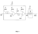
- FIG. 1 It shows schematically a limiting device of the phase noise DL 30 according to the invention in its environment.
- a portion of a transmission line comprising a transmission module 20 and the device DL 30 according to the invention.
- Such a section can be placed anywhere on the transmission line between the transmitter and the receiver.
- the optical signal is carried over a length of 1550 nm.
- the optical signal is then cleaned by means SUP 32 for suppressing amplitude fluctuations around a mean amplitude value.
- the output optical signal SO out obtained is transmitted on the transmission line.
- the phase noise limiting device 30 is placed at a null dispersion point NDP, that is to say at a point where the effects of the chromatic dispersion have been canceled.
- Such compensation is implemented upstream of the device for limiting the non-linear phase noise DL 30, in a manner known to those skilled in the art, for example within an MT transmission module such as that of FIG. figure 1 .
- Such a module MT generally comprises a span of optical fiber 21 transmission.
- This is, for example, a standard fiber Standard Single-Mode Fiber (SSMF). It can also be a fiber LEAF TM (Large Effective Area Fiber) or TRUE WAVE TM or any other optical fiber line positive chromatic dispersion.
- SSMF Standard Fiber Standard Single-Mode Fiber
- LEAF TM Large Effective Area Fiber
- TRUE WAVE TM any other optical fiber line positive chromatic dispersion.
- Such a section may have a length of one hundred kilometers.
- EDFA type Erbium Doped Fiber Amplifier
- This amplifier is intended to amplify the optical signal which has undergone attenuations of its average amplitude value. during transmission on the optical fiber 21 and which must be regenerated regularly.
- the transmission module MT also comprises means for compensating the chromatic dispersion, typically a DCF 23 (Dispersion Compensating Fiber) fiber, with a negative chromatic dispersion, the length of which is chosen so that it exactly compensates for the accumulated chromatic dispersion. by the optical signal in the fiber 21.
- the output of the DCF compensation fiber constitutes a null dispersion point NDP.
- the transmitted modulated optical signal has a constant average amplitude value, over which the ASE noise is superimposed.
- the transmission module MT may also comprise a second amplifier 24 placed downstream of the DCF compensation fiber 23, which makes it possible to output an optical signal whose amplitude level is adapted to the amplitude level. input required by the amplitude fluctuation suppression means 32 according to the invention.
- the DL phase noise limiting device 30 implements the steps of a non-linear phase noise limiting method, which will now be described in relation to the figure 2 .
- Such a method implements, on reception of an optical input signal SO in a step of suppressing the amplitude fluctuations affecting the optical signal of the M-PSK type.
- the output optical signal SO out obtained is "cleaned", which has the effect of avoiding the generation of non-linear phase noise in the downstream portion of the transmission line and therefore its accumulation along this line.
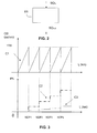
- FIG. 3 It shows schematically a first curve C1 changing chromatic dispersion along the transmission line. It highlights a succession of chromatic dispersion peaks (upstream of the DC compensation means) and NPC1 to NDP4 null dispersion points.
- a second curve C2 schematically shows an example of evolution of nonlinear phase noise along the transmission line in the absence of devices according to the invention. It can be seen that the noise level increases rapidly after each fiber section.
- a third curve C3 shows an example of evolution of the phase noise when placing phase noise limitation devices according to the invention at zero dispersion points NDP1 to NDP4. The increase in nonlinear phase noise level is much more limited. It will be noted that, depending on the engineering rules applied by the operator and on the selection of the transmission fiber sections, it is possible to completely prevent the appearance of non-linear phase noise between two devices according to the invention.
- the means for suppressing amplitude fluctuations DL30 comprise a transparent saturable type optical component.
- a transparent saturable type optical component may be, for example, made by inserting an absorbent saturable in a cavity constituting a multi-wave interferometer. This device closes the power, which is the modulus of the square of the amplitude of the electric field of the signal to a constant value P out 1 when the received optical signal has an input power P in the device which is greater than a threshold predetermined P in1 .
- the schema SCH 1 illustrates an evolution of the reflectivity R of the cavity as well as the output power of the device P out as a function of the power P in of the input optical signal. It shows that the evolution curve of the output power P out of the device as a function of the power P in of the input optical signal has a plateau P out 1 for an interval I of values of the input power.
- the SCH 2 diagram illustrates the fluctuations of the average value of the input power P in , when its value is included in the interval 1.
- the SCH3 scheme highlights the fact that the saturable transparency suppresses amplitude fluctuations around of the value P in1 and provides an output signal whose power is constant at the value P out1 .
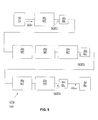
- the OTS transmission system 100 comprises a Tx transmitter 10 capable of transmitting an optical signal SO modulated in phase according to an M-PSK format. It further comprises a plurality of transmission modules MT1 to MTN, N integer greater than or equal to 1.
- N was chosen to be 6, but the invention is not limited to this particular case. They are arranged in groups, a first group formed of the transmission module MT 201 which provides a null dispersion point NDP1, a second group formed of the modules MT 20 2 , 20 3 and 20 4 at the output of which lies the point of zero dispersion. NDP2 and a third group consisting of MT modules 5 5 , 6 6 at the end of which is the point of zero dispersion NDP3.
- the transmission system 100 comprises a plurality of nonlinear phase noise limiting devices DL 30, placed regularly along the transmission line.
- 3 devices DL 30 1 , 2 , 3 are shown. They are placed respectively at zero dispersion points NDP1, NDP2 and NDP3.
- the OTS transmission system finally comprises a receiver Rx 40 capable of receiving the transmitted optical signal SO out .
Landscapes
- Physics & Mathematics (AREA)
- Electromagnetism (AREA)
- Engineering & Computer Science (AREA)
- Computer Networks & Wireless Communication (AREA)
- Signal Processing (AREA)
- Nonlinear Science (AREA)
- Optical Communication System (AREA)
Abstract
Description
- Le domaine de l'invention est celui des télécommunications, et plus particulièrement des télécommunications par fibres optiques.
- La présente invention concerne un dispositif de limitation du bruit de phase non-linéaire affectant un signal optique modulé en phase à amplitude constante transmis sur une ligne de transmission par fibre optique.
- Elle s'applique en particulier à un signal optique modulé en phase à amplitude ou puissance constante, notamment selon un format de type M-PSK (Phase Shift Keying), par exemple de type B-PSK (Binary), Q-PSK (Quaternary) ou encore 2N-PSK.
- Ce type de format est de plus en plus utilisé aujourd'hui pour les transmissions par fibres optiques longues distances. Un avantage de ce type de format est qu'il peut être couplé à une détection cohérente et à des algorithmes de traitement du signal numérique (DSP en anglais pour Digital Signal Processing) mis en oeuvre dans un circuit électronique dédié, ce qui permet de compenser les imperfections introduites par le canal de propagation, comme la dispersion chromatique (DC) et la PMD (Polarization Mode Dispersion) accumulées le long de la ligne de transmission par le signal optique.
- En effet, la détection cohérente est linéaire vis-à-vis du signal et permet d'accéder à l'amplitude et à la phase du signal optique, et d'en corriger, si nécessaire, les imperfections (notamment la DC et la PMD) numériquement via de tels algorithmes de DSP. Au contraire, la détection quadratique est proportionnelle au carré du champ du signal optique, ce qui a pour effet d'effacer l'information de phase. Elle ne permet donc pas d'effectuer un traitement du signal numérique efficace, ni de compenser la DC et la PMD.
- Les modulations de phase de type M-PSK sont en outre des modulations multi-niveaux qui présentent l'avantage d'avoir un débit symbole inférieur au débit binaire, ce qui permet une montée en débit supérieure à celle permise par les composants RF et opto-électroniques de la ligne de transmission. En effet, de tels composants sont limités en bande passante électrique à des fréquences bien inférieures à 100 GHz (typiquement 50 Ghz aujourd'hui). Ainsi, des lignes de transmission à 100 Gb/s sont aujourd'hui réalisables avec un format M-PSK, alors qu'elles ne le sont pas avec un format implémentant une modulation d'amplitude dite OOK (pour On-Off Keying) pour laquelle le débit symbole est égal au débit binaire.
- Un inconvénient majeur du format modulé en phase de type M-PSK est d'être sensible aux distorsions introduites par les effets non linéaires excités dans la fibre optique de transmission, en particulier à l'effet Kerr.
- L'effet Kerr est responsable d'une modulation de l'indice de réfraction de la fibre optique de transmission fonction de l'intensité du signal optique transmis. Une telle modulation provoque une variation de la phase du signal optique transmis qui dépend de sa puissance.
- L'effet Kerr est excité par le bruit d'amplitude affectant le signal optique, lui-même engendré par le bruit d'émission spontanée amplifié (ou ASE en anglais pour Amplified Spontaneous Emission) généré par la cascade d'amplificateurs optiques régulièrement introduits le long de la ligne de transmission pour régénérer l'amplitude du signal optique transmis. Les fluctuations d'amplitude ou bruit d'amplitude générées par le bruit ASE affectent le signal optique en agissant sur l'indice de réfraction de la fibre optique via l'effet Kerr. Elles créent des fluctuations de la phase (ou bruit de phase) du signal proportionnelles à la puissance instantanée de ce dernier. Ces fluctuations de phase sont d'autant plus grandes que la puissance instantanée du signal optique est plus élevée. Or, avec une modulation de type M-PSK, c'est la phase du signal optique qui porte les données binaires d'information utile. Il en résulte que ce bruit de phase non-linéaire va progressivement polluer l'information utile portée par le signal optique.
- Le document
EP1544669 décrit un procédé et un dispositif de limitation de bruit de phase généré par une ligne de transmission par fibre optique sur un signal optique modulé selon le format D-PSK (pour Differential Phase Shift Keying). Un tel dispositif comprend des moyens de conversion du signal optique transmis en un signal modulé en amplitude de type OOK. Une telle conversion de format a pour effet de convertir aussi le bruit de phase en bruit d'amplitude affectant les "1" et les "0" du signal OOK. Le dispositif de limitation comprend en outre des moyens de suppression des fluctuations d'amplitude sur les symboles 0 et sur les symboles 1 du signal converti et des moyens de conversion inverse du signal converti en un signal modulé en phase après suppression des fluctuations d'amplitude. - Selon un mode de réalisation, les moyens de suppression de fluctuations d'amplitude sont réalisés par un absorbant saturable idéal afin de stabiliser les fluctuations d'amplitude sur les "1" et les "0" du signal optique de type OOK. Il s'agit d'un composant optique passif simple à mettre en oeuvre.
- Un premier inconvénient d'un tel dispositif est qu'il nécessite une suppression des fluctuations d'amplitude sur les deux niveaux d'intensité "1" et "0", ce qui est difficile à réaliser, car cette suppression à deux niveaux exige de l'absorbant saturable qu'il présente une fonction de transfert proche de l'idéal en forme de marche d'escalier. Or les composants existants assurent un nettoyage très efficace des "0" mais ils sont moins performants sur les niveaux "1 ".
- Un deuxième inconvénient d'un tel dispositif est sa complexité et son coût, dus à la présence de deux convertisseurs phase-amplitude et amplitude-phase.
- L'invention vient améliorer la situation à l'aide d'un dispositif de limitation du bruit de phase non-linéaire affectant un signal optique modulé en phase à amplitude moyenne constante transmis sur une ligne de transmission.
- Selon l'invention, ledit dispositif étant placé en un point de dispersion nulle de la ligne de transmission, il est apte à mettre en oeuvre des moyens de suppression des fluctuations d'amplitude dudit signal optique autour de sa valeur moyenne.
- Le signal optique émis en entrée de la ligne de transmission présentait une valeur d'amplitude constante, les informations utiles étant portées par la modulation de phase. Au cours de la transmission sur une partie de la ligne, des fluctuations d'amplitude sont apparues autour de sa valeur constante d'entrée. En supprimant les fluctuations d'amplitude autour de cette valeur d'amplitude moyenne du signal optique transmis, le dispositif selon l'invention permet de maintenir l'amplitude du signal optique constante et donc de limiter l'accumulation du bruit de phase non-linéaire dû au bruit d'ASE sur un tronçon de fibre optique aval de la ligne de transmission. En effet, ce sont les fluctuations d'amplitude qui, en modifiant l'indice non linéaire de la fibre optique de la ligne de transmission, génèrent un bruit de phase d'une valeur proportionnelle à la puissance du signal optique. En supprimant les fluctuations d'amplitude sur le signal présenté en entrée d'un tronçon aval de fibre optique, le dispositif selon l'invention supprime la cause d'apparition du bruit de phase supplémentaire.
- Un tel dispositif est placé en un point de dispersion chromatique cumulée nulle, c'est-à-dire en un point où l'action de la dispersion chromatique sur le signal optique transmis est nulle. En un tel point, les fluctuations d'amplitude du signal optique transmis sont dues uniquement au bruit d'ASE des amplificateurs optiques de la ligne de transmission.
- Ainsi, l'invention repose sur une approche tout à fait nouvelle et inventive qui permet de limiter l'accumulation de bruit de phase tout au long d'une ligne de transmission, en nettoyant directement le signal optique modulé en phase, de façon à présenter en entrée d'un tronçon de fibre optique un signal optique modulé en phase dont l'amplitude est constante, sans fluctuations d'amplitude à l'origine de la génération de bruit de phase non linéaire.
- On comprendra que, si du bruit de phase s'est accumulé en amont du dispositif selon l'invention, il ne sera pas supprimé, mais le dispositif permet d'éviter que du bruit de phase supplémentaire ne s'accumule en aval du dispositif.
- Avec l'invention, il n'est donc plus nécessaire de procéder à une conversion du signal optique en un signal modulé en amplitude, par exemple selon le format de modulation d'amplitude OOK.
- L'invention propose ainsi une solution pour limiter l'accumulation du bruit de phase non-linéaire dans un signal optique transmis sur une ligne de transmission à fibre optique, qui est plus simple et moins coûteuse.
- Selon un aspect de l'invention, les moyens de suppression des fluctuations d'amplitude sont aptes à transformer un signal d'entrée présentant une amplitude moyenne comprise dans un intervalle prédéterminé en un signal de sortie présentant une amplitude de sortie constante.
- On comprend que les moyens de suppression des fluctuations d'amplitude selon l'invention présentent une fonction de transfert en marche d'escalier qui écrête les fluctuations d'amplitude autour d'un certain niveau d'amplitude d'entrée et fournit une amplitude de sortie constante.
- Selon un aspect de l'invention, les moyens de suppression des fluctuations d'amplitude sont réalisés par un composant de type transparent saturable.
- Un transparent saturable est un composant optique adapté à fournir, pour un signal optique d'entrée de puissance Pin supérieure à un seuil prédéterminé Pin1, un signal de sortie de puissance constante Pout 1. Par conséquent, il réalise, pour une puissance d'entrée incluse dans un intervalle de valeurs donné, la fonction de transfert en marche d'escalier qui coupe les fluctuations d'amplitude du signal d'entrée situées au-delà du seuil de puissance Pin1. Un tel composant est connu de l'homme de métier et décrit en détails dans le document intitulé "New Passive All-Optical Semiconductor Device for Bit-1 level noise reduction" par Oudar et al, publié dans les proceedings de la conférence Européenne "Lasers and Electro-Optics and the International Quantum Electronics CLEOE-IQEC 2007" en juin 2007.
- On notera toutefois que l'invention ne se limite pas à cet exemple de composant, mais qu'elle pourrait utiliser tout autre composant optique présentant la même fonction de transfert et ne modifiant pas la phase du signal optique qu'il traite.
- L'invention concerne en outre un procédé de limitation du bruit de phase non-linéaire dans un signal optique modulé en phase à amplitude moyenne constante transmis sur une ligne de transmission.
- Selon l'invention, ledit procédé met en oeuvre, en un point de dispersion nulle de la ligne de transmission, une étape de suppression des fluctuations d'amplitude dudit signal autour de sa valeur moyenne.
- L'invention concerne enfin un système de transmission par fibre optique (ligne de transmission) comprenant au moins un premier et un deuxième modules de transmission comprenant, le premier module de transmission comprenant :
- un tronçon (ou span en anglais) de fibre optique de transmission apte à transmettre le signal optique;
- des moyens d'amplification en ligne aptes à amplifier ledit signal optique en sortie du span de fibre optique;
- des moyens de compensation de dispersion chromatique aptes à fournir un signal optique amplifié pour lequel les effets de la dispersion chromatique sont annulés.
- Selon l'invention, un tel système comprend en sortie des moyens de compensation du premier module de transmission un dispositif de limitation du bruit de phase non-linéaire selon l'invention.
- Le point de sortie des moyens de compensation de dispersion chromatique constitue un point de dispersion nulle. C'est en ce point que l'on peut placer un dispositif de limitation du bruit de phase non-linéaire selon l'invention. On notera qu'un tel système peut comprendre une pluralité de modules de transmission. Dans ce cas, il dispose d'une pluralité de points de dispersion cumulée nulle, localisés régulièrement le long de la ligne de transmission. Ces points constituent des emplacements potentiels pour un dispositif de limitation du bruit de phase non-linéaire selon l'invention. Selon l'invention, un ou plusieurs dispositifs de limitation du bruit de phase peuvent donc avantageusement être placés en ces points, mais pas nécessairement en chaque point de dispersion nulle de la ligne de transmission.
- De façon avantageuse, un nombre de dispositifs de limitation de bruit de phase suffisant sur la ligne de transmission pour obtenir une limitation satisfaisante du bruit de phase non-linéaire est défini par des règles d'ingénierie de l'opérateur du réseau de transmission optique.
- D'autres avantages et caractéristiques de l'invention apparaîtront plus clairement à la lecture de la description suivante d'un mode de réalisation particulier de l'invention, donné à titre de simple exemple illustratif et non limitatif, et des dessins annexés, parmi lesquels :
- la
figure 1 présente un dispositif de limitation du bruit de phase non-linéaire selon l'invention dans son environnement; - la
figure 2 présente les étapes du procédé de limitation de bruit de phase selon l'invention; - la
figure 3 illustre l'évolution du bruit de phase non linéaire sur une ligne de transmission sans et avec l'invention;
lafigure 4 illustre la fonction de transfert d'un transparent saturable mis en oeuvre par le dispositif de limitation du bruit de phase non-linéaire selon un aspect de l'invention; et - la
figure 5 présente de façon schématique un exemple de système de transmission optique selon l'invention. - Le principe général de l'invention repose sur la suppression des fluctuations d'amplitude autour de la valeur moyenne d'amplitude du signal optique modulé en phase et transmis sur une ligne de transmission par fibre optique. Une telle suppression des fluctuations permet de maintenir la puissance du signal optique constante et ainsi de limiter la génération de bruit de phase non-linéaire au cours de la propagation par interaction du signal modulé en phase avec la fibre optique et excitation d'effets non linéaires.
- En relation avec la
figure 1 , on présente de façon schématique un dispositif de limitation du bruit de phase DL 30 selon l'invention, dans son environnement. Dans l'exemple de lafigure 1 , on a représenté une portion d'une ligne de transmission comprenant un module de transmission 20 et le dispositif DL 30 selon l'invention. Un tel tronçon peut être placé n'importe où sur la ligne de transmission entre l'émetteur et le récepteur. - Dans cet exemple, le signal optique est porté sur une longueur de 1550 nm.
- Le signal optique est alors nettoyé par les moyens SUP 32 de suppression des fluctuations d'amplitude autour d'une valeur d'amplitude moyenne. Le signal optique de sortie SOout obtenu est transmis sur la ligne de transmission.
- Selon l'invention, le dispositif de limitation du bruit de phase 30 est placé en un point de dispersion nulle NDP, c'est-à-dire en un point où les effets de la dispersion chromatique ont été annulés. Une telle compensation est mise en oeuvre en amont du dispositif de limitation du bruit de phase non-linéaire DL 30, de façon connue de l'homme de métier, par exemple au sein d'un module de transmission MT tel que celui de la
figure 1 . - Un tel module MT comprend généralement un span de fibre optique 21 de transmission. Il s'agit, à titre d'exemple, d'une fibre standard SSMF (Standard Single-Mode Fiber en anglais). Il peut s'agir également d'une fibre LEAF™ (Large effective Area Fiber) ou TRUE WAVE™ ou encore toute autre fibre optique de ligne à dispersion chromatique positive. Un tel tronçon peut avoir une longueur d'une centaine de kilomètres. Il est suivi d'un amplificateur optique 22 en ligne de type EDFA (Erbium Doped Fiber Amplifier) qui fonctionne sur la bande C. cet amplificateur a pour but d'amplifier le signal optique qui a subi des atténuations de sa valeur d'amplitude moyenne lors de la transmission sur la fibre optique 21 et qui doit être régénéré régulièrement.
- On notera toutefois que tout autre type d'amplificateur, notamment Raman pourrait être utilisé.
- Le module de transmission MT comprend aussi des moyens de compensation de la dispersion chromatique, typiquement une fibre DCF 23 (Dispersion Compensating Fiber), à dispersion chromatique négative, dont la longueur est choisie de façon à ce qu'elle compense exactement la dispersion chromatique accumulée par le signal optique dans la fibre 21. Il en résulte que la sortie de la fibre de compensation DCF constitue un point de dispersion nulle NDP. En ce point, le signal optique modulé transmis présente une valeur d'amplitude moyenne qui est constante, à laquelle se superpose le bruit d'ASE.
- On notera que le module de transmission MT peut comprendre aussi un deuxième amplificateur 24 placé en aval de la fibre de compensation DCF 23, qui permet de fournir en sortie un signal optique dont le niveau d'amplitude est adapté au niveau d'amplitude d'entrée requis par les moyens de suppression de fluctuations d'amplitude 32 selon l'invention.
- Le dispositif de limitation du bruit de phase DL 30 selon l'invention met en oeuvre les étapes d'un procédé de limitation du bruit de phase non linéaire, qui va maintenant être décrit en relation avec la
figure 2 . - Un tel procédé met en oeuvre, sur réception d'un signal optique d'entrée SOin une étape de suppression des fluctuations d'amplitude affectant le signal optique de type M-PSK. Le signal optique de sortie SOout obtenu est "nettoyé", ce qui a pour effet d'éviter la génération de bruit de phase non-linéaire dans la partie avale de la ligne de transmission et donc son accumulation le long de cette ligne.
- En relation avec la
figure 3 , on présente de façon schématique une première courbe C1 d'évolution de la dispersion chromatique le long de la ligne de transmission. Elle met en évidence une succession de pics de dispersion chromatique (en amont des moyens de compensation de la DC) et de points de dispersion nullle NDP1 à NDP4. Une deuxième courbe C2 montre de façon schématique un exemple d'évolution du bruit de phase non linéaire le long de la ligne de transmission en l'absence de dispositifs selon l'invention. On voit que le niveau de bruit augmente rapidement après chaque tronçon de fibre. Une troisième courbe C3 montre un exemple d'évolution du bruit de phase lorsqu'on place des dispositifs de limitation de bruit de phase selon l'invention aux points de dispersion nulle NDP1 à NDP4. L'augmentation du niveau de bruit de phase non linéaire est beaucoup plus limitée. On notera qu'en fonction des règles d'ingénierie appliquées par l'opérateur et du choix des tronçons de fibres de transmission, il est possible d'empêcher complètement l'apparition de bruit de phase non linéaire entre deux dispositifs selon l'invention. - Selon un aspect de l'invention, les moyens de suppression DL30 des fluctuations d'amplitude comprennent un composant optique de type transparent saturable. Un tel composant peut être, par exemple, réalisé en insérant un absorbant saturable dans une cavité constituant un interféromètre à ondes multiples. Ce dispositif écrête la puissance, qui est le module du carré de l'amplitude du champ électrique du signal à une valeur constante Pout 1lorsque le signal optique reçu présente une puissance Pin d'entrée dans le dispositif qui est supérieure à un seuil prédéterminé Pin1.
- En relation avec la
figure 4 , on présente une fonction de transfert d'un transparent saturable ainsi constitué. Le schéma SCH1 illustre une évolution de la réflectivité R de la cavité ainsi que de la puissance de sortie du dispositif Pout en fonction de la puissance Pin du signal optique d'entrée. Il montre que la courbe d'évolution de la puissance Pout de sortie du dispositif en fonction de la puissance Pin du signal optique d'entrée présente un palier Pout 1 pour un intervalle I de valeurs de la puissance d'entrée. Le schéma SCH2 illustre les fluctuations de la valeur moyenne de la puissance d'entrée Pin, lorsque sa valeur est incluse dans l'intervalle 1. Le schéma SCH3 met en évidence le fait que le transparent saturable supprime les fluctuations d'amplitude autour de la valeur Pin1 et fournit un signal de sortie dont la puissance est constante à la valeur Pout1. - Un exemple de système de transmission optique selon l'invention va maintenant être présenté en relation avec la
figure 4 . Le système de transmission OTS 100 comprend un émetteur Tx 10 apte à émettre un signal optique SO modulé en phase selon un format de type M-PSK. Il comprend en outre une pluralité de modules de transmission MT1 à MTN, N entier supérieur ou égal à 1. Dans l'exemple de lafigure 4 , on a choisi N égal à 6, mais l'invention n'est pas limitée à ce cas particulier. Ils sont disposés en groupes, un premier groupe formé du module de transmission MT 201 qui fournit un point de dispersion nulle NDP1, un deuxième groupe formé des modules MT 202, 203 et 204 en sortie duquel se trouve le point de dispersion nulle NDP2 et un troisième groupe formé des modules MT 205, 206 à l'issue duquel se trouve le point de dispersion nulle NDP3. - Selon l'invention, le système de transmission 100 comprend une pluralité de dispositifs DL 30 de limitation du bruit de phase non-linéaire, placés régulièrement le long de la ligne de transmission. Dans l'exemple de la
figure 5 ,3 dispositifs DL 301, 302, 303 sont représentés. Ils sont placés respectivement aux points de dispersion nulle NDP1, NDP2 et NDP3. - Le système de transmission OTS comprend enfin un récepteur Rx 40 apte à recevoir le signal optique transmis SOout.
- On notera toutefois que l'invention n'est pas limitée à cet exemple de configuration d'un système de transmission. L'exemple de la
figure 5 vise à illustrer les points suivants : - le dispositif de limitation du bruit de phase non-linéaire selon l'invention doit être placé en un point de dispersion nulle;
- un tel point de dispersion nulle peut avantageusement être fourni par un module de transmission tel que décrit précédemment;
- il n'est pas forcément nécessaire de placer un dispositif de limitation du bruit de phase non-linéaire selon l'invention en chaque point de dispersion nulle disponible le long de la ligne de transmission. Autrement dit, un système de transmission selon l'invention peut comprendre une séquence de plusieurs modules de transmission suivie d'un unique dispositif de limitation du bruit de phase non-linéaire; et
- les dispositifs de limitation du bruit de phase non-linéaire selon l'invention seront avantageusement placés régulièrement le long de la ligne de transmission, leur nombre et leur disposition étant fixés par des règles d'ingénierie du réseau pour réaliser un compromis entre coût et performances.
Claims (5)
- Dispositif de limitation du bruit de phase non-linéaire affectant un signal optique d'entrée modulé en phase à amplitude moyenne constante transmis sur une ligne de transmission, caractérisé en ce que, ledit dispositif étant placé en un point de dispersion nulle de la ligne de transmission, il est apte à mettre en oeuvre des moyens de suppression des fluctuations d'amplitude dudit signal optique autour d'une valeur moyenne .
- Dispositif de limitation du bruit de phase non-linéaire selon la revendication 1, caractérisé en ce que les moyens de suppression des fluctuations d'amplitude sont aptes à transformer un signal d'entrée présentant une amplitude moyenne comprise dans un intervalle prédéterminé en un signal de sortie présentant une amplitude de sortie constante.
- Dispositif de limitation du bruit de phase non-linéaire d'un signal optique modulé en phase selon la revendication 1, caractérisé en ce que les moyens de suppression des fluctuations d'amplitude sont réalisés par un composant de type transparent saturable.
- Procédé de limitation du bruit de phase non-linéaire d'un signal optique modulé en phase à amplitude moyenne constante transmis sur une ligne de transmission, caractérisé en ce que ledit procédé met en oeuvre, en un point de dispersion nulle de la ligne de transmission, une étape de suppression des fluctuations d'amplitude dudit signal autour de sa valeur moyenne.
- Système de transmission par fibre optique comprenant :- un émetteur apte à émettre un signal optique modulé en phase à amplitude constante;- au moins un module de transmission, comprenant :- un tronçon de fibre optique de transmission apte à transmettre le signal optique;- des moyens d'amplification en ligne aptes à amplifier ledit signal optique en sortie du tronçon de fibre optique;- des moyens de compensation de la dispersion chromatique accumulée par le signal optique dans ledit tronçon de fibre optique de transmission aptes à fournir un signal optique amplifié pour lequel les effets de la dispersion chromatiques sont annulés;caractérisé en ce qu'il comprend au moins un dispositif de limitation de bruit de phase, placé en sortie dudit module de transmission, ledit dispositif comprenant des moyens de suppression de fluctuations d'une amplitude dudit signal optique détecté autour d'une valeur moyenne.
Applications Claiming Priority (1)
| Application Number | Priority Date | Filing Date | Title |
|---|---|---|---|
| FR0854307 | 2008-06-27 |
Publications (2)
| Publication Number | Publication Date |
|---|---|
| EP2139129A1 true EP2139129A1 (fr) | 2009-12-30 |
| EP2139129B1 EP2139129B1 (fr) | 2013-03-27 |
Family
ID=39800454
Family Applications (1)
| Application Number | Title | Priority Date | Filing Date |
|---|---|---|---|
| EP09305539A Not-in-force EP2139129B1 (fr) | 2008-06-27 | 2009-06-12 | Procédé de limitation du bruit de phase non-lineaire d'un signal optique module en phase a amplitude constante et dispositif associé |
Country Status (2)
| Country | Link |
|---|---|
| US (1) | US20090324246A1 (fr) |
| EP (1) | EP2139129B1 (fr) |
Citations (3)
| Publication number | Priority date | Publication date | Assignee | Title |
|---|---|---|---|---|
| JP2000031901A (ja) * | 1998-07-08 | 2000-01-28 | Nippon Telegr & Teleph Corp <Ntt> | 光リミッタ回路 |
| EP1079552A2 (fr) * | 1999-08-26 | 2001-02-28 | Fujitsu Limited | Procédé, dispositif optique et système de transmission à fibres optiques |
| EP1544669A1 (fr) | 2003-12-19 | 2005-06-22 | France Telecom | Dispositif de régéneration d'un signal optique, utilisation d'un tel dispositif et installation comportant un tel dispositif |
Family Cites Families (2)
| Publication number | Priority date | Publication date | Assignee | Title |
|---|---|---|---|---|
| US6680787B1 (en) * | 1995-05-17 | 2004-01-20 | Btg International Limited | Optical communication systems |
| ES2323882T3 (es) * | 2005-05-11 | 2009-07-27 | Alcatel Lucent | Metodo para transmitir una señal optica en un sistema de transmision optica y sistema de transmision optica para implementar dicho metodo. |
-
2009
- 2009-06-12 EP EP09305539A patent/EP2139129B1/fr not_active Not-in-force
- 2009-06-26 US US12/492,715 patent/US20090324246A1/en not_active Abandoned
Patent Citations (3)
| Publication number | Priority date | Publication date | Assignee | Title |
|---|---|---|---|---|
| JP2000031901A (ja) * | 1998-07-08 | 2000-01-28 | Nippon Telegr & Teleph Corp <Ntt> | 光リミッタ回路 |
| EP1079552A2 (fr) * | 1999-08-26 | 2001-02-28 | Fujitsu Limited | Procédé, dispositif optique et système de transmission à fibres optiques |
| EP1544669A1 (fr) | 2003-12-19 | 2005-06-22 | France Telecom | Dispositif de régéneration d'un signal optique, utilisation d'un tel dispositif et installation comportant un tel dispositif |
Non-Patent Citations (2)
| Title |
|---|
| MATSUMOTO M: "Performance Improvement of Phase-Shift-Keying Signal Transmission By Means of Optical Limiters Using Four-Wave Mixing in Fibers", JOURNAL OF LIGHTWAVE TECHNOLOGY, IEEE SERVICE CENTER, NEW YORK, NY, US, vol. 23, no. 9, 1 September 2005 (2005-09-01), pages 2696 - 2701, XP011138934, ISSN: 0733-8724 * |
| SKOLD M ET AL: "Constellation diagram measurements of induced phase noise in a regenerating parametric amplifier", OPTICAL FIBER COMMUNICATION/NATIONAL FIBER OPTIC ENGINEERS CONFERENCE, 2008. OFC/NFOEC 2008. CONFERENCE ON, IEEE, PISCATAWAY, NJ, USA, 24 February 2008 (2008-02-24), pages 1 - 3, XP031391465, ISBN: 978-1-55752-856-8 * |
Also Published As
| Publication number | Publication date |
|---|---|
| EP2139129B1 (fr) | 2013-03-27 |
| US20090324246A1 (en) | 2009-12-31 |
Similar Documents
| Publication | Publication Date | Title |
|---|---|---|
| FR2685835A1 (fr) | Systeme de transmission tres longue distance sur fibre optique a compensation des distorsions a la reception. | |
| FR2685834A1 (fr) | Systeme de transmission numerique longue distance sur fibre optique a compensation a l'emission des distorsions. | |
| EP2171888B1 (fr) | Reseau optique passif bidirectionnel a haut debit, central optique et dispositif de terminaison de ligne associes | |
| US20090304391A1 (en) | Optical communications system having chromatic dispersion and polarization mode dispersion compensation | |
| EP0576358B1 (fr) | Procédé et système de transmission optique à très longue distance de solitons | |
| FR2707442A1 (fr) | Système de transmission sur fibre optique à compensation des distorsions en ligne. | |
| US20120243876A1 (en) | Use of semiconductor optical amplifiers-based intensity modulator in signal transmission | |
| EP0744844B1 (fr) | Procédé d'inscription de données binaires sur une onde porteuse, notamment optique, et système de transmission utilisant ce procédé | |
| CA2243858A1 (fr) | Structure interferometrique integree | |
| EP1087553A1 (fr) | Régénérateur de signaux optiques multiplexés en longueurs d'onde | |
| KR20040062332A (ko) | 대역 소거 필터를 적용한 eml 송신기 | |
| JP5856088B2 (ja) | 無中継長距離光ファイバ伝送システム | |
| FR2522225A1 (fr) | Dispositif de telecommunication a fibre optique unimodale | |
| EP0818896A1 (fr) | Système de transmission optique de données en format soliton | |
| EP2139129B1 (fr) | Procédé de limitation du bruit de phase non-lineaire d'un signal optique module en phase a amplitude constante et dispositif associé | |
| EP0598651B1 (fr) | Système de transmission optique, notamment pour réseau câblé de vidéocommunication | |
| EP0504777B1 (fr) | Système de transmission de signaux auxiliaires sur une liaison optique | |
| Molina-Luna et al. | Alternative to Super-PON downstream transmitter using a directly-modulated SOA | |
| Raj et al. | Adaptive neuro-fuzzy inference system-based nonlinear equalizer for CO-OFDM systems | |
| EP1511200B1 (fr) | Dispositif de régénération d'un signal optique et procédé correspondant. | |
| EP0849898B1 (fr) | Répéteur pour système de transmission à fibre optique à signaux solitons | |
| EP1311079B1 (fr) | Système de transmission de signal optique à phase contrôlée | |
| FR2688966A1 (fr) | Systeme de transmission tres longue distance sur fibre optique a compensation des distorsions a la reception. | |
| FR3026585A1 (fr) | Systeme de transmission a fibre optique monomode pour reseau d'acces | |
| Gu | Impact of Digital Modulation on Optical Fiber Communication |
Legal Events
| Date | Code | Title | Description |
|---|---|---|---|
| PUAI | Public reference made under article 153(3) epc to a published international application that has entered the european phase |
Free format text: ORIGINAL CODE: 0009012 |
|
| AK | Designated contracting states |
Kind code of ref document: A1 Designated state(s): AT BE BG CH CY CZ DE DK EE ES FI FR GB GR HR HU IE IS IT LI LT LU LV MC MK MT NL NO PL PT RO SE SI SK TR |
|
| 17P | Request for examination filed |
Effective date: 20100611 |
|
| 17Q | First examination report despatched |
Effective date: 20100706 |
|
| GRAP | Despatch of communication of intention to grant a patent |
Free format text: ORIGINAL CODE: EPIDOSNIGR1 |
|
| RIN1 | Information on inventor provided before grant (corrected) |
Inventor name: GOSSET, CHRISTOPHE Inventor name: PINCEMIN, M. ERWAN |
|
| GRAS | Grant fee paid |
Free format text: ORIGINAL CODE: EPIDOSNIGR3 |
|
| REG | Reference to a national code |
Ref country code: DE Ref legal event code: R079 Ref document number: 602009014365 Country of ref document: DE Free format text: PREVIOUS MAIN CLASS: H04B0010180000 Ipc: H04B0010251300 |
|
| GRAA | (expected) grant |
Free format text: ORIGINAL CODE: 0009210 |
|
| AK | Designated contracting states |
Kind code of ref document: B1 Designated state(s): AT BE BG CH CY CZ DE DK EE ES FI FR GB GR HR HU IE IS IT LI LT LU LV MC MK MT NL NO PL PT RO SE SI SK TR |
|
| REG | Reference to a national code |
Ref country code: GB Ref legal event code: FG4D Free format text: NOT ENGLISH |
|
| RIC1 | Information provided on ipc code assigned before grant |
Ipc: H04B 10/2543 20130101ALI20130219BHEP Ipc: H04B 10/2513 20130101AFI20130219BHEP |
|
| REG | Reference to a national code |
Ref country code: CH Ref legal event code: EP |
|
| REG | Reference to a national code |
Ref country code: AT Ref legal event code: REF Ref document number: 603986 Country of ref document: AT Kind code of ref document: T Effective date: 20130415 |
|
| REG | Reference to a national code |
Ref country code: IE Ref legal event code: FG4D Free format text: LANGUAGE OF EP DOCUMENT: FRENCH |
|
| REG | Reference to a national code |
Ref country code: DE Ref legal event code: R096 Ref document number: 602009014365 Country of ref document: DE Effective date: 20130523 |
|
| PG25 | Lapsed in a contracting state [announced via postgrant information from national office to epo] |
Ref country code: SE Free format text: LAPSE BECAUSE OF FAILURE TO SUBMIT A TRANSLATION OF THE DESCRIPTION OR TO PAY THE FEE WITHIN THE PRESCRIBED TIME-LIMIT Effective date: 20130327 Ref country code: LT Free format text: LAPSE BECAUSE OF FAILURE TO SUBMIT A TRANSLATION OF THE DESCRIPTION OR TO PAY THE FEE WITHIN THE PRESCRIBED TIME-LIMIT Effective date: 20130327 Ref country code: BG Free format text: LAPSE BECAUSE OF FAILURE TO SUBMIT A TRANSLATION OF THE DESCRIPTION OR TO PAY THE FEE WITHIN THE PRESCRIBED TIME-LIMIT Effective date: 20130627 Ref country code: NO Free format text: LAPSE BECAUSE OF FAILURE TO SUBMIT A TRANSLATION OF THE DESCRIPTION OR TO PAY THE FEE WITHIN THE PRESCRIBED TIME-LIMIT Effective date: 20130627 |
|
| REG | Reference to a national code |
Ref country code: AT Ref legal event code: MK05 Ref document number: 603986 Country of ref document: AT Kind code of ref document: T Effective date: 20130327 |
|
| REG | Reference to a national code |
Ref country code: LT Ref legal event code: MG4D |
|
| PG25 | Lapsed in a contracting state [announced via postgrant information from national office to epo] |
Ref country code: GR Free format text: LAPSE BECAUSE OF FAILURE TO SUBMIT A TRANSLATION OF THE DESCRIPTION OR TO PAY THE FEE WITHIN THE PRESCRIBED TIME-LIMIT Effective date: 20130628 Ref country code: LV Free format text: LAPSE BECAUSE OF FAILURE TO SUBMIT A TRANSLATION OF THE DESCRIPTION OR TO PAY THE FEE WITHIN THE PRESCRIBED TIME-LIMIT Effective date: 20130327 Ref country code: FI Free format text: LAPSE BECAUSE OF FAILURE TO SUBMIT A TRANSLATION OF THE DESCRIPTION OR TO PAY THE FEE WITHIN THE PRESCRIBED TIME-LIMIT Effective date: 20130327 Ref country code: SI Free format text: LAPSE BECAUSE OF FAILURE TO SUBMIT A TRANSLATION OF THE DESCRIPTION OR TO PAY THE FEE WITHIN THE PRESCRIBED TIME-LIMIT Effective date: 20130327 |
|
| REG | Reference to a national code |
Ref country code: CH Ref legal event code: PUE Owner name: ORANGE, FR Free format text: FORMER OWNER: FRANCE TELECOM, FR |
|
| REG | Reference to a national code |
Ref country code: NL Ref legal event code: VDEP Effective date: 20130327 |
|
| RAP2 | Party data changed (patent owner data changed or rights of a patent transferred) |
Owner name: ORANGE |
|
| PG25 | Lapsed in a contracting state [announced via postgrant information from national office to epo] |
Ref country code: HR Free format text: LAPSE BECAUSE OF FAILURE TO SUBMIT A TRANSLATION OF THE DESCRIPTION OR TO PAY THE FEE WITHIN THE PRESCRIBED TIME-LIMIT Effective date: 20130327 |
|
| PG25 | Lapsed in a contracting state [announced via postgrant information from national office to epo] |
Ref country code: CZ Free format text: LAPSE BECAUSE OF FAILURE TO SUBMIT A TRANSLATION OF THE DESCRIPTION OR TO PAY THE FEE WITHIN THE PRESCRIBED TIME-LIMIT Effective date: 20130327 Ref country code: ES Free format text: LAPSE BECAUSE OF FAILURE TO SUBMIT A TRANSLATION OF THE DESCRIPTION OR TO PAY THE FEE WITHIN THE PRESCRIBED TIME-LIMIT Effective date: 20130708 Ref country code: SK Free format text: LAPSE BECAUSE OF FAILURE TO SUBMIT A TRANSLATION OF THE DESCRIPTION OR TO PAY THE FEE WITHIN THE PRESCRIBED TIME-LIMIT Effective date: 20130327 Ref country code: RO Free format text: LAPSE BECAUSE OF FAILURE TO SUBMIT A TRANSLATION OF THE DESCRIPTION OR TO PAY THE FEE WITHIN THE PRESCRIBED TIME-LIMIT Effective date: 20130327 Ref country code: EE Free format text: LAPSE BECAUSE OF FAILURE TO SUBMIT A TRANSLATION OF THE DESCRIPTION OR TO PAY THE FEE WITHIN THE PRESCRIBED TIME-LIMIT Effective date: 20130327 Ref country code: IS Free format text: LAPSE BECAUSE OF FAILURE TO SUBMIT A TRANSLATION OF THE DESCRIPTION OR TO PAY THE FEE WITHIN THE PRESCRIBED TIME-LIMIT Effective date: 20130727 Ref country code: PT Free format text: LAPSE BECAUSE OF FAILURE TO SUBMIT A TRANSLATION OF THE DESCRIPTION OR TO PAY THE FEE WITHIN THE PRESCRIBED TIME-LIMIT Effective date: 20130729 Ref country code: NL Free format text: LAPSE BECAUSE OF FAILURE TO SUBMIT A TRANSLATION OF THE DESCRIPTION OR TO PAY THE FEE WITHIN THE PRESCRIBED TIME-LIMIT Effective date: 20130327 Ref country code: AT Free format text: LAPSE BECAUSE OF FAILURE TO SUBMIT A TRANSLATION OF THE DESCRIPTION OR TO PAY THE FEE WITHIN THE PRESCRIBED TIME-LIMIT Effective date: 20130327 |
|
| PG25 | Lapsed in a contracting state [announced via postgrant information from national office to epo] |
Ref country code: PL Free format text: LAPSE BECAUSE OF FAILURE TO SUBMIT A TRANSLATION OF THE DESCRIPTION OR TO PAY THE FEE WITHIN THE PRESCRIBED TIME-LIMIT Effective date: 20130327 Ref country code: CY Free format text: LAPSE BECAUSE OF FAILURE TO SUBMIT A TRANSLATION OF THE DESCRIPTION OR TO PAY THE FEE WITHIN THE PRESCRIBED TIME-LIMIT Effective date: 20130327 |
|
| BERE | Be: lapsed |
Owner name: FRANCE TELECOM Effective date: 20130630 |
|
| PG25 | Lapsed in a contracting state [announced via postgrant information from national office to epo] |
Ref country code: DK Free format text: LAPSE BECAUSE OF FAILURE TO SUBMIT A TRANSLATION OF THE DESCRIPTION OR TO PAY THE FEE WITHIN THE PRESCRIBED TIME-LIMIT Effective date: 20130327 Ref country code: MC Free format text: LAPSE BECAUSE OF FAILURE TO SUBMIT A TRANSLATION OF THE DESCRIPTION OR TO PAY THE FEE WITHIN THE PRESCRIBED TIME-LIMIT Effective date: 20130327 |
|
| PLBE | No opposition filed within time limit |
Free format text: ORIGINAL CODE: 0009261 |
|
| REG | Reference to a national code |
Ref country code: CH Ref legal event code: PL |
|
| STAA | Information on the status of an ep patent application or granted ep patent |
Free format text: STATUS: NO OPPOSITION FILED WITHIN TIME LIMIT |
|
| GBPC | Gb: european patent ceased through non-payment of renewal fee |
Effective date: 20130627 |
|
| PG25 | Lapsed in a contracting state [announced via postgrant information from national office to epo] |
Ref country code: IT Free format text: LAPSE BECAUSE OF FAILURE TO SUBMIT A TRANSLATION OF THE DESCRIPTION OR TO PAY THE FEE WITHIN THE PRESCRIBED TIME-LIMIT Effective date: 20130327 |
|
| 26N | No opposition filed |
Effective date: 20140103 |
|
| REG | Reference to a national code |
Ref country code: DE Ref legal event code: R119 Ref document number: 602009014365 Country of ref document: DE Effective date: 20140101 |
|
| REG | Reference to a national code |
Ref country code: IE Ref legal event code: MM4A |
|
| REG | Reference to a national code |
Ref country code: FR Ref legal event code: ST Effective date: 20140228 |
|
| PG25 | Lapsed in a contracting state [announced via postgrant information from national office to epo] |
Ref country code: BE Free format text: LAPSE BECAUSE OF NON-PAYMENT OF DUE FEES Effective date: 20130630 |
|
| PG25 | Lapsed in a contracting state [announced via postgrant information from national office to epo] |
Ref country code: LI Free format text: LAPSE BECAUSE OF NON-PAYMENT OF DUE FEES Effective date: 20130630 Ref country code: IE Free format text: LAPSE BECAUSE OF NON-PAYMENT OF DUE FEES Effective date: 20130612 Ref country code: CH Free format text: LAPSE BECAUSE OF NON-PAYMENT OF DUE FEES Effective date: 20130630 Ref country code: GB Free format text: LAPSE BECAUSE OF NON-PAYMENT OF DUE FEES Effective date: 20130627 Ref country code: DE Free format text: LAPSE BECAUSE OF NON-PAYMENT OF DUE FEES Effective date: 20140101 |
|
| PG25 | Lapsed in a contracting state [announced via postgrant information from national office to epo] |
Ref country code: FR Free format text: LAPSE BECAUSE OF NON-PAYMENT OF DUE FEES Effective date: 20130701 |
|
| PG25 | Lapsed in a contracting state [announced via postgrant information from national office to epo] |
Ref country code: MT Free format text: LAPSE BECAUSE OF FAILURE TO SUBMIT A TRANSLATION OF THE DESCRIPTION OR TO PAY THE FEE WITHIN THE PRESCRIBED TIME-LIMIT Effective date: 20130327 |
|
| PG25 | Lapsed in a contracting state [announced via postgrant information from national office to epo] |
Ref country code: TR Free format text: LAPSE BECAUSE OF FAILURE TO SUBMIT A TRANSLATION OF THE DESCRIPTION OR TO PAY THE FEE WITHIN THE PRESCRIBED TIME-LIMIT Effective date: 20130327 |
|
| PG25 | Lapsed in a contracting state [announced via postgrant information from national office to epo] |
Ref country code: MK Free format text: LAPSE BECAUSE OF FAILURE TO SUBMIT A TRANSLATION OF THE DESCRIPTION OR TO PAY THE FEE WITHIN THE PRESCRIBED TIME-LIMIT Effective date: 20130327 Ref country code: HU Free format text: LAPSE BECAUSE OF FAILURE TO SUBMIT A TRANSLATION OF THE DESCRIPTION OR TO PAY THE FEE WITHIN THE PRESCRIBED TIME-LIMIT; INVALID AB INITIO Effective date: 20090612 Ref country code: LU Free format text: LAPSE BECAUSE OF NON-PAYMENT OF DUE FEES Effective date: 20130612 |