EP1544662A1 - Beobachtungssystem und -verfahren - Google Patents
Beobachtungssystem und -verfahren Download PDFInfo
- Publication number
- EP1544662A1 EP1544662A1 EP04028132A EP04028132A EP1544662A1 EP 1544662 A1 EP1544662 A1 EP 1544662A1 EP 04028132 A EP04028132 A EP 04028132A EP 04028132 A EP04028132 A EP 04028132A EP 1544662 A1 EP1544662 A1 EP 1544662A1
- Authority
- EP
- European Patent Office
- Prior art keywords
- pixels
- modulator
- observation
- state
- radiation
- Prior art date
- Legal status (The legal status is an assumption and is not a legal conclusion. Google has not performed a legal analysis and makes no representation as to the accuracy of the status listed.)
- Granted
Links
- 238000000034 method Methods 0.000 title claims abstract description 15
- 230000005855 radiation Effects 0.000 claims description 23
- 238000003384 imaging method Methods 0.000 claims description 16
- 238000005286 illumination Methods 0.000 claims description 6
- 238000013507 mapping Methods 0.000 claims description 4
- 230000003287 optical effect Effects 0.000 abstract description 5
- 230000003190 augmentative effect Effects 0.000 description 6
- 210000003128 head Anatomy 0.000 description 4
- 238000011161 development Methods 0.000 description 2
- 239000011159 matrix material Substances 0.000 description 2
- 239000000203 mixture Substances 0.000 description 2
- 210000001747 pupil Anatomy 0.000 description 2
- 230000002238 attenuated effect Effects 0.000 description 1
- 210000004204 blood vessel Anatomy 0.000 description 1
- 210000000988 bone and bone Anatomy 0.000 description 1
- 230000001771 impaired effect Effects 0.000 description 1
- 238000012423 maintenance Methods 0.000 description 1
- 238000005259 measurement Methods 0.000 description 1
- 238000012549 training Methods 0.000 description 1
- 230000000007 visual effect Effects 0.000 description 1
Images
Classifications
-
- G—PHYSICS
- G02—OPTICS
- G02B—OPTICAL ELEMENTS, SYSTEMS OR APPARATUS
- G02B27/00—Optical systems or apparatus not provided for by any of the groups G02B1/00 - G02B26/00, G02B30/00
- G02B27/01—Head-up displays
- G02B27/017—Head mounted
-
- G—PHYSICS
- G02—OPTICS
- G02B—OPTICAL ELEMENTS, SYSTEMS OR APPARATUS
- G02B27/00—Optical systems or apparatus not provided for by any of the groups G02B1/00 - G02B26/00, G02B30/00
- G02B27/01—Head-up displays
- G02B27/0101—Head-up displays characterised by optical features
- G02B2027/014—Head-up displays characterised by optical features comprising information/image processing systems
Definitions
- the invention relates to an observation system and observation method, in which superimpose an observer an object to be viewed with other image information can.
- Such overlays can be done electronically, for example, that to viewing object is recorded by means of a camera.
- the by means of the camera generated image data are mixed in a computer with the image data to be overlaid and then fed to a viewer by means of a display.
- the disadvantage here is that a direct view of the viewer is no longer given. The viewer can own his environment no longer directly perceive what its orientation ability clearly disadvantageous impaired.
- an optical mixture in which a splitter mirror or a Divider cubes the object to be viewed on the one hand and the image information to be overlaid (augmented portion) are superimposed by a display unit on the other hand.
- a splitter mirror or a Divider cubes the object to be viewed on the one hand and the image information to be overlaid (augmented portion) are superimposed by a display unit on the other hand.
- This is in the Usually carried out so that the two superimposed images in pupil planes are located. Therefore, a location relationship of the augmented portion with respect to the real missing Object.
- the superimposition takes place in that an optical transparency (by means of Divider cube or divider mirror) on the entire image surface for the viewer is present.
- the real scene is thus superimposed in terms of area completely with the augmented portion, being the transparency only indirectly by changing the brightness of the real object (for example by aperture) and the augmented portion (variation of the brightness of the Display) can be set.
- an observation system and a To provide observational procedures to address the possibilities of Overlaying a perceptible real object with further image information improved and become more flexible.
- the object is achieved by an observation system with a modulator, which comprises a planar modulator region formed from a plurality of pixels control device connected to the modulator, by means of which the pixels are separated from one another independently in each case in a first and a second state can be brought, one Intermediate imaging optics, the object to be viewed on the area modulator area from which due to the imaging by means of the intermediate imaging optics on the Pixel striking radiation only the radiation enters an observation beam path, the encounters the pixel in the first state.
- This will make it possible to do so observing object precisely defined proportions in the observation beam path and thus to the eye of the beholder.
- the image contents of the other areas are the Viewer not fed and thus virtually "punched out".
- a stamped area presents as Such, of course, a picture information, so that the viewer a superposition of the observing object with the image information of the punched out area.
- the modulator is thus configured and arranged so that only those in the first State objects for an observer via the Observation beam are perceptible.
- control device is designed such that it from the pixels, the pixels in the second state switches together, a desired image information in the plane of represent planar Modulatör Kunststoffs. These may be markings such as e.g. arrows, Points, crosses or other simple figures act. It is also possible to desired Contours or surfaces represent. The only limit is the number of pixels and their size conditionally.
- transmissive modulators e.g. a transmissive LCD module
- the observation system may have a lighting unit that the flat Modulator area so acted upon by a lighting radiation, that only those on the second state of the pixel in the incident illumination radiation in the Observation beam passes. So you can the "punched out” image areas the To give viewers color. Thus, for example, the arrows in any color being represented.
- a particularly preferred embodiment of the observation system according to the invention is a display unit having a display and a display optics to provide, wherein the display optics generated by the display image on the flat Modulator Scheme maps and the display unit is arranged and designed such that from the radiation incident on the pixels due to imaging by means of the display optics only the radiation is coupled into the observation beam path, which is in the second State of the pixels.
- the punched image areas with any be populated with other image information. So it will be the desired overlay of the real object to be viewed with further image information for the viewer achieved.
- the controller may be arranged to drive each pixel so that the residence time of the pixel in the first and second state per unit time predetermined Values corresponds. This makes it possible, the punched out areas for the viewer to appear partially transparent. So he sees the punched out part with lesser Brightness compared to non-punched-out parts of the object to be viewed. This can Of course also be used that the complete object to be viewed with lower brightness is displayed. In this case, all pixels are alternately in switched the first and second state. It is also possible with this control the Brightness of the imprinted image sections mirrored image relative to the to set the object to be viewed freely.
- the observation system may be designed such that the observation beam path of a user is directly viewable or the one observation optics in the Observation beam path is provided, via which the user at the modulator can perceive the selected overlay image. This makes it possible, depending on the given Conditions to provide the desired observation system.
- the observation system can be designed, for example, as a device to be worn on the user's head. Such a device is also often referred to as HMD device (H ead M ounted D isplay device).
- HMD device H ead M ounted D isplay device
- the observation system can be realized in any conventional observation system in which an intermediate image is performed. It must be arranged in a suitable manner substantially only in the intermediate image plane of the modulator.
- the observation system can be designed in particular as a microscope. This can z. As in operations that are performed by means of such a microscope, further image content for the surgeon are recorded in the perceivable image of him, such as invisible blood vessels and bones or other.
- the intermediate imaging optics of the observation system can be used as focusable or autofocusable optics. educated . be. Furthermore, it is possible if that Observation system is designed as HMD device to provide a device, which detects the head position of the user and forwards this data to the control device, which in turn drives the pixels according to this data.
- the object is also solved by an observation method in which a to be observed Object on one of a plurality of pixels formed area modulator area of a Modulators are mapped from the pixels, which are independent of each other into a first one and a second state are switchable, the pixels are switched to the second state, together form a desired image information in the plane of the planar modulator reference and of the radiation impinging on the pixels due to the image, only the Radiation is directed into an observation beam path, which is in the first state pixels, so that for a viewer on the in the second state pixels are not perceptible.
- the area modulator area can further with a Illuminating radiation are acted upon, that only those in the second state the pixels in the observation beam path. This makes it possible that the desired image information displayed in color for a user becomes.
- Observation method is on the area modulator area a second image such imaged that of the due to the mapping of the second image on the pixels Radiation only the radiation is directed into the observation beam path, which is in the second state of the pixel.
- This method allows the object to be viewed shown superimposed with arbitrary image data in the simplest way for a user become.
- the pixels may each be so be controlled that their residence time in the first and second state per unit time given values. This can be a desired attenuation or Transparency of the object to be observed can be adjusted.
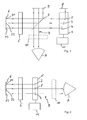
- Fig. 1 is a schematic representation of a first embodiment of the invention Observation system shown.
- the observation system comprises a modulator 1 comprising a plurality of pixels 2, 3, 4 having a planar Form modulator area.
- the modulator is here a tilting mirror matrix, the a plurality of arranged in rows and columns tilting mirrors, each in two different tilt positions are switchable.
- Fig. 1 are for simplicity of illustration only three tilting mirrors 2, 3, 4 shown schematically.
- the observation system further comprises an intermediate imaging optic 5 which is so relative to planar modulator region is arranged so that they are an object to be observed 6 on the planar modulator area maps.
- the area modulator area is in the Focus plane of the intermediate imaging optics 5.
- a beam splitter 7 is arranged, which is inclined by 45 ° relative to the optical axis of the intermediate imaging optics 5.
- the Observation system further comprises a first and a second beam trap 8, 9 and can Optionally, an observation optics 10 included in an observation beam B of the Observation system is arranged.
- the observation beam B runs here from the Modulator 1 via the beam splitter 7 to a schematically drawn eye A of a Beholder.
- a control device 11 is provided, by means of which the individual pixels 2, 3 and 4 independent of each other in the first and second state (here so the first and second tilt position) can be switched.
- the beam trajectories in the observation system located. It can be deduced from these ray curves that the object 6 (ie the points P1, P2 and P3) are mapped onto the area modulator area. From the pixels 2 - 4 the pixels 3 and 4 are in the first state and the pixel 2 in the second state. The Tilt position in the first state is such that the light of the corresponding object points P2 and P3 is reflected back in itself (ie back to the beam splitter 6) and at the beam splitter 6 is then reflected (at least in part) towards the eye A of the observer.
- the modulator is now preferably controlled by the control device 11 so that a desired image information generated by means of the pixels located in the second state becomes.
- a desired image information generated by means of the pixels located in the second state becomes.
- an arrow with the pixels in the second state may be considered as Image information to be displayed.
- the observation system can be designed, for example, as an HMD device ( H ead M ountedu D display device), that is to say as a display device which is to be worn on the head of a user.
- the image information represented by the pixels in the second state may serve to mark certain components for the user carrying the HMD device.
- One possible application is, for example, the maintenance of a machine. The user is looking at the machine by means of, for example, an arrow. marks the part to be replaced or serviced.
- the observation system is not limited to HMD applications. It can Rather, they are used in all technical applications in which an object has a Intermediate image is considered. An example of this is a microscope. This must then only so be converted that arranged in the intermediate image plane of the modulator 1 accordingly becomes. In the training as a microscope then the observation optics 10 is the microscope eyepiece.
- Fig. 2 is a second embodiment of the observation system according to the invention shown, wherein like elements as in Fig. 1 are denoted by the same reference numerals and to the description of which reference is made to the above statements.
- the shown in Fig. 2 Embodiment differs in that shown in FIG. 1 in that instead of the reflective modulator 1 a transmissive modulator 1 'is used, which in turn in the Focusing plane of the imaging optics 5 is arranged.
- the transmissive modulator 1 ' here For example, formed as an LCD module, which has a plurality of lines and columns arranged pixels, of which here again by way of example three pixels 2, 3 and 4 are drawn.
- the pixels transmit the light incident on them, while in the second state they reflect or absorb the light falling on them. Consequently enters the observation beam B only light that comes from pixels that are in the first state are located. In the example shown schematically here, this concerns the pixels 3 and 4 and thus the object points P2 and P3. The pixel 2 is in the second state, so that the object point P1 is imperceptible to the viewer.
- the Image information of the object 6 at the desired locations suppress.
- the pixel 2 (or the corresponding pixels) be switched between the first and second state back and forth. It is by the Dwell time of the pixel 2 in the first state to the dwell time of the pixel 2 in the second state (per unit of time) determines how strong the image information on the second pixel is compared to the Image information on the other pixels that are in the first state is attenuated becomes.
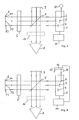
- Fig. 3 is a development of the embodiment shown in Fig. 1 is shown, wherein the same parts as in Fig. 1 are denoted by the same reference numerals and the description not repeated.
- the embodiment of Fig. 3 differs from that of Fig. 1 in that that instead of the first beam trap 8, a light source 12 is arranged, the light of a gives off predetermined color.
- the light source 12 for example, a light emitting diode be used.
- the light source 12 is arranged relative to the light modulator 1, that they illuminates the area modulator area, but only the light that is in the second state located pixels 2 is reflected in the observation beam path B. is coupled, as shown by the partially dashed beam path. In order to does not become the viewer's area of pixels in the second state dark but colored. When with the pixels in the second state an arrow is displayed and the light source 12 emits red light, this arrow is for the Viewer red.
- a lighting optics (not located).
- the illumination optics is preferably designed so that their Exit pupil is on the area modulator area.
- the image of the light source 12 on the light modulator 1 thus corresponds to the Köhler illumination in a microscope. This advantageously ensures that not the structure of the light source 12 on the flat Modulator range is shown, but that only the integral brightness component in each place of the area modulator area is evenly affected.
- Imaging optics are also omitted, especially if you have a planar Light source, such as an OLED (organic light emitting diode) is used.
- OLED organic light emitting diode
- Such a light source acts as a surface radiator, so that there is already a somewhat diffuse illumination.
- an OLED does not provide any recognizable structures, such as a filament a lamp on.
- FIG. 4 A further development of the embodiment of Fig. 1 is shown in Fig. 4, wherein the same Elements as in Fig. 1 are again denoted by the same reference numerals.
- the Embodiment of Fig. 4 differs from that in Fig. 1 in that instead of the first Beam trap 8, a display unit 13 with a display 14 and a display optics 15 is arranged actual.
- the display 14 may, for example, a self-luminous display or a be illuminated display.
- the display 14 is preferably also by means of the control unit 11 controlled, wherein the display 14 is preferably a flat display.
- the display 14 is imaged by means of the display optics 15 on the area modulator area.
- the display unit 13 is designed and arranged relative to the modulator 1, that only that of the Display 14 coming and the pixels incident light in the observation beam B which is reflected by the pixels which are in the second state. It is thus possible in the embodiment of Fig. 4, for a viewer targeted parts of the to cut out the object 6 to be viewed and at the same time in these cut-out parts other image information (from the display unit 13) to play. The viewer therefore sees a superposition of the object to be viewed with the further image information, wherein in Area of further image information the object is completely suppressed. In other words become the "punched out" by means of the pixels in the second state Image information of the object 6 filled with other image information.
- the Image information of the object 6 not completely "auszustanzen” but this Display image information with lower brightness. This is done by an appropriate Control of the pixels and the residence times in the first and second state possible. If one applies this to all pixels of the modulator, thus allowing a superposition of the Viewing object 6 with another image set so that always a desired Brightness ratio between the object under consideration 6 and the superimposed image available is. If the brightness of the object 6 changes over time, you can go through Measurement of the object brightness and a corresponding feedback via the control unit 10 even achieve that the desired brightness ratio (relative) regardless of the actual brightness of the object is maintained. This is of course with all Embodiments of the invention possible.
- the display 14 has a higher resolution than have the pixel size of the modulator 1 or the display 14 is by means of the display optics 15 reduced to the modulator area F shown.
- the intermediate imaging optics as be formed focusable optics which is preferably autofocus capable.
- These can be known Autofokussier Kunststoff be used.
- the observation system as an HMD device is formed, such siersysteme can also be used.
- the intermediate imaging optics 5 and optionally provided observation optics 10 preferably designed so that for the user a 1: 1 mapping the environment is passed through. The user thus sees the environment over the Intermediate imaging optics and the optionally provided observation optics 10 such as he would perceive them without the intermediate imaging optics 5 and the observation optics 10.
- the observation system can be designed so that a beam deflection laterally occurs outside, so that in the extreme case broadening of the eye base is effective and so that a slightly excessive stereo presentation can be done, but otherwise no Limitations of natural visual impressions is effected.
- Another particularly effective embodiment of the invention is that the described embodiments in an HMD device for each separate eyes available. This results in a stereo suitability of the system, with the augmenting objects (punched out areas) so in the respective planar Modulator range (for the left and right eye) are set to a stereoscopic Representation of the punched areas is effected.
- the two images areal in with the can interleave the resolution given by the pixels of the modulator. It deals is therefore a system in which an input image in an intermediate image on the spatial Modulator is mapped and on the intermediate image, a modulation or mixture with a second arbitrary image in any and preferably limited only by the Pixelabantelung Form can be performed in a flat manner.
Landscapes
- Physics & Mathematics (AREA)
- General Physics & Mathematics (AREA)
- Optics & Photonics (AREA)
- Control Of Indicators Other Than Cathode Ray Tubes (AREA)
- Mechanical Light Control Or Optical Switches (AREA)
- Liquid Crystal (AREA)
- Microscoopes, Condenser (AREA)
- Optical Modulation, Optical Deflection, Nonlinear Optics, Optical Demodulation, Optical Logic Elements (AREA)
Abstract
Description
- Fig. 1
- ein Beobachtungssystem gemäß einer ersten Ausführungsform;
- Fig. 2
- ein Beobachtungssystem gemäß einer zweiten Ausführungsform;
- Fig. 3
- ein Beobachtungssystem gemäß einer dritten Ausführungsform, und
- Fig. 4
- ein Beobachtungssystem gemäß einer vierten Ausführungsform.
Claims (13)
- Beobachtungssystem mit einem Modulator (1), der einen aus einer Mehrzahl von Pixeln (2, 3, 4) gebildeten flächigen Modulatorbereich umfaßt, einer mit dem Modulator (1) verbundenen Steuereinrichtung (11), mittels der die Pixel (2 - 4) voneinander unabhängig jeweils in einen ersten und einen zweiten Zustand schaltbar sind, einer Zwischenabbildungsoptik (5), die ein zu betrachtendes Objekt (6) auf den flächigen Modulatorbereich abbildet, wobei von der aufgrund der Abbildung mittels der Zwischenabbildungsoptik (5) auf die Pixel treffenden Strahlung nur die Strahlung in einen Beobachtungsstrahlengang (B) gelangt, die auf die sich im ersten Zustand befindenden Pixeln trifft.
- Beobachtungssystem nach Anspruch 1, bei dem die Steuereinrichtung (11) von den Pixeln (2 - 4) die Pixel (2) in den zweiten Zustand schaltet, die zusammen eine gewünschte Bildinformation in der Ebene des flächigen Modulatorbereichs darstellen.
- Beobachtungssystem nach einem der obigen Ansprüche, bei dem eine Beleuchtungseinheit (12) vorgesehen ist, die den flächigen Modulatorbereich so mit einer Beleuchturigsstrahlung. beaufschlagt, daß nur die auf die sich im zweiten Zustand befindenden Pixeln treffende Beleuchtungsstrahlung in den Beobächtungsstrahlengang (B) gelangt.
- Beobachtungssystem nach Anspruch 1 oder 2, bei dem eine eine Anzeige (14) und eine Anzeigeoptik (15) aufweisende Anzeigeeinheit (13) vorgesehen ist, wobei die Anzeigeoptik (15) ein mittels der Anzeige (14) erzeugtes Bild auf den flächigen Modulatorbereich abbildet und die Anzeigeeinheit (13) so angeordnet und ausgebildet ist, daß von der aufgrund der Abbildung mittels der Anzeigeoptik (15) auf die Pixel treffende Strahlung nur die Strahlung in den Beobachtungsstrahtengang (B) gelangt, die auf die sich im zweiten Zustand befindenden Pixeln trifft.
- Beobachtungssystem nach einem der obigen Ansprüche, bei dem die Steuereinrichtung (11) jeden Pixel (2- 4) so ansteuern kann, daß die Verweildauer des Pixels im ersten und im zweiten Zustand pro Zeiteinheit vorgegebenen Werten entspricht.
- Beobachtungssystem nach einem der obigen Ansprüche, bei dem der Beobachtungsstrahlengang (B) von einem Benutzer direkt einsehbar ist.
- Beobachtungssystem nach einem der Ansprüche 1 bis 5, bei dem im Beobachtungsstrahlengang (B) eine Beobachtungsoptik (9) für einen Benutzer angeordnet ist.
- Beobachtungssystem nach einem der obigen Ansprüche, bei dem der Modulator (1) als reflektiver Modulator ausgebildet ist.
- Beobachtungsverfahren, bei dem ein zu beobachtendes Objekt (6) auf einen aus einer Mehrzahl von Pixeln (2, 3, 4) gebildeten flächigen Modulatorbereich eines Modulators (1) abgebildet wird, wobei von den Pixeln, die jeweils in einen ersten und einen zweiten Zustand schaltbar sind, die Pixel in den zweiten Zustand geschaltet werden, die zusammen eine gewünschte Bildinformation in der Ebene des flächigen Modulatorbereichs darstellen, und wobei von der aufgrund der Abbildung des Objekts auf die Pixel treffenden Strahlung nur die Strahlung in einen Beobachtungsstrahlengang (B) gelenkt wird, die auf die sich im ersten Zustand befindenden Pixeln trifft, so daß für einen Betrachter die auf den sich im zweiten Zustand befindenden Pixeln abgebildeten Objektteile nicht wahrnehmbar sind.
- Verfahren nach Anspruch 9, bei dem der flächige Modulatorbereich so mit einer Beleuchtungsstrahlung beaufschlagt wird, daß nur die auf die sich im zweiten Zustand befindenden Pixeln treffende Beleuchtungsstrahlung in den Beobachtungsstrahlengang eingekoppelt wird.
- Verfahren nach Anspruch 9, bei dem auf den flächigen Modulatorbereich ein zweites Bild derart abgebildet wird, daß von der aufgrund der Abbildung des zweiten Bildes auf die Pixel treffende Strahlung nur die Strahlung in den Beobachtungsstrahlengang eingekoppelt wird, die auf sich im zweiten Zustand befindenden Pixeln trifft.
- Verfahren nach einem der Ansprüche 9 bis 11, bei dem jedes Pixel so angesteuert wird, daß seine Verweildauer im ersten und zweiten Zustand pro Zeiteinheit vorgegebenen Werten entspricht.
- Beobachtungsverfahren nach einem der Ansprüche 9 bis 12, bei dem die in den Beobachtungsstrahlengang (B) gelenkte Strahlung an den entsprechenden Pixeln reflektiert wird.
Applications Claiming Priority (2)
| Application Number | Priority Date | Filing Date | Title |
|---|---|---|---|
| DE10359691A DE10359691A1 (de) | 2003-12-18 | 2003-12-18 | Beobachtungssystem und -verfahren |
| DE10359691 | 2003-12-18 |
Publications (2)
| Publication Number | Publication Date |
|---|---|
| EP1544662A1 true EP1544662A1 (de) | 2005-06-22 |
| EP1544662B1 EP1544662B1 (de) | 2011-08-31 |
Family
ID=34485482
Family Applications (1)
| Application Number | Title | Priority Date | Filing Date |
|---|---|---|---|
| EP04028132A Expired - Lifetime EP1544662B1 (de) | 2003-12-18 | 2004-11-26 | Beobachtungssystem und -verfahren |
Country Status (6)
| Country | Link |
|---|---|
| US (1) | US7307792B2 (de) |
| EP (1) | EP1544662B1 (de) |
| JP (1) | JP4444091B2 (de) |
| CN (1) | CN1794042A (de) |
| AT (1) | ATE522839T1 (de) |
| DE (1) | DE10359691A1 (de) |
Families Citing this family (7)
| Publication number | Priority date | Publication date | Assignee | Title |
|---|---|---|---|---|
| EP2061067A3 (de) * | 2007-11-13 | 2010-04-07 | Carl Zeiss SMT Limited | Strahlenvorrichtung und Verfahren mit einer Partikelstrahlenvorrichtung und optischem Mikroskop |
| US8508589B2 (en) * | 2010-08-30 | 2013-08-13 | General Electric Company | Imaging systems and associated methods thereof |
| US8643950B2 (en) * | 2012-03-15 | 2014-02-04 | Blackberry Limited | Lens-based image augmenting optical window with intermediate real image |
| US8953245B2 (en) | 2012-03-15 | 2015-02-10 | Blackberry Limited | Lens-based optical window with intermediate real image |
| NZ725322A (en) * | 2012-04-05 | 2017-12-22 | Magic Leap Inc | Wide-field of view (fov) imaging devices with active foveation capability |
| JP2015515025A (ja) * | 2012-04-17 | 2015-05-21 | エンデュア メディカル インコーポレイテッドEndure Medical Inc. | 立体ビーム分割器 |
| KR101893536B1 (ko) * | 2017-05-15 | 2018-08-30 | 네이버랩스 주식회사 | 망막 투영 디스플레이에서 영상 내 물체 및 배경에 대한 선택적 선명도 제어 시스템 및 방법 |
Citations (1)
| Publication number | Priority date | Publication date | Assignee | Title |
|---|---|---|---|---|
| US5805119A (en) * | 1992-10-13 | 1998-09-08 | General Motors Corporation | Vehicle projected display using deformable mirror device |
Family Cites Families (11)
| Publication number | Priority date | Publication date | Assignee | Title |
|---|---|---|---|---|
| CA2084111A1 (en) * | 1991-12-17 | 1993-06-18 | William E. Nelson | Virtual display device and method of use |
| JPH0894960A (ja) * | 1994-09-26 | 1996-04-12 | Olympus Optical Co Ltd | シースルー型画像表示装置 |
| US5483307A (en) * | 1994-09-29 | 1996-01-09 | Texas Instruments, Inc. | Wide field of view head-mounted display |
| DE19540108C2 (de) * | 1995-10-27 | 1998-08-06 | Ldt Gmbh & Co | Vorrichtung zur Darstellung eines ersten Bildes in einem durch eine durchsichtige Scheibe sichtbaren zweiten Bild |
| DE19620658C1 (de) * | 1996-05-22 | 1997-07-17 | Mannesmann Ag | Anzeigeeinrichtung, die am Kopf tragbar ist |
| EP1008005B1 (de) * | 1996-09-27 | 2001-11-14 | Leica Microsystems Inc. | In situ optisches informationssystem |
| JP3865906B2 (ja) * | 1997-06-27 | 2007-01-10 | オリンパス株式会社 | 画像表示装置 |
| JPH1152285A (ja) * | 1997-08-08 | 1999-02-26 | Fuji Xerox Co Ltd | ヘッドマウントディスプレイ装置 |
| US6813085B2 (en) * | 2000-06-26 | 2004-11-02 | Angus Duncan Richards | Virtual reality display device |
| DE10064910A1 (de) * | 2000-12-23 | 2002-07-04 | Leica Microsystems | Optische Betrachtungseinrichtung |
| GB0228089D0 (en) * | 2002-12-02 | 2003-01-08 | Seos Ltd | Dynamic range enhancement of image display apparatus |
-
2003
- 2003-12-18 DE DE10359691A patent/DE10359691A1/de not_active Ceased
-
2004
- 2004-11-26 EP EP04028132A patent/EP1544662B1/de not_active Expired - Lifetime
- 2004-11-26 AT AT04028132T patent/ATE522839T1/de active
- 2004-12-17 US US11/016,571 patent/US7307792B2/en not_active Expired - Lifetime
- 2004-12-17 JP JP2004365195A patent/JP4444091B2/ja not_active Expired - Fee Related
- 2004-12-20 CN CN200410101915.8A patent/CN1794042A/zh active Pending
Patent Citations (1)
| Publication number | Priority date | Publication date | Assignee | Title |
|---|---|---|---|---|
| US5805119A (en) * | 1992-10-13 | 1998-09-08 | General Motors Corporation | Vehicle projected display using deformable mirror device |
Also Published As
| Publication number | Publication date |
|---|---|
| US20050162748A1 (en) | 2005-07-28 |
| CN1794042A (zh) | 2006-06-28 |
| DE10359691A1 (de) | 2005-07-14 |
| US7307792B2 (en) | 2007-12-11 |
| ATE522839T1 (de) | 2011-09-15 |
| EP1544662B1 (de) | 2011-08-31 |
| JP4444091B2 (ja) | 2010-03-31 |
| JP2005208602A (ja) | 2005-08-04 |
Similar Documents
| Publication | Publication Date | Title |
|---|---|---|
| DE68922864T2 (de) | Dreidimensionale anzeigevorrichtung. | |
| EP0871913B1 (de) | Mikroskop | |
| DE10359403B4 (de) | Autostereoskopisches Multi-User-Display | |
| EP0946895B1 (de) | Verfahren und anordnung zur dreidimensionalen darstellung von information | |
| EP0691000B1 (de) | Optisches system zur zwei- und dreidimensionalen darstellung von information | |
| EP0909517B1 (de) | Verfahren und system zur projektion von bildern auf einen schirm mit hilfe eines lichtbündels | |
| DE102014008153A1 (de) | Anzeigevorrichtung sowie Verfahren zur augmentierten Darstellung eines Bildobjektes | |
| DE102008001644A1 (de) | Vorrichtung zur Darstellung von dreidimensionalen Bildern | |
| DE102015213376A1 (de) | Projektionsvorrichtung für eine Datenbrille, Datenbrille und Verfahren zum Betreiben einer Projektionsvorrichtung für eine Datenbrille | |
| EP0836332A2 (de) | Positionsadaptiver, autostereoskoper Monitor (PAM) | |
| EP2357831A1 (de) | Verfahren und System zur Projektion von Bildern auf einem Schirm mit Hilfe eines Lichtbündels | |
| DE102016201567A1 (de) | Projektionsvorrichtung für eine Datenbrille, Verfahren zum Darstellen von Bildinformationen mittels einer Projektionsvorrichtung und Steuergerät | |
| DE102014001710A1 (de) | Vorrichtung und Verfahren zur augmentierten Darstellung eines virtuellen Bildobjektes in einer realen Umgebung | |
| EP4154048B1 (de) | Erweiterte-realität-brille mit externer projektionsfläche | |
| EP0937274B1 (de) | Stereo-hologramm-display (holdisp) | |
| EP1544662B1 (de) | Beobachtungssystem und -verfahren | |
| DE10302387A1 (de) | Head-up-Display für den Einsatz in Kraftfahrzeugen | |
| DE102009043351A1 (de) | Verfahren zum Erzeugen eines Stereobilds durch eine Projektionseinheit für ein Head-Up-Display und Projektionseinheit für ein Head-Up-Display | |
| EP4038439A1 (de) | Augmented-reality-head-up-display | |
| DE10249338A1 (de) | Anordnung zum Projizieren eines Bildes auf eine Projektionsfläche und zugehörige Transformationsoptik | |
| WO2020229599A1 (de) | Anzeigevorrichtung mit reduziertem energieverbrauch | |
| DE102006013140A1 (de) | Head-Up-Display, insbesondere für ein Kraftfahrzeug | |
| DE10021063A1 (de) | Stereomikroskop | |
| DE10050174C1 (de) | Vorrichtung zur Anzeige von Informationen in einem Fahrzeug | |
| DE102021203631A1 (de) | Brillen-Anzeige-System zum Anzeigen eines virtuellen Bildes in einem Sichtfeld eines Nutzers mittels einer zeilenförmigen Bildschirmeinheit |
Legal Events
| Date | Code | Title | Description |
|---|---|---|---|
| PUAI | Public reference made under article 153(3) epc to a published international application that has entered the european phase |
Free format text: ORIGINAL CODE: 0009012 |
|
| AK | Designated contracting states |
Kind code of ref document: A1 Designated state(s): AT BE BG CH CY CZ DE DK EE ES FI FR GB GR HU IE IS IT LI LU MC NL PL PT RO SE SI SK TR |
|
| AX | Request for extension of the european patent |
Extension state: AL HR LT LV MK YU |
|
| 17P | Request for examination filed |
Effective date: 20051014 |
|
| AKX | Designation fees paid |
Designated state(s): AT BE BG CH CY CZ DE DK EE ES FI FR GB GR HU IE IS IT LI LU MC NL PL PT RO SE SI SK TR |
|
| RIN1 | Information on inventor provided before grant (corrected) |
Inventor name: EDELMANN, MARTIN, DR. Inventor name: SPRUCK, BERND |
|
| GRAP | Despatch of communication of intention to grant a patent |
Free format text: ORIGINAL CODE: EPIDOSNIGR1 |
|
| GRAS | Grant fee paid |
Free format text: ORIGINAL CODE: EPIDOSNIGR3 |
|
| GRAA | (expected) grant |
Free format text: ORIGINAL CODE: 0009210 |
|
| AK | Designated contracting states |
Kind code of ref document: B1 Designated state(s): AT BE BG CH CY CZ DE DK EE ES FI FR GB GR HU IE IS IT LI LU MC NL PL PT RO SE SI SK TR |
|
| REG | Reference to a national code |
Ref country code: CH Ref legal event code: EP Ref country code: GB Ref legal event code: FG4D Free format text: NOT ENGLISH |
|
| REG | Reference to a national code |
Ref country code: IE Ref legal event code: FG4D Free format text: LANGUAGE OF EP DOCUMENT: GERMAN |
|
| REG | Reference to a national code |
Ref country code: DE Ref legal event code: R096 Ref document number: 502004012833 Country of ref document: DE Effective date: 20111027 |
|
| REG | Reference to a national code |
Ref country code: NL Ref legal event code: VDEP Effective date: 20110831 |
|
| PG25 | Lapsed in a contracting state [announced via postgrant information from national office to epo] |
Ref country code: IS Free format text: LAPSE BECAUSE OF FAILURE TO SUBMIT A TRANSLATION OF THE DESCRIPTION OR TO PAY THE FEE WITHIN THE PRESCRIBED TIME-LIMIT Effective date: 20111231 Ref country code: NL Free format text: LAPSE BECAUSE OF FAILURE TO SUBMIT A TRANSLATION OF THE DESCRIPTION OR TO PAY THE FEE WITHIN THE PRESCRIBED TIME-LIMIT Effective date: 20110831 Ref country code: SE Free format text: LAPSE BECAUSE OF FAILURE TO SUBMIT A TRANSLATION OF THE DESCRIPTION OR TO PAY THE FEE WITHIN THE PRESCRIBED TIME-LIMIT Effective date: 20110831 Ref country code: FI Free format text: LAPSE BECAUSE OF FAILURE TO SUBMIT A TRANSLATION OF THE DESCRIPTION OR TO PAY THE FEE WITHIN THE PRESCRIBED TIME-LIMIT Effective date: 20110831 |
|
| PG25 | Lapsed in a contracting state [announced via postgrant information from national office to epo] |
Ref country code: GR Free format text: LAPSE BECAUSE OF FAILURE TO SUBMIT A TRANSLATION OF THE DESCRIPTION OR TO PAY THE FEE WITHIN THE PRESCRIBED TIME-LIMIT Effective date: 20111201 Ref country code: CY Free format text: LAPSE BECAUSE OF FAILURE TO SUBMIT A TRANSLATION OF THE DESCRIPTION OR TO PAY THE FEE WITHIN THE PRESCRIBED TIME-LIMIT Effective date: 20110831 Ref country code: SI Free format text: LAPSE BECAUSE OF FAILURE TO SUBMIT A TRANSLATION OF THE DESCRIPTION OR TO PAY THE FEE WITHIN THE PRESCRIBED TIME-LIMIT Effective date: 20110831 |
|
| REG | Reference to a national code |
Ref country code: IE Ref legal event code: FD4D |
|
| PG25 | Lapsed in a contracting state [announced via postgrant information from national office to epo] |
Ref country code: CZ Free format text: LAPSE BECAUSE OF FAILURE TO SUBMIT A TRANSLATION OF THE DESCRIPTION OR TO PAY THE FEE WITHIN THE PRESCRIBED TIME-LIMIT Effective date: 20110831 Ref country code: SK Free format text: LAPSE BECAUSE OF FAILURE TO SUBMIT A TRANSLATION OF THE DESCRIPTION OR TO PAY THE FEE WITHIN THE PRESCRIBED TIME-LIMIT Effective date: 20110831 Ref country code: IE Free format text: LAPSE BECAUSE OF FAILURE TO SUBMIT A TRANSLATION OF THE DESCRIPTION OR TO PAY THE FEE WITHIN THE PRESCRIBED TIME-LIMIT Effective date: 20110831 |
|
| BERE | Be: lapsed |
Owner name: CARL ZEISS A.G. Effective date: 20111130 |
|
| PG25 | Lapsed in a contracting state [announced via postgrant information from national office to epo] |
Ref country code: IT Free format text: LAPSE BECAUSE OF FAILURE TO SUBMIT A TRANSLATION OF THE DESCRIPTION OR TO PAY THE FEE WITHIN THE PRESCRIBED TIME-LIMIT Effective date: 20110831 Ref country code: PL Free format text: LAPSE BECAUSE OF FAILURE TO SUBMIT A TRANSLATION OF THE DESCRIPTION OR TO PAY THE FEE WITHIN THE PRESCRIBED TIME-LIMIT Effective date: 20110831 Ref country code: EE Free format text: LAPSE BECAUSE OF FAILURE TO SUBMIT A TRANSLATION OF THE DESCRIPTION OR TO PAY THE FEE WITHIN THE PRESCRIBED TIME-LIMIT Effective date: 20110831 Ref country code: PT Free format text: LAPSE BECAUSE OF FAILURE TO SUBMIT A TRANSLATION OF THE DESCRIPTION OR TO PAY THE FEE WITHIN THE PRESCRIBED TIME-LIMIT Effective date: 20120102 Ref country code: RO Free format text: LAPSE BECAUSE OF FAILURE TO SUBMIT A TRANSLATION OF THE DESCRIPTION OR TO PAY THE FEE WITHIN THE PRESCRIBED TIME-LIMIT Effective date: 20110831 |
|
| PG25 | Lapsed in a contracting state [announced via postgrant information from national office to epo] |
Ref country code: MC Free format text: LAPSE BECAUSE OF NON-PAYMENT OF DUE FEES Effective date: 20111130 Ref country code: DK Free format text: LAPSE BECAUSE OF FAILURE TO SUBMIT A TRANSLATION OF THE DESCRIPTION OR TO PAY THE FEE WITHIN THE PRESCRIBED TIME-LIMIT Effective date: 20110831 |
|
| REG | Reference to a national code |
Ref country code: CH Ref legal event code: PL |
|
| PLBE | No opposition filed within time limit |
Free format text: ORIGINAL CODE: 0009261 |
|
| STAA | Information on the status of an ep patent application or granted ep patent |
Free format text: STATUS: NO OPPOSITION FILED WITHIN TIME LIMIT |
|
| PG25 | Lapsed in a contracting state [announced via postgrant information from national office to epo] |
Ref country code: CH Free format text: LAPSE BECAUSE OF NON-PAYMENT OF DUE FEES Effective date: 20111130 Ref country code: LI Free format text: LAPSE BECAUSE OF NON-PAYMENT OF DUE FEES Effective date: 20111130 |
|
| 26N | No opposition filed |
Effective date: 20120601 |
|
| PG25 | Lapsed in a contracting state [announced via postgrant information from national office to epo] |
Ref country code: BE Free format text: LAPSE BECAUSE OF NON-PAYMENT OF DUE FEES Effective date: 20111130 |
|
| REG | Reference to a national code |
Ref country code: DE Ref legal event code: R097 Ref document number: 502004012833 Country of ref document: DE Effective date: 20120601 |
|
| REG | Reference to a national code |
Ref country code: AT Ref legal event code: MM01 Ref document number: 522839 Country of ref document: AT Kind code of ref document: T Effective date: 20111126 |
|
| PG25 | Lapsed in a contracting state [announced via postgrant information from national office to epo] |
Ref country code: AT Free format text: LAPSE BECAUSE OF NON-PAYMENT OF DUE FEES Effective date: 20111126 |
|
| PG25 | Lapsed in a contracting state [announced via postgrant information from national office to epo] |
Ref country code: ES Free format text: LAPSE BECAUSE OF FAILURE TO SUBMIT A TRANSLATION OF THE DESCRIPTION OR TO PAY THE FEE WITHIN THE PRESCRIBED TIME-LIMIT Effective date: 20111211 |
|
| PG25 | Lapsed in a contracting state [announced via postgrant information from national office to epo] |
Ref country code: LU Free format text: LAPSE BECAUSE OF NON-PAYMENT OF DUE FEES Effective date: 20111126 |
|
| PG25 | Lapsed in a contracting state [announced via postgrant information from national office to epo] |
Ref country code: BG Free format text: LAPSE BECAUSE OF FAILURE TO SUBMIT A TRANSLATION OF THE DESCRIPTION OR TO PAY THE FEE WITHIN THE PRESCRIBED TIME-LIMIT Effective date: 20111130 |
|
| PG25 | Lapsed in a contracting state [announced via postgrant information from national office to epo] |
Ref country code: TR Free format text: LAPSE BECAUSE OF FAILURE TO SUBMIT A TRANSLATION OF THE DESCRIPTION OR TO PAY THE FEE WITHIN THE PRESCRIBED TIME-LIMIT Effective date: 20110831 |
|
| PG25 | Lapsed in a contracting state [announced via postgrant information from national office to epo] |
Ref country code: HU Free format text: LAPSE BECAUSE OF FAILURE TO SUBMIT A TRANSLATION OF THE DESCRIPTION OR TO PAY THE FEE WITHIN THE PRESCRIBED TIME-LIMIT Effective date: 20110831 |
|
| REG | Reference to a national code |
Ref country code: FR Ref legal event code: PLFP Year of fee payment: 12 |
|
| REG | Reference to a national code |
Ref country code: FR Ref legal event code: PLFP Year of fee payment: 13 |
|
| REG | Reference to a national code |
Ref country code: FR Ref legal event code: PLFP Year of fee payment: 14 |
|
| PGFP | Annual fee paid to national office [announced via postgrant information from national office to epo] |
Ref country code: DE Payment date: 20191121 Year of fee payment: 16 |
|
| PGFP | Annual fee paid to national office [announced via postgrant information from national office to epo] |
Ref country code: FR Payment date: 20191120 Year of fee payment: 16 |
|
| PGFP | Annual fee paid to national office [announced via postgrant information from national office to epo] |
Ref country code: GB Payment date: 20191120 Year of fee payment: 16 |
|
| REG | Reference to a national code |
Ref country code: DE Ref legal event code: R119 Ref document number: 502004012833 Country of ref document: DE |
|
| GBPC | Gb: european patent ceased through non-payment of renewal fee |
Effective date: 20201126 |
|
| PG25 | Lapsed in a contracting state [announced via postgrant information from national office to epo] |
Ref country code: FR Free format text: LAPSE BECAUSE OF NON-PAYMENT OF DUE FEES Effective date: 20201130 |
|
| PG25 | Lapsed in a contracting state [announced via postgrant information from national office to epo] |
Ref country code: GB Free format text: LAPSE BECAUSE OF NON-PAYMENT OF DUE FEES Effective date: 20201126 Ref country code: DE Free format text: LAPSE BECAUSE OF NON-PAYMENT OF DUE FEES Effective date: 20210601 |