-
The invention relates to a structure for the
sealing of pipes or two members from which the
refrigeration cycle of, for example, a car air
conditioning device or the like is configured.
[Prior Art]
-
In the connection of pipes or two members in a
refrigeration cycle in which a C02 refrigerant is used
as the heat exchange medium, in order to prevent leak
of the C02 refrigerant to the exterior a sealing member
of low permeability coefficient must be interposed
between one pipe and another pipe or between the end
surfaces of two members.
-
Although a butyl (IIR) based material or ethylene
(ACM) based material has been considered for employment
as the rubber material of small permeability
coefficient, because sealing members configured from
these rubber materials lack elasticity in cold
environments when there is a marked drop in temperature
due to their high relative density, they tend to be
inferior from the viewpoint of cold resistance. For
this reason, there are concerns that, for example,
during winter in cold districts, shock from the
exterior will be unable to be adequately absorbed by
the sealing material and will result in the generation
of gaps whereupon, even if the C02 medium does not
permeate the seal material, it will leak through these
gaps to the exterior.
-
In contrast to this, examples of materials with
excellent cold resistance include hydrogenated nitrile
(HNBR) based materials, fluorine (FKM) based materials
and ethylene propylene based (EPDM) materials but,
conversely, these tend to have a large C02 permeability
coefficient. For this reason, there is a concern with
the use of these materials that the C02 will permeate
the sealing member and that leak of C02 will occur
irrespective of the season or environment.
-
Because, as indicated, the adoption of a material
for a single O-ring having a small C02 permeability
coefficient and excellent cold resistance has been
difficult, the adoption of a seal structure in which,
by the assembly of two types of 0-rings of different
characteristics, which is overall superior in terms of
both permeability coefficient with respect to a C02
medium and cold resistance, has been considered.
-
With this in mind, as a seal structure configured
by the assembly of two 0-rings of different
characteristics, a refrigerant leak prevention device
configured by the arrangement of a first O-ring on the
atmospheric side of the seal part of the refrigerator
that on the one hand has excellent gas barrier
characteristics (gas permeability resistance) but has
inferior blister resistance, and a second O-ring on the
refrigerant side of the seal part of the refrigerator
that on the one hand has inferior gas barrier
characteristics but excellent blister resistance has
been previously publicly disclosed (see Japanese
Unexamined Patent Application No. 2001-4251).
-
However, the configuration of the leak prevention
device for a refrigerator disclosed in the above-noted
cited document 1 is characterized in that, in view of
the fact that, if an O-ring of excellent gas
permeability resistance (that is to say, small
permeability coefficient) is arranged therein, because
the refrigerant gas is unlikely to leak from the O-ring
when the environment in which said O-ring is located is
a high pressure environment even if the pressure of
said environment is lowered as a result of pressure
fluctuations of the refrigerant gas packed into the 0-ring,
and a phenomenon (blister phenomenon) in which
bubbles (air bubbles) are produced and cracking is
generated in the O-ring will occur if a refrigerant gas
of a higher pressure than this environment is retained
in the O-ring, an O-ring of excellent blister
resistance is arranged in the refrigerant side of the
sealing part.
-
That is to say, by virtue of the fact that, in the
above-described cited document, an O-ring that has on
the one hand a small permeability coefficient and
excellent gas permeability but inferior cold resistance
is arranged in an environment exposed to the
atmosphere, the inherent undesirable state caused by
contact with cold air of the above-described cold
environment is produced.
-
Thereupon, an object of the present invention is
to provide a seal structure that has both excellent
permeability and cold resistance with respect to a C02
refrigerant.
-
The seal structure pertaining to Claim 1, in which
a plurality of seal members are interposed between a
pair of members of which one has connection to the
exterior air side and the other has connection to the
exterior air opposing side to afford a seal between the
abovementioned members, is characterized in that a
first seal member of the abovementioned plurality of
seal members is arranged on the exterior air opposing
side of the abovementioned two members and the other
seal member is arranged on the exterior air side of the
abovementioned two members, wherein the abovementioned
first seal member has a small permeability coefficient
with respect to the desired fluid medium and the
abovementioned other seal member has excellent cold
resistance. It should be noted that, of the two
members, the exterior air opposing side refers to, for
example, the refrigerant fluid pipe side and,
accompanying this, the fluid medium refers to the
refrigerant or, more particularly, the C02 refrigerant.
-
A more specific example of the configuration of a
seal structure is one employed for the sealing of a
first pipe and another pipe in which the two pipes are
sealed by the formation of a plurality of small
diameter parts by reduction of the diameter of the open
end part of the abovementioned first pipe and the
external fitting of seal members on each of these small
diameter parts, the formation of a large diameter part
by the enlarging of the diameter of the open end part
of the other pipe, and the fitting of each seal member
between the small diameter part and small diameter part
of the abovementioned first pipe and the other large
diameter part of the other pipe, which seal structure
is characterized in that a first seal member of the
abovementioned seal members is arranged on the opposing
side to the exterior air side of the two members and
the other seal member is arranged on the exterior air
side of the two members, and the abovementioned first
seal member has a small permeability coefficient with
respect to the desired fluid medium and the
abovementioned other seal member has excellent cold
resistance. It should be noted that, of the two
members, the exterior air opposing side refers to, for
example, the refrigerant fluid pipe side and,
accompanying this, the fluid medium refers to the
refrigerant or, more particularly, the C02 refrigerant.
-
An additional specific example of the
configuration of the seal structure is one employed for
the sealing of a first member and second member in
which the two members are sealed by the formation of a
plurality of annular grooves, into which the seal
members are inserted, in the perimeter of the open
section in the end surface of the abovementioned first
member and the fitting of the abovementioned seal
members between the annular grooves and the end surface
of the other member facing the end surface of the
abovementioned first member, which seal structure is
characterized in that a first seal member of the
abovementioned seal members is arranged on the opposing
side to the exterior air side of the two members and
the other seal member is arranged on the exterior air
side, and the abovementioned first seal member has a
small permeability coefficient with respect to the
desired fluid medium and the abovementioned other seal
member has excellent cold resistance. It should be
noted that, of the two members, the exterior air
opposing side refers to, for example, the refrigerant
fluid pipe side and, accompanying this, the fluid
medium refers to the refrigerant or, more particularly,
the C02 refrigerant.
-
In addition, the abovementioned first seal member
employs a butyl based material or ethylene based
material as the material of small fluid medium
permeability coefficient.
-
Furthermore, the abovementioned other seal member
employs a hydrogenated nitrile material, fluorine based
material or an ethylene-propylene based material as the
material of excellent cold resistance.
-
As is described above, based on this invention,
although the first seal member has on the one hand
excellent C02 refrigerant permeability resistance but a
relatively poor cold resistance, by virtue of the fact
that the other seal member, which is characteristically
cold resistant, is interposed between the exterior air
side, exposure of the first seal member to the exterior
air is continually prevented. For this reason, even if
a loss of elasticity of the first seal member occurs at
low temperature, leak of a large quantity of
refrigerant can be avoided. Simultaneously, the blow-by
of a large quantity of refrigerant due to the pressure
difference between the exterior air and refrigerant
and, in addition, an increase in the quantity of leak
during recovery to normal temperature as a result of
the generation of twist and warp in the seal member due
to shock when blow-by occurs can be avoided.
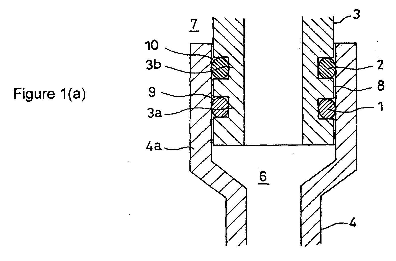
- Figure 1(a) shows a seal structure of the invention
employed as a shaft seal, and Figure 1(b) shows the two
seal members employed in Figure 1(a);
- Figure 2 is a main part expanded view of the seal
structure shown in Figure 1(a).
- Figure 3 shows a different embodiment mode to that of
Figure 1, Figure 3(a) shows a seal structure of the
invention employed as the flat surface seal, and Figure
3(b) shows the two seal members employed in Figure
3 (a).
-
-
A description of a first example of an embodiment
of the seal structure pertaining to the invention is
given below with reference to the diagrams. It should
be noted that the description given below pertains to
the employment of 0-rings as the seal members 1 and 2.
-
The embodiment shown in Figure 1 and Figure 2, in
which the seal structure pertaining to the invention is
employed for pipe connection between devices (not shown
in the diagram) from which a refrigeration cycle in
which a C02 refrigerant is employed is configured,
provides an illustration of a shaft seal employed for
preventing leak of a C02 refrigerant along the shaft
direction of seal members 1 and 2 into a space 7 on the
exterior air side by the interposing thereof in the
section of connection of an open end part of one pipe 3
and an open end part of another pipe 4.
-
The abovementioned seal structure in this
embodiment mode is one in which, as shown in Figure 1
(a), two small diameter parts 3a, 3b are formed by the
reduction of the diameter in the open end part of the
first pipe 3, seal members 1, 2 are exterior fitted
into these small diameter parts 3a, 3b, and a large
diameter part 4a is formed by the enlarging of the
diameter in the open end part of the other pipe 4.
-
In addition, by the exterior fitting in such a way
that the seal members 1, 2 and the open end part of the
pipe 3 are covered by the large diameter part 4a, the
seal members 1, 2 are caused to fit between the small
diameter part 3a and small diameter part 3b of the pipe
3 and the large diameter part 4a of the pipe 4
whereupon, by the resultant compression of the seal
members 1, 2 are compressed along the diametrical
direction of said seal members 1, 2 and the utilization
of the restoring force of the seal members 1, 2, a seal
is formed between the two pipes 3, 4.
-
Incidentally, the seal member 1, which as shown in
Figure 2 is arranged in the side of the seal structure
that inter-connects with a flow passage 6 for the C02
refrigerant, is formed from a material that prevents
the permeation of the C02 refrigerant. More
specifically, the material employed for said purpose is
a material with a small permeability coefficient with
respect to the C02 refrigerant gas such as a butyl
(IIR) based material or ethylene (ACM) based material.
-
In contrast therewith, the seal member 2, which as
shown in Figure 2 is arranged in the side of the seal
structure that inter-connects with the space 7 of the
exterior air side, is formed from, for example, a
material of excellent cold resistance that, even in
cold temperatures of minus 30°C, neither hardens nor
loses elasticity. More specifically, a hydrogenated
nitrile (HNBR) based material, fluorine (FKM) based
material or ethylene propylene (EPDM) based material or
the like is employed.
-
In addition, by virtue of the fact that the seal
member 1 and seal member 2 do not use the equal small
diameter parts and are exterior fitted separately into
different small diameter parts 3a, 3b, where the seal
members 1, 2 are fitted between the small diameter part
3a and small diameter part 3b of the pipe 3 and the
large diameter part 4a of the pipe 4 as described
above, as shown in, in particular, Figure 2, two
annular chambers 9, 10 inter-connected only by a small
gap 8 between the seal members 1 and 2 are defined.
-
Because, based on a configuration such as this,
the seal member 2 demonstrates the desired sealing
characteristics even at times of low external
temperature, there is no dramatic increase in the
quantity of leak even if the seal member 1 hardens. In
addition, the undesirable twist and warp caused by the
blow-by of the refrigerant can be avoided. Furthermore,
because the refrigerant pressure is comparatively low
at times of low external temperature, the leak can be
maintained at a level less than the desired quantity of
leak using the seal member 2.
-
Based on the description given above, although the
seal member 1 is comparatively inferior in terms of
cold resistance at no time, because a seal member 2 of
a characteristic cold resistance is interposed between
the exterior air side, is it exposed to the exterior
air. For this reason, even a loss of elasticity of the
seal member 1 caused by low temperature occurs, the
leak of a large quantity of refrigerant can be avoided.
Simultaneously, the blow-by of a large quantity of
refrigerant due to the pressure difference between the
exterior air and refrigerant, and an increase in the
quantity of leak during recovery to normal temperature
caused by the generation of twist and warp in the seal
members 1 and 2 due to shock when blow-by occurs can be
avoided.
-
In contrast thereto, Figure 3 shows another
embodiment mode of the seal structure, and this seal
illustrates a structure for a flat surface seal
structure for preventing leak of liquid in the
diametrical direction with respect to the seal members
1, 2. It should be noted that for elements of the
configuration the same as the previous embodiment
identical symbols have been assigned and the
description thereof has been omitted.
-
In this embodiment mode, annular grooves 13, 14
into which the seal members 1, 2 are fitted are formed
in a pair in the perimeter of an open section 12 in the
end surface 11a of a first member 11 in such a way as
to form a concentric circle with respect to the center
of the abovementioned open section 12, the seal members
1, 2 are fitted by the two members 11, 15 by the
pressing of the end surface 11a of a first member 11
and the end surface 15a of an opposing other member 15
together in such a way as to cover the seal members 1,
2 sandwiched between the annular grooves 13, 14 and the
open section 12 whereby, as a result, by the
compression of the seal members 1, 2 along the shaft
direction of the said seal members 1, 2 and the
utilization of the restoring force of the seal members
1, 2, the space between the two members 11, 15 is
sealed.
-
However, in this embodiment mode, the seal member
1 of small permeability coefficient with respect to a
C02 refrigerant is arranged in an annular chamber 9
defined by the annular groove 13 and end surface 15a
formed at the side that has inter-connection with the
refrigerant fluid passage, and the seal member 2 of
excellent cold resistance is arranged in an annular
chamber 10 defined by the annular groove 14 and end
surface 15a formed at the side that has inter-connection
with the space 7 on the exterior air side.
-
Based on a configuration such as this, because the
desired seal characteristics are demonstrated by the
seal member 2 even at times of low external
temperature, even if the seal member hardens no
dramatic increase in the quantity of leak occurs. In
addition, the undesirable twist and warp caused by
blow-by of the refrigerant can be avoided. Furthermore,
at times of comparatively low refrigerant pressure, the
quantity of leak can be maintained below the desired
quantity using the seal member 2.
-
Furthermore, in this embodiment mode, although the
seal member 1 has relatively inferior cold resistance,
by virtue of the fact that, the seal member 2 of
characteristic cold resistance is interposed between
the atmospheric side, the exposure thereof to exterior
air is constantly prevented. For this reason, even if a
loss of elasticity of the seal member 1 occurs the leak
of a large quantity of refrigerant can be avoided.
Simultaneously, the blow-by of a large quantity of
refrigerant due to the pressure difference between the
exterior air and refrigerant, and an increase in the
quantity of leak during recovery to normal temperature
caused by the generation of twist and warp in the seal
members 1, 2 due to shock when blow-by occurs can be
avoided.
-
It should be noted that, although the description
given in these two embodiment modes is of cases in
which one seal member 1 with permeability resistance to
a C02 refrigerant and one seal member with cold
resistance are employed, the invention is not necessarily
limited thereto and, although not shown in the diagrams,
a plurality of each may be arranged as appropriate.