EP1544482B1 - Schraube für den Einsatz bei Fenster- oder Türprofilen - Google Patents
Schraube für den Einsatz bei Fenster- oder Türprofilen Download PDFInfo
- Publication number
- EP1544482B1 EP1544482B1 EP04106493A EP04106493A EP1544482B1 EP 1544482 B1 EP1544482 B1 EP 1544482B1 EP 04106493 A EP04106493 A EP 04106493A EP 04106493 A EP04106493 A EP 04106493A EP 1544482 B1 EP1544482 B1 EP 1544482B1
- Authority
- EP
- European Patent Office
- Prior art keywords
- screw
- thread
- approximately
- diameter
- window
- Prior art date
- Legal status (The legal status is an assumption and is not a legal conclusion. Google has not performed a legal analysis and makes no representation as to the accuracy of the status listed.)
- Expired - Lifetime
Links
Images
Classifications
-
- F—MECHANICAL ENGINEERING; LIGHTING; HEATING; WEAPONS; BLASTING
- F16—ENGINEERING ELEMENTS AND UNITS; GENERAL MEASURES FOR PRODUCING AND MAINTAINING EFFECTIVE FUNCTIONING OF MACHINES OR INSTALLATIONS; THERMAL INSULATION IN GENERAL
- F16B—DEVICES FOR FASTENING OR SECURING CONSTRUCTIONAL ELEMENTS OR MACHINE PARTS TOGETHER, e.g. NAILS, BOLTS, CIRCLIPS, CLAMPS, CLIPS OR WEDGES; JOINTS OR JOINTING
- F16B25/00—Screws that cut thread in the body into which they are screwed, e.g. wood screws
- F16B25/10—Screws performing an additional function to thread-forming, e.g. drill screws or self-piercing screws
- F16B25/103—Screws performing an additional function to thread-forming, e.g. drill screws or self-piercing screws by means of a drilling screw-point, i.e. with a cutting and material removing action
-
- F—MECHANICAL ENGINEERING; LIGHTING; HEATING; WEAPONS; BLASTING
- F16—ENGINEERING ELEMENTS AND UNITS; GENERAL MEASURES FOR PRODUCING AND MAINTAINING EFFECTIVE FUNCTIONING OF MACHINES OR INSTALLATIONS; THERMAL INSULATION IN GENERAL
- F16B—DEVICES FOR FASTENING OR SECURING CONSTRUCTIONAL ELEMENTS OR MACHINE PARTS TOGETHER, e.g. NAILS, BOLTS, CIRCLIPS, CLAMPS, CLIPS OR WEDGES; JOINTS OR JOINTING
- F16B25/00—Screws that cut thread in the body into which they are screwed, e.g. wood screws
- F16B25/001—Screws that cut thread in the body into which they are screwed, e.g. wood screws characterised by the material of the body into which the screw is screwed
- F16B25/0021—Screws that cut thread in the body into which they are screwed, e.g. wood screws characterised by the material of the body into which the screw is screwed the material being metal, e.g. sheet-metal or aluminium
-
- F—MECHANICAL ENGINEERING; LIGHTING; HEATING; WEAPONS; BLASTING
- F16—ENGINEERING ELEMENTS AND UNITS; GENERAL MEASURES FOR PRODUCING AND MAINTAINING EFFECTIVE FUNCTIONING OF MACHINES OR INSTALLATIONS; THERMAL INSULATION IN GENERAL
- F16B—DEVICES FOR FASTENING OR SECURING CONSTRUCTIONAL ELEMENTS OR MACHINE PARTS TOGETHER, e.g. NAILS, BOLTS, CIRCLIPS, CLAMPS, CLIPS OR WEDGES; JOINTS OR JOINTING
- F16B35/00—Screw-bolts; Stay-bolts; Screw-threaded studs; Screws; Set screws
- F16B35/04—Screw-bolts; Stay-bolts; Screw-threaded studs; Screws; Set screws with specially-shaped head or shaft in order to fix the bolt on or in an object
-
- E—FIXED CONSTRUCTIONS
- E05—LOCKS; KEYS; WINDOW OR DOOR FITTINGS; SAFES
- E05D—HINGES OR SUSPENSION DEVICES FOR DOORS, WINDOWS OR WINGS
- E05D5/00—Construction of single parts, e.g. the parts for attachment
- E05D5/02—Parts for attachment, e.g. flaps
- E05D5/0215—Parts for attachment, e.g. flaps for attachment to profile members or the like
- E05D5/0223—Parts for attachment, e.g. flaps for attachment to profile members or the like with parts, e.g. screws, extending through the profile wall or engaging profile grooves
- E05D5/023—Parts for attachment, e.g. flaps for attachment to profile members or the like with parts, e.g. screws, extending through the profile wall or engaging profile grooves with parts extending through the profile wall
-
- E—FIXED CONSTRUCTIONS
- E05—LOCKS; KEYS; WINDOW OR DOOR FITTINGS; SAFES
- E05Y—INDEXING SCHEME ASSOCIATED WITH SUBCLASSES E05D AND E05F, RELATING TO CONSTRUCTION ELEMENTS, ELECTRIC CONTROL, POWER SUPPLY, POWER SIGNAL OR TRANSMISSION, USER INTERFACES, MOUNTING OR COUPLING, DETAILS, ACCESSORIES, AUXILIARY OPERATIONS NOT OTHERWISE PROVIDED FOR, APPLICATION THEREOF
- E05Y2800/00—Details, accessories and auxiliary operations not otherwise provided for
- E05Y2800/67—Materials; Strength alteration thereof
- E05Y2800/676—Plastics
-
- E—FIXED CONSTRUCTIONS
- E05—LOCKS; KEYS; WINDOW OR DOOR FITTINGS; SAFES
- E05Y—INDEXING SCHEME ASSOCIATED WITH SUBCLASSES E05D AND E05F, RELATING TO CONSTRUCTION ELEMENTS, ELECTRIC CONTROL, POWER SUPPLY, POWER SIGNAL OR TRANSMISSION, USER INTERFACES, MOUNTING OR COUPLING, DETAILS, ACCESSORIES, AUXILIARY OPERATIONS NOT OTHERWISE PROVIDED FOR, APPLICATION THEREOF
- E05Y2800/00—Details, accessories and auxiliary operations not otherwise provided for
- E05Y2800/67—Materials; Strength alteration thereof
- E05Y2800/682—Strength alteration by reinforcing, e.g. by applying ribs
-
- E—FIXED CONSTRUCTIONS
- E05—LOCKS; KEYS; WINDOW OR DOOR FITTINGS; SAFES
- E05Y—INDEXING SCHEME ASSOCIATED WITH SUBCLASSES E05D AND E05F, RELATING TO CONSTRUCTION ELEMENTS, ELECTRIC CONTROL, POWER SUPPLY, POWER SIGNAL OR TRANSMISSION, USER INTERFACES, MOUNTING OR COUPLING, DETAILS, ACCESSORIES, AUXILIARY OPERATIONS NOT OTHERWISE PROVIDED FOR, APPLICATION THEREOF
- E05Y2900/00—Application of doors, windows, wings or fittings thereof
- E05Y2900/10—Application of doors, windows, wings or fittings thereof for buildings or parts thereof
- E05Y2900/13—Type of wing
- E05Y2900/132—Doors
-
- E—FIXED CONSTRUCTIONS
- E05—LOCKS; KEYS; WINDOW OR DOOR FITTINGS; SAFES
- E05Y—INDEXING SCHEME ASSOCIATED WITH SUBCLASSES E05D AND E05F, RELATING TO CONSTRUCTION ELEMENTS, ELECTRIC CONTROL, POWER SUPPLY, POWER SIGNAL OR TRANSMISSION, USER INTERFACES, MOUNTING OR COUPLING, DETAILS, ACCESSORIES, AUXILIARY OPERATIONS NOT OTHERWISE PROVIDED FOR, APPLICATION THEREOF
- E05Y2900/00—Application of doors, windows, wings or fittings thereof
- E05Y2900/10—Application of doors, windows, wings or fittings thereof for buildings or parts thereof
- E05Y2900/13—Type of wing
- E05Y2900/148—Windows
-
- E—FIXED CONSTRUCTIONS
- E06—DOORS, WINDOWS, SHUTTERS, OR ROLLER BLINDS IN GENERAL; LADDERS
- E06B—FIXED OR MOVABLE CLOSURES FOR OPENINGS IN BUILDINGS, VEHICLES, FENCES OR LIKE ENCLOSURES IN GENERAL, e.g. DOORS, WINDOWS, BLINDS, GATES
- E06B3/00—Window sashes, door leaves, or like elements for closing wall or like openings; Layout of fixed or moving closures, e.g. windows in wall or like openings; Features of rigidly-mounted outer frames relating to the mounting of wing frames
- E06B3/04—Wing frames not characterised by the manner of movement
- E06B3/06—Single frames
- E06B3/08—Constructions depending on the use of specified materials
- E06B3/20—Constructions depending on the use of specified materials of plastics
- E06B3/22—Hollow frames
- E06B3/221—Hollow frames with the frame member having local reinforcements in some parts of its cross-section or with a filled cavity
- E06B3/222—Hollow frames with the frame member having local reinforcements in some parts of its cross-section or with a filled cavity with internal prefabricated reinforcing section members inserted after manufacturing of the hollow frame
Definitions
- the invention relates to a screw for use in window or door profiles, consisting of a threaded shaft, a drill bit and a head equipped with a tool attack.
- Such a screw is from the document DE-U-94 05 595 known.
- the present invention has therefore set itself the task of creating a screw of the type mentioned, covering a large part of all applications in window or door profiles.
- the screw has a metric thread with a ratio of diameter to thread pitch of approximately 4: 1.
- a metric thread with a diameter of approximately 3.9 mm and a thread pitch of approximately 1.0 mm is provided. This is a preferred embodiment which provides optimum performance in most window screw or door profile applications.
- the ratio of diameter of the screw and length of the drill bit is approximately 1: 2. It is precisely this configuration that it comes to virtually no failures when using the screws in screwdrivers. It is thus quite possible to use such screws with a structure as follows: 3 mm PVC / 10 mm air gap / 1.2 mm PVC / 1.5 mm steel.
- a further advantageous embodiment provides that the screw is designed as a countersunk screw. It is thus also a depression of the head in the actually always outside plastic wall of a profile possible, with no Ansenkrippen or other cutting elements are required.
- the top of the screw head is formed lens-shaped convex and provided with an internal attack and / or an attack slot. It is thereby given an aesthetically optimal conclusion, although the required insertion torque can be transferred well.
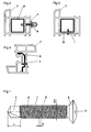
- the enlarged in Fig. 1 illustrated screw 1 is intended for use in window or door profiles.
- the screw 1 consists of a provided with a thread 2 shank 3, a drill bit 4 and equipped with a tool attack 5 head 6.
- the screw has a metric thread 2 with a ratio of diameter DA to thread pitch S of approximately 4: 1.
- the metric thread 2 is designed with a diameter DA of approximately 3.9 mm and a thread pitch S of approximately 1.0 mm.
- the ratio of diameter DA of the screw 1 and length L of the drill bit is approximately 1: 2.
- a concrete embodiment provides to use a metric thread 2, which has an outer diameter DA of 3.9 mm and a thread pitch S of 1.0 mm.
- the length L of the drill bit in this embodiment is 7.0 mm.
- the stated ratios between diameter DA and thread pitch S and the length L of the drill bit 4 can of course change in a corresponding frame and are therefore essentially accurate for screws of the diameter size of 3.9 or 4.0 mm.
- the similar values are to be observed even with screws of larger diameter, but usually just in the window or door profile area screws are always used with an outer diameter DA of about 3.9 to 4.0 mm.
- An expedient embodiment also provides for the thread 2 to be left immediately adjacent to the drill bit and to be guided over the entire length of the shank 3 of the screw 1.
- the screw 1 may be formed as a countersunk screw. As a rule, this can be a smooth truncated cone. However, it would also be conceivable to arrange here milling ribs, if only by a proper countersinking is possible.
- the top of the screw head 6 is advantageously formed lens-shaped convex and provided with an internal attack and / or an attack slot 5.
- FIGS. 2 to 4 show different variants of plastic profiles 7 and metal profiles 8 as well as fittings 9 to be fastened, which are mutually connected to the screws 1 according to the invention.
- this represents only a small selection of possible uses of the inventive screw 1.
Landscapes
- Engineering & Computer Science (AREA)
- General Engineering & Computer Science (AREA)
- Mechanical Engineering (AREA)
- Connection Of Plates (AREA)
- Securing Of Glass Panes Or The Like (AREA)
Description
- Die Erfindung betrifft eine Schraube für den Einsatz bei Fenster- oder Türprofilen, bestehend aus einem mit einem Gewinde versehenen Schaft, einer Bohrspitze und einem mit einem Werkzeugangriff ausgestatteten Kopf.
- Eine solche Schraube ist aus dem Dokument
DE-U-94 05 595 bekannt. - Bei der Montage im Bereich von Fenster- oder Türprofilen werden zur gegenseitigen Verbindung von Profilen oder zur Befestigung von Beschlägen usw. eine Reihe von Schrauben benötigt. Es wurden dabei für die verschiedenen Einsatzzwecke in den Bereich von Kunststoffprofilen oder in den Bereich mit eingesetzten Metallprofilen oder -beschlägen auch entsprechend verschiedene Schrauben mit einem Blechgewinde (in der Regel mit einem Gewindeaussendurchmesser von 3,9 mm) oder mit einem metrischen Gewinde (in der Regel mit einem M4-Gewinde) benötigt. Daher waren auch die Lagerhaltung für die Vielzahl verschiedener Schrauben und auch die Fertigungskosten entsprechend hoch.
- Die vorliegende Erfindung hat sich daher zur Aufgabe gestellt, eine Schraube der eingangs genannten Art zu schaffen, die einen Grossteil aller Einsatzgebiete bei Fenster- oder Türprofilen abdeckt.
- Dies gelingt erfindungsgemäss dadurch, dass die Schraube ein metrisches Gewinde mit einem Verhältnis von Durchmesser zu Gewindesteigung von annähernd 4:1 aufweist.
- Bei einem rein metrischen Gewinde (bei annähernd M4) ist dieses Verhältnis annähernd 5,7:1 und bei einem reinen Blechschraubengewinde (mit Aussendurchmesser 3,9 mm) ist dieses Verhältnis annähernd 3:1. Mit dem erfindungsgemäss nun vorgeschlagenen, an sich metrischen Gewinde, welches jedoch eine andere Gewindesteigung hat als ein übliches metrisches Gewinde ist eine Möglichkeit geschaffen worden, dass eine Type von Schrauben für fast alle Anwendungen im Fenster- und Türenbau eingesetzt werden kann.
- Ferner wird vorgeschlagen, dass ein metrisches Gewinde mit einem Durchmesser von annähernd 3,9 mm und einer Gewindesteigung von annähernd 1,0 mm vorgesehen ist. Dies ist eine bevorzugte Ausführungsvariante, die eine optimale Leistung in den meisten Einsatzfällen von Schrauben bei Fenster- oder Türprofilen mit sich bringt.
- Im Rahmen der Erfindung ist es auch vorteilhaft, wenn das Verhältnis von Durchmesser der Schraube und Länge der Bohrspitze annähernd 1:2 beträgt. Gerade diese Ausgestaltung bringt es mit sich, dass es praktisch zu keinen Ausfällen beim Einsatz der Schrauben in Schraubautomaten kommt. Es ist also durchaus ohne Probleme möglich, solche Schrauben einzusetzen bei einem Aufbau wie folgt: 3 mm PVC /10 mm Luftspalt /1,2 mm PVC /1,5 mm Stahl.
- In diesem Zusammenhang ist eine besondere Variante darin zu sehen, wenn ein metrisches Gewinde mit einem Aussendurchmesser von 3,9 mm und einer Gewindesteigung von 1,0 mm vorgesehen ist und die Länge der Bohrspitze 7,0 mm beträgt. Mit einer solchen Schraube können ohne weiteres Bohrleistungen im Stahl von 1 bis 3 mm erzielt werden.
- Eine weitere vorteilhafte Ausgestaltung sieht vor, dass die Schraube als Senkkopfschraube ausgebildet ist. Es ist damit auch eine Einsenkung des Kopfes in dem eigentlich immer aussen liegenden Kunststoffwandung eines Profils möglich, wobei keine Ansenkrippen oder andere Fräselemente erforderlich sind.
- In diesem Zusammenhang ist es auch zweckmässig, wenn die Oberseite des Schraubenkopfes linsenförmig konvex ausgebildet und mit einem Innenangriff und/oder einem Angriffsschlitz versehen ist. Es ist dadurch ein ästhetisch optimaler Abschluss gegeben, obwohl das erforderliche Eindrehmoment gut übertragen werden kann.
- Weitere erfindungsgemässe Merkmale und besondere Vorteile werden in der nachstehenden Beschreibung anhand der Zeichnung noch näher erläutert. Es zeigen:
- Fig. 1 eine erfindungsgemässe Schraube in Seitenansicht;
- die Fig. 2 bis 4 verschiedene Varianten von Fenster- oder Türprofilen, bei welchen eine erfindungsgemässe Schraube zum Einsatz kommt.
- Die in Fig. 1 vergrössert dargestellte Schraube 1 ist für den Einsatz bei Fenster- oder Türprofilen vorgesehen. Die Schraube 1 besteht aus einem mit einem Gewinde 2 versehenen Schaft 3, einer Bohrspitze 4 und einem mit einem Werkzeugangriff 5 ausgestatteten Kopf 6. Die Schraube weist ein metrisches Gewinde 2 mit einem Verhältnis von Durchmesser DA zu Gewindesteigung S von annähernd 4:1 auf. Das metrisches Gewinde 2 ist mit einem Durchmesser DA von annähernd 3,9 mm und einer Gewindesteigung S von annähernd 1,0 mm ausgeführt.
- Das Verhältnis von Durchmesser DA der Schraube 1 und Länge L der Bohrspitze beträgt annähernd 1:2. Eine konkrete Ausführung sieht vor, ein metrisches Gewinde 2 einzusetzen, welches einen Aussendurchmesser DA von 3,9 mm und einer Gewindesteigung S von 1,0 mm aufweist. Die Länge L der Bohrspitze beträgt bei dieser Ausführungsvariante 7,0 mm.
- Die angeführten Verhältnisse zwischen Durchmesser DA und Gewindesteigung S sowie der Länge L der Bohrspitze 4 können sich natürlich in entsprechendem Rahmen ändern und sind daher im Wesentlichen für Schrauben der Durchmessergrösse um 3,9 oder 4.0 mm exakt zutreffend. Die an sich ähnlichen Werte sind auch bei Schrauben grösseren Durchmessers einzuhalten, wobei aber in der Regel gerade im Fenster- oder Türprofilbereich immer Schrauben mit einem Aussendurchmesser DA von etwa 3,9 bis 4.0 mm eingesetzt werden.
- Eine zweckmässige Ausgestaltung sieht noch vor, das Gewinde 2 unmittelbar an die Bohrspitze anschliessend beginn zu lassen und über die ganze Länge des Schaftes 3 der Schraube 1 zu führen.
- Die Schraube 1 kann als Senkkopfschraube ausgebildet sein. In der Regel kann dies ein glatter Kegelstumpf sein. Es wäre aber auch denkbar, hier Fräsrippen anzuordnen, falls nur dadurch ein ordnungsgemässes Versenken möglich ist.
- Die Oberseite des Schraubenkopfes 6 ist vorteilhaft linsenförmig konvex ausgebildet und mit einem Innenangriff und/oder einem Angriffsschlitz 5 versehen.
- Aufgrund der erfindungsgemässen Massnahmen kann nicht nur eine optimale Bohrund Setzleistung auf fast allen Einsatzbereichen bei Fenster- oder Türprofilen erreicht werden, sondern es ergibt sich daraus auch die Möglichkeit einer Sortimentsbereinigung bei den einzusetzenden Schrauben, was zusätzlich zu einer Minimierung der Kosten führt.
- In den Fig. 2 bis 4 sind verschiedene Ausführungsvarianten von Kunststoffprofilen 7 und Metallprofilen 8 sowie von zu befestigenden Beschlägen 9 gezeigt, welche mit den erfindungsgemässen Schrauben 1 gegenseitig verbunden werden. Dies stellt natürlich nur eine kleine Auswahl der Einsatzmöglichkeiten der erfindungsgemässen Schraube 1 dar.
Claims (6)
- Schraube für den Einsatz bei Fenster- oder Türprofilen, bestehend aus einem mit einem Gewinde versehenen Schaft, einer Bohrspitze und einem mit einem Werkzeugangriff ausgestatteten Kopf, dadurch gekennzeichnet, dass die Schraube (1) ein metrisches Gewinde (2) mit einem Verhältnis von Durchmesser (DA) zu Gewindesteigung (S) von annähernd 4:1 aufweist.
- Schraube nach Anspruch 1, dadurch gekennzeichnet, dass ein metrisches Gewinde (2) mit einem Durchmesser (DA) von annähernd 3,9 mm und einer Gewindesteigung (S) von annähernd 1,0 mm vorgesehen ist.
- Schraube nach Anspruch 1, dadurch gekennzeichnet, dass das Verhältnis von Durchmesser (DA) der Schraube (1) und Länge (L) der Bohrspitze (4) annähernd 1:2 beträgt.
- Schraube nach den Ansprüchen 1 bis 3, dadurch gekennzeichnet, dass ein metrisches Gewinde (2) mit einem Aussendurchmesser (DA) von 3,9 mm und einer Gewindesteigung (S) von 1,0 mm vorgesehen ist und die Länge (L) der Bohrspitze (4) 7,0 mm beträgt.
- Schraube nach Anspruch 1 und einem der vorstehenden Ansprüche, dadurch gekennzeichnet, dass diese als Senkkopfschraube ausgebildet ist.
- Schraube nach Anspruch 5, dadurch gekennzeichnet, dass die Oberseite des Schraubenkopfes (6) linsenförmig konvex ausgebildet und mit einem Innenangriff und/oder einem Angriffsschlitz (5) versehen ist.
Applications Claiming Priority (2)
| Application Number | Priority Date | Filing Date | Title |
|---|---|---|---|
| DE20319690U DE20319690U1 (de) | 2003-12-18 | 2003-12-18 | Schraube für den Einsatz bei Fenster- oder Türprofilen |
| DE20319690U | 2003-12-18 |
Publications (2)
| Publication Number | Publication Date |
|---|---|
| EP1544482A1 EP1544482A1 (de) | 2005-06-22 |
| EP1544482B1 true EP1544482B1 (de) | 2008-01-02 |
Family
ID=34485649
Family Applications (1)
| Application Number | Title | Priority Date | Filing Date |
|---|---|---|---|
| EP04106493A Expired - Lifetime EP1544482B1 (de) | 2003-12-18 | 2004-12-13 | Schraube für den Einsatz bei Fenster- oder Türprofilen |
Country Status (3)
| Country | Link |
|---|---|
| EP (1) | EP1544482B1 (de) |
| AT (1) | ATE382797T1 (de) |
| DE (2) | DE20319690U1 (de) |
Families Citing this family (2)
| Publication number | Priority date | Publication date | Assignee | Title |
|---|---|---|---|---|
| GB201102207D0 (en) * | 2011-02-09 | 2011-03-23 | Window Widgets Llp | Improvements in or relating to windows |
| WO2018176437A1 (zh) * | 2017-04-01 | 2018-10-04 | 华健 | 螺栓以及与其配合专用的套筒结构 |
Family Cites Families (4)
| Publication number | Priority date | Publication date | Assignee | Title |
|---|---|---|---|---|
| DE3337534A1 (de) * | 1983-10-14 | 1985-05-02 | Alfons 5758 Fröndenberg Knoche | Universalschraube, werkzeug zur herstellung derartiger universalschrauben, und schraubendreher fuer derartige universalschrauben |
| DE9405595U1 (de) * | 1994-04-02 | 1994-06-16 | ITW Befestigungssysteme GmbH, 58642 Iserlohn | Selbstbohrschraube für Fensterrahmen, Türrahmen o.dgl. |
| DE19637969C2 (de) * | 1996-09-18 | 2000-04-27 | Schrauben Betzer Gmbh & Co Kg | Spanlos loch- und gewindeformende Dünnblechschraube |
| DE19840298A1 (de) * | 1998-09-04 | 2000-03-16 | Ejot Verbindungstech Gmbh & Co | Selbstgewindeformende Schraube aus Leichtmetall und Verfahren zu ihrer Herstellung |
-
2003
- 2003-12-18 DE DE20319690U patent/DE20319690U1/de not_active Expired - Lifetime
-
2004
- 2004-12-13 AT AT04106493T patent/ATE382797T1/de not_active IP Right Cessation
- 2004-12-13 DE DE502004005817T patent/DE502004005817D1/de not_active Expired - Fee Related
- 2004-12-13 EP EP04106493A patent/EP1544482B1/de not_active Expired - Lifetime
Also Published As
| Publication number | Publication date |
|---|---|
| ATE382797T1 (de) | 2008-01-15 |
| EP1544482A1 (de) | 2005-06-22 |
| DE20319690U1 (de) | 2005-05-04 |
| DE502004005817D1 (de) | 2008-02-14 |
Similar Documents
| Publication | Publication Date | Title |
|---|---|---|
| EP1925828B1 (de) | Schraube | |
| EP0975877B1 (de) | Selbstbohrendes und gewindeformendes verbindungselement | |
| EP0292742B1 (de) | Distanzschraube | |
| DE1500798B1 (de) | Bohr- und Gewindeformschraube | |
| DE19615191C5 (de) | Schraube und Verfahren zur drehmomentbegrenzten Befestigung von Metall- und/oder Kunststoffprofilen oder -platten auf einem Unterbau | |
| EP3040563A1 (de) | Schraube mit diskontinuität an zwischengewindeabschnitt | |
| EP1233194B1 (de) | Betonschraube | |
| DE102014000940A1 (de) | Schraube, Befestigungsanordnung und Verwendung einer Schraube | |
| EP1990551A2 (de) | Selbstbohrende Schraube | |
| EP1544482B1 (de) | Schraube für den Einsatz bei Fenster- oder Türprofilen | |
| EP0831239B1 (de) | Schneidschraube | |
| EP3199824A1 (de) | Befestigungsanordnung und verwendung einer befestigungsanordnung | |
| EP0267153B1 (de) | Schraube zur Abstandsbefestigung von Bauteilen | |
| DE102007003518B4 (de) | Schraube, insbesondere zur Durchsteckmontage von Fensterrahmen in der Laibung eines Mauerwerks | |
| DE102010045445A1 (de) | Montagesystem für Isolierstoffplatten | |
| EP2491258B1 (de) | Bohrschraube | |
| EP3097314A1 (de) | Verfahren zum herstellen einer befestigungsanordnung, befestigungsanordnung und dafür vorgesehene schraube | |
| EP0527999B1 (de) | Schraube zum eindrehen in sacklöcher geringer tiefe | |
| AT12726U1 (de) | Schraube für das befestigen eines holzteiles | |
| DE3043478A1 (de) | Selbstbohrende schraube | |
| DE19506081A1 (de) | Befestigungselement | |
| DE202015100333U1 (de) | Gewindeformende Schraube | |
| DE20320553U1 (de) | Einrichtung zur distanzierten Befestigung von Wärmedämmplatten an Wänden oder Decken | |
| DE2551510A1 (de) | Selbstschneidende schraube | |
| DE19837024A1 (de) | System zum Befestigen von Verankerungsteilen an der Rückseite von Fassadenplatten |
Legal Events
| Date | Code | Title | Description |
|---|---|---|---|
| PUAI | Public reference made under article 153(3) epc to a published international application that has entered the european phase |
Free format text: ORIGINAL CODE: 0009012 |
|
| AK | Designated contracting states |
Kind code of ref document: A1 Designated state(s): AT BE BG CH CY CZ DE DK EE ES FI FR GB GR HU IE IS IT LI LT LU MC NL PL PT RO SE SI SK TR |
|
| AX | Request for extension of the european patent |
Extension state: AL BA HR LV MK YU |
|
| 17P | Request for examination filed |
Effective date: 20051007 |
|
| AKX | Designation fees paid |
Designated state(s): AT BE BG CH CY CZ DE DK EE ES FI FR GB GR HU IE IS IT LI LT LU MC NL PL PT RO SE SI SK TR |
|
| GRAP | Despatch of communication of intention to grant a patent |
Free format text: ORIGINAL CODE: EPIDOSNIGR1 |
|
| GRAS | Grant fee paid |
Free format text: ORIGINAL CODE: EPIDOSNIGR3 |
|
| GRAA | (expected) grant |
Free format text: ORIGINAL CODE: 0009210 |
|
| AK | Designated contracting states |
Kind code of ref document: B1 Designated state(s): AT BE BG CH CY CZ DE DK EE ES FI FR GB GR HU IE IS IT LI LT LU MC NL PL PT RO SE SI SK TR |
|
| REG | Reference to a national code |
Ref country code: GB Ref legal event code: FG4D Free format text: NOT ENGLISH |
|
| RTI1 | Title (correction) |
Free format text: SCREW TO BE USED WITH WINDOW OR DOOR PROFILES |
|
| REG | Reference to a national code |
Ref country code: IE Ref legal event code: FG4D Free format text: LANGUAGE OF EP DOCUMENT: GERMAN |
|
| REG | Reference to a national code |
Ref country code: CH Ref legal event code: EP |
|
| REF | Corresponds to: |
Ref document number: 502004005817 Country of ref document: DE Date of ref document: 20080214 Kind code of ref document: P |
|
| PG25 | Lapsed in a contracting state [announced via postgrant information from national office to epo] |
Ref country code: NL Free format text: LAPSE BECAUSE OF FAILURE TO SUBMIT A TRANSLATION OF THE DESCRIPTION OR TO PAY THE FEE WITHIN THE PRESCRIBED TIME-LIMIT Effective date: 20080102 Ref country code: SI Free format text: LAPSE BECAUSE OF FAILURE TO SUBMIT A TRANSLATION OF THE DESCRIPTION OR TO PAY THE FEE WITHIN THE PRESCRIBED TIME-LIMIT Effective date: 20080102 |
|
| NLV1 | Nl: lapsed or annulled due to failure to fulfill the requirements of art. 29p and 29m of the patents act | ||
| GBV | Gb: ep patent (uk) treated as always having been void in accordance with gb section 77(7)/1977 [no translation filed] | ||
| PG25 | Lapsed in a contracting state [announced via postgrant information from national office to epo] |
Ref country code: LT Free format text: LAPSE BECAUSE OF FAILURE TO SUBMIT A TRANSLATION OF THE DESCRIPTION OR TO PAY THE FEE WITHIN THE PRESCRIBED TIME-LIMIT Effective date: 20080102 Ref country code: IS Free format text: LAPSE BECAUSE OF FAILURE TO SUBMIT A TRANSLATION OF THE DESCRIPTION OR TO PAY THE FEE WITHIN THE PRESCRIBED TIME-LIMIT Effective date: 20080502 Ref country code: ES Free format text: LAPSE BECAUSE OF FAILURE TO SUBMIT A TRANSLATION OF THE DESCRIPTION OR TO PAY THE FEE WITHIN THE PRESCRIBED TIME-LIMIT Effective date: 20080413 Ref country code: FI Free format text: LAPSE BECAUSE OF FAILURE TO SUBMIT A TRANSLATION OF THE DESCRIPTION OR TO PAY THE FEE WITHIN THE PRESCRIBED TIME-LIMIT Effective date: 20080102 |
|
| PG25 | Lapsed in a contracting state [announced via postgrant information from national office to epo] |
Ref country code: BG Free format text: LAPSE BECAUSE OF FAILURE TO SUBMIT A TRANSLATION OF THE DESCRIPTION OR TO PAY THE FEE WITHIN THE PRESCRIBED TIME-LIMIT Effective date: 20080402 |
|
| PG25 | Lapsed in a contracting state [announced via postgrant information from national office to epo] |
Ref country code: PT Free format text: LAPSE BECAUSE OF FAILURE TO SUBMIT A TRANSLATION OF THE DESCRIPTION OR TO PAY THE FEE WITHIN THE PRESCRIBED TIME-LIMIT Effective date: 20080602 Ref country code: PL Free format text: LAPSE BECAUSE OF FAILURE TO SUBMIT A TRANSLATION OF THE DESCRIPTION OR TO PAY THE FEE WITHIN THE PRESCRIBED TIME-LIMIT Effective date: 20080102 |
|
| REG | Reference to a national code |
Ref country code: IE Ref legal event code: FD4D |
|
| EN | Fr: translation not filed | ||
| PG25 | Lapsed in a contracting state [announced via postgrant information from national office to epo] |
Ref country code: CZ Free format text: LAPSE BECAUSE OF FAILURE TO SUBMIT A TRANSLATION OF THE DESCRIPTION OR TO PAY THE FEE WITHIN THE PRESCRIBED TIME-LIMIT Effective date: 20080102 Ref country code: SE Free format text: LAPSE BECAUSE OF FAILURE TO SUBMIT A TRANSLATION OF THE DESCRIPTION OR TO PAY THE FEE WITHIN THE PRESCRIBED TIME-LIMIT Effective date: 20080402 Ref country code: IE Free format text: LAPSE BECAUSE OF FAILURE TO SUBMIT A TRANSLATION OF THE DESCRIPTION OR TO PAY THE FEE WITHIN THE PRESCRIBED TIME-LIMIT Effective date: 20080102 Ref country code: DK Free format text: LAPSE BECAUSE OF FAILURE TO SUBMIT A TRANSLATION OF THE DESCRIPTION OR TO PAY THE FEE WITHIN THE PRESCRIBED TIME-LIMIT Effective date: 20080102 Ref country code: SK Free format text: LAPSE BECAUSE OF FAILURE TO SUBMIT A TRANSLATION OF THE DESCRIPTION OR TO PAY THE FEE WITHIN THE PRESCRIBED TIME-LIMIT Effective date: 20080102 |
|
| PLBE | No opposition filed within time limit |
Free format text: ORIGINAL CODE: 0009261 |
|
| STAA | Information on the status of an ep patent application or granted ep patent |
Free format text: STATUS: NO OPPOSITION FILED WITHIN TIME LIMIT |
|
| PG25 | Lapsed in a contracting state [announced via postgrant information from national office to epo] |
Ref country code: RO Free format text: LAPSE BECAUSE OF FAILURE TO SUBMIT A TRANSLATION OF THE DESCRIPTION OR TO PAY THE FEE WITHIN THE PRESCRIBED TIME-LIMIT Effective date: 20080102 |
|
| 26N | No opposition filed |
Effective date: 20081003 |
|
| PG25 | Lapsed in a contracting state [announced via postgrant information from national office to epo] |
Ref country code: GB Free format text: LAPSE BECAUSE OF FAILURE TO SUBMIT A TRANSLATION OF THE DESCRIPTION OR TO PAY THE FEE WITHIN THE PRESCRIBED TIME-LIMIT Effective date: 20080102 |
|
| PG25 | Lapsed in a contracting state [announced via postgrant information from national office to epo] |
Ref country code: FR Free format text: LAPSE BECAUSE OF FAILURE TO SUBMIT A TRANSLATION OF THE DESCRIPTION OR TO PAY THE FEE WITHIN THE PRESCRIBED TIME-LIMIT Effective date: 20081024 Ref country code: EE Free format text: LAPSE BECAUSE OF FAILURE TO SUBMIT A TRANSLATION OF THE DESCRIPTION OR TO PAY THE FEE WITHIN THE PRESCRIBED TIME-LIMIT Effective date: 20080102 |
|
| BERE | Be: lapsed |
Owner name: SFS INTEC HOLDING A.G. Effective date: 20081231 |
|
| PG25 | Lapsed in a contracting state [announced via postgrant information from national office to epo] |
Ref country code: MC Free format text: LAPSE BECAUSE OF NON-PAYMENT OF DUE FEES Effective date: 20081231 Ref country code: CY Free format text: LAPSE BECAUSE OF FAILURE TO SUBMIT A TRANSLATION OF THE DESCRIPTION OR TO PAY THE FEE WITHIN THE PRESCRIBED TIME-LIMIT Effective date: 20080102 |
|
| REG | Reference to a national code |
Ref country code: CH Ref legal event code: PL |
|
| PG25 | Lapsed in a contracting state [announced via postgrant information from national office to epo] |
Ref country code: IT Free format text: LAPSE BECAUSE OF FAILURE TO SUBMIT A TRANSLATION OF THE DESCRIPTION OR TO PAY THE FEE WITHIN THE PRESCRIBED TIME-LIMIT Effective date: 20080102 |
|
| PG25 | Lapsed in a contracting state [announced via postgrant information from national office to epo] |
Ref country code: BE Free format text: LAPSE BECAUSE OF NON-PAYMENT OF DUE FEES Effective date: 20081231 |
|
| PG25 | Lapsed in a contracting state [announced via postgrant information from national office to epo] |
Ref country code: CH Free format text: LAPSE BECAUSE OF NON-PAYMENT OF DUE FEES Effective date: 20081231 Ref country code: LI Free format text: LAPSE BECAUSE OF NON-PAYMENT OF DUE FEES Effective date: 20081231 Ref country code: DE Free format text: LAPSE BECAUSE OF NON-PAYMENT OF DUE FEES Effective date: 20090701 |
|
| PG25 | Lapsed in a contracting state [announced via postgrant information from national office to epo] |
Ref country code: AT Free format text: LAPSE BECAUSE OF NON-PAYMENT OF DUE FEES Effective date: 20081213 |
|
| PG25 | Lapsed in a contracting state [announced via postgrant information from national office to epo] |
Ref country code: LU Free format text: LAPSE BECAUSE OF NON-PAYMENT OF DUE FEES Effective date: 20081213 Ref country code: HU Free format text: LAPSE BECAUSE OF FAILURE TO SUBMIT A TRANSLATION OF THE DESCRIPTION OR TO PAY THE FEE WITHIN THE PRESCRIBED TIME-LIMIT Effective date: 20080703 |
|
| PG25 | Lapsed in a contracting state [announced via postgrant information from national office to epo] |
Ref country code: TR Free format text: LAPSE BECAUSE OF FAILURE TO SUBMIT A TRANSLATION OF THE DESCRIPTION OR TO PAY THE FEE WITHIN THE PRESCRIBED TIME-LIMIT Effective date: 20080102 |
|
| PG25 | Lapsed in a contracting state [announced via postgrant information from national office to epo] |
Ref country code: GR Free format text: LAPSE BECAUSE OF FAILURE TO SUBMIT A TRANSLATION OF THE DESCRIPTION OR TO PAY THE FEE WITHIN THE PRESCRIBED TIME-LIMIT Effective date: 20080403 |