EP1544444B1 - Method of controlling the ignition angle of an internal combustion engine - Google Patents
Method of controlling the ignition angle of an internal combustion engine Download PDFInfo
- Publication number
- EP1544444B1 EP1544444B1 EP04105671A EP04105671A EP1544444B1 EP 1544444 B1 EP1544444 B1 EP 1544444B1 EP 04105671 A EP04105671 A EP 04105671A EP 04105671 A EP04105671 A EP 04105671A EP 1544444 B1 EP1544444 B1 EP 1544444B1
- Authority
- EP
- European Patent Office
- Prior art keywords
- ignition
- internal combustion
- combustion engine
- time range
- predetermined time
- Prior art date
- Legal status (The legal status is an assumption and is not a legal conclusion. Google has not performed a legal analysis and makes no representation as to the accuracy of the status listed.)
- Expired - Lifetime
Links
- 238000002485 combustion reaction Methods 0.000 title claims description 30
- 238000000034 method Methods 0.000 title claims description 20
- 239000000203 mixture Substances 0.000 claims description 20
- 239000000446 fuel Substances 0.000 claims description 14
- 230000001960 triggered effect Effects 0.000 claims description 10
- 238000002347 injection Methods 0.000 claims description 4
- 239000007924 injection Substances 0.000 claims description 4
- 238000009841 combustion method Methods 0.000 claims description 3
- 230000001419 dependent effect Effects 0.000 claims description 3
- 238000001514 detection method Methods 0.000 description 2
- 230000032683 aging Effects 0.000 description 1
- 230000007812 deficiency Effects 0.000 description 1
- 239000006185 dispersion Substances 0.000 description 1
- 239000003344 environmental pollutant Substances 0.000 description 1
- 230000000977 initiatory effect Effects 0.000 description 1
- 238000004519 manufacturing process Methods 0.000 description 1
- 231100000719 pollutant Toxicity 0.000 description 1
- 238000002360 preparation method Methods 0.000 description 1
- 238000011084 recovery Methods 0.000 description 1
- 238000005070 sampling Methods 0.000 description 1
Images
Classifications
-
- F—MECHANICAL ENGINEERING; LIGHTING; HEATING; WEAPONS; BLASTING
- F02—COMBUSTION ENGINES; HOT-GAS OR COMBUSTION-PRODUCT ENGINE PLANTS
- F02P—IGNITION, OTHER THAN COMPRESSION IGNITION, FOR INTERNAL-COMBUSTION ENGINES; TESTING OF IGNITION TIMING IN COMPRESSION-IGNITION ENGINES
- F02P17/00—Testing of ignition installations, e.g. in combination with adjusting; Testing of ignition timing in compression-ignition engines
- F02P17/12—Testing characteristics of the spark, ignition voltage or current
-
- F—MECHANICAL ENGINEERING; LIGHTING; HEATING; WEAPONS; BLASTING
- F02—COMBUSTION ENGINES; HOT-GAS OR COMBUSTION-PRODUCT ENGINE PLANTS
- F02P—IGNITION, OTHER THAN COMPRESSION IGNITION, FOR INTERNAL-COMBUSTION ENGINES; TESTING OF IGNITION TIMING IN COMPRESSION-IGNITION ENGINES
- F02P5/00—Advancing or retarding ignition; Control therefor
- F02P5/04—Advancing or retarding ignition; Control therefor automatically, as a function of the working conditions of the engine or vehicle or of the atmospheric conditions
- F02P5/145—Advancing or retarding ignition; Control therefor automatically, as a function of the working conditions of the engine or vehicle or of the atmospheric conditions using electrical means
- F02P5/15—Digital data processing
-
- F—MECHANICAL ENGINEERING; LIGHTING; HEATING; WEAPONS; BLASTING
- F02—COMBUSTION ENGINES; HOT-GAS OR COMBUSTION-PRODUCT ENGINE PLANTS
- F02D—CONTROLLING COMBUSTION ENGINES
- F02D35/00—Controlling engines, dependent on conditions exterior or interior to engines, not otherwise provided for
- F02D35/02—Controlling engines, dependent on conditions exterior or interior to engines, not otherwise provided for on interior conditions
- F02D35/021—Controlling engines, dependent on conditions exterior or interior to engines, not otherwise provided for on interior conditions using an ionic current sensor
-
- F—MECHANICAL ENGINEERING; LIGHTING; HEATING; WEAPONS; BLASTING
- F02—COMBUSTION ENGINES; HOT-GAS OR COMBUSTION-PRODUCT ENGINE PLANTS
- F02P—IGNITION, OTHER THAN COMPRESSION IGNITION, FOR INTERNAL-COMBUSTION ENGINES; TESTING OF IGNITION TIMING IN COMPRESSION-IGNITION ENGINES
- F02P17/00—Testing of ignition installations, e.g. in combination with adjusting; Testing of ignition timing in compression-ignition engines
- F02P17/12—Testing characteristics of the spark, ignition voltage or current
- F02P2017/125—Measuring ionisation of combustion gas, e.g. by using ignition circuits
-
- Y—GENERAL TAGGING OF NEW TECHNOLOGICAL DEVELOPMENTS; GENERAL TAGGING OF CROSS-SECTIONAL TECHNOLOGIES SPANNING OVER SEVERAL SECTIONS OF THE IPC; TECHNICAL SUBJECTS COVERED BY FORMER USPC CROSS-REFERENCE ART COLLECTIONS [XRACs] AND DIGESTS
- Y02—TECHNOLOGIES OR APPLICATIONS FOR MITIGATION OR ADAPTATION AGAINST CLIMATE CHANGE
- Y02T—CLIMATE CHANGE MITIGATION TECHNOLOGIES RELATED TO TRANSPORTATION
- Y02T10/00—Road transport of goods or passengers
- Y02T10/10—Internal combustion engine [ICE] based vehicles
- Y02T10/40—Engine management systems
Definitions
- the present invention relates to a method for controlling the timing for triggering the ignition (ignition timing) of an ignition device in a gasoline engine with direct injection and spray-guided combustion method.
- the ignition in a spark-ignited Otto internal combustion engine is controlled today in dependence on various operating parameters of the internal combustion engine. These include in particular the load and speed of the internal combustion engine, the piston position and the knocking state, to name just the most important.
- the calculation of the ignition timing is calculated by the electronic operation control apparatus (engine control) of the internal combustion engine depending on these parameters with respect to the detection of the crankshaft angle (° CA). This makes it possible to specify the ignition timing to about 0.1 ° CA exactly and adjust.
- the spray-guided combustion process in the Otto internal combustion engine is dependent on the fact that at the time of ignition an ignitable mixture cloud is present at the ignition device. For this purpose, it is necessary that the fuel / air mixture reaches a predetermined value in the ignition range, ie that there is sufficient fuel in the ignition range. If, for whatever reason, there is no or too little fuel, the mixture cloud can not be ignited by the ignition device. This can occur, in particular, when a desired mixture cloud is formed, but not at the set ignition point. This is generally caused by inadequate jet preparation and dispersion due to fuel injector deficiencies (manufacturing tolerances, soiling, aging, etc.). It happens then Combustion misfires, an increase in pollutant emissions and driveability disadvantages.
- an ionization signal can be used to control the ignition timing.
- the publication LU 90 727 A the teaching can be used to use the changes of an ion current signal at the beginning of the flame propagation as a criterion for determining whether the ignition timing should be adapted or not.
- the present invention has for its object to provide a method for controlling the timing for triggering the ignition of an ignition device in a gasoline engine with direct injection and spray-guided combustion method, which takes into account the state of the fuel / air mixture in the ignition.
- the method according to the invention assumes that an ignition point is specified in a customary manner as a function of operating parameters of the internal combustion engine, such as load and rotational speed.
- the predetermined ignition time is then corrected as a function of an ionization signal, which represents the ionization state of the fuel / air mixture in the ignition of the ignition device, that at ignition optimum ignition capability of the mixture is present in the ignition.
- the ionization signal (ion current signal) is obtained by any known measuring method.
- ionization signals are already used for knock control, for checking Combustion misfire detection devices (eg DE 198 11 628 A1 ) and the like.
- the correction of the predetermined ignition point effectively represents a superimposed "regulation” or “fine regulation” of the ignition point, by which the actual ignition point is shifted shortly before or shortly after the calculated (predetermined) ignition point.
- the actual ignition then takes place at a time at which, due to the ionization signal, an ignitable mixture cloud in the ignition region can be closed.
- the ignition is triggered as soon as the ionization signal or a variable depending therefrom, e.g. the ⁇ value of the fuel / air mixture has reached a triggering threshold, provided that the triggering threshold is reached within a predetermined relatively small time range.
- the triggering of the ignition if the triggering threshold is reached before the predetermined time range, only at the beginning of the predetermined time range and, if the triggering threshold is not reached before the expiry of the predetermined time range, at the end of the predetermined time range.
- the ignition should be done with a particularly high ignition energy to "compensate" for the possibly worse flammability of the fuel / air mixture in the ignition.
- the time range By specifying the time range, it is ensured that the predetermined ignition time is changed only by small values as a result of the correction provided according to the invention as a function of the ionization signal. Otherwise, there is the danger that the setpoint values for the torque of the internal combustion engine can not be met.
- Fluctuations in the propagation of the fuel / air mixture and thus states lack of ignitability of the mixture in the ignition area occur in particular at partial load when the internal combustion engine operates in shifts with lean fuel / air mixture.
- the correction of the predetermined ignition timing as a function of the ionization signal can therefore be limited to the stratified operation of the internal combustion engine.
- the ionization signal should be adapted so that it has a correspondingly large distance to the noise limit.
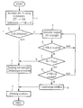
- the flowchart illustrates an embodiment of a method for controlling the timing for initiating ignition (ignition timing) in a direct injection spark ignition internal combustion engine with spark-guided combustion process.
- the triggering of the ignition is prepared in a step 1.
- the ignition timing ZZP is calculated as a function of, for example, load and speed of the internal combustion engine from the electronic operation control unit (not shown) of the internal combustion engine or taken from a map.
- This predetermined ignition time ZZP is usually indicated in degrees of the crankshaft angle (x ° CA). Since the recovery of such a given ignition timing is known in the art, will not be discussed in detail.
- the given ignition timing (x ° CA) is assigned a time range (x ° CA ⁇ ⁇ ) within which the ignition is to be triggered in any case.
- the actual ignition point should only be slightly corrected from the given ignition point in order to ensure that the nominal values of the torque are reached.
- the predetermined time range x ° CA ⁇ ⁇ can be, for example, in the order of 2-6 ° CA.
- an ionization signal IS is generated in step 5 which characterizes the state of the fuel / air mixture in the ignition region.
- the ionization signal can be obtained, for example, in such a way that a constant voltage is applied to the serving as ignition spark plug and the electrical resistance of the ionization distance between the electrodes of the spark plug is measured.
- the resistance of the ionization path changes depending on the amount of fuel present in the ionization path.
- the ionization signal is thus directly linked to the air ratio ⁇ in the ignition range, so that instead of the ionization signal IS, the air ratio ⁇ derived therefrom could also be used for the now following correction of the ignition time.
- step 5 the ionization signal is obtained with a high sampling frequency of, for example, 0.1 ° CA, so that the subsequent correction process takes place in correspondingly small steps.
- step 6 it is first checked whether the beginning of the predetermined time range x ° CA ⁇ ⁇ has already been reached. If this is not the case, the program returns to step 5.
- step 7 If the beginning of the predetermined time range has been reached, it is checked in a step 7 whether the ionization signal IS has exceeded a triggering threshold IS lim . If this is the case, this is a sign that there is an ignitable mixture cloud in the ignition area. It can then be set and triggered according to steps 3 and 4, the ignition with normal ignition energy.
- the ionization signal IS has not yet reached the trigger threshold IS lim , it is checked in a step 8 whether the correction method is still in the predetermined time range of x ° CA ⁇ ⁇ . As long as the end of the predetermined time range has not been reached, the program returns to step 5. However, if the ionization signal IS has not yet reached the triggering threshold IS lim after the predetermined time period has elapsed, the ignition is nevertheless triggered. In this case, the ignition energy is first increased in a step 9 in order to take into account the possibly poor flammability of the fuel / air mixture in the ignition region.
- the ignition energy may e.g. be increased in such a way that to the spark plug, an increased voltage is applied and / or a spark band ignition is performed with multiple sequential ignitions or that, for example, in a high voltage / high frequency ignition (plasma ignition), the spark duration is increased.
- a spark band ignition is performed with multiple sequential ignitions or that, for example, in a high voltage / high frequency ignition (plasma ignition), the spark duration is increased.
- the ignition can be triggered according to step 4.
- the described correction method thus ensures a "fine control" of the ignition, by means of which the actual ignition time is adapted to the variations in the mixture propagation present in the spray-guided combustion process.
- the ionization signal used here represents a systemimmanentes Signal is obtained from the ignition itself.
- the "software" required for the correction process can be readily integrated into the electronic operating control device (engine control) of the internal combustion engine. Instead, the corresponding function may also be performed by a specific device such as an IC or a separate processor.
Landscapes
- Engineering & Computer Science (AREA)
- Chemical & Material Sciences (AREA)
- Combustion & Propulsion (AREA)
- Mechanical Engineering (AREA)
- General Engineering & Computer Science (AREA)
- Signal Processing (AREA)
- Electrical Control Of Ignition Timing (AREA)
- Ignition Installations For Internal Combustion Engines (AREA)
Description
Die vorliegende Erfindung betrifft ein Verfahren zum Steuern des Zeitpunkts zum Auslösen der Zündung (Zündzeitpunkt) einer Zündeinrichtung in einer Otto-Brennkraftmaschine mit Direkteinspritzung und strahlgeführtem Brennverfahren.The present invention relates to a method for controlling the timing for triggering the ignition (ignition timing) of an ignition device in a gasoline engine with direct injection and spray-guided combustion method.
Die Zündung in einer fremdgezündeten Otto-Brennkraftmaschine wird heute in Abhängigkeit von verschiedenen Betriebsparametern der Brennkraftmaschine gesteuert. Darunter befinden sich insbesondere die Last und Drehzahl der Brennkraftmaschine, die Kolbenposition und der Klopfzustand, um nur die wichtigsten zu nennen. Die Berechnung des Zündzeitpunktes wird von dem elektronischen Betriebssteuergerät (Motorsteuerung) der Brennkraftmaschine abhängig von diesen Parametern in Bezug auf die Erfassung des Kurbelwellenwinkels (°KW) berechnet. Dies erlaubt es, den Zündzeitpunkt bis auf ca. 0,1°KW genau vorzugeben und einzustellen.The ignition in a spark-ignited Otto internal combustion engine is controlled today in dependence on various operating parameters of the internal combustion engine. These include in particular the load and speed of the internal combustion engine, the piston position and the knocking state, to name just the most important. The calculation of the ignition timing is calculated by the electronic operation control apparatus (engine control) of the internal combustion engine depending on these parameters with respect to the detection of the crankshaft angle (° CA). This makes it possible to specify the ignition timing to about 0.1 ° CA exactly and adjust.
Das strahlgeführte Brennverfahren in der Otto-Brennkraftmaschine ist darauf angewiesen, dass zum Zeitpunkt der Zündung eine zündfähige Gemischwolke an der Zündeinrichtung vorhanden ist. Hierzu ist erforderlich, dass das Kraftstoff/Luft-Gemisch im Zündbereich einen vorgegebenen Wert erreicht, dass also ausreichend Kraftstoff im Zündbereich vorhanden ist. Falls aus irgendwelchen Gründen kein oder zu wenig Kraftstoff vorhanden ist, kann die Gemischwolke durch die Zündeinrichtung nicht entflammt werden. Dies kann insbesondere dann eintreten, wenn zwar eine gewünschte Gemischwolke entsteht, aber nicht zum eingestellten Zündzeitpunkt. Verursacht wird dies im allgemeinen dadurch, dass aufgrund von Unzulänglichkeiten des Kraftstoffinjektors (Fertigungstoleranzen, Verschmutzungen, Alterungen, etc.) die Strahlaufbereitung und -ausbreitung mangelhaft sind. Es kommt dann zu Verbrennungsaussetzern, einem Anstieg der Schadstoffemissionen und Fahrbarkeitsnachteilen.The spray-guided combustion process in the Otto internal combustion engine is dependent on the fact that at the time of ignition an ignitable mixture cloud is present at the ignition device. For this purpose, it is necessary that the fuel / air mixture reaches a predetermined value in the ignition range, ie that there is sufficient fuel in the ignition range. If, for whatever reason, there is no or too little fuel, the mixture cloud can not be ignited by the ignition device. This can occur, in particular, when a desired mixture cloud is formed, but not at the set ignition point. This is generally caused by inadequate jet preparation and dispersion due to fuel injector deficiencies (manufacturing tolerances, soiling, aging, etc.). It happens then Combustion misfires, an increase in pollutant emissions and driveability disadvantages.
Aus
Der vorliegenden Erfindung liegt die Aufgabe zugrunde, ein Verfahren zum Steuern des Zeitpunktes zum Auslösen der Zündung einer Zündeinrichtung in einer Otto-Brennkraftmaschine mit Direkteinspritzung und strahlgeführtem Brennverfahren anzugeben, das den Zustand des Kraftstoff/Luft-Gemisches im Zündbereich berücksichtigt.The present invention has for its object to provide a method for controlling the timing for triggering the ignition of an ignition device in a gasoline engine with direct injection and spray-guided combustion method, which takes into account the state of the fuel / air mixture in the ignition.
Diese Aufgabe wird durch das im Patentanspruch 1 definierte Verfahren gelöst.This object is achieved by the method defined in claim 1.
Das erfindungsgemäße Verfahren geht davon aus, dass ein Zündzeitpunkt in üblicher Weise in Abhängigkeit von Betriebsparametern der Brennkraftmaschine wie Last und Drehzahl vorgegeben wird. Der vorgegebene Zündzeitpunkt wird dann in Abhängigkeit von einem Ionisationssignal, das den Ionisierungszustand des Kraftstoff/Luft-Gemisches im Zündbereich der Zündeinrichtung darstellt, so korrigiert, dass im Zündzeitpunkt eine möglichst optimale Zündfähigkeit des Gemisches im Zündbereich vorhanden ist.The method according to the invention assumes that an ignition point is specified in a customary manner as a function of operating parameters of the internal combustion engine, such as load and rotational speed. The predetermined ignition time is then corrected as a function of an ionization signal, which represents the ionization state of the fuel / air mixture in the ignition of the ignition device, that at ignition optimum ignition capability of the mixture is present in the ignition.
Das Ionisationssignal (Ionenstromsignal) wird nach irgendeiner vorbekannten Messmethode gewonnen. Ionisierungssignale werden beispielsweise bereits zur Klopfregelung, zum Überprüfen von Verbrennungsaussetzer-Erkennungseinrichtungen (z.B.
Die Korrektur des vorgegebenen Zündzeitpunktes stellt gewissermaßen eine überlagerte "Regelung" bzw. "Feinregelung" des Zündzeitpunktes dar, durch die der tatsächliche Zündzeitpunkt kurz vor oder kurz nach den berechneten (vorgegebenen) Zündzeitpunkt verlegt wird. Die tatsächliche Zündung erfolgt dann zu einem Zeitpunkt, zu dem aufgrund des Ionisationssignals auf eine zündfähige Gemischwolke im Zündbereich geschlossen werden kann.The correction of the predetermined ignition point effectively represents a superimposed "regulation" or "fine regulation" of the ignition point, by which the actual ignition point is shifted shortly before or shortly after the calculated (predetermined) ignition point. The actual ignition then takes place at a time at which, due to the ionization signal, an ignitable mixture cloud in the ignition region can be closed.
Erfindungsgemäß wird die Zündung ausgelöst, sobald das Ionisationssignal oder eine davon abhängige Größe wie z.B. der λ-Wert des Kraftstoff/Luft-Gemisches eine Auslöseschwelle erreicht hat, sofern die Auslöseschwelle innerhalb eines vorgegebenen relativ kleinen Zeitbereiches erreicht wird.According to the invention, the ignition is triggered as soon as the ionization signal or a variable depending therefrom, e.g. the λ value of the fuel / air mixture has reached a triggering threshold, provided that the triggering threshold is reached within a predetermined relatively small time range.
Im übrigen erfolgt die Auslösung der Zündung, wenn die Auslöseschwelle bereits vor dem vorgegebenen Zeitbereich erreicht wird, erst zu Beginn des vorgegebenen Zeitbereiches und, wenn die Auslöseschwelle nicht vor Ablauf des vorgegebenen Zeitbereiches erreicht wird, am Ende des vorgegebenen Zeitbereiches. Im letzteren Fall sollte die Zündung mit einer besonders hohen Zündenergie erfolgen, um die möglicherweise schlechtere Entflammbarkeit des Kraftstoff/Luft-Gemisches im Zündbereich "auszugleichen".Moreover, the triggering of the ignition, if the triggering threshold is reached before the predetermined time range, only at the beginning of the predetermined time range and, if the triggering threshold is not reached before the expiry of the predetermined time range, at the end of the predetermined time range. In the latter case, the ignition should be done with a particularly high ignition energy to "compensate" for the possibly worse flammability of the fuel / air mixture in the ignition.
Durch die Vorgabe des Zeitbereiches wird sichergestellt, dass der vorgegebene Zündzeitpunkt durch die erfindungsgemäß vorgesehene Korrektur in Abhängigkeit von dem Ionisationssignal nur um kleine Werte verändert wird. Ansonsten besteht die Gefahr, dass die Sollwerte für das Drehmoment der Brennkraftmaschine nicht eingehalten werden können.By specifying the time range, it is ensured that the predetermined ignition time is changed only by small values as a result of the correction provided according to the invention as a function of the ionization signal. Otherwise, there is the danger that the setpoint values for the torque of the internal combustion engine can not be met.
Schwankungen in der Ausbreitung des Kraftstoff/Luft-Gemisches und damit Zustände mangelnder Zündfähigkeit des Gemisches im Zündbereich treten insbesondere bei Teillast auf, wenn die Brennkraftmaschine im Schichtbetrieb mit magerem Kraftstoff/Luft-Gemisch arbeitet. Die Korrektur des vorgegebenen Zündzeitpunktes in Abhängigkeit von dem Ionisationssignal kann daher auf den Schichtbetrieb der Brennkraftmaschine beschränkt werden.Fluctuations in the propagation of the fuel / air mixture and thus states lack of ignitability of the mixture in the ignition area occur in particular at partial load when the internal combustion engine operates in shifts with lean fuel / air mixture. The correction of the predetermined ignition timing as a function of the ionization signal can therefore be limited to the stratified operation of the internal combustion engine.
Ferner kann es zweckmäßig sein, eine Adaption des Ionisati onssignals in bestimmten Betriebsbereichen vorzunehmen. Wenn beispielsweise die Bewegung des Gemisches im Brennraum gering ist, was insbesondere für den Leerlauf der Brennkraftmaschine zutrifft, so sollte das Ionisationssignal so adaptiert werden, dass es einen entsprechend großen Abstand zur Rauschgrenze hat.Furthermore, it may be appropriate to adapt the Ionisati onssignals in certain operating areas. For example, if the movement of the mixture in the combustion chamber is low, which is especially for the idling of the internal combustion engine is true, so the ionization signal should be adapted so that it has a correspondingly large distance to the noise limit.
Weitere vorteilhafte Ausgestaltungen der Erfindung gehen aus den Unteransprüchen hervor.Further advantageous embodiments of the invention will become apparent from the dependent claims.
Anhand der einzigen Figur, die ein Flussdiagramm eines Ausführungsbeispiels des erfindungsgemäßen Verfahrens darstellt, werden weitere Einzelheiten der Erfindung erläutert.With reference to the single figure, which represents a flow chart of an embodiment of the method according to the invention, further details of the invention will be explained.
Das Flussdiagramm veranschaulicht ein Ausführungsbeispiel für ein Verfahren zum Steuern des Zeitpunktes zum Auslösen der Zündung (des Zündzeitpunktes) in einer Otto-Brennkraftmaschine (nicht gezeigt) mit Direkteinspritzung und strahlgeführtem Brennverfahren.The flowchart illustrates an embodiment of a method for controlling the timing for initiating ignition (ignition timing) in a direct injection spark ignition internal combustion engine with spark-guided combustion process.
Wie sich dem Flussdiagramm entnehmen lässt, wird in einem Schritt 1 das Auslösen der Zündung vorbereitet. Hierzu wird der Zündzeitpunkt ZZP in Abhängigkeit von beispielsweise Last und Drehzahl der Brennkraftmaschine von dem elektronischen Betriebssteuergerät (nicht gezeigt) der Brennkraftmaschine errechnet bzw. einem Kennfeld entnommen. Dieser vorgegebene Zündzeitpunkt ZZP wird üblicherweise in Grad des Kurbelwellenwinkels (x°KW) angegeben. Da die Gewinnung eines derartigen vorgegebenen Zündzeitpunktes im Stand der Technik bekannt ist, wird hierauf nicht näher eingegangen.As can be seen from the flowchart, the triggering of the ignition is prepared in a step 1. For this purpose, the ignition timing ZZP is calculated as a function of, for example, load and speed of the internal combustion engine from the electronic operation control unit (not shown) of the internal combustion engine or taken from a map. This predetermined ignition time ZZP is usually indicated in degrees of the crankshaft angle (x ° CA). Since the recovery of such a given ignition timing is known in the art, will not be discussed in detail.
Dem vorgegebenen Zündzeitpunkt (x°KW) wird ein Zeitbereich (x°KW ± δ) zugeordnet, innerhalb dessen die Zündung auf jeden Fall ausgelöst werden soll. Wie bereits in der Beschreibungseinleitung erläutert, sollte der tatsächliche Zündzeitpunkt gegenüber dem vorgegebenen Zündzeitpunkt nur geringfügig korrigiert werden, um sicherzustellen, dass die Sollwerte des Drehmomentes erreicht werden. Der vorgegebene Zeitbereich x°KW ± δ kann beispielsweise in der Größenordnung von 2-6°KW liegen.The given ignition timing (x ° CA) is assigned a time range (x ° CA ± δ) within which the ignition is to be triggered in any case. As already explained in the introduction to the description, the actual ignition point should only be slightly corrected from the given ignition point in order to ensure that the nominal values of the torque are reached. The predetermined time range x ° CA ± δ can be, for example, in the order of 2-6 ° CA.
In einem Schritt 2 wird geprüft, ob sich die Brennkraftmaschine im Schichtbetrieb befindet. Wenn nämlich die Brennkraftmaschine bei Volllast mit einem Luftverhältnis von λ = 1 betrieben wird, so ist eine Korrektur des vorgegebenen Zündzeitpunktes im allgemeinen nicht erforderlich. Gemäß den Schritten 3 und 4 kann dann die Zündung mit normaler Zündenergie eingestellt und ausgelöst werden.In a
Befindet sich dagegen die Brennkraftmaschine bei Teillast im Schichtbetrieb mit magerer Verbrennung, so wird im Schritt 5 ein Ionisationssignal IS erzeugt, das den Zustand des Kraftstoff/Luft-Gemisches im Zündbereich charakterisiert. Das Ionisationssignal kann beispielsweise in der Weise gewonnen werden, dass eine konstante Spannung an die als Zündeinrichtung dienende Zündkerze angelegt und der elektrische Widerstand der Ionisationsstrecke zwischen den Elektroden der Zündkerze gemessen wird. Der Widerstand der Ionisationsstrecke ändert sich in Abhängigkeit von der Menge des in der Ionisationsstrecke vorhandenen Kraftstoffs. Das Ionisationssignal ist somit unmittelbar mit dem Luftverhältnis λ im Zündbereich verknüpft, so dass für die nun folgende Korrektur des Zündzeitpunktes anstelle des Ionisationssignals IS auch das hieraus abgeleitete Luftverhältnis λ verwendet werden könnte.If, on the other hand, the internal combustion engine is under partial load in stratified operation with lean combustion, an ionization signal IS is generated in
Da im übrigen im Stand der Technik zahlreiche technische Verfahren zum Messen des Ionisationszustandes im Zündbereich bekannt sind, wird hierauf nicht näher eingegangen. Zu beachten ist jedoch, dass im Schritt 5 das Ionisationssignal mit einer hohen Abtastfrequenz von beispielsweise 0,1°KW gewonnen wird, so dass das daran anschließende Korrekturverfahren in entsprechend kleinen Schritten abläuft.Moreover, since numerous technical methods for measuring the ionization state in the ignition region are known in the prior art, this will not be discussed in detail. It should be noted, however, that in
In einem Schritt 6 wird zunächst geprüft, ob bereits der Beginn des vorgegebenen Zeitbereiches x°KW ± δ erreicht ist. Ist dies nicht der Fall, so kehrt das Programm zu dem Schritt 5 zurück.In a
Wenn der Beginn des vorgegebenen Zeitbereiches erreicht ist, wird in einem Schritt 7 geprüft, ob das Ionisationssignal IS eine Auslöseschwelle ISlim überschritten hat. Falls dies der Fall ist, so ist dies ein Zeichen dafür, dass im Zündbereich eine zündfähige Gemischwolke vorliegt. Es kann dann gemäß den Schritten 3 und 4 die Zündung mit normaler Zündenergie eingestellt und ausgelöst werden.If the beginning of the predetermined time range has been reached, it is checked in a
Hat das Ionisationssignal IS die Auslöseschwelle ISlim noch nicht erreicht, so wird in einem Schritt 8 geprüft, ob sich das Korrekturverfahren noch in dem vorgegebenen Zeitbereich von x°KW ± δ befindet. Solange das Ende des vorgegebenen Zeitbereiches nicht erreicht ist, geht das Programm zu dem Schritt 5 zurück. Wenn jedoch nach Ablauf des vorgegebenen Zeitbereichs das Ionisationssignal IS die Auslöseschwelle ISlim noch nicht erreicht hat, wird die Zündung dennoch ausgelöst. Hierbei wird zunächst in einem Schritt 9 die Zündenergie erhöht, um die möglicherweise schlechte Entflammbarkeit des Kraftstoff/Luft-Gemisches im Zündbereich zu berücksichtigen.If the ionization signal IS has not yet reached the trigger threshold IS lim , it is checked in a
Die Zündenergie kann z.B. in der Weise erhöht werden, dass an die Zündkerze eine erhöhte Spannung angelegt wird und/oder eine Funkenbandzündung mit mehreren sequentiellen Zündungen durchgeführt wird oder dass beispielsweise bei einer Hochspannungs-/Hochfrequenzzündung (Plasmazündung) die Funkendauer erhöht wird.The ignition energy may e.g. be increased in such a way that to the spark plug, an increased voltage is applied and / or a spark band ignition is performed with multiple sequential ignitions or that, for example, in a high voltage / high frequency ignition (plasma ignition), the spark duration is increased.
Wenn dann die Zündung mit erhöhter Zündenergie eingestellt ist, kann die Zündung gemäß dem Schritt 4 ausgelöst werden.If the ignition is then set with increased ignition energy, the ignition can be triggered according to step 4.
Das beschriebene Korrekturverfahren sorgt somit für eine "Feinregelung" der Zündung, durch die der tatsächliche Zündzeitpunkt an die beim strahlgeführten Brennverfahren vorhandenen Schwankungen der Gemischausbreitung angepasst wird. Das hierbei verwendete Ionisationssignal stellt ein systemimmanentes Signal dar, das aus der Zündeinrichtung selbst gewonnen wird. Die für das Korrekturverfahren erforderliche "Software" kann ohne weiteres in das elektronische Betriebssteuergerät (Motorsteuerung) der Brennkraftmaschine integriert sein. Statt dessen kann die entsprechende Funktion auch von einem speziellen Baustein wie einem IC oder einem gesonderten Prozessor ausgeführt werden.The described correction method thus ensures a "fine control" of the ignition, by means of which the actual ignition time is adapted to the variations in the mixture propagation present in the spray-guided combustion process. The ionization signal used here represents a systemimmanentes Signal is obtained from the ignition itself. The "software" required for the correction process can be readily integrated into the electronic operating control device (engine control) of the internal combustion engine. Instead, the corresponding function may also be performed by a specific device such as an IC or a separate processor.
Claims (7)
- Method for controlling the point for triggering the ignition (ignition point) of an ignition apparatus in a spark-ignition type internal combustion engine with direct injection and jet-controlled combustion method, wherein an ignition point (x °KW) is predetermined as a function of operating parameters of the internal combustion engine and the predetermined ignition point (x °KW) is corrected as a function of an ionisation signal (IS), which represents the state of ionisation of the fuel/air mixture in the ignition region of the ignition apparatus, to improve the ignitability of the mixture, in that ignition is triggered as soon as the ionisation signal (IS) or a variable (λ) dependent thereon reaches a trigger threshold (ISlim), in so far as the trigger threshold is reached within a predetermined time range (x °KW ± δ).
- Method according to claim 1, wherein a spark plug is used as the ignition apparatus,
characterised in that the ionisation signal (IS) is obtained by measuring the ionisation state between the electrodes of the spark plug. - Method according to claim 1 or 2,
characterised in that if the trigger threshold (ISlim) is already reached before the predetermined time range(x °KW ± δ), ignition is only triggered at the start of the predetermined time range. - Method according to claim 1 or 2,
characterised in that if the trigger threshold (ISlim) is not reached before the end of the predetermined time range(x °KW ± δ), ignition is triggered at the end of the predetermined time range. - Method according to claim 4,
characterised in that ignition is triggered at the end of the predetermined time range(x °KW ± δ) with increased ignition energy compared with the normal ignition energy. - Method according to one of the preceding claims,
characterised in that the predetermined ignition time is only corrected as a function of the ionisation signal (IS) in stratified operation of the internal combustion engine. - Method according to one of the preceding claims,
characterised in that the ionisation signal is adjusted as a function of the charging movement in the combustion chamber or other operating conditions of the internal combustion engine.
Applications Claiming Priority (2)
| Application Number | Priority Date | Filing Date | Title |
|---|---|---|---|
| DE10358701A DE10358701B4 (en) | 2003-12-15 | 2003-12-15 | Method for controlling the ignition timing in an Otto internal combustion engine |
| DE10358701 | 2003-12-15 |
Publications (3)
| Publication Number | Publication Date |
|---|---|
| EP1544444A1 EP1544444A1 (en) | 2005-06-22 |
| EP1544444B1 true EP1544444B1 (en) | 2008-05-07 |
| EP1544444B8 EP1544444B8 (en) | 2008-07-02 |
Family
ID=34485386
Family Applications (1)
| Application Number | Title | Priority Date | Filing Date |
|---|---|---|---|
| EP04105671A Expired - Lifetime EP1544444B8 (en) | 2003-12-15 | 2004-11-10 | Method of controlling the ignition angle of an internal combustion engine |
Country Status (2)
| Country | Link |
|---|---|
| EP (1) | EP1544444B8 (en) |
| DE (2) | DE10358701B4 (en) |
Family Cites Families (14)
| Publication number | Priority date | Publication date | Assignee | Title |
|---|---|---|---|---|
| SE508563C2 (en) * | 1994-02-22 | 1998-10-12 | Scania Cv Ab | Sensor for detecting degree of ionization in the combustion engine's combustion chamber and combustion engine equipped with ionization sensor |
| SE503171C2 (en) * | 1994-08-11 | 1996-04-15 | Mecel Ab | Method for controlling the timing of an internal combustion engine |
| DE19642654B4 (en) * | 1996-10-16 | 2004-02-05 | Daimlerchrysler Ag | Method for controlling the adjustable operating parameters of a direct-injection internal combustion engine |
| JP3264854B2 (en) * | 1997-02-19 | 2002-03-11 | 三菱電機株式会社 | Device for detecting combustion state of internal combustion engine |
| JP3619040B2 (en) * | 1999-01-19 | 2005-02-09 | 三菱電機株式会社 | Combustion state detection device for internal combustion engine |
| JP3505419B2 (en) * | 1999-01-27 | 2004-03-08 | 三菱電機株式会社 | Device for detecting combustion state of internal combustion engine |
| JP3523542B2 (en) * | 1999-09-27 | 2004-04-26 | 三菱電機株式会社 | Misfire detection device for internal combustion engine |
| DE10031554A1 (en) * | 2000-06-28 | 2002-01-10 | Bosch Gmbh Robert | Method and device for controlling a gasoline internal combustion engine with direct injection |
| DE10043694A1 (en) * | 2000-09-04 | 2002-03-14 | Bosch Gmbh Robert | Method for adaptive knock control of a gasoline direct injection internal combustion engine and corresponding device |
| DE10142493A1 (en) * | 2001-08-30 | 2003-04-03 | Bosch Gmbh Robert | Method for operating a direct injection internal combustion engine |
| JP2003138979A (en) * | 2001-10-30 | 2003-05-14 | Mitsubishi Electric Corp | Misfire detection device for internal combustion engine |
| JP3851583B2 (en) * | 2002-03-28 | 2006-11-29 | 三菱電機株式会社 | Knock control device for internal combustion engine |
| JP3614149B2 (en) * | 2002-04-17 | 2005-01-26 | 三菱電機株式会社 | Combustion state detection device for internal combustion engine |
| DE10236979C1 (en) * | 2002-08-13 | 2003-08-14 | Stiebel Eltron Gmbh & Co Kg | Combustion regulation method for IC engine employs switching function for providing calibration phase, regulation phase and engine cold-starting phase |
-
2003
- 2003-12-15 DE DE10358701A patent/DE10358701B4/en not_active Expired - Fee Related
-
2004
- 2004-11-10 EP EP04105671A patent/EP1544444B8/en not_active Expired - Lifetime
- 2004-11-10 DE DE502004007041T patent/DE502004007041D1/en not_active Expired - Lifetime
Also Published As
| Publication number | Publication date |
|---|---|
| DE10358701B4 (en) | 2008-01-31 |
| EP1544444B8 (en) | 2008-07-02 |
| EP1544444A1 (en) | 2005-06-22 |
| DE502004007041D1 (en) | 2008-06-19 |
| DE10358701A1 (en) | 2005-07-14 |
Similar Documents
| Publication | Publication Date | Title |
|---|---|---|
| EP0801226B1 (en) | Method and device for evaluating the quality of an air fuel mixture | |
| DE2939690C2 (en) | ||
| DE102008036477B4 (en) | Engine combustion condition detection apparatus and combustion condition detection method | |
| DE3309256C2 (en) | ||
| DE10057076B4 (en) | Ignition control device for internal combustion engines | |
| DE69319253T2 (en) | MULTIPLE SPARK IGNITION SYSTEM WITH VARIABLE NUMBER OF IGNITION SPARKS FOR AN INTERNAL INTERNAL COMBUSTION ENGINE | |
| DE19581041C2 (en) | Method for controlling the ignition timing of internal combustion engines | |
| EP0785346B1 (en) | Method of operating an internal combustion engine | |
| DE102012207904A1 (en) | Method for suppressing pre-ignition occurring before ignition timing in combustion chamber of engine, involves detecting occurrence or increased risk of pre-ignition and injecting water with modified injection characteristic | |
| DE102008035381B4 (en) | Engine combustion state detecting device | |
| DE69417843T2 (en) | Method of detecting autoignition | |
| DE102016125015A1 (en) | Control device for internal combustion engine | |
| DE3921616C2 (en) | ||
| DE3922128A1 (en) | IGNITION DEVICE FOR INTERNAL COMBUSTION ENGINES | |
| EP2561214A2 (en) | Method for operating a laser spark plug for an internal combustion engine | |
| EP1537320A2 (en) | Methods for operating a spark-ignition internal combustion engine | |
| DE102017222741B4 (en) | Abnormal combustion detection device for internal combustion engines | |
| EP1254313A2 (en) | Method for producing a sequence of high-voltage ignition sparks and high-voltage ignition device | |
| DE19859310A1 (en) | Engine control device | |
| EP0912828B1 (en) | Method for identifying knocking combustion in an internal combustion engine with an alternating current ignition system | |
| EP1317612B1 (en) | Method for operating an internal combustion engine, and a corresponding device | |
| WO2010124699A1 (en) | Method for suppressing irregular combustion in a combustion chamber of an internal combustion engine which especially occurs prior to a predetermined ignition point, and control device | |
| DE69417841T2 (en) | Misfire Detection Method | |
| WO1999020882A1 (en) | Method for starting an internal combustion engine | |
| DE19624877C2 (en) | Combustion control system for four-stroke engine with direct injection and associated process |
Legal Events
| Date | Code | Title | Description |
|---|---|---|---|
| PUAI | Public reference made under article 153(3) epc to a published international application that has entered the european phase |
Free format text: ORIGINAL CODE: 0009012 |
|
| AK | Designated contracting states |
Kind code of ref document: A1 Designated state(s): AT BE BG CH CY CZ DE DK EE ES FI FR GB GR HU IE IS IT LI LU MC NL PL PT RO SE SI SK TR |
|
| AX | Request for extension of the european patent |
Extension state: AL HR LT LV MK YU |
|
| 17P | Request for examination filed |
Effective date: 20051205 |
|
| AKX | Designation fees paid |
Designated state(s): DE FR GB IT |
|
| 17Q | First examination report despatched |
Effective date: 20060120 |
|
| GRAP | Despatch of communication of intention to grant a patent |
Free format text: ORIGINAL CODE: EPIDOSNIGR1 |
|
| GRAS | Grant fee paid |
Free format text: ORIGINAL CODE: EPIDOSNIGR3 |
|
| GRAA | (expected) grant |
Free format text: ORIGINAL CODE: 0009210 |
|
| AK | Designated contracting states |
Kind code of ref document: B1 Designated state(s): DE FR GB IT |
|
| REG | Reference to a national code |
Ref country code: GB Ref legal event code: FG4D Free format text: NOT ENGLISH |
|
| RAP2 | Party data changed (patent owner data changed or rights of a patent transferred) |
Owner name: CONTINENTAL AUTOMOTIVE GMBH |
|
| REF | Corresponds to: |
Ref document number: 502004007041 Country of ref document: DE Date of ref document: 20080619 Kind code of ref document: P |
|
| PLBE | No opposition filed within time limit |
Free format text: ORIGINAL CODE: 0009261 |
|
| STAA | Information on the status of an ep patent application or granted ep patent |
Free format text: STATUS: NO OPPOSITION FILED WITHIN TIME LIMIT |
|
| PGFP | Annual fee paid to national office [announced via postgrant information from national office to epo] |
Ref country code: IT Payment date: 20081120 Year of fee payment: 5 |
|
| 26N | No opposition filed |
Effective date: 20090210 |
|
| PGFP | Annual fee paid to national office [announced via postgrant information from national office to epo] |
Ref country code: FR Payment date: 20081113 Year of fee payment: 5 |
|
| PGFP | Annual fee paid to national office [announced via postgrant information from national office to epo] |
Ref country code: GB Payment date: 20081117 Year of fee payment: 5 |
|
| GBPC | Gb: european patent ceased through non-payment of renewal fee |
Effective date: 20091110 |
|
| REG | Reference to a national code |
Ref country code: FR Ref legal event code: ST Effective date: 20100730 |
|
| PG25 | Lapsed in a contracting state [announced via postgrant information from national office to epo] |
Ref country code: FR Free format text: LAPSE BECAUSE OF NON-PAYMENT OF DUE FEES Effective date: 20091130 |
|
| PG25 | Lapsed in a contracting state [announced via postgrant information from national office to epo] |
Ref country code: GB Free format text: LAPSE BECAUSE OF NON-PAYMENT OF DUE FEES Effective date: 20091110 |
|
| PG25 | Lapsed in a contracting state [announced via postgrant information from national office to epo] |
Ref country code: IT Free format text: LAPSE BECAUSE OF NON-PAYMENT OF DUE FEES Effective date: 20091110 |
|
| PGFP | Annual fee paid to national office [announced via postgrant information from national office to epo] |
Ref country code: DE Payment date: 20131130 Year of fee payment: 10 |
|
| REG | Reference to a national code |
Ref country code: DE Ref legal event code: R119 Ref document number: 502004007041 Country of ref document: DE |
|
| PG25 | Lapsed in a contracting state [announced via postgrant information from national office to epo] |
Ref country code: DE Free format text: LAPSE BECAUSE OF NON-PAYMENT OF DUE FEES Effective date: 20150602 |