EP1544106A1 - Drain notamment pour mât support de réacteur - Google Patents
Drain notamment pour mât support de réacteur Download PDFInfo
- Publication number
- EP1544106A1 EP1544106A1 EP04106283A EP04106283A EP1544106A1 EP 1544106 A1 EP1544106 A1 EP 1544106A1 EP 04106283 A EP04106283 A EP 04106283A EP 04106283 A EP04106283 A EP 04106283A EP 1544106 A1 EP1544106 A1 EP 1544106A1
- Authority
- EP
- European Patent Office
- Prior art keywords
- drain
- trailing edge
- drain according
- duct
- section
- Prior art date
- Legal status (The legal status is an assumption and is not a legal conclusion. Google has not performed a legal analysis and makes no representation as to the accuracy of the status listed.)
- Granted
Links
- 238000011144 upstream manufacturing Methods 0.000 claims description 2
- 238000011084 recovery Methods 0.000 claims 1
- 210000005069 ears Anatomy 0.000 description 6
- 210000002816 gill Anatomy 0.000 description 3
- 230000000052 comparative effect Effects 0.000 description 2
- 239000012530 fluid Substances 0.000 description 2
- 230000006870 function Effects 0.000 description 2
- 238000002513 implantation Methods 0.000 description 2
- 238000012550 audit Methods 0.000 description 1
- 230000001186 cumulative effect Effects 0.000 description 1
- 238000010586 diagram Methods 0.000 description 1
- 230000002349 favourable effect Effects 0.000 description 1
- 239000000446 fuel Substances 0.000 description 1
- 238000009434 installation Methods 0.000 description 1
- 239000007788 liquid Substances 0.000 description 1
Images


Classifications
-
- B—PERFORMING OPERATIONS; TRANSPORTING
- B64—AIRCRAFT; AVIATION; COSMONAUTICS
- B64D—EQUIPMENT FOR FITTING IN OR TO AIRCRAFT; FLIGHT SUITS; PARACHUTES; ARRANGEMENT OR MOUNTING OF POWER PLANTS OR PROPULSION TRANSMISSIONS IN AIRCRAFT
- B64D29/00—Power-plant nacelles, fairings or cowlings
- B64D29/02—Power-plant nacelles, fairings or cowlings associated with wings
-
- B—PERFORMING OPERATIONS; TRANSPORTING
- B64—AIRCRAFT; AVIATION; COSMONAUTICS
- B64C—AEROPLANES; HELICOPTERS
- B64C1/00—Fuselages; Constructional features common to fuselages, wings, stabilising surfaces or the like
- B64C1/14—Windows; Doors; Hatch covers or access panels; Surrounding frame structures; Canopies; Windscreens accessories therefor, e.g. pressure sensors, water deflectors, hinges, seals, handles, latches, windscreen wipers
- B64C1/1407—Doors; surrounding frames
- B64C1/1453—Drain masts
Definitions
- the present invention relates to drains installed on the fairings of rear mast and intended to evacuate any leakage of liquids that may flammable and from tanks, pipes or systems hydraulics located above said rear fairing in a structure integrated into the reactor mast and more commonly referred to as “rear secondary structure (RSS) ".
- RSS rear secondary structure
- drains are ducts of generally elliptical section not negligible, for example reaching a dimension of 1 50 mm X 58 mm for larger aircraft, which protrude from the rear of the rear fairing of the reactor mast and generate a drag that affects the fuel consumption.
- the present invention aims to overcome these various disadvantages in proposing a new geometry for this type of drain.
- said conduit may be symmetrical by vertical plane containing said trailing edge, having an opening of drainage on its two opposite side walls, whose major axis is parallel to the trailing edge and these two openings may be symmetrical.
- Such a drain forms a flattened conduit provided on its lateral flanks, substantially planar, elongated openings in the form of gills ensuring a more efficient drainage thanks to the training, at the exit of the ears, from zones of depression greater than those generated at the outlet of the drains traditional, the drain according to the invention also generating a drag significantly reduced in comparison with the same traditional drains of equivalent drainage capacity.
- the ears of such a drain may have, in comparison with a conventional drain with an elliptical drainage section of 4900 mm 2 , 120 mm long axis and 52 mm small and with equivalent drainage capacity, a generally rectangular shape of 230 mm long and 11 mm wide, which, moreover, is likely to prohibit any intrusion of volatile particular.
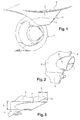
- FIG. 1 shows diagrammatically in 1 a reactor of aircraft, in 2 the support mast of the reactor, called reactor mast, in 3 la structure called RSS or "rear secondary structure", that is to say rear secondary structure and in 4 the rear mast fairing located at close proximity to the back of the reactor 1.
- RSS support mast of the reactor
- rear secondary structure that is to say rear secondary structure
- rear mast fairing located at close proximity to the back of the reactor 1.
- RSS structure In the RSS structure are traditionally installed various systems in equipment such as fire extinguishers, tanks and fluid lines hydraulics, which can leak fluid, for example as a result of close to pipes. That's why a drain 5 is disposed at the lower part of the RSS zone, on the trailing edge 6 of this last.
- this drain 5 straddling the trailing edge 6, has an elliptical section, the minor axis 7 (FIG. 2) being horizontal and orthogonal to the trailing edge 6.
- the drain 5 has its longitudinal axis slightly raised (of the order of 7 °) to above the axis of the aerodynamic flow in flight.
- 8 in Figure 3 is indicated the major axis of the elliptical section of the drain whose output is in bevel, the exit plane being parallel to the trailing edge 6.
- the drain 5 protrudes at the rear of the trailing edge by a distance 9 of the order of 120 mm for a drain of 126 mm of major axis 8 and 58 mm of small axis 7, the axis dimensions being taken externally to the duct forming the drain whose wall thickness is of the order of 3 mm.
- FIG. 4 illustrates an embodiment of a drain 10 according to the invention, instead of the drain 5, consisting of a flattened duct on its flanks. To better understand the shape of the drain 10, we will also refer to in Figures 5 to 8.
- FIG. 5 is a side elevational view of the drain 10 appear on a lateral flank 11a substantially plane of the drain an opening inclined lug 12 of narrow rectangular general section and more precisely in the form of parallelogram and major axis 13 parallel to the edge 6 of the structure 3, the trailing edge 14 of the drain 10 being also preferably parallel to the edge 6.
- FIG. 8 shows in comparison the respective sections of the drain 10 according to the invention and drain 5, taken perpendicular to their axis.
- the section 15 of the drain 10 is rectangular with rounded angles to aerodynamic purposes and has a length L slightly greater than long axis (8) of the elliptical section 16 of the drain 5, while the width I of section 15 is slightly smaller than the minor axis (7).
- FIG. 7 which is a section parallel to the axis of the drain 10, observes that the latter is symmetrical with respect to the vertical plane containing the trailing edges 6 and 14 and that the conduit forming the drain ends with a Part 19 with ogive section also for aerodynamic purposes.
- the lugs 12 do not extend up to upper and lower edges of the drain 10 and stop ( Figure 8) at beginning of the rounded areas 20 of the drain angles. It therefore remains a small lower area of the drain that would not be drained, too, for there to overcome, a hole may be formed in the wall of the bottom of the drain 10, at near the trailing edge 14, as symbolized at 21 in FIG.
- the width of the ears 12 is of the order of 11 mm for a length 13 (FIG. 5) of the order of 238 mm,
- FIG. 9 illustrates the aerodynamic flow at the right of a 12 of the drain 10.
- the wall 24 of the end portion 19, delimiting the hearing 12 by its edge 25 is slightly back towards the interior of the drain, compared to the adjacent portion 26 intermediate between the portion 24 and the nose of the nose (14), which portion 26 is in the curvature (dashed 27) of the sidewall 11b of the drain.
- In 28 is created a zone of maximum depression flexing of an angle a few degrees the flowing stream of flow E to the inside of the drain to height of hearing 12.
- the flow E is then taken up by the outer face of the wall 24 and accelerated in 29.
- the role of the wall 24 is to resume this flow to prevent it from enters the drain.
- the angle formed between the tangent to the wall 26 and the outer face of the wall 24 is of the order of 30 °.
- Figures 10 illustrate a practical embodiment of the drain 10 according to which the drain portion proper 10 'is extended in its part recess in the "bow” formed by the trailing edge 6 of the structure 3, two symmetrical parts 10 "intended to come flush with the walls of both flanks of structure 3, the "bow” of this the last being cut accordingly to receive the set 10'-10 ".
- louvers 12 are parallel to the trailing edge 6 and in the immediate vicinity of this edge, and on both sides.
- louvers 12 can of course vary in function for example of the desired drainage capacity.
- the ratio between the length (13) and the width (22) of each lute 12 is twenty, but it could be different according to the applications, in particular according to the drainage capacity desired, the passage section of the ears being a function of this capacity.
- the width 22 must remain on the order of 10 to 20 mm to avoid the intrusion of volatile.
- the cumulative passage section of the two gills 12 will be slightly larger than the internal section of the drain duct 10 in upstream of the ears.
- the shape of the outer section of the drain shown with an outline rectangular 15 in FIG. 8 may also vary, it being understood that the width I will be slightly smaller than the small axis of the elliptic capacitance section drain of equivalent drainage, the ratio of the length L of section 15 to the width I being preferably of the order of 2.8 as illustrated in the example of FIG. 8, this ratio being able to evolve in the range 1-10.
- flanks 11a, 11b of the drain 10 are preferably flat but could possibly be slightly convex.
- the aerodynamic behavior of the drain 10 in flight is very favorable in comparison with that of the drain 5. Indeed, the drag generated is significantly reduced, in particular because of the creation of the area suction on the flanks of the drain, to the right of the ears 12, and not to the right of the rear nose (19) of the drain which is profiled, while in the conventional drain 5, the suction is created behind the drain, the depression thus formed downstream participating directly and more fully in the creation of a trail.
- the drain 10 is protruding on the trailing edge 6, axially to the aerodynamic flow, a distance of the order of 120 mm equivalent to that (9) of the drain 5.
Landscapes
- Engineering & Computer Science (AREA)
- Aviation & Aerospace Engineering (AREA)
- Mechanical Engineering (AREA)
- Structures Of Non-Positive Displacement Pumps (AREA)
- Jet Pumps And Other Pumps (AREA)
- Cyclones (AREA)
- Sewage (AREA)
- Nitrogen Condensed Heterocyclic Rings (AREA)
- Air-Conditioning For Vehicles (AREA)
- Body Structure For Vehicles (AREA)
- Vehicle Body Suspensions (AREA)
Abstract
Description
- d'un conduit d'axe sensiblement horizontal,
- de section générale sensiblement rectangulaire, prise dans un plan parallèle audit bord de fuite,
- fermé à son extrémité externe par une partie terminale de section sensiblement ogivale prise dans l'axe du conduit,
- et comportant au moins une ouverture de drainage de forme allongée sur au moins l'une des parois latérales opposées.
- Figure 1 est une vue en perspective de l'arrière d'un mât réacteur ;
- Figure 2 est une vue partielle agrandie montrant plus en détail le drain de la partie dénommée « rear secondary structure RSS » de mât ;
- Figure 3 est une vue de côté du drain de la figure 2 ;
- Figure 4 est une vue analogue à la figure 2 représentant un drain selon l'invention au lieu et place du drain conventionnel ;
- Figure 5 est une vue de côté schématique du drain de la figure 4 ;
- Figure 6 est une vue en coupe suivant la ligne VII-VII du drain de la figure 5 ;
- Figure 7 est une vue schématique en coupe suivant la ligne VII-VII du drain de la figure 5 ;
- Figure 8 est une vue comparative entre les sections d'un drain selon l'invention et d'un drain conventionnel à section elliptique ;
- Figure 9 est un schéma illustrant l'écoulement aérodynamique à hauteur d'une ouie du drain de l'invention, et
- Figure 10 est une vue schématique montrant l'implantation du drain sur la structure RSS ;
Claims (9)
- Drain notamment pour mât (3) support de réacteur d'aéronef, agencé sur le bord de fuite (6) de la structure secondaire arrière (3) dudit mât, caractérisé en ce qu'il est constitué :d'un conduit (10) d'axe sensiblement horizontal,de section générale (15) sensiblement rectangulaire, prise dans un plan parallèle audit bord de fuite (6),fermé à son extrémité externe par une partie terminale (19) de section sensiblement ogivale prise dans l'axe du conduit,et comportant au moins une ouverture de drainage (12) de forme allongée sur au moins l'une des parois latérales opposées (1 1 a, 11 b).
- Drain suivant la revendication 1, caractérisé en ce que ledit conduit (10) est symétrique par rapport au plan vertical contenant ledit bord de fuite (6).
- Drain suivant la revendication 1 ou 2, caractérisé en ce que ledit conduit (10) comporte sur ses deux parois latérales opposées (11a, 11b) deux ouvertures de drainage (12), de forme allongée, dont le grand axe (13) est parallèle au bord de fuite (6).
- Drain suivant la revendication 3, caractérisé en ce que lesdites ouvertures de drainage (12) sont symétriques.
- Drain suivant l'une des revendications 1 à 4, caractérisé en ce que lesdites ouvertures de drainage (12) sont disposées sensiblement à hauteur dudit bord de fuite (6) de la structure secondaire arrière (3), en amont de ladite partie terminale (19).
- Drain suivant l'une des revendications 1 à 5, caractérisé en ce que la largeur (22) de chaque ouverture de drainage (12) est de l'ordre de 10 à 20 mm.
- Drain suivant l'une des revendications 1 à 6, caractérisé en ce que le rapport entre la longueur (L) de ladite section générale (15) du conduit de drain (10) prise dans un plan parallèle audit bord de fuite (6), et la largeur (l) est dans la plage 1-10.
- Drain suivant l'une des revendications 1 à 7, caractérisé en ce que chaque ouverture (12) est définie, dans le sens de la largeur (22), entre un bord de l'un des flancs (11a, 11b) et un bord (25) d'une partie (24) de ladite partie terminale à section en ogive (19), ladite partie (24) étant dirigée vers l'intérieur du drain (10) en sorte de définir un plan de reprise du flux (E) d'écoulement aérodynamique le long dudit flanc (11a, 11 b).
- Drain suivant la revendication 8, caractérisé en ce que ladite partie rentrante (24) forme avec la tangente à la partie adjacente (26) de ladite partie terminale (19) un angle de l'ordre de 30°.
Applications Claiming Priority (2)
| Application Number | Priority Date | Filing Date | Title |
|---|---|---|---|
| FR0314891A FR2864031B1 (fr) | 2003-12-18 | 2003-12-18 | Drain notamment pour mat support de reacteur |
| FR0314891 | 2003-12-18 |
Publications (2)
| Publication Number | Publication Date |
|---|---|
| EP1544106A1 true EP1544106A1 (fr) | 2005-06-22 |
| EP1544106B1 EP1544106B1 (fr) | 2006-07-05 |
Family
ID=34508692
Family Applications (1)
| Application Number | Title | Priority Date | Filing Date |
|---|---|---|---|
| EP04106283A Expired - Lifetime EP1544106B1 (fr) | 2003-12-18 | 2004-12-03 | Drain notamment pour mât support de réacteur |
Country Status (7)
| Country | Link |
|---|---|
| US (1) | US7121512B2 (fr) |
| EP (1) | EP1544106B1 (fr) |
| AT (1) | ATE332268T1 (fr) |
| CA (1) | CA2489717C (fr) |
| DE (1) | DE602004001438T2 (fr) |
| ES (1) | ES2266997T3 (fr) |
| FR (1) | FR2864031B1 (fr) |
Cited By (2)
| Publication number | Priority date | Publication date | Assignee | Title |
|---|---|---|---|---|
| US10266273B2 (en) | 2013-07-26 | 2019-04-23 | Mra Systems, Llc | Aircraft engine pylon |
| US11028779B2 (en) | 2019-01-31 | 2021-06-08 | Raytheon Technologies Corporation | Gas turbine engine bypass drainage systems |
Families Citing this family (8)
| Publication number | Priority date | Publication date | Assignee | Title |
|---|---|---|---|---|
| DE102007026060A1 (de) * | 2007-06-01 | 2008-12-04 | Rolls-Royce Deutschland Ltd & Co Kg | Entlüftung für das Schmierölsystem eines Strahltriebwerks |
| US20100327115A1 (en) * | 2009-04-30 | 2010-12-30 | Alexis Cenko | Aircraft pod store separation characteristics |
| EP2681111B1 (fr) | 2011-03-01 | 2016-07-06 | Short Brothers Plc | Dispositif d'évacuation |
| US9315253B2 (en) * | 2013-09-18 | 2016-04-19 | Goodrich Corporation | Drain masts |
| FR3014134B1 (fr) * | 2013-12-04 | 2015-12-11 | Snecma | Dispositif de retention de fluides draines pour un ensemble propulsif |
| JP6419437B2 (ja) * | 2014-02-28 | 2018-11-07 | 三菱航空機株式会社 | 航空機のエンジンパイロンおよび航空機 |
| EP3028941B1 (fr) * | 2014-12-03 | 2019-07-10 | AIRBUS HELICOPTERS DEUTSCHLAND GmbH | Dispositif d'extrémité de drainage des fluides provenant d'un espace creux dans un véhicule |
| US10823057B2 (en) | 2017-03-08 | 2020-11-03 | Rohr, Inc. | Outlet tube vent with flow energizing features |
Citations (2)
| Publication number | Priority date | Publication date | Assignee | Title |
|---|---|---|---|---|
| FR2735444A3 (fr) * | 1995-06-13 | 1996-12-20 | Maier Simon | Carenage aerodynamique de la bride a conduit(s) de drainage sur pylone de suspension de reacteur d'avion |
| FR2741321A1 (fr) * | 1995-11-18 | 1997-05-23 | Daimler Benz Aerospace Ag | Agencement de dispositifs d'echappement pour le degagement de vapeurs cryogenes inflammables |
Family Cites Families (9)
| Publication number | Priority date | Publication date | Assignee | Title |
|---|---|---|---|---|
| US2643832A (en) * | 1949-01-26 | 1953-06-30 | Imp Trust For The Encouragemen | Aerodynamic lift-producing device |
| GB1237540A (en) * | 1968-05-02 | 1971-06-30 | Avimo Ltd | Improvements in or relating to static vents in aircraft or parts thereof |
| US4782658A (en) * | 1987-05-07 | 1988-11-08 | Rolls-Royce Plc | Deicing of a geared gas turbine engine |
| US5104069A (en) * | 1990-10-29 | 1992-04-14 | The Boeing Company | Apparatus and method for ejecting matter from an aircraft |
| US5269135A (en) * | 1991-10-28 | 1993-12-14 | General Electric Company | Gas turbine engine fan cooled heat exchanger |
| US5552576A (en) * | 1992-02-21 | 1996-09-03 | The Bf Goodrich Company | Modular drainmast for aircraft |
| US5285636A (en) * | 1992-10-28 | 1994-02-15 | General Electric Company | Diagnostic drain mast for a gas turbine engine |
| DE4408493C1 (de) * | 1994-03-14 | 1995-02-09 | Deutsche Aerospace Airbus | Vorrichtung zur Abwasserdrainage aus Flugzeugen |
| US6425554B1 (en) * | 2000-10-12 | 2002-07-30 | The B. F. Goodrich Company | Bottom discharge drainmast for an aircraft |
-
2003
- 2003-12-18 FR FR0314891A patent/FR2864031B1/fr not_active Expired - Fee Related
-
2004
- 2004-12-03 AT AT04106283T patent/ATE332268T1/de not_active IP Right Cessation
- 2004-12-03 DE DE602004001438T patent/DE602004001438T2/de not_active Expired - Lifetime
- 2004-12-03 ES ES04106283T patent/ES2266997T3/es not_active Expired - Lifetime
- 2004-12-03 EP EP04106283A patent/EP1544106B1/fr not_active Expired - Lifetime
- 2004-12-07 CA CA2489717A patent/CA2489717C/fr not_active Expired - Fee Related
- 2004-12-17 US US11/016,043 patent/US7121512B2/en not_active Expired - Lifetime
Patent Citations (2)
| Publication number | Priority date | Publication date | Assignee | Title |
|---|---|---|---|---|
| FR2735444A3 (fr) * | 1995-06-13 | 1996-12-20 | Maier Simon | Carenage aerodynamique de la bride a conduit(s) de drainage sur pylone de suspension de reacteur d'avion |
| FR2741321A1 (fr) * | 1995-11-18 | 1997-05-23 | Daimler Benz Aerospace Ag | Agencement de dispositifs d'echappement pour le degagement de vapeurs cryogenes inflammables |
Cited By (2)
| Publication number | Priority date | Publication date | Assignee | Title |
|---|---|---|---|---|
| US10266273B2 (en) | 2013-07-26 | 2019-04-23 | Mra Systems, Llc | Aircraft engine pylon |
| US11028779B2 (en) | 2019-01-31 | 2021-06-08 | Raytheon Technologies Corporation | Gas turbine engine bypass drainage systems |
Also Published As
| Publication number | Publication date |
|---|---|
| ATE332268T1 (de) | 2006-07-15 |
| CA2489717A1 (fr) | 2005-06-18 |
| ES2266997T3 (es) | 2007-03-01 |
| DE602004001438D1 (de) | 2006-08-17 |
| CA2489717C (fr) | 2012-04-24 |
| EP1544106B1 (fr) | 2006-07-05 |
| FR2864031A1 (fr) | 2005-06-24 |
| US7121512B2 (en) | 2006-10-17 |
| FR2864031B1 (fr) | 2006-03-31 |
| DE602004001438T2 (de) | 2007-02-15 |
| US20060027707A1 (en) | 2006-02-09 |
Similar Documents
| Publication | Publication Date | Title |
|---|---|---|
| CA2489717C (fr) | Drain notamment pour mat support de reacteur | |
| EP0365395B1 (fr) | Dispositif d'extraction d'air pour un véhicule automobile | |
| FR2978734A1 (fr) | Dispositif de liaison plus particulierement adapte pour assurer la liaison entre une entree d'air et une motorisation d'une nacelle d'aeronef | |
| CA2710590C (fr) | Dispositif de soufflage de gaz sur une face d'un materiau en bande en defilement | |
| WO2017182740A1 (fr) | Dispositif de refroidissement par jets d'air d'un carter de turbine | |
| EP3683429B1 (fr) | Structure interne d'un conduit d'ejection primaire | |
| FR2841980A1 (fr) | Dispositif pour determiner au moins un parametre d'un milieu s'ecoulant par une conduite | |
| EP3495651B1 (fr) | Grille pour la formation d'un flux d'inversion d'un turboréacteur d'aéronef | |
| CA2735530A1 (fr) | Nacelle pour turboreacteur | |
| FR2970753A1 (fr) | Dispositif de liaison plus particulierement adapte pour assurer la liaison entre une entree d'air et une motorisation d'une nacelle d'aeronef | |
| FR3097182A1 (fr) | Capot pour un système d’essuyage comprenant une aile. | |
| FR3094342A1 (fr) | Structure aérodynamique d’écoulement laminaire. | |
| CA3032637A1 (fr) | Portion d'aeronef a trainee d'onde reduite | |
| EP1496165B1 (fr) | Sanitaire public équipé d'un dispositif de lavage du sol | |
| FR3102461A1 (fr) | Structure d’aéronef comprenant un carénage et au moins un drain d’évacuation de liquide présentant un système de raccordement par emboîtement, mât d’aéronef ou aéronef comprenant ladite structure | |
| EP4375192B1 (fr) | Aéronef comprenant au moins un dispositif d'admission d'air configuré pour limiter l'apparition de bruits aérodynamiques | |
| FR3123092A1 (fr) | Dispositif d’entrainement d’un flux d’air principal pour une turbomachine d’aeronef | |
| FR3073820A1 (fr) | Aeronef comportant une zone d'accumulation de liquide et un systeme d'evacuation dudit liquide vers l'exterieur | |
| EP3869023A1 (fr) | Structure interne d'un conduit d'éjection primaire comportant un séparateur dont la géometrie varie en fonction de la température | |
| EP4372214A1 (fr) | Dispositif comprenant un volume acoustique d échappement d'un moteur et une structure déflectrice | |
| EP2322895B1 (fr) | Corps de projectile équipé de gouvernes déployables | |
| EP2944533B1 (fr) | Vehicule ferroviaire comportant un systeme de climatisation equipe d'un module de filtration | |
| FR3116476A1 (fr) | Dispositif anti-recyclage à amélioration d’admission d’air | |
| FR3138082A1 (fr) | Renfort nervuré de pare-chocs sous l’optique avant d’un véhicule automobile | |
| FR3067294B1 (fr) | Calandre pour vehicule automobile |
Legal Events
| Date | Code | Title | Description |
|---|---|---|---|
| PUAI | Public reference made under article 153(3) epc to a published international application that has entered the european phase |
Free format text: ORIGINAL CODE: 0009012 |
|
| AK | Designated contracting states |
Kind code of ref document: A1 Designated state(s): AT BE BG CH CY CZ DE DK EE ES FI FR GB GR HU IE IS IT LI LT LU MC NL PL PT RO SE SI SK TR |
|
| AX | Request for extension of the european patent |
Extension state: AL BA HR LV MK YU |
|
| GRAP | Despatch of communication of intention to grant a patent |
Free format text: ORIGINAL CODE: EPIDOSNIGR1 |
|
| 17P | Request for examination filed |
Effective date: 20051124 |
|
| AKX | Designation fees paid |
Designated state(s): AT BE BG CH CY CZ DE DK EE ES FI FR GB GR HU IE IS IT LI LT LU MC NL PL PT RO SE SI SK TR |
|
| GRAS | Grant fee paid |
Free format text: ORIGINAL CODE: EPIDOSNIGR3 |
|
| GRAA | (expected) grant |
Free format text: ORIGINAL CODE: 0009210 |
|
| AK | Designated contracting states |
Kind code of ref document: B1 Designated state(s): AT BE BG CH CY CZ DE DK EE ES FI FR GB GR HU IE IS IT LI LT LU MC NL PL PT RO SE SI SK TR |
|
| PG25 | Lapsed in a contracting state [announced via postgrant information from national office to epo] |
Ref country code: IE Free format text: LAPSE BECAUSE OF FAILURE TO SUBMIT A TRANSLATION OF THE DESCRIPTION OR TO PAY THE FEE WITHIN THE PRESCRIBED TIME-LIMIT Effective date: 20060705 Ref country code: IS Free format text: LAPSE BECAUSE OF FAILURE TO SUBMIT A TRANSLATION OF THE DESCRIPTION OR TO PAY THE FEE WITHIN THE PRESCRIBED TIME-LIMIT Effective date: 20060705 Ref country code: FI Free format text: LAPSE BECAUSE OF FAILURE TO SUBMIT A TRANSLATION OF THE DESCRIPTION OR TO PAY THE FEE WITHIN THE PRESCRIBED TIME-LIMIT Effective date: 20060705 Ref country code: PL Free format text: LAPSE BECAUSE OF FAILURE TO SUBMIT A TRANSLATION OF THE DESCRIPTION OR TO PAY THE FEE WITHIN THE PRESCRIBED TIME-LIMIT Effective date: 20060705 Ref country code: LT Free format text: LAPSE BECAUSE OF FAILURE TO SUBMIT A TRANSLATION OF THE DESCRIPTION OR TO PAY THE FEE WITHIN THE PRESCRIBED TIME-LIMIT Effective date: 20060705 Ref country code: AT Free format text: LAPSE BECAUSE OF FAILURE TO SUBMIT A TRANSLATION OF THE DESCRIPTION OR TO PAY THE FEE WITHIN THE PRESCRIBED TIME-LIMIT Effective date: 20060705 Ref country code: SK Free format text: LAPSE BECAUSE OF FAILURE TO SUBMIT A TRANSLATION OF THE DESCRIPTION OR TO PAY THE FEE WITHIN THE PRESCRIBED TIME-LIMIT Effective date: 20060705 Ref country code: NL Free format text: LAPSE BECAUSE OF FAILURE TO SUBMIT A TRANSLATION OF THE DESCRIPTION OR TO PAY THE FEE WITHIN THE PRESCRIBED TIME-LIMIT Effective date: 20060705 Ref country code: SI Free format text: LAPSE BECAUSE OF FAILURE TO SUBMIT A TRANSLATION OF THE DESCRIPTION OR TO PAY THE FEE WITHIN THE PRESCRIBED TIME-LIMIT Effective date: 20060705 Ref country code: CZ Free format text: LAPSE BECAUSE OF FAILURE TO SUBMIT A TRANSLATION OF THE DESCRIPTION OR TO PAY THE FEE WITHIN THE PRESCRIBED TIME-LIMIT Effective date: 20060705 Ref country code: RO Free format text: LAPSE BECAUSE OF FAILURE TO SUBMIT A TRANSLATION OF THE DESCRIPTION OR TO PAY THE FEE WITHIN THE PRESCRIBED TIME-LIMIT Effective date: 20060705 |
|
| REG | Reference to a national code |
Ref country code: GB Ref legal event code: FG4D Free format text: NOT ENGLISH |
|
| REG | Reference to a national code |
Ref country code: CH Ref legal event code: EP |
|
| REG | Reference to a national code |
Ref country code: IE Ref legal event code: FG4D Free format text: LANGUAGE OF EP DOCUMENT: FRENCH |
|
| REF | Corresponds to: |
Ref document number: 602004001438 Country of ref document: DE Date of ref document: 20060817 Kind code of ref document: P |
|
| PG25 | Lapsed in a contracting state [announced via postgrant information from national office to epo] |
Ref country code: BG Free format text: LAPSE BECAUSE OF FAILURE TO SUBMIT A TRANSLATION OF THE DESCRIPTION OR TO PAY THE FEE WITHIN THE PRESCRIBED TIME-LIMIT Effective date: 20061005 Ref country code: DK Free format text: LAPSE BECAUSE OF FAILURE TO SUBMIT A TRANSLATION OF THE DESCRIPTION OR TO PAY THE FEE WITHIN THE PRESCRIBED TIME-LIMIT Effective date: 20061005 |
|
| GBT | Gb: translation of ep patent filed (gb section 77(6)(a)/1977) |
Effective date: 20061004 |
|
| REG | Reference to a national code |
Ref country code: SE Ref legal event code: TRGR |
|
| NLV1 | Nl: lapsed or annulled due to failure to fulfill the requirements of art. 29p and 29m of the patents act | ||
| PG25 | Lapsed in a contracting state [announced via postgrant information from national office to epo] |
Ref country code: PT Free format text: LAPSE BECAUSE OF FAILURE TO SUBMIT A TRANSLATION OF THE DESCRIPTION OR TO PAY THE FEE WITHIN THE PRESCRIBED TIME-LIMIT Effective date: 20061205 |
|
| PG25 | Lapsed in a contracting state [announced via postgrant information from national office to epo] |
Ref country code: BE Free format text: LAPSE BECAUSE OF NON-PAYMENT OF DUE FEES Effective date: 20061231 Ref country code: MC Free format text: LAPSE BECAUSE OF NON-PAYMENT OF DUE FEES Effective date: 20061231 |
|
| REG | Reference to a national code |
Ref country code: IE Ref legal event code: FD4D |
|
| REG | Reference to a national code |
Ref country code: ES Ref legal event code: FG2A Ref document number: 2266997 Country of ref document: ES Kind code of ref document: T3 |
|
| PLBE | No opposition filed within time limit |
Free format text: ORIGINAL CODE: 0009261 |
|
| STAA | Information on the status of an ep patent application or granted ep patent |
Free format text: STATUS: NO OPPOSITION FILED WITHIN TIME LIMIT |
|
| 26N | No opposition filed |
Effective date: 20070410 |
|
| BERE | Be: lapsed |
Owner name: AIRBUS FRANCE Effective date: 20061231 |
|
| PG25 | Lapsed in a contracting state [announced via postgrant information from national office to epo] |
Ref country code: GR Free format text: LAPSE BECAUSE OF FAILURE TO SUBMIT A TRANSLATION OF THE DESCRIPTION OR TO PAY THE FEE WITHIN THE PRESCRIBED TIME-LIMIT Effective date: 20061006 |
|
| PG25 | Lapsed in a contracting state [announced via postgrant information from national office to epo] |
Ref country code: EE Free format text: LAPSE BECAUSE OF FAILURE TO SUBMIT A TRANSLATION OF THE DESCRIPTION OR TO PAY THE FEE WITHIN THE PRESCRIBED TIME-LIMIT Effective date: 20060705 |
|
| PG25 | Lapsed in a contracting state [announced via postgrant information from national office to epo] |
Ref country code: HU Free format text: LAPSE BECAUSE OF FAILURE TO SUBMIT A TRANSLATION OF THE DESCRIPTION OR TO PAY THE FEE WITHIN THE PRESCRIBED TIME-LIMIT Effective date: 20070106 Ref country code: LU Free format text: LAPSE BECAUSE OF NON-PAYMENT OF DUE FEES Effective date: 20061203 Ref country code: TR Free format text: LAPSE BECAUSE OF FAILURE TO SUBMIT A TRANSLATION OF THE DESCRIPTION OR TO PAY THE FEE WITHIN THE PRESCRIBED TIME-LIMIT Effective date: 20060705 |
|
| PG25 | Lapsed in a contracting state [announced via postgrant information from national office to epo] |
Ref country code: CY Free format text: LAPSE BECAUSE OF FAILURE TO SUBMIT A TRANSLATION OF THE DESCRIPTION OR TO PAY THE FEE WITHIN THE PRESCRIBED TIME-LIMIT Effective date: 20060705 |
|
| REG | Reference to a national code |
Ref country code: CH Ref legal event code: PL |
|
| PG25 | Lapsed in a contracting state [announced via postgrant information from national office to epo] |
Ref country code: LI Free format text: LAPSE BECAUSE OF NON-PAYMENT OF DUE FEES Effective date: 20081231 Ref country code: CH Free format text: LAPSE BECAUSE OF NON-PAYMENT OF DUE FEES Effective date: 20081231 |
|
| REG | Reference to a national code |
Ref country code: GB Ref legal event code: 732E Free format text: REGISTERED BETWEEN 20110721 AND 20110727 |
|
| REG | Reference to a national code |
Ref country code: FR Ref legal event code: CD Owner name: AIRBUS HOLDING, FR Effective date: 20110916 Ref country code: FR Ref legal event code: TP Owner name: AIRBUS HOLDING, FR Effective date: 20110913 Ref country code: FR Ref legal event code: CJ Effective date: 20110916 Ref country code: FR Ref legal event code: CA Effective date: 20110916 |
|
| REG | Reference to a national code |
Ref country code: ES Ref legal event code: PC2A Owner name: AIRBUS OPERATIONS SAS Effective date: 20120308 |
|
| REG | Reference to a national code |
Ref country code: DE Ref legal event code: R082 Ref document number: 602004001438 Country of ref document: DE Representative=s name: SPARING - ROEHL - HENSELER, DE |
|
| REG | Reference to a national code |
Ref country code: DE Ref legal event code: R081 Ref document number: 602004001438 Country of ref document: DE Owner name: AIRBUS OPERATIONS SAS, FR Free format text: FORMER OWNER: AIRBUS FRANCE, TOULOUSE, FR Effective date: 20120326 Ref country code: DE Ref legal event code: R082 Ref document number: 602004001438 Country of ref document: DE Representative=s name: SPARING - ROEHL - HENSELER, DE Effective date: 20120326 |
|
| PGFP | Annual fee paid to national office [announced via postgrant information from national office to epo] |
Ref country code: SE Payment date: 20121220 Year of fee payment: 9 |
|
| PGFP | Annual fee paid to national office [announced via postgrant information from national office to epo] |
Ref country code: ES Payment date: 20121226 Year of fee payment: 9 |
|
| REG | Reference to a national code |
Ref country code: SE Ref legal event code: EUG |
|
| PG25 | Lapsed in a contracting state [announced via postgrant information from national office to epo] |
Ref country code: SE Free format text: LAPSE BECAUSE OF NON-PAYMENT OF DUE FEES Effective date: 20131204 |
|
| REG | Reference to a national code |
Ref country code: ES Ref legal event code: FD2A Effective date: 20150504 |
|
| PG25 | Lapsed in a contracting state [announced via postgrant information from national office to epo] |
Ref country code: ES Free format text: LAPSE BECAUSE OF NON-PAYMENT OF DUE FEES Effective date: 20131204 |
|
| REG | Reference to a national code |
Ref country code: FR Ref legal event code: PLFP Year of fee payment: 12 |
|
| REG | Reference to a national code |
Ref country code: FR Ref legal event code: PLFP Year of fee payment: 13 |
|
| REG | Reference to a national code |
Ref country code: FR Ref legal event code: PLFP Year of fee payment: 14 |
|
| PGFP | Annual fee paid to national office [announced via postgrant information from national office to epo] |
Ref country code: DE Payment date: 20181210 Year of fee payment: 15 |
|
| PGFP | Annual fee paid to national office [announced via postgrant information from national office to epo] |
Ref country code: IT Payment date: 20181220 Year of fee payment: 15 |
|
| PGFP | Annual fee paid to national office [announced via postgrant information from national office to epo] |
Ref country code: FR Payment date: 20191219 Year of fee payment: 16 |
|
| PGFP | Annual fee paid to national office [announced via postgrant information from national office to epo] |
Ref country code: GB Payment date: 20191220 Year of fee payment: 16 |
|
| REG | Reference to a national code |
Ref country code: DE Ref legal event code: R119 Ref document number: 602004001438 Country of ref document: DE |
|
| PG25 | Lapsed in a contracting state [announced via postgrant information from national office to epo] |
Ref country code: DE Free format text: LAPSE BECAUSE OF NON-PAYMENT OF DUE FEES Effective date: 20200701 Ref country code: IT Free format text: LAPSE BECAUSE OF NON-PAYMENT OF DUE FEES Effective date: 20191203 |
|
| GBPC | Gb: european patent ceased through non-payment of renewal fee |
Effective date: 20201203 |
|
| PG25 | Lapsed in a contracting state [announced via postgrant information from national office to epo] |
Ref country code: FR Free format text: LAPSE BECAUSE OF NON-PAYMENT OF DUE FEES Effective date: 20201231 |
|
| PG25 | Lapsed in a contracting state [announced via postgrant information from national office to epo] |
Ref country code: GB Free format text: LAPSE BECAUSE OF NON-PAYMENT OF DUE FEES Effective date: 20201203 |