EP1544098A1 - Antriebsvorrichtung zum Versetzen eines Verschlusselements für Fahrzeuge - Google Patents
Antriebsvorrichtung zum Versetzen eines Verschlusselements für Fahrzeuge Download PDFInfo
- Publication number
- EP1544098A1 EP1544098A1 EP04293001A EP04293001A EP1544098A1 EP 1544098 A1 EP1544098 A1 EP 1544098A1 EP 04293001 A EP04293001 A EP 04293001A EP 04293001 A EP04293001 A EP 04293001A EP 1544098 A1 EP1544098 A1 EP 1544098A1
- Authority
- EP
- European Patent Office
- Prior art keywords
- pyrotechnic
- closure element
- jack
- arm
- motor element
- Prior art date
- Legal status (The legal status is an assumption and is not a legal conclusion. Google has not performed a legal analysis and makes no representation as to the accuracy of the status listed.)
- Granted
Links
Images


Classifications
-
- B—PERFORMING OPERATIONS; TRANSPORTING
- B64—AIRCRAFT; AVIATION; COSMONAUTICS
- B64C—AEROPLANES; HELICOPTERS
- B64C1/00—Fuselages; Constructional features common to fuselages, wings, stabilising surfaces or the like
- B64C1/14—Windows; Doors; Hatch covers or access panels; Surrounding frame structures; Canopies; Windscreens accessories therefor, e.g. pressure sensors, water deflectors, hinges, seals, handles, latches, windscreen wipers
- B64C1/1407—Doors; surrounding frames
-
- E—FIXED CONSTRUCTIONS
- E05—LOCKS; KEYS; WINDOW OR DOOR FITTINGS; SAFES
- E05D—HINGES OR SUSPENSION DEVICES FOR DOORS, WINDOWS OR WINGS
- E05D3/00—Hinges with pins
- E05D3/06—Hinges with pins with two or more pins
- E05D3/12—Hinges with pins with two or more pins with two parallel pins and one arm
- E05D3/125—Hinges with pins with two or more pins with two parallel pins and one arm specially adapted for vehicles
- E05D3/127—Hinges with pins with two or more pins with two parallel pins and one arm specially adapted for vehicles for vehicle doors
-
- E—FIXED CONSTRUCTIONS
- E05—LOCKS; KEYS; WINDOW OR DOOR FITTINGS; SAFES
- E05D—HINGES OR SUSPENSION DEVICES FOR DOORS, WINDOWS OR WINGS
- E05D3/00—Hinges with pins
- E05D3/06—Hinges with pins with two or more pins
- E05D3/12—Hinges with pins with two or more pins with two parallel pins and one arm
-
- E—FIXED CONSTRUCTIONS
- E05—LOCKS; KEYS; WINDOW OR DOOR FITTINGS; SAFES
- E05Y—INDEXING SCHEME ASSOCIATED WITH SUBCLASSES E05D AND E05F, RELATING TO CONSTRUCTION ELEMENTS, ELECTRIC CONTROL, POWER SUPPLY, POWER SIGNAL OR TRANSMISSION, USER INTERFACES, MOUNTING OR COUPLING, DETAILS, ACCESSORIES, AUXILIARY OPERATIONS NOT OTHERWISE PROVIDED FOR, APPLICATION THEREOF
- E05Y2201/00—Constructional elements; Accessories therefor
- E05Y2201/60—Suspension or transmission members; Accessories therefor
- E05Y2201/606—Accessories therefor
- E05Y2201/62—Synchronisation of suspension or transmission members
-
- E—FIXED CONSTRUCTIONS
- E05—LOCKS; KEYS; WINDOW OR DOOR FITTINGS; SAFES
- E05Y—INDEXING SCHEME ASSOCIATED WITH SUBCLASSES E05D AND E05F, RELATING TO CONSTRUCTION ELEMENTS, ELECTRIC CONTROL, POWER SUPPLY, POWER SIGNAL OR TRANSMISSION, USER INTERFACES, MOUNTING OR COUPLING, DETAILS, ACCESSORIES, AUXILIARY OPERATIONS NOT OTHERWISE PROVIDED FOR, APPLICATION THEREOF
- E05Y2201/00—Constructional elements; Accessories therefor
- E05Y2201/60—Suspension or transmission members; Accessories therefor
- E05Y2201/622—Suspension or transmission members elements
- E05Y2201/644—Flexible elongated pulling elements
- E05Y2201/656—Chains
-
- E—FIXED CONSTRUCTIONS
- E05—LOCKS; KEYS; WINDOW OR DOOR FITTINGS; SAFES
- E05Y—INDEXING SCHEME ASSOCIATED WITH SUBCLASSES E05D AND E05F, RELATING TO CONSTRUCTION ELEMENTS, ELECTRIC CONTROL, POWER SUPPLY, POWER SIGNAL OR TRANSMISSION, USER INTERFACES, MOUNTING OR COUPLING, DETAILS, ACCESSORIES, AUXILIARY OPERATIONS NOT OTHERWISE PROVIDED FOR, APPLICATION THEREOF
- E05Y2900/00—Application of doors, windows, wings or fittings thereof
- E05Y2900/50—Application of doors, windows, wings or fittings thereof for vehicles
- E05Y2900/502—Application of doors, windows, wings or fittings thereof for vehicles for aircraft or spacecraft
-
- E—FIXED CONSTRUCTIONS
- E05—LOCKS; KEYS; WINDOW OR DOOR FITTINGS; SAFES
- E05Y—INDEXING SCHEME ASSOCIATED WITH SUBCLASSES E05D AND E05F, RELATING TO CONSTRUCTION ELEMENTS, ELECTRIC CONTROL, POWER SUPPLY, POWER SIGNAL OR TRANSMISSION, USER INTERFACES, MOUNTING OR COUPLING, DETAILS, ACCESSORIES, AUXILIARY OPERATIONS NOT OTHERWISE PROVIDED FOR, APPLICATION THEREOF
- E05Y2900/00—Application of doors, windows, wings or fittings thereof
- E05Y2900/50—Application of doors, windows, wings or fittings thereof for vehicles
- E05Y2900/53—Type of wing
- E05Y2900/531—Doors
Definitions
- the present invention relates to the field of movement control of closure elements for a vehicle.
- closure element including any type of door or hatch and any type of vehicle, including air, space, land and sea.
- the present invention aims to improve the means by proposing a new device that allows 1) to reduce the overall mass of the system, 2) improve reliability and performance system and 3) to reduce and simplify the operations of maintenance and in particular to space them.
- a device comprising, interposed between the chassis of a vehicle and a closure element, for example an aircraft door, on the one hand a active motor element on order, consisting of a jack pyrotechnics, and secondly, mechanical connection means adapted to allow a driving connection between the pyrotechnic jack and the closure element during activation of the pyrotechnic jack, while allowing free movement of the closure element by relative to the pyrotechnic jack, when the closure element is moved on a stroke greater than that allowing said connection driving.
- a motor element based on a jack pyrotechnic allows the realization of a significantly larger compact and lighter than the known means of the prior art based electric, pneumatic or hydraulic actuators.
- the cylinder pyrotechnic is indeed autonomous and does not require, for example the equivalent of a consequent source of additional fluid pneumatic or hydraulic.
- connection means to the invention make it possible to avoid the transmission of strong constraints to the closure element. They also allow great flexibility in the definition of kinematics and in the race of the element of closing.
- the pyrotechnic cylinder acts as an active impeller only on a limited initial portion of the stroke of the closure member.
- the size of the cylinder can be particularly reduced since the stroke of it can be much lower than that of the closure element.
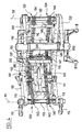
- such a system includes an arm 100 of V or L geometry articulated at one end to the chassis or fuselage and through the other end on the door 10.
- the precise geometry and the dimensions of the arm 100 depend on various parameters of which the thickness of the fuselage, the place of articulation and the kinematics sought.
- the general structure of such an arm 100 is known from those skilled in the art, will not be described in detail later.
- the arm 100 preferably carries two parallel shafts 110, 120, advantageously substantially vertical.
- the first shaft 110 is connected to the fuselage by any means appropriate. These means are referenced 112 in FIG. 4.
- the shaft 110 is free to pivot about its longitudinal axis 111 relative at the arm 100.
- the second shaft 120 is linked to the door 10 by any means suitable, for example by a set of rods 122.
- the shaft 120 is itself free of pivoting about its longitudinal axis 121 by compared to the arm 100.
- the device also comprises means ensuring a rotational connection between the two shafts 110, 120.
- these rotation link means preferably comprise at least one chain.
- the device comprises two sets of chains each in the shape of a loop, respectively upper and lower and referenced 130 and 140 in Figure 4.
- Each of the two sets of chains 130, 140 is engaged with two pinions 113, 114 and 123, 124 respectively connected to one of the two trees 110, 120 above.
- the arm 100 also carries two pairs of pinion gears 131, 132 and 141, 142 arranged to guide each set of chains 130, 140 on a wedding circuit overall V or L geometry of the arm 100.
- the shaft 110 being fixed by relative to the fuselage
- the pivotal movement of the arm 100 by relation to the fuselage causes a translation of the sets of chains 130, 140 thanks to the cooperation defined between these and the pinions 113, 114 and thence a rotation of the shaft 120 relative to the arm 100 thanks to the cooperation defined between sets of chains 130, 140 and the pinions 123, 124, adapted to hold the door 10 connected to the shaft 120 parallel to its rest position.
- each set of chains 130, 140 comprises two link sections 133, 134 and 143, 144 interconnected respectively by two parallel rods 135, 136 and 145, 146.
- the two pairs of rods 135, 136, 145, 146 are guided free sliding by vertical struts 115, 116 carried by the arm 100.
- the device according to the present invention further comprises a motor element 200 formed of a pyrotechnic jack.
- the element motor 200 is carried by the arm 100.
- the motor element 200 comprises essentially a body 210 and a rod or piston likely to be displaced relative to the body 210.
- the body 210 is connected to the arm 100, for example at the spacer 115.
- the rod or piston 220 as to she wears a solicitation organ or pusher in the shape of a crossbow referenced 250.
- the biasing member 250 is placed next to stops 137, 147 carried by one of the rods 135, 145 of each set of chains 130, 140.
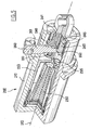
- FIG. 5 to 10 A preferred but non-limiting embodiment of the jack pyrotechnic is illustrated in Figures 5 to 10 attached.
- the pyrotechnic jack 200 houses a mass 230 of composition pyrotechnic device capable of generating a hot gas developed in a chamber between the body 210 and the piston 220 to cause the expansion of the cylinder, that is to say an outlet of the rod 220 relative to the body 210.
- the mass of composition pyrotechnic 230 may be propellant.
- the mass pyrotechnic composition 230 has a variable section, more precisely an increasing section away from its initiated face.
- the section variation of the mass of pyrotechnic composition 230 is adapted to generate an increase in the volume of gas developed proportional to the resulting increase in the room defined between the body 210 and the piston 220 to operate a constant force on the rod 220 whatever the expansion of it.
- the pyrotechnic mass 230 can be initiated by any means appropriate. It can be an electric initiator.
- the mass 230 is initiated by a initiator or mechanical striker.
- the jack pyrotechnic 200 preferably comprises two strikers 240, 245 associated respectively with springs of solicitation 241, 246, bandaged at rest. Each striker 240, 245 is placed next to a primer 250, 255.
- the initiation of the primers 250 and 255 is transmitted in a known per se to the pyrotechnic mass 230.
- the pyrotechnic jack 200 preferably comprises a locking slide 260.
- the drawer 260 provides a dual function of security. On the one hand, the drawer 260 provides a mechanical lock, at the rest, the piston 220. On the other hand, the drawer 260 ensures at rest a mechanical blocking of strikers 240 and 245.
- the lock slide 260 can be the object of many variants of embodiment. Preferably, it is mounted in translation in a direction orthogonal to the longitudinal axis 212 of the body 210.
- the drawer 260 has two sections with different straight sections: an outer section 261 of strong cross section and an inner section 262 of lower cross section.
- Body 210 has a throat longitudinal 214 (see in particular Figure 6).
- the throat 214 has a width smaller than the bulk in cross section of the outer section 261 of the drawer 260, but higher at the same space in cross section of the inner section 262.
- the outer portion 261 of the drawer 260 is placed opposite the groove 214.
- the drawer 260 connected to the rod 220 can not be moved in the throat 214.
- the slide 260 thus ensures a mechanical locking between the rod 220 and the body 210.
- the drawer 260 has a structure 263 serving as a stop strikers 240, 245 in the initial rest position of the drawer 260 tel shown in FIG. 8.
- the drawer 260 has, on the other hand, lights 264, 265 placed next to strikers 240, 245 after translation radially outwardly of the slide 260 to allow the moving the strikers 240, 245 against the primers 250, 255.
- the mass of pyrotechnic material 230, the primers 250, 255 and strikers 240, 245 are carried by the rod 220.
- all of these elements, or at least part of them of them, could be worn by the body 210.
- the driving element pyrotechnic 200 is associated with a damping element.
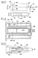
- Such a damping element 300 can be the object of numerous variants of embodiment. According to the schematized embodiment on the 11, it may be a jack having a body 310 and a piston 320 having calibrated bores 322 to allow a controlled movement of fluid on either side of the piston 320, when the rod 324 connected to the piston 320 is urged to move relative to the body 310.
- FIG. 12 shows a variant of realization that the pyrotechnic jack 200 is integrated in the rod 324 of such a damping element.
- the rod 324 has the shape of a bell and cooperates with a skirt 318 centered on the body 310 for define an outer annular chamber 326 in which the piston 320 provided with calibrated bores 322.
- the skirt 318 serves as an external body to the pyrotechnic jack.
- the piston of the pyrotechnic cylinder is also placed in the skirt 318. It houses the initiation system 240, 245 and the mass of pyrotechnic material 230.
- an elastic damping means 280 is inserted between the pyrotechnic piston 220 and the piston or rod 324 of the damper.
- FIG. 13 illustrates a variant embodiment distinguishes from FIG. 12 in that the rod or piston element 324 of the shock absorber has a line of weakness adapted to be broken during the implementation of the pyrotechnic jack 200 so to ensure a disengagement of the damping element during the implementation the pyrotechnic jack.
- the effort is exerted directly by the piston or outlet rod 220 of the cylinder pyrotechnic.
- the control of the pyrotechnic jack 200 can be provided by all appropriate means. It can be mechanical or electrical devices placed on the door thus equipped at the disposal of the staff or in the control cockpit of the aircraft.
- the rod 220 actuates the biasing member 250 and causes, via sets of chains 130, 140 the pivotal movement of the 100 arm and door.
- the entire command required for the extraction of the locking element 260 may be formed of any means appropriate, for example a handle arranged on the door and associated to a proper linkage linkage.
- the closure element or door 10 continues its inertial stroke when the abutments 137, 147 escape the pusher 250.
- the present invention offers the advantage of easily allow localized control on the door or remotely of it.
- the use of a jack-type motor element pyrotechnics offers the advantage of good storage quality in the time. It allows the realization of a totally waterproof system. In effect a pyrotechnic cylinder requires no vent, including for a return to the original position, since the pyrotechnic jack allows easy retraction of the rod 220 as soon as the gases developed have cooled.
- the present invention makes it possible to hold a wide range of temperature. It allows to offer a light and perfectly insensitive to both variations in orientation in space, electrical or electromagnetic interference, or any other type aggression, and mechanical vibration.
- the implantation of the pyrotechnic jack 200 is not limited to the aforementioned provision.
- the cylinder 200 can indeed be disposed outside of the arm.
- the cooperation between the jack 200 and the door 10 can be obtained with an interface other than a chain.
Landscapes
- Engineering & Computer Science (AREA)
- Mechanical Engineering (AREA)
- Aviation & Aerospace Engineering (AREA)
- Power-Operated Mechanisms For Wings (AREA)
- Lock And Its Accessories (AREA)
Applications Claiming Priority (2)
| Application Number | Priority Date | Filing Date | Title |
|---|---|---|---|
| FR0315002 | 2003-12-19 | ||
| FR0315002A FR2864021B1 (fr) | 2003-12-19 | 2003-12-19 | Dispositif de commande a deplacement d'un element de fermeture pour vehicule |
Publications (3)
| Publication Number | Publication Date |
|---|---|
| EP1544098A1 true EP1544098A1 (de) | 2005-06-22 |
| EP1544098A8 EP1544098A8 (de) | 2006-03-01 |
| EP1544098B1 EP1544098B1 (de) | 2008-01-02 |
Family
ID=34508714
Family Applications (1)
| Application Number | Title | Priority Date | Filing Date |
|---|---|---|---|
| EP04293001A Expired - Lifetime EP1544098B1 (de) | 2003-12-19 | 2004-12-15 | Antriebsvorrichtung zum Versetzen eines Verschlusselements für Fahrzeuge |
Country Status (6)
| Country | Link |
|---|---|
| US (1) | US7168659B2 (de) |
| EP (1) | EP1544098B1 (de) |
| BR (1) | BRPI0405618A (de) |
| CA (1) | CA2491245A1 (de) |
| DE (1) | DE602004011009D1 (de) |
| FR (1) | FR2864021B1 (de) |
Cited By (5)
| Publication number | Priority date | Publication date | Assignee | Title |
|---|---|---|---|---|
| EP2363560A1 (de) * | 2010-03-05 | 2011-09-07 | Parosha Holding B.V. | Türanordnung |
| EP2468625A3 (de) * | 2010-12-21 | 2013-10-30 | HS Products Engineering GmbH | Sicherheitseinrichtung für Luftfahrzeuge und Tür oder Klappe für ein Luftfahrzeug |
| WO2017042165A1 (fr) | 2015-09-07 | 2017-03-16 | Latecoere | Procede et systeme d'ouverture d'urgence d'une porte de secours d'aeronef |
| WO2019012027A1 (fr) | 2017-07-13 | 2019-01-17 | Innovation Contrôle Système - I.C.S. | Etui de concentration d'energie |
| CN109677583A (zh) * | 2018-12-05 | 2019-04-26 | 太原航空仪表有限公司 | 一种高精度可调节限位装置 |
Families Citing this family (17)
| Publication number | Priority date | Publication date | Assignee | Title |
|---|---|---|---|---|
| US7311169B1 (en) * | 2005-09-22 | 2007-12-25 | Ford Global Technologies, Llc | Door system for automotive vehicle |
| US7735199B2 (en) * | 2007-05-09 | 2010-06-15 | B/E Aerospace, Inc. | Aircraft door hinge assembly |
| RU2476349C2 (ru) * | 2007-05-09 | 2013-02-27 | Б/Е Аэроспейс, Инк. | Система вентиляционной двери с рычажным механизмом |
| DE102007027550A1 (de) * | 2007-06-15 | 2008-12-18 | Airbus Deutschland Gmbh | Differenzdruckgesteuerter Verriegelungsmechanismus |
| FR2975967B1 (fr) | 2011-05-31 | 2013-07-05 | Latecoere | Dispositif d'ouverture d'urgence d'une porte d'aeronef |
| EP2644495B1 (de) * | 2012-03-27 | 2015-06-17 | AIRBUS HELICOPTERS DEUTSCHLAND GmbH | Notfallöffnungssystem für eine Flugzeugkabinentür |
| CN104192293B (zh) * | 2014-09-15 | 2016-06-08 | 北京航空航天大学 | 一种薄壁式复杂曲面造型无人飞行器的设备舱门机构 |
| PL3050794T3 (pl) * | 2015-01-28 | 2017-09-29 | Airbus Helicopters Deutschland GmbH | Statek powietrzny ze składanymi do wewnątrz drzwiami tylnymi |
| CN107618652B (zh) * | 2017-09-11 | 2024-04-02 | 珠海天晴航空航天科技有限公司 | 一种无人机口盖快卸结构及顶起装置 |
| FR3084335B1 (fr) | 2018-07-24 | 2020-09-11 | Latecoere | Dispositif d'ouverture d'urgence d'une porte d'aeronef, a organe de retenue a crochet |
| FR3084333A1 (fr) | 2018-07-24 | 2020-01-31 | Latecoere | Dispositif d'ouverture d'urgence d'une porte d'aeronef, a organe de manoeuvre telescopique |
| FR3084334B1 (fr) | 2018-07-24 | 2020-09-11 | Latecoere | Dispositif d'ouverture d'urgence d'une porte d'aeronef, a organe de retenue a levier |
| DE102018121240B4 (de) * | 2018-08-30 | 2026-01-22 | Airbus Operations Gmbh | Türanordnung für ein Flugzeug und Flugzeug |
| FR3098490B1 (fr) | 2019-07-08 | 2021-07-02 | Latecoere | Dispositif d’ouverture d’urgence d’une porte d’aéronef à fil de retenue |
| US11725710B2 (en) * | 2020-06-04 | 2023-08-15 | The Boeing Company | Variable fluid damping |
| FR3113028B1 (fr) | 2020-07-30 | 2022-08-12 | Latecoere | Dispositif d’ouverture d’urgence d’une porte d’aéronef à organe de retenue périphérique |
| US20250327350A1 (en) * | 2024-04-18 | 2025-10-23 | The Boeing Company | Mechanical programming system and method for controlling the orientation of a door |
Citations (4)
| Publication number | Priority date | Publication date | Assignee | Title |
|---|---|---|---|---|
| US2924404A (en) * | 1956-07-31 | 1960-02-09 | Gen Dynamics Corp | Actuating device |
| DE4124377C1 (en) * | 1991-07-23 | 1992-12-17 | Deutsche Airbus Gmbh, 2000 Hamburg, De | Aircraft door emergency opening device - has actuator cylinder to swing door outwards and pyrotechnic device may be used |
| US5379971A (en) * | 1993-12-22 | 1995-01-10 | The Boeing Company | Emergency power system for door |
| EP0741073A1 (de) * | 1995-05-02 | 1996-11-06 | The Boeing Company | Dämpfungssystem für verschiebbare Flugzeugtür |
Family Cites Families (7)
| Publication number | Priority date | Publication date | Assignee | Title |
|---|---|---|---|---|
| US3940887A (en) * | 1974-11-18 | 1976-03-02 | Republic Industries, Inc. | Hydraulically controlled pneumatic swinging door operator |
| NL8203956A (nl) * | 1982-10-13 | 1984-05-01 | Fokker Bv | Scharniermechanisme voor een vliegtuigdeur. |
| US5180121A (en) * | 1991-05-06 | 1993-01-19 | The Boeing Company | Aircraft door hinge mechanism with selectively triggerable actuator |
| US5156359A (en) * | 1991-06-13 | 1992-10-20 | The Boeing Company | Handle assembly for an aircraft door or the like |
| US5289615A (en) * | 1991-11-08 | 1994-03-01 | The Boeing Company | Aircraft door hinge mechanism |
| FR2685741A1 (fr) * | 1991-12-31 | 1993-07-02 | Thomson Brandt Armements | Verin pyrotechnique a course amortie. |
| EP1418121A1 (de) * | 2002-11-06 | 2004-05-12 | Eaton Fluid Power GmbH | Türbetätigungssystem für Notfälle |
-
2003
- 2003-12-19 FR FR0315002A patent/FR2864021B1/fr not_active Expired - Fee Related
-
2004
- 2004-12-15 EP EP04293001A patent/EP1544098B1/de not_active Expired - Lifetime
- 2004-12-15 DE DE602004011009T patent/DE602004011009D1/de not_active Expired - Lifetime
- 2004-12-16 CA CA002491245A patent/CA2491245A1/fr not_active Abandoned
- 2004-12-17 BR BR0405618-3A patent/BRPI0405618A/pt not_active IP Right Cessation
- 2004-12-17 US US11/015,914 patent/US7168659B2/en not_active Expired - Fee Related
Patent Citations (4)
| Publication number | Priority date | Publication date | Assignee | Title |
|---|---|---|---|---|
| US2924404A (en) * | 1956-07-31 | 1960-02-09 | Gen Dynamics Corp | Actuating device |
| DE4124377C1 (en) * | 1991-07-23 | 1992-12-17 | Deutsche Airbus Gmbh, 2000 Hamburg, De | Aircraft door emergency opening device - has actuator cylinder to swing door outwards and pyrotechnic device may be used |
| US5379971A (en) * | 1993-12-22 | 1995-01-10 | The Boeing Company | Emergency power system for door |
| EP0741073A1 (de) * | 1995-05-02 | 1996-11-06 | The Boeing Company | Dämpfungssystem für verschiebbare Flugzeugtür |
Cited By (6)
| Publication number | Priority date | Publication date | Assignee | Title |
|---|---|---|---|---|
| EP2363560A1 (de) * | 2010-03-05 | 2011-09-07 | Parosha Holding B.V. | Türanordnung |
| EP2468625A3 (de) * | 2010-12-21 | 2013-10-30 | HS Products Engineering GmbH | Sicherheitseinrichtung für Luftfahrzeuge und Tür oder Klappe für ein Luftfahrzeug |
| WO2017042165A1 (fr) | 2015-09-07 | 2017-03-16 | Latecoere | Procede et systeme d'ouverture d'urgence d'une porte de secours d'aeronef |
| WO2019012027A1 (fr) | 2017-07-13 | 2019-01-17 | Innovation Contrôle Système - I.C.S. | Etui de concentration d'energie |
| CN109677583A (zh) * | 2018-12-05 | 2019-04-26 | 太原航空仪表有限公司 | 一种高精度可调节限位装置 |
| CN109677583B (zh) * | 2018-12-05 | 2022-05-17 | 太原航空仪表有限公司 | 一种可调节限位装置 |
Also Published As
| Publication number | Publication date |
|---|---|
| BRPI0405618A (pt) | 2005-08-30 |
| US7168659B2 (en) | 2007-01-30 |
| US20050178601A1 (en) | 2005-08-18 |
| EP1544098B1 (de) | 2008-01-02 |
| FR2864021A1 (fr) | 2005-06-24 |
| CA2491245A1 (fr) | 2005-06-19 |
| FR2864021B1 (fr) | 2006-05-26 |
| DE602004011009D1 (de) | 2008-02-14 |
| EP1544098A8 (de) | 2006-03-01 |
Similar Documents
| Publication | Publication Date | Title |
|---|---|---|
| EP1544098B1 (de) | Antriebsvorrichtung zum Versetzen eines Verschlusselements für Fahrzeuge | |
| EP2551199B1 (de) | Überdruck-Sperrriegel | |
| CA2222470C (fr) | Dispositif de liaison d'un inverseur de poussee a un turbomoteur | |
| EP0555123B1 (de) | Einhakenvorrichtung, mit Befestigung der Fahrwerkeinfahrverriegelung eines Flugzeuges | |
| EP1571080B1 (de) | Aufhängevorrichtung eines Flugzeugtriebwerks an einem Flügelpylon | |
| EP0296936B1 (de) | Antriebsvorrichtung zum schnellen und geregelten Trennen von zwei miteinander verbundenen Teilen | |
| CA2234436C (fr) | Dispositif de fermeture et de verrouillage des obturateurs d'un inverseur de poussee | |
| EP0357494B1 (de) | Schubumkehrvorrichtung mit Hilfsklappen für einen Strahlmotor | |
| FR2622930A1 (fr) | Capotage pour turboreacteur a double flux | |
| EP1068447B1 (de) | Antriebsgerät für eine drehbewegung zwischen zwei gelenkig verbundenen gliedern und entfaltbare struktur, insbesonders für raumfahrzeuge, mit anwendung von zumindest einem solchen gerät | |
| EP2178757B1 (de) | Triebwerksgondel mit dämpfern für halbschalen | |
| WO2009047399A1 (fr) | Nacelle equipee d'au moins une trappe de surpression | |
| FR2538777A1 (fr) | Atterrisseur pour aeronef | |
| EP2182156A1 (de) | Dämpfungsvorrichtung für Öffnungselement eines Militärfahrzeugs | |
| CA3007899A1 (fr) | Systeme d'eolienne de secours comprenant un dispositif de blocage en rotation de la turbine | |
| EP2190741B1 (de) | Triebwerksgondel mit dämpfern für halbschalen | |
| FR3062637A1 (fr) | Nacelle de turboreacteur comportant un mecanisme d'entrainement d'inverseur de poussee | |
| CA3117070A1 (fr) | Dispositif d'ouverture d'urgence d'une porte d'aeronef, a debrayage rotatif | |
| EP0657352B1 (de) | Pneumatische Auswurfvorrichtung | |
| FR2949848A1 (fr) | Dispositif d'ouverture et verrouillage d'une ailette canard. | |
| EP0336788B1 (de) | Sicherheitsventil für den Entlüftungskreislauf eines Kfz-Kraftstoffbehälters | |
| FR2712946A1 (fr) | Embrayage de véhicule automobile du type tiré et à actionnement hydraulique. | |
| FR2717859A1 (fr) | Turbomoteur à double flux équipé d'un système d'inversion de poussée et d'un dispositif de restriction du canal d'éjection des gaz froids, et dispositif de restriction équipant un tel turbomoteur. | |
| FR2616857A1 (fr) | Pyromecanisme et ses applications au deverrouillage et au cisaillage d'un organe | |
| FR2704907A1 (fr) | Système auto-bloquant de commande des portes d'inverseur de poussée d'un turboréacteur. |
Legal Events
| Date | Code | Title | Description |
|---|---|---|---|
| PUAI | Public reference made under article 153(3) epc to a published international application that has entered the european phase |
Free format text: ORIGINAL CODE: 0009012 |
|
| AK | Designated contracting states |
Kind code of ref document: A1 Designated state(s): AT BE BG CH CY CZ DE DK EE ES FI FR GB GR HU IE IS IT LI LT LU MC NL PL PT RO SE SI SK TR |
|
| AX | Request for extension of the european patent |
Extension state: AL BA HR LV MK YU |
|
| 17P | Request for examination filed |
Effective date: 20051216 |
|
| RAP1 | Party data changed (applicant data changed or rights of an application transferred) |
Owner name: ETIENNE LACROIX - TOUS ARTIFICES SA Owner name: LATECOERE |
|
| AKX | Designation fees paid |
Designated state(s): DE ES FR GB SE |
|
| GRAP | Despatch of communication of intention to grant a patent |
Free format text: ORIGINAL CODE: EPIDOSNIGR1 |
|
| RIN1 | Information on inventor provided before grant (corrected) |
Inventor name: DE RESEGUIER, JOEL Inventor name: BARICOS, JEAN Inventor name: TEXCIER, ROLAND Inventor name: VALEMBOIS, GUY Inventor name: GALVANI, ERIC |
|
| GRAS | Grant fee paid |
Free format text: ORIGINAL CODE: EPIDOSNIGR3 |
|
| GRAA | (expected) grant |
Free format text: ORIGINAL CODE: 0009210 |
|
| AK | Designated contracting states |
Kind code of ref document: B1 Designated state(s): DE ES FR GB SE |
|
| REG | Reference to a national code |
Ref country code: GB Ref legal event code: FG4D Free format text: NOT ENGLISH |
|
| REG | Reference to a national code |
Ref country code: SE Ref legal event code: TRGR |
|
| GBT | Gb: translation of ep patent filed (gb section 77(6)(a)/1977) |
Effective date: 20080118 |
|
| REF | Corresponds to: |
Ref document number: 602004011009 Country of ref document: DE Date of ref document: 20080214 Kind code of ref document: P |
|
| PG25 | Lapsed in a contracting state [announced via postgrant information from national office to epo] |
Ref country code: ES Free format text: LAPSE BECAUSE OF FAILURE TO SUBMIT A TRANSLATION OF THE DESCRIPTION OR TO PAY THE FEE WITHIN THE PRESCRIBED TIME-LIMIT Effective date: 20080413 |
|
| PLBE | No opposition filed within time limit |
Free format text: ORIGINAL CODE: 0009261 |
|
| STAA | Information on the status of an ep patent application or granted ep patent |
Free format text: STATUS: NO OPPOSITION FILED WITHIN TIME LIMIT |
|
| 26N | No opposition filed |
Effective date: 20081003 |
|
| PG25 | Lapsed in a contracting state [announced via postgrant information from national office to epo] |
Ref country code: DE Free format text: LAPSE BECAUSE OF FAILURE TO SUBMIT A TRANSLATION OF THE DESCRIPTION OR TO PAY THE FEE WITHIN THE PRESCRIBED TIME-LIMIT Effective date: 20080403 |
|
| EUG | Se: european patent has lapsed | ||
| GBPC | Gb: european patent ceased through non-payment of renewal fee |
Effective date: 20081215 |
|
| REG | Reference to a national code |
Ref country code: FR Ref legal event code: ST Effective date: 20090831 |
|
| PG25 | Lapsed in a contracting state [announced via postgrant information from national office to epo] |
Ref country code: GB Free format text: LAPSE BECAUSE OF NON-PAYMENT OF DUE FEES Effective date: 20081215 |
|
| PG25 | Lapsed in a contracting state [announced via postgrant information from national office to epo] |
Ref country code: FR Free format text: LAPSE BECAUSE OF NON-PAYMENT OF DUE FEES Effective date: 20081231 |
|
| PG25 | Lapsed in a contracting state [announced via postgrant information from national office to epo] |
Ref country code: SE Free format text: LAPSE BECAUSE OF NON-PAYMENT OF DUE FEES Effective date: 20081216 |