EP1543920A1 - Verfahren und Vorrichtung zur Prüfung einer kegeligen Fläche von ringförmigen Werkstücken - Google Patents
Verfahren und Vorrichtung zur Prüfung einer kegeligen Fläche von ringförmigen Werkstücken Download PDFInfo
- Publication number
- EP1543920A1 EP1543920A1 EP04027622A EP04027622A EP1543920A1 EP 1543920 A1 EP1543920 A1 EP 1543920A1 EP 04027622 A EP04027622 A EP 04027622A EP 04027622 A EP04027622 A EP 04027622A EP 1543920 A1 EP1543920 A1 EP 1543920A1
- Authority
- EP
- European Patent Office
- Prior art keywords
- workpiece
- centering element
- annular
- measuring device
- workpiece holder
- Prior art date
- Legal status (The legal status is an assumption and is not a legal conclusion. Google has not performed a legal analysis and makes no representation as to the accuracy of the status listed.)
- Granted
Links
- 238000000034 method Methods 0.000 title claims abstract description 11
- 238000012360 testing method Methods 0.000 claims abstract description 15
- 238000006073 displacement reaction Methods 0.000 claims description 4
- 239000011248 coating agent Substances 0.000 claims description 3
- 238000000576 coating method Methods 0.000 claims description 3
- 241000237942 Conidae Species 0.000 claims description 2
- 238000003754 machining Methods 0.000 claims description 2
- 230000008021 deposition Effects 0.000 claims 1
- 238000005259 measurement Methods 0.000 abstract description 10
- 230000005540 biological transmission Effects 0.000 description 3
- 238000004519 manufacturing process Methods 0.000 description 3
- 238000011161 development Methods 0.000 description 2
- 230000018109 developmental process Effects 0.000 description 2
- 238000011156 evaluation Methods 0.000 description 2
- 239000003302 ferromagnetic material Substances 0.000 description 2
- 238000012545 processing Methods 0.000 description 2
- 239000000523 sample Substances 0.000 description 2
- 238000006243 chemical reaction Methods 0.000 description 1
- 238000012937 correction Methods 0.000 description 1
- 230000001419 dependent effect Effects 0.000 description 1
- 238000001514 detection method Methods 0.000 description 1
- 230000001627 detrimental effect Effects 0.000 description 1
- 238000010586 diagram Methods 0.000 description 1
- 238000002474 experimental method Methods 0.000 description 1
- 238000003860 storage Methods 0.000 description 1
- 238000012549 training Methods 0.000 description 1
Images


Classifications
-
- B—PERFORMING OPERATIONS; TRANSPORTING
- B23—MACHINE TOOLS; METAL-WORKING NOT OTHERWISE PROVIDED FOR
- B23Q—DETAILS, COMPONENTS, OR ACCESSORIES FOR MACHINE TOOLS, e.g. ARRANGEMENTS FOR COPYING OR CONTROLLING; MACHINE TOOLS IN GENERAL CHARACTERISED BY THE CONSTRUCTION OF PARTICULAR DETAILS OR COMPONENTS; COMBINATIONS OR ASSOCIATIONS OF METAL-WORKING MACHINES, NOT DIRECTED TO A PARTICULAR RESULT
- B23Q3/00—Devices holding, supporting, or positioning work or tools, of a kind normally removable from the machine
- B23Q3/18—Devices holding, supporting, or positioning work or tools, of a kind normally removable from the machine for positioning only
- B23Q3/183—Centering devices
-
- B—PERFORMING OPERATIONS; TRANSPORTING
- B23—MACHINE TOOLS; METAL-WORKING NOT OTHERWISE PROVIDED FOR
- B23Q—DETAILS, COMPONENTS, OR ACCESSORIES FOR MACHINE TOOLS, e.g. ARRANGEMENTS FOR COPYING OR CONTROLLING; MACHINE TOOLS IN GENERAL CHARACTERISED BY THE CONSTRUCTION OF PARTICULAR DETAILS OR COMPONENTS; COMBINATIONS OR ASSOCIATIONS OF METAL-WORKING MACHINES, NOT DIRECTED TO A PARTICULAR RESULT
- B23Q17/00—Arrangements for observing, indicating or measuring on machine tools
- B23Q17/20—Arrangements for observing, indicating or measuring on machine tools for indicating or measuring workpiece characteristics, e.g. contour, dimension, hardness
Definitions
- the invention relates to a device for testing the concentricity of annular workpieces with an inner cone and / or outer cone according to The preamble of claim 1.
- the invention also relates to a Method for operating such a device according to claim 14.
- Measuring devices Devices and methods for testing or surveying of workpieces, in particular annular workpieces, by means of suitable Measuring devices are known per se. These measuring devices usually have a complicated and expensive portal jib, in order to be able to introduce the measuring device to the test object. moreover These are usually part of a separate device, in turn a base frame with a workpiece holder in the form of a rotary table having corresponding locking devices for the specimen.
- a further object of the invention is furthermore to provide a method of operating such a device.
- the device according to the invention for testing the Concentricity of annular workpieces with an inner cone and / or Outer cone first from one in a base frame against rotation, however axially symmetrically mounted rotationally symmetrical centering for the annular workpiece and a coaxially arranged, as well as on the base frame axially fixed, but rotatably mounted dish-shaped Workpiece holder.
- the rotationally symmetrical centering element a conical edge web, whose conical surface area to the conical surface of the annular workpiece corresponds such that due to axial Inlingerides the two mutually corresponding conical surface areas between the centering and the workpiece a positive connection can be realized, and at the centering at least one measuring device attached to the roundness measurement.
- the plate-shaped workpiece holder for receiving an annular workpiece formed with inner cone in diameter larger than the rotationally symmetric Centering element, wherein the measuring device within the of Ring-shaped workpiece enclosed space attached to the centering is.
- the plate-shaped workpiece holder for receiving a workpiece with Outside cone is formed smaller in diameter than the rotationally symmetric Centering element, in which case the measuring device outside the space enclosed by the annular workpiece on the centering element is attached.
- the measuring device is attached to the centering such that their measuring means as far as possible radially to the measured conical surface of the annular workpiece points or is guided.
- the measuring means of the measuring device by a recess radially in the edge web of the centering on the measured Convex surface of the annular workpiece point or be guided.
- the Measuring device by a non-contact a mechanical scanning or a mechanical electronic measuring device is formed.
- a non-contact Measuring device can Laserabtast pleasingen or cameras, in particular CCD cameras are used.
- the plate-shaped Workpiece holder in its edge region one or more evenly over the circumference of the same distributed holding elements for fixing the workpiece has on the surface of the workpiece holder.
- the holding elements can by electric or permanent magnets and / or by an increased frictional engagement between the surface of the Workpiece holder and the workpiece realizing surface coating be formed.
- the axial displacement of the rotationally symmetric centering by a linear drive is realized, wherein this manually, electrically, hydraulically or pneumatically operated.
- the rotatably mounted dish-shaped Workpiece holder manually or by means of a motorized drive rotatably driven.
- the lifting of the workpiece from the plate-shaped workpiece holder through the centering and the subsequent drop off again the same must be carried out at least once, but preferably several times.
- the proposed device has with regard to conventional measuring devices the significant advantage that a single production worker on-the-spot concentricity testing on the machine tool in a matter of seconds can do it yourself. Upon detection of exceedances of the permissible roundness tolerance, the worker can respond immediately and a correction on the machine, or on the tool clamping of the same which, due to the rapid reaction, is an essential Committee minimization is recorded. There is thus an immediate measurement result which is immediately taken into account in the current production Can be found. Waiting or downtime are advantageously minimized or Control posts do not have to be visited separately. Furthermore is recorded as extremely advantageous that the centering of the centering the largest possible bearing portion of the cone of the specimen, for example a synchronizer ring, detected, which also during synchronization in the transmission comes to fruition.
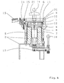
- the rotationally symmetrical centering element 4 has the Further, a conical edge web 9, the conical surface 10th corresponds to the conical surface 11 of the annular workpiece 1, that due to an axial meshing of the two corresponding to each other Cone shell surfaces 10, 11 between the centering element 4 and the workpiece 1 a positive connection can be realized by the present centering cone of the centering element 4 the largest possible bearing portion of the cone of the workpiece 1, for example, a synchronizer ring detected, which also during the Synchronizing in the transmission comes to fruition.
- the plate-shaped workpiece holder 6 for receiving or supporting the annular workpiece. 1 formed larger in diameter with an inner cone 5 in the cylindrical region as the rotationally symmetrical centering element 4, and has in her Supporting area of the workpiece one or more evenly over the circumference the same distributed holding elements 12 for fixing or fixing the Workpiece 1 on the surface of the workpiece holder 6.
- the holding elements 12 are designed as permanent magnets, however, it may also be appropriate to provide electromagnets to Workpieces 1 made of a ferromagnetic material on the flat surface to fix the workpiece holder 6.
- the holding elements 12 can also be increased by a Friction between the surface of the workpiece holder 6 and the Workpiece 1 realizing surface coating be formed (not closer ) Shown.
- the centering element 4 as the non-rotating part of the device for the intended Using the same at least one suitable measuring device 13th assigned.
- the measuring device 13 by a known per se mechanically Scanning measuring device 13 in the form of a distance measurement performing dial gauge with a measuring means 14 in the form of a rod-shaped Tasters formed and enclosed within the annular workpiece 1 Space on the centering 4 fixed but solvable by means known per se fastened mechanical fasteners such as screws.
- the attachment of the measuring device 13 on the centering element 4 is here realized so that their measuring means 14 radially to the measured conical surface 11 of the workpiece 1 is guided.
- edge web. 9 not closed, but one or more interrupted form (not shown in more detail).
- a test piece in the form of an annular workpiece. 1 with an inner cone 5 should during or after mechanical processing be checked for concentricity by means of a suitable machine tool, such is the annular workpiece 1, which is a synchronizer ring for a transmission may initially be so on the axially shifted upwards or extended centering 4 to spend that the workpiece 1 with its conical surface 11 on the corresponding conical surface 10 of the centering element 4 comes to rest (Fig. 3).
- centering element 4 is in its initial position or retracted position brought back and the workpiece 1 optimally centered on the workpiece holder 6 discontinued, where it then is fixed by means of the holding elements 12.
- a linear drive provided, which in turn manually, electrically, operated hydraulically or pneumatically.
- the required driving force of the linear drive is to be chosen so large that the tightening force, if necessary used holding elements 12 in the form of permanent or electromagnet is overcome.
- the linear drive is a manually operable eccentric lever 16 is formed, the eccentric 17 mounted with a bearing 3 in the camps Lifting rod 18 of the centering element 4 is operatively connected.
- the actual distance measurement can be performed be by a relative movement between the workpiece 1 and the attached to the rotationally fixed centering 4 measuring device 13 by rotation the workpiece holder 6 together with the workpiece 1 about the axis of rotation 19 of Workpiece holder 6 is performed (Fig. 1 and Fig. 2).
- this can also be done manually by engaging the outer circumference the workpiece holder 6 or by means of a not shown motor drive.
- the result of the measurement of the current roundness tolerance by means of the Measuring device 13 can optically (dial gauge), electronically and / or by a known measurement protocol are displayed.
- the embodiment of the device according to the invention according to FIG. 4 differs from the above essentially in that they is designed for annular workpieces 1 with an outer cone 20.
- the plate-shaped workpiece holder 6 for receiving the Workpiece 1 formed smaller in diameter than the centering element 4, that is, that the centering element 4 and workpiece holder 6 in their Arrangement are reversed within the device.
- eccentric lever 16 no longer engages in the center axis or rotation axis 19 but in the region of the outer circumference of the device on Centering 4 on.
- the measuring device 13 here in the form of a dial gauge, arranged outside of the annular workpiece 1 and the centering element 4 fixed, wherein the measuring means 14 in the form of the rod-shaped probe the recess 15 in the conical edge web 9 of the centering element 4 therethrough guided exactly perpendicular to the conical surface 11 of the workpiece 1 is.
- the relative movement between the workpiece 1 and attached to the rotationally fixed centering 4 measuring device 13 by rotation of the workpiece holder 6 together with the workpiece 1 about the axis of rotation 19 of the workpiece holder 6 performed manually by the part of Production staff at one in the axis of rotation 19 of the workpiece holder 6 is attacked with the same rotatably connected rotary handle 21.
Landscapes
- Engineering & Computer Science (AREA)
- Mechanical Engineering (AREA)
- Length Measuring Devices With Unspecified Measuring Means (AREA)
- A Measuring Device Byusing Mechanical Method (AREA)
Abstract
Description
- ein Prüfling in Form eines ringförmigen Werkstücks wird zunächst derart auf das axial nach oben verschobene beziehungsweise ausgefahrene Zentrierelement verbracht, dass das Werkstück mit seiner Kegelmantelfläche auf der korrespondierenden Kegelmantelfläche des Zentrierelements zum Liegen kommt,
- nachfolgend wird das ringförmige Werkstück durch axiale Verschiebung des Zentrierelements nach unten auf die tellerförmige Werkstückaufnahme abgesetzt und von dieser wieder derart abgehoben, dass infolge Formschluss zwischen den beiden Kegelmantelflächen eine optimale zentrische Positionierung des Werkstücks auf der Kegelmantelfläche des Zentrierelements realisiert wird,
- im Anschluss daran wird das Zentrierelement in seine Ausgangsstellung beziehungsweise eingefahrene Stellung derart zurückgefahren, dass das Werkstück optimal zentriert auf der Werkstückaufnahme zum Liegen kommt,
- schließlich wird eine Relativbewegung zwischen dem Werkstück und der am drehfesten Zentrierelement befestigten Messeinrichtung durch Drehung der Werkstückaufnahme samt Werkstück um die Drehachse der Werkstückaufnahme zur Ermittlung der aktuellen Rundheitstoleranz mittels der genannten Messeinrichtung durchgeführt.
- Fig. 1
- eine Schnittdarstellung einer erfindungsgemäßen Vorrichtung nach einer ersten Ausführungsform mit einem zentrierten und auf der Werkstückaufnahme abgelegten ringförmigen Werkstück,
- Fig. 2
- die Ansicht "A" nach Fig. 1,
- Fig. 3
- die Vorrichtung nach Fig. 1 in einem Zustand während des Abhebens eines Prüflings von der Werkstückaufnahme,
- Fig. 4
- eine Schnittdarstellung der erfindungsgemäßen Vorrichtung nach einer zweiten Ausführungsform mit einem zentrierten und auf der Werkstückaufnahme abgelegten ringförmigen Werkstück.
- 1
- Ringförmiges Werkstück
- 2
- Grundrahmen
- 3
- Lager (Zentrierelement 4)
- 4
- Zentrierelement
- 5
- Innenkegel (Werkstück 1)
- 6
- Werkstückaufnahme
- 7
- Lager (Werkstückaufnahme 6)
- 8
- Lager (Werkstückaufnahme 6)
- 9
- Randsteg
- 10
- Kegelmantelfläche (Zentrierelement 4)
- 11
- Kegelmantelfläche (Werkstück 1)
- 12
- Haltelemente
- 13
- Messeinrichtung
- 14
- Messmittel
- 15
- Aussparung
- 16
- Exzenterhebel
- 17
- Exzenter
- 18
- Hubstange
- 19
- Drehachse
- 20
- Außenkegel (Werkstück 1)
- 21
- Drehgriff
Claims (15)
- Vorrichtung zur Prüfung des Rundlaufes von ringförmigen Werkstücken (1) mit einem Innenkegel (5) und/oder Außenkegel (20), bestehend aus einem in einem Grundrahmen (2) verdrehfest, jedoch axial verschiebbar gelagerten rotationssymmetrisch ausgebildeten Zentrierelement (4) für das ringförmige Werkstück (1) und einer koaxial dazu angeordneten sowie am Grundrahmen (2) axial fest, jedoch drehbar gelagerten tellerförmigen Werkstückaufnahme (6), wobei das rotationssymmetrische Zentrierelement (4) einen kegelförmigen Randsteg (9) aufweist, dessen Kegelmantelfläche (10) zur Kegelmantelfläche (11) des ringförmigen Werkstücks (1) derart korespendiert, dass infolge eines axialen Ineinanderführens der beiden zueinander korrespondierenden Kegelmantelflächen (10, 11) zwischen dem Zentrierelement (4) und dem Werkstück (1) ein Formschluss realisierbar ist, und bei der am Zentrierelement (4) wenigstens eine Messeinrichtung (13) befestigt ist.
- Vorrichtung nach Anspruch 1, dadurch gekennzeichnet, dass die tellerförmige Werkstückaufnahme (6) zur Aufnahme eines ringförmigen Werkstücks (1) mit Innenkegel (5) im Durchmesser größer ausgebildet ist als das rotationssymmetrische Zentrierelement (4) und die Messeinrichtung (13) innerhalb des vom ringförmigen Werkstück (1) umschlossenen Raumes am Zentrierelement (4) befestigt ist.
- Vorrichtung nach Anspruch 1, dadurch gekennzeichnet, dass die tellerförmige Werkstückaufnahme (6) zur Aufnahme eines Werkstücks (1) mit Außenkegel (20) im Durchmesser kleiner ausgebildet ist als das rotationssymmetrische Zentrierelement (4) und die Messeinrichtung (13) außerhalb des vom ringförmigen Werkstück (1) umschlossenen Raumes am Zentrierelement (4) befestigt ist.
- Vorrichtung nach einem der Ansprüche 1 bis 3, dadurch gekennzeichnet, dass die Messeinrichtung (13) derart am Zentrierelement (4) befestigt ist, dass deren Messmittel (14) weitestgehend radial auf die zu messende Kegelmantelfläche (11) des ringförmigen Werkstücks (1) weist oder geführt ist.
- Vorrichtung nach Anspruch 4, dadurch gekennzeichnet, dass das Messmittel (14) der Messeinrichtung (13) durch eine Aussparung (15) im Randsteg (9) des Zentrierelements (4) hindurch radial auf die zu messende Kegelmantelfläche (11) des ringförmigen Werkstücks (1) weist beziehungsweise geführt ist.
- Vorrichtung nach einem der Ansprüche 1 bis 5, dadurch gekennzeichnet, dass die Messeinrichtung (13) durch eine berührungsfreie, eine mechanisch abtastende oder eine mechanisch elektronische Messeinrichtung (13) gebildet ist.
- Vorrichtung nach Anspruch 6, dadurch gekennzeichnet, dass die berührungsfreie Messeinrichtung (13) als Laserabtasteinrichtung oder Kamera, insbesondere CCD-Kamera, ausgebildet ist.
- Vorrichtung nach einem der Ansprüche 1 bis 7, dadurch gekennzeichnet, dass die tellerförmige Werkstückaufnahme (6) in ihrem Randbereich ein oder mehrere gleichmäßig über den Umfang derselben verteilte Haltelemente (12) zur Festlegung des Werkstücks (1) auf der Oberfläche der Werkstückaufnahme (6) aufweist.
- Vorrichtung nach Anspruch 8, dadurch gekennzeichnet, dass die Halteelemente (12) durch Elektro- oder Permanentmagnete und/oder durch eine einen erhöhten Reibschluss zwischen der Oberfläche der Werkstückaufnahme (6) und dem Werkstück (1) realisierende Oberflächenbeschichtung gebildet sind.
- Vorrichtung nach einem der Ansprüche 1 bis 9, dadurch gekennzeichnet, dass die axiale Verschiebbarkeit des rotationssymmetrischen Zentrierelements (4) mittels eines Linearantriebs bewerkstelligt ist.
- Vorrichtung nach Anspruch 10, dadurch gekennzeichnet, dass der Linearantrieb manuell, elektrisch, hydraulisch oder pneumatisch betrieben ist.
- Vorrichtung nach einem der Ansprüche 1 bis 11, dadurch gekennzeichnet, dass die drehbar gelagerte tellerförmige Werkstückaufnahme (6) manuell oder mittels eines motorischen Antriebs drehantreibbar ist.
- Vorrichtung nach einem der Ansprüche 1 bis 12, dadurch gekennzeichnet, dass dieselbe in unmittelbarer Nähe einer Werkzeugmaschine zur Bearbeitung des besagten ringförmigen Werkstücks (1) angeordnet oder integrierter Bestandteil der betreffenden Werkzeugmaschine ist.
- Verfahren zum Betreiben einer Vorrichtung zur Prüfung des Rundlaufes von ringförmigen Werkstücken (1) mit einem Innenkegel (5) und/oder Außenkegel (20) nach einem der Ansprüche 1 bis 13,
dadurch gekennzeichnet, dass ein Prüfling in Form eines ringförmigen Werkstücks (1) zunächst derart auf das axial nach oben verschobene beziehungsweise ausgefahrene Zentrierelement (4) verbracht wird, dass das Werkstück (1) mit seiner Kegelmantelfläche (11) auf der korrespondierenden Kegelmantelfläche (10) des Zentrierelements (4) zum Liegen kommt, nachfolgend das ringförmige Werkstück (1) durch axiale Verschiebung des Zentrierelements (4) nach unten auf die tellerförmige Werkstückaufnahme (6) abgesetzt und von dieser wieder abgehoben wird derart, dass infolge Formschluss zwischen den beiden Kegelmantelflächen (10, 11) eine optimale zentrische Positionierung des Werkstücks (1) auf der Kegelmantelfläche (10) des Zentrierelements (4) realisiert wird, im Anschluss daran das Zentrierelement (4) in seine Ausgangsstellung beziehungsweise eingefahrene Stellung derart zurückgefahren wird, dass das Werkstück (1) optimal zentriert auf der Werkstückaufnahme (6) zum Liegen kommt und schließlich eine Relativbewegung zwischen dem Werkstück (1) und der am drehfesten Zentrierelement (4) befestigten Messeinrichtung (13) durch Drehung der Werkstückaufnahme (6) samt Werkstück (1) um die Drehachse (19) der Werkstückaufnahme (6) zur Ermittlung der aktuellen Rundheitstoleranz mittels der Messeinrichtung (13) durchgeführt wird. - Verfahren nach Anspruch 14, dadurch gekennzeichnet, dass das Abheben des Werkstücks (1) von der tellerförmigen Werkstückaufnahme (6) mittels des Zentrierelementes (4) und nachfolgendes wieder Ablegen auf derselben wenigstens einmal, vorzugsweise jedoch mehrfach durchgeführt wird.
Applications Claiming Priority (2)
| Application Number | Priority Date | Filing Date | Title |
|---|---|---|---|
| DE10359186 | 2003-12-17 | ||
| DE2003159186 DE10359186A1 (de) | 2003-12-17 | 2003-12-17 | Vorrichtung zur Prüfung des Rundlaufs von ringförmigen Werkstücken und Verfahren zum Betreiben einer derartigen Vorrichtung |
Publications (2)
| Publication Number | Publication Date |
|---|---|
| EP1543920A1 true EP1543920A1 (de) | 2005-06-22 |
| EP1543920B1 EP1543920B1 (de) | 2006-07-05 |
Family
ID=34485432
Family Applications (1)
| Application Number | Title | Priority Date | Filing Date |
|---|---|---|---|
| EP20040027622 Expired - Lifetime EP1543920B1 (de) | 2003-12-17 | 2004-11-20 | Verfahren und Vorrichtung zur Prüfung einer kegeligen Fläche von ringförmigen Werkstücken |
Country Status (2)
| Country | Link |
|---|---|
| EP (1) | EP1543920B1 (de) |
| DE (2) | DE10359186A1 (de) |
Families Citing this family (1)
| Publication number | Priority date | Publication date | Assignee | Title |
|---|---|---|---|---|
| DE102007060871A1 (de) | 2007-12-18 | 2009-06-25 | Daimler Ag | Verfahren und Vorrichtung zum Richten einer Verzahnung |
Citations (4)
| Publication number | Priority date | Publication date | Assignee | Title |
|---|---|---|---|---|
| US4209206A (en) * | 1977-08-20 | 1980-06-24 | Rolls-Royce Limited | Rotary mounting for use especially with measuring apparatus |
| US4393698A (en) * | 1980-06-27 | 1983-07-19 | Ludwig Pietzsch | Device for measuring hollow cylinder surfaces |
| US4977682A (en) * | 1989-02-10 | 1990-12-18 | Allen Gauge & Tool Company | Hand held ovality gauge |
| US5152166A (en) * | 1990-02-12 | 1992-10-06 | Samson Ag | Method and apparatus for determining the dimensional accuracy of workpiece surfaces |
-
2003
- 2003-12-17 DE DE2003159186 patent/DE10359186A1/de not_active Withdrawn
-
2004
- 2004-11-20 EP EP20040027622 patent/EP1543920B1/de not_active Expired - Lifetime
- 2004-11-20 DE DE200450000915 patent/DE502004000915D1/de not_active Expired - Lifetime
Patent Citations (4)
| Publication number | Priority date | Publication date | Assignee | Title |
|---|---|---|---|---|
| US4209206A (en) * | 1977-08-20 | 1980-06-24 | Rolls-Royce Limited | Rotary mounting for use especially with measuring apparatus |
| US4393698A (en) * | 1980-06-27 | 1983-07-19 | Ludwig Pietzsch | Device for measuring hollow cylinder surfaces |
| US4977682A (en) * | 1989-02-10 | 1990-12-18 | Allen Gauge & Tool Company | Hand held ovality gauge |
| US5152166A (en) * | 1990-02-12 | 1992-10-06 | Samson Ag | Method and apparatus for determining the dimensional accuracy of workpiece surfaces |
Also Published As
| Publication number | Publication date |
|---|---|
| DE502004000915D1 (de) | 2006-08-17 |
| DE10359186A1 (de) | 2005-08-04 |
| EP1543920B1 (de) | 2006-07-05 |
Similar Documents
| Publication | Publication Date | Title |
|---|---|---|
| DE1932010C3 (de) | Vorrichtung zum Prüfen von Werkstücken | |
| EP0938641B1 (de) | Positionierverfahren und positioniersystem | |
| EP1554080B1 (de) | Werkzeughaltevorrichtung und verfahren zum positionieren eines werkzeugs | |
| DE10131352A1 (de) | Verfahren und Vorrichtung zum Einschrumpfen von Werkzeugen, insbesondere Zerspanungswekzeugen | |
| EP3225322B1 (de) | Verfahren und biegemaschine zur herstellung eines mehrdimensional gebogenen biegeteils | |
| EP3210709B1 (de) | Ultraschall-bearbeitungsmaschine | |
| DE69413383T2 (de) | Anordnung zum kontrollieren der dimensionen eines mechanischen stucks | |
| DE4004237A1 (de) | Verfahren und vorrichtung zur bestimmung der masshaltigkeit von werkstueckoberflaechen | |
| DE202004013916U1 (de) | Gerät zum Spannen eines Rotationswerkzeugs in einem Werkzeughalter | |
| EP1035944B1 (de) | Vorrichtung und verfahren zum korrigieren von rundlauffehlern | |
| EP1892057A2 (de) | Verfahren zur Werkzeugvermessung mit einem Messgerät sowie Messvorrichtung mit einem Messgerät zur Werkzeugvermessung | |
| DE3031616A1 (de) | Vorrichtung zur ueberpruefung von diametralen abmessungen | |
| DE102007017073A1 (de) | Vorrichtung zur Aufnahme eines im wesentlichen zylindrischen Werkstückes, insbesondere eines Schmuckringes, für die Bearbeitung mit einem Laserstrahl | |
| DE1962877C3 (de) | Vorrichtung zum Zentrieren eines Rotationskörpers | |
| EP3445528B1 (de) | Vorrichtung und verfahren zum einsetzen eines werkzeugs in eine werkzeugaufnahme | |
| EP4047340B1 (de) | Vorrichtung zur aufnahme und zum spannen eines rotorlagers und auswuchtmaschine mit einer solchen vorrichtung | |
| EP1543920B1 (de) | Verfahren und Vorrichtung zur Prüfung einer kegeligen Fläche von ringförmigen Werkstücken | |
| DE4014165A1 (de) | Verfahren zum anschluss von elektromotoren an eine pruefeinrichtung und pruefeinrichtung fuer elektromotoren zur durchfuehrung des verfahrens | |
| EP0299451B1 (de) | Vorrichtung zum Justieren des Rundlaufes der Schneidkante von Innenlochsägeblättern | |
| DE10106130C1 (de) | Verfahren zur Durchgangs- und/oder Reinheitsprüfung von Bohrungen und Vorrichtung zur Durchführung des Verfahrens | |
| DE102023130804B4 (de) | Messmaschine und Verfahren zur Positionierung eines Werkstücks in der Messmaschine | |
| DE202005006567U1 (de) | Vorrichtung zum Vermessen eines Werkzeugs | |
| DE10349241A1 (de) | Haltevorrichtung und Verfahren zum Vermessen eines Werkzeugs | |
| DE102022124823A1 (de) | Vorrichtung für die Befestigung einer mobilen Werkzeugmaschine | |
| EP3446830A1 (de) | Vorrichtung und verfahren zum vermessen einer werkzeugmaschine |
Legal Events
| Date | Code | Title | Description |
|---|---|---|---|
| PUAI | Public reference made under article 153(3) epc to a published international application that has entered the european phase |
Free format text: ORIGINAL CODE: 0009012 |
|
| AK | Designated contracting states |
Kind code of ref document: A1 Designated state(s): AT BE BG CH CY CZ DE DK EE ES FI FR GB GR HU IE IS IT LI LU MC NL PL PT RO SE SI SK TR |
|
| AX | Request for extension of the european patent |
Extension state: AL HR LT LV MK YU |
|
| 17P | Request for examination filed |
Effective date: 20050623 |
|
| GRAP | Despatch of communication of intention to grant a patent |
Free format text: ORIGINAL CODE: EPIDOSNIGR1 |
|
| AKX | Designation fees paid |
Designated state(s): DE FR HU |
|
| GRAS | Grant fee paid |
Free format text: ORIGINAL CODE: EPIDOSNIGR3 |
|
| GRAA | (expected) grant |
Free format text: ORIGINAL CODE: 0009210 |
|
| AK | Designated contracting states |
Kind code of ref document: B1 Designated state(s): DE FR HU |
|
| REF | Corresponds to: |
Ref document number: 502004000915 Country of ref document: DE Date of ref document: 20060817 Kind code of ref document: P |
|
| REG | Reference to a national code |
Ref country code: HU Ref legal event code: AG4A Ref document number: E000742 Country of ref document: HU |
|
| ET | Fr: translation filed | ||
| PLBE | No opposition filed within time limit |
Free format text: ORIGINAL CODE: 0009261 |
|
| STAA | Information on the status of an ep patent application or granted ep patent |
Free format text: STATUS: NO OPPOSITION FILED WITHIN TIME LIMIT |
|
| 26N | No opposition filed |
Effective date: 20070410 |
|
| PGFP | Annual fee paid to national office [announced via postgrant information from national office to epo] |
Ref country code: FR Payment date: 20101123 Year of fee payment: 7 |
|
| PGFP | Annual fee paid to national office [announced via postgrant information from national office to epo] |
Ref country code: DE Payment date: 20101117 Year of fee payment: 7 Ref country code: HU Payment date: 20101116 Year of fee payment: 7 |
|
| PG25 | Lapsed in a contracting state [announced via postgrant information from national office to epo] |
Ref country code: HU Free format text: LAPSE BECAUSE OF NON-PAYMENT OF DUE FEES Effective date: 20111121 |
|
| REG | Reference to a national code |
Ref country code: FR Ref legal event code: ST Effective date: 20120731 |
|
| REG | Reference to a national code |
Ref country code: DE Ref legal event code: R119 Ref document number: 502004000915 Country of ref document: DE Effective date: 20120601 |
|
| PG25 | Lapsed in a contracting state [announced via postgrant information from national office to epo] |
Ref country code: FR Free format text: LAPSE BECAUSE OF NON-PAYMENT OF DUE FEES Effective date: 20111130 |
|
| PG25 | Lapsed in a contracting state [announced via postgrant information from national office to epo] |
Ref country code: DE Free format text: LAPSE BECAUSE OF NON-PAYMENT OF DUE FEES Effective date: 20120601 |