EP1543919A1 - Machine et procédé d'usinage d'un profile de grande longueur - Google Patents
Machine et procédé d'usinage d'un profile de grande longueur Download PDFInfo
- Publication number
- EP1543919A1 EP1543919A1 EP04106511A EP04106511A EP1543919A1 EP 1543919 A1 EP1543919 A1 EP 1543919A1 EP 04106511 A EP04106511 A EP 04106511A EP 04106511 A EP04106511 A EP 04106511A EP 1543919 A1 EP1543919 A1 EP 1543919A1
- Authority
- EP
- European Patent Office
- Prior art keywords
- profile
- machining
- mandrels
- machine
- movable
- Prior art date
- Legal status (The legal status is an assumption and is not a legal conclusion. Google has not performed a legal analysis and makes no representation as to the accuracy of the status listed.)
- Granted
Links
- 238000003754 machining Methods 0.000 title claims abstract description 53
- 238000000034 method Methods 0.000 title claims abstract description 10
- 230000007246 mechanism Effects 0.000 claims abstract description 5
- 230000000717 retained effect Effects 0.000 claims description 2
- 238000006073 displacement reaction Methods 0.000 abstract description 5
- KWGRBVOPPLSCSI-WPRPVWTQSA-N (-)-ephedrine Chemical compound CN[C@@H](C)[C@H](O)C1=CC=CC=C1 KWGRBVOPPLSCSI-WPRPVWTQSA-N 0.000 description 2
- 239000000969 carrier Substances 0.000 description 1
- 230000001186 cumulative effect Effects 0.000 description 1
- 238000005553 drilling Methods 0.000 description 1
- 230000000694 effects Effects 0.000 description 1
- 239000007788 liquid Substances 0.000 description 1
- 239000000463 material Substances 0.000 description 1
- 238000003801 milling Methods 0.000 description 1
- 230000002787 reinforcement Effects 0.000 description 1
- 238000003466 welding Methods 0.000 description 1
Images


Classifications
-
- B—PERFORMING OPERATIONS; TRANSPORTING
- B23—MACHINE TOOLS; METAL-WORKING NOT OTHERWISE PROVIDED FOR
- B23Q—DETAILS, COMPONENTS, OR ACCESSORIES FOR MACHINE TOOLS, e.g. ARRANGEMENTS FOR COPYING OR CONTROLLING; MACHINE TOOLS IN GENERAL CHARACTERISED BY THE CONSTRUCTION OF PARTICULAR DETAILS OR COMPONENTS; COMBINATIONS OR ASSOCIATIONS OF METAL-WORKING MACHINES, NOT DIRECTED TO A PARTICULAR RESULT
- B23Q7/00—Arrangements for handling work specially combined with or arranged in, or specially adapted for use in connection with, machine tools, e.g. for conveying, loading, positioning, discharging, sorting
- B23Q7/04—Arrangements for handling work specially combined with or arranged in, or specially adapted for use in connection with, machine tools, e.g. for conveying, loading, positioning, discharging, sorting by means of grippers
- B23Q7/047—Arrangements for handling work specially combined with or arranged in, or specially adapted for use in connection with, machine tools, e.g. for conveying, loading, positioning, discharging, sorting by means of grippers the gripper supporting the workpiece during machining
-
- B—PERFORMING OPERATIONS; TRANSPORTING
- B23—MACHINE TOOLS; METAL-WORKING NOT OTHERWISE PROVIDED FOR
- B23Q—DETAILS, COMPONENTS, OR ACCESSORIES FOR MACHINE TOOLS, e.g. ARRANGEMENTS FOR COPYING OR CONTROLLING; MACHINE TOOLS IN GENERAL CHARACTERISED BY THE CONSTRUCTION OF PARTICULAR DETAILS OR COMPONENTS; COMBINATIONS OR ASSOCIATIONS OF METAL-WORKING MACHINES, NOT DIRECTED TO A PARTICULAR RESULT
- B23Q39/00—Metal-working machines incorporating a plurality of sub-assemblies, each capable of performing a metal-working operation
- B23Q39/02—Metal-working machines incorporating a plurality of sub-assemblies, each capable of performing a metal-working operation the sub-assemblies being capable of being brought to act at a single operating station
-
- Y—GENERAL TAGGING OF NEW TECHNOLOGICAL DEVELOPMENTS; GENERAL TAGGING OF CROSS-SECTIONAL TECHNOLOGIES SPANNING OVER SEVERAL SECTIONS OF THE IPC; TECHNICAL SUBJECTS COVERED BY FORMER USPC CROSS-REFERENCE ART COLLECTIONS [XRACs] AND DIGESTS
- Y10—TECHNICAL SUBJECTS COVERED BY FORMER USPC
- Y10T—TECHNICAL SUBJECTS COVERED BY FORMER US CLASSIFICATION
- Y10T29/00—Metal working
- Y10T29/51—Plural diverse manufacturing apparatus including means for metal shaping or assembling
- Y10T29/5176—Plural diverse manufacturing apparatus including means for metal shaping or assembling including machining means
-
- Y—GENERAL TAGGING OF NEW TECHNOLOGICAL DEVELOPMENTS; GENERAL TAGGING OF CROSS-SECTIONAL TECHNOLOGIES SPANNING OVER SEVERAL SECTIONS OF THE IPC; TECHNICAL SUBJECTS COVERED BY FORMER USPC CROSS-REFERENCE ART COLLECTIONS [XRACs] AND DIGESTS
- Y10—TECHNICAL SUBJECTS COVERED BY FORMER USPC
- Y10T—TECHNICAL SUBJECTS COVERED BY FORMER US CLASSIFICATION
- Y10T409/00—Gear cutting, milling, or planing
- Y10T409/30—Milling
- Y10T409/306216—Randomly manipulated, work supported, or work following device
- Y10T409/306384—Randomly manipulated, work supported, or work following device with work supported guide means
- Y10T409/30644—Randomly manipulated, work supported, or work following device with work supported guide means to guide tool to move in arcuate path
-
- Y—GENERAL TAGGING OF NEW TECHNOLOGICAL DEVELOPMENTS; GENERAL TAGGING OF CROSS-SECTIONAL TECHNOLOGIES SPANNING OVER SEVERAL SECTIONS OF THE IPC; TECHNICAL SUBJECTS COVERED BY FORMER USPC CROSS-REFERENCE ART COLLECTIONS [XRACs] AND DIGESTS
- Y10—TECHNICAL SUBJECTS COVERED BY FORMER USPC
- Y10T—TECHNICAL SUBJECTS COVERED BY FORMER US CLASSIFICATION
- Y10T409/00—Gear cutting, milling, or planing
- Y10T409/30—Milling
- Y10T409/306664—Milling including means to infeed rotary cutter toward work
- Y10T409/307728—Milling including means to infeed rotary cutter toward work including gantry-type cutter-carrier
-
- Y—GENERAL TAGGING OF NEW TECHNOLOGICAL DEVELOPMENTS; GENERAL TAGGING OF CROSS-SECTIONAL TECHNOLOGIES SPANNING OVER SEVERAL SECTIONS OF THE IPC; TECHNICAL SUBJECTS COVERED BY FORMER USPC CROSS-REFERENCE ART COLLECTIONS [XRACs] AND DIGESTS
- Y10—TECHNICAL SUBJECTS COVERED BY FORMER USPC
- Y10T—TECHNICAL SUBJECTS COVERED BY FORMER US CLASSIFICATION
- Y10T409/00—Gear cutting, milling, or planing
- Y10T409/30—Milling
- Y10T409/30784—Milling including means to adustably position cutter
- Y10T409/307952—Linear adjustment
- Y10T409/308288—Linear adjustment including gantry-type cutter-carrier
Definitions
- the subject of the present invention is a machine for machining a profile of great length and a corresponding process; the machining term is defined to understand here, besides the classic operations removal of material such as milling, clipping, drilling, cutting, etc., others such as marking, assembly, welding or laying fastenings like rivets, with each time a appropriate tool.
- Such profiles of great length to machining are used for example in aeronautics to form aircraft envelope reinforcements; they can be straight or curved, depending on a portion of circle or according to an evolutionary radius, particularly if must train cadres.
- Some difficulties of their machining originates from significant differences reach several millimeters) between their sides nominal and their actual ratings and their flexibility, which reveals important deformations when machining efforts are applied.
- machining may also cause or release, as the case may be, internal stresses, and therefore other deformations.
- the actual shape of the profile is therefore not determined with precision to complete machining directly, and it still varies during these machining. Final manual recalibration is necessary to bring the profile to the desired shape.
- a possibility of machining the profile consists in tightening it in several fixed mandrels, whose positions correspond to a theoretical form profile, and to bring the tools successively to places to be machined. Mandrels must be enough rigid to resist the efforts that appear. This method is difficult to implement with sufficient accuracy for the profiles of several meters.
- French patents 2,685,239 and 2,799,673 disclose two of them. They essentially comprise a pair of mandrels tightness of the profile, the distance of which is small, for isolate between them what is called a window comprising a small length of the profile, on which the machining is done.
- the mandrels have the function of place the portion of the profile included in the window to its theoretical form and keep it there for machining, the rest of the section being free.
- Such machines represent a progress sensitive. They are compact and little complicated, presenting only the pair of mandrels in more of the tool holder. They allow editing and quick disassembly of the profile; and providing sufficient rigidity to the portion of the profiles included in the window, they allow machining more accurate and faster cutting speed which improve the quality of machining and reduce deformations inflicted on the profile through attenuation vibrations and cutting forces.
- the invention was conceived according to these insufficiencies and consists, in its most general, in a machine for machining a profile of long length, including a tool holder, a pair clamping chucks, movable along the profile, and mechanisms for moving the mandrels and the tool holder, characterized in that it comprises a support the profile, comprising a stationary structure, and stationary mandrels for clamping the profile, mounted on the stationary structure by links Flexible.
- this machine takes over the design to mobile chucks from clamping the profile to define a window machining, but the mobile chucks do not move the profile, which remains stationary on the mandrels of support: they move with the tool holder while along the profile, again to place in the form theoretical portions of the profile they enclose successively, but without producing cumulative error important during their travels.
- the mandrels stationary of the support are provided with flexible links to follow the movements imposed on the profile by the moving mandrels and variations of deformations, without producing internal constraints.
- the mandrels can be moved to positions defined at the front by markers, that is, by compared to a fixed reference, which give a better accuracy compared to machines working by displacement increments that French patents described above.
- the machine then includes advantageously a stationary central column to which the stationary structure is attached, a pair of arms rotating around the column and ending respectively on the movable jaws, and a gantry belonging to the tool holder and supported by the column and by a circular rail concentric to the column.
- rotating arms can easily be controlled at angular positions determined.
- the portico continues to be well supported at both ends and can thus react to efforts important cutting.
- the stationary structure is favorably composed of arms formed of sliding portions the total length is adjustable: they can thus to fit different profiles, including different diameters and / or evolutionary radius, in the previously considered case of a column machine stationary power station, which then all these arms in a radiant disposition.
- Mobile chucks and their supports may be analogous to stationary chucks, if it is only the mobile chucks must be able to impose a specific position on the portion of the profile present in the window.
- the mandrels mobile devices are mounted on independent supports and deformable, for example also in the form of arms radiating formed of sliding portions, adapted to move the moving mandrels perpendicular to the profiled in their plane and also to make them turn around an axis perpendicular to this plane, while becoming rigid when the desired positions of the jaws we have been reached.
- the invention further relates to a method machining of a profile of great length, accomplished with a numerically controlled machine comprising a pair of mobile mandrels enclosing portions successive sections of the profile and a tool placed between movable mandrels, characterized in that the profile remains retained on a support at a position substantially fixed, and the moving chucks and the tool move along the profile over an entire length to be machined.
- the machine comprises first (FIGS. 2) a gantry 1 comprising an upper cross member 2, a central column 3 and a circular track 4 concentric.
- the crossbar 2 carries a tool holder 5 can be multi-axis and is equipped with a machining tool (in the definition at the beginning).
- the tool holder 5 can move the tool 39 into a quite a lot of machining under the gantry 1.
- the crossbar 2 is moved by rotation around the central column 3 by a pinion system and rack without play consisting of a ring gear 6 fixed to the central column 3 and a pinion 7, driven by stepper motor 8 and secured to the 2.
- the rotational movement of the crossbar 2 can be continuous or discontinuous, as we will see.
- the machine anyway includes a numerical control 9 which is only symbolized here and which can determine every moment the position and the displacement of the traverse 2.
- Mechanical encoders and indexers can be used, or other known means to follow the movement of the crossbar 2 or stop him at certain positions. Machining can be accomplished at the stop of the cross 2 or even when she moves.
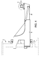
- the machine still includes a pair of arm 10 ( Figures 1, 2, 3 and 4) supported by the column 3 under the crossbar 2 and mandrel carriers 11 to their far end of column 3.
- Mandrels 11 are assigned to the clamping of the profile 12. They are equipped with positioning and clamping jaws, the layout and shape are appropriate to the profile section 12. In the case shown here ( Figure 3) of a quadrilateral section 12, you will find a fixed vertical jaw 13, a movable vertical jaw 14 opposite to the previous one, a fixed horizontal jaw 15 and a moving horizontal jaw 16 opposite to the previous, all these jaws being placed on an arch support 17.
- the jaws fixed 13 and 15 provide a positional reference by the support of the profile 12, and the movable jaws 14 and 16, actuated by hydraulic cylinders whose liquid under pressure is contained in ducts 18, rely on the other two faces of the profile 12 and complete the tightening.
- the arms 10 are composed of a portion 19 connected to the central column 3, of a portion 20 extending the previous and sliding in it and a plate 21 connected to the portion 20 by a pivot 22 vertical.
- a movement of deployment of the portion 20 in a radial direction, as well as a pivoting of the plate 22 about the vertical axis, are controlled by the numerical control 9 to adjust the radius and the direction of the portion of the section 12 that mandrel 11 encloses.
- the two arms 10 and the two mandrels 11 are controlled independently. When they both enclose the profile 12, they define a machining window between them, in which the tool 39 operates, while maintaining the profile 12 at its theoretical position at this location.
- the arms 10 are supported by a pair of circular rails 40 and 41 which is provided with the column 3. They can also be moved on said rails 40 and 41 around column 3, continuously or not, by the numerical control 9 by means similar to those of the crossing 2.
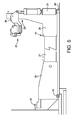
- the arms 24 comprise a fitting portion 26 connected to the central column 3, a median portion 27 extending the previous one and which is fixed to it, a end portion 28 attached to the previous and carrier of the mandrel 25 at the top of a column 29.
- the end portions 28 can be replaced easily by similar portions but presenting a column 29 of different height or mandrels 25 of different shape depending on the section of the profile or the kind of machining to perform.
- the fitting portion 26 can be turned around column 3 slipping on a pair of circular rails 42 and 43 of which it is provided.
- the middle portion 27 can be deployed from the fitting portion 26.
- the end portion 28 can rotate relative to the middle portion 27 around a vertical axis 44. All these movements are adjustments made before machining to place the mandrel 25 to the desired position and adjust to a variable curvature of the profile 12; they are arrested then by locking screws not shown.
- a anti-vibratory support 45 is inserted between the end arm 24 and the floor.
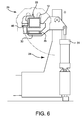
- a lever 30 articulated at the top of the Column 29 carries the mandrel 25.
- a cylinder 31 is disposed between one end of the lever 30 and a point fixed end portion 28.
- the mandrel 25 can tighten looser than mandrels 11 associated with machining: we can build it with a fixed upper jaw 32 having two lateral faces and a lower bearing surface of the section 12, and a clamping jaw 33 tilting under the effect of a hydraulic cylinder 46 to give a bit tightening and maintain the profile 12 in the impression.
- the footprint 32 is flexibly mounted (or "compliant" according to a frequent name in this technique) on the lever 30, via elastic blocks 35 which allow movements of the profile 12 in the plane of Figures 5 and 6, in radial direction and around a vertical axis.
- the support thus adapts to deformations suffered by the profile 12 during machining and avoids excessive efforts, all by maintaining a sufficient position in position, particularly in the horizontal plane, of the profile 12.
- the cylinder 31 is used to retract the mandrel 25 into lowering it, the clamping jaw 33 being raised, and clear profile 12 avoiding collision with the movable mandrels 11 during their movement on along the profile 12.
- the first can be called "by stitches and successive windows "and includes the steps following.
- the profile 12 is placed on the supports constituted by the fixed mandrels 25. One of its ends can be placed on a stop 38.
- the fixed mandrels 25 are tight.
- Mobile chucks 11 are placed at a machining start portion of the section 12 and tightened so as to delimit a first machining window.
- the portico 1 comes then move to an indexed position above the window, and the machining is carried out by the tool holder 5, the gantry 1 remaining fixed.
- one of the movable mandrels 11 is moved along the profile 12 holding on to him by a clamping pressure lesser that allows him to slide to reach the second desired position; the second mobile mandrel 11 stays tight during this time, but loosens when the first mobile chuck 11 has reached its second position and has been tightened.
- the second movable jaw 11 moves along the profile with the pressure of tightening allowing the sliding to reach its second determined position: a second window machining is then formed when the second mandrel mobile 11 has tightened, and tool 6 accomplishes this second machining after a possible displacement of the Gantry 1.
- profile 12 is free to move within the limits set out above on support chucks 25, deforming the blocks elastics 35, which absorb shape errors to the origin and other deformations of the profile. notes that the profile 12 is maintained in a plane horizontally by the fixed chucks 25, and that the movable chucks 11 (one of which is still tight) take the degree of translation and the degree of remaining rotation of the profile 12. An assembly isostatic is therefore preserved during all the machining, where it is accomplished, the profile 12 having a sufficiently flexible mounting elsewhere.
- Machining windows can be executed in any order along the profile 12.
- the second machining process envisaged is called “by bands and continuous displacement of the "windowing” .It is applied for example to train a complete face of the profile 12 over its entire length.
- One end of said profile 12 is put in support on the stop 38.
- the profile 12 is maintained in a horizontal plane by the fixed chucks 25 and at a horizontal reference fixed by the stop 38.
- the two moving arms 10 are moved simultaneously along the profile 12 at the same time as the tool 39, the clamping pressure of the mandrels 11 being set to allow slips. If the machining length exceeds the range of the tool holder 5, the crossbar 2 is moved around column 3 to the desired speed.
- An intermediate process would consist of perform successive windowing on a strip machining tool 39 being constantly moved and the moving mandrels 11 being moved when the tool 39 arrives at the end of a window.
Landscapes
- Engineering & Computer Science (AREA)
- Mechanical Engineering (AREA)
- Jigs For Machine Tools (AREA)
- Turning (AREA)
- Machine Tool Units (AREA)
- Grinding And Polishing Of Tertiary Curved Surfaces And Surfaces With Complex Shapes (AREA)
- Grinding Of Cylindrical And Plane Surfaces (AREA)
- Electrical Discharge Machining, Electrochemical Machining, And Combined Machining (AREA)
- Milling Processes (AREA)
Abstract
Description
- la figure 1 est une vue de dessus de la machine,
- la figure 2 est une vue de côté de la machine,
- la figure 3 est une vue d'un mandrin mobile de serrage,
- la figure 4 est une vue d'un bras porteur d'un des mandrins mobiles de serrage,
- la figure 5 est une vue d'un bras stationnaire porteur d'un des mandrins stationnaires de support,
- et la figure 6 est une vue d'un mandrin stationnaire et des portions voisines du bras.
Claims (11)
- Machine d'usinage d'un profilé (12) de grande longueur, comprenant un porte-outil (5), une paire de mandrins (11) de serrage du profilé, mobiles le long du profilé, et des mécanismes de déplacement des mandrins et du porte-outil, caractérisée en ce qu'elle comprend un support (23) du profilé, comprenant une structure stationnaire (24), et des mandrins (25) de serrage du profilé montés sur la structure stationnaire par des liaisons souples (35).
- Machine d'usinage d'une profilé de grande longueur selon la revendication 1, caractérisée en ce que les mandrins mobiles (11) sont aptes à être déplacés individuellement le long du profilé.
- Machine d'usinage d'un profilé de grande longueur selon la revendication 1, caractérisée en ce qu'elle comprend une colonne centrale (3) stationnaire à laquelle la structure stationnaire (24) est attachée, une paire de bras (10) tournant autour de la colonne (3) et finissant respectivement sur les mandrins mobiles (11), et un portique (1) associé au porte-outil (5) et soutenu par la colonne et par un rail circulaire (4) concentrique à la colonne.
- Machine d'usinage d'un profilé de grande longueur selon l'une quelconque des revendications 1 à 3, caractérisée en ce que la structure stationnaire est composée de bras (24) comprenant des portions coulissantes de longueur totale réglable.
- Machine d'usinage d'un profilé de grande longueur selon la revendication 4, caractérisée en ce que les bras de la structure stationnaire comportent une extrémité (28), porteuse des mandrins stationnaires (25), réglable en rotation autour d'un axe vertical.
- Machine d'usinage d'un profilé de grande longueur selon l'une quelconque des revendications 1 à 5, caractérisée en ce que les mandrins mobiles (11) sont montés sur des supports indépendants (10) et déformables de manière à pouvoir déplacer les mandrins mobiles perpendiculairement au profilé dans un plan du profilé et autour d'un axe de pivotement perpendiculaire au plan du profilé.
- Machine d'usinage d'un profilé de grande longueur selon l'une quelconque des revendications 1 à 6, caractérisée en ce que les mandrins stationnaires (25) sont munis d'un mécanisme d'escamotage.
- Machine d'usinage d'un profilé de grande longueur selon l'une quelconque des revendications précédentes, caractérisée en ce que la structure stationnaire comprend une butée (38) de mise en position d'une extrémité du profilé (12).
- Machine d'usinage d'un profilé de grande longueur selon l'une quelconque des revendications précédentes, caractérisée en ce que le porte-outil (5) est mobile indépendamment des mandrins mobiles.
- Procédé d'usinage d'un profilé de grande longueur, accompli avec une machine à commande numérique comprenant une paire de mandrins mobiles (11) enserrant des portions successives du profilé et un outil (39) placé entre les mandrins mobiles, caractérisé en ce que le profilé (12) reste retenu sur un support à une position sensiblement fixe, et les mandrins mobiles (11) et l'outil se déplacent le long du profilé sur toute une longueur à usiner.
- Procédé d'usinage d'un profilé de grande longueur selon la revendication 10, caractérisé en ce que l'outil se déplace en même temps que les mandrins mobiles (11).
Applications Claiming Priority (2)
| Application Number | Priority Date | Filing Date | Title |
|---|---|---|---|
| FR0351057A FR2863516B1 (fr) | 2003-12-15 | 2003-12-15 | Machine et procede d'usinage d'un profile de grande longueur |
| FR0351057 | 2003-12-15 |
Publications (2)
| Publication Number | Publication Date |
|---|---|
| EP1543919A1 true EP1543919A1 (fr) | 2005-06-22 |
| EP1543919B1 EP1543919B1 (fr) | 2006-08-16 |
Family
ID=34508786
Family Applications (1)
| Application Number | Title | Priority Date | Filing Date |
|---|---|---|---|
| EP04106511A Expired - Lifetime EP1543919B1 (fr) | 2003-12-15 | 2004-12-13 | Machine et procédé d'usinage d'un profile de grande longueur |
Country Status (7)
| Country | Link |
|---|---|
| US (1) | US7402009B2 (fr) |
| EP (1) | EP1543919B1 (fr) |
| AT (1) | ATE336328T1 (fr) |
| CA (1) | CA2490029C (fr) |
| DE (1) | DE602004001965T2 (fr) |
| ES (1) | ES2270288T3 (fr) |
| FR (1) | FR2863516B1 (fr) |
Families Citing this family (6)
| Publication number | Priority date | Publication date | Assignee | Title |
|---|---|---|---|---|
| ES2255386B1 (es) * | 2004-05-13 | 2007-10-01 | Loxin 2002, S.L. | Sistema mejorado de remachado automatico. |
| US8066548B1 (en) | 2006-10-19 | 2011-11-29 | Max-Tek, LLC | Multi-axes contouring machine and method of use |
| US9937549B2 (en) | 2014-07-09 | 2018-04-10 | The Boeing Company | Two-stage riveting |
| US11077517B2 (en) * | 2016-12-06 | 2021-08-03 | Concurrent Technologies Corporation | Portable friction stir welding repair tool |
| CN118989412B (zh) * | 2024-07-29 | 2025-12-30 | 江西金匠智能装备有限公司 | 一种数控龙门铣床横梁偏置式导轨的反变形加工方法 |
| CN119388235B (zh) * | 2024-11-21 | 2025-04-15 | 禾一(山东)数控机械有限公司 | 一种数控加工车床 |
Citations (3)
| Publication number | Priority date | Publication date | Assignee | Title |
|---|---|---|---|---|
| US5127139A (en) * | 1991-04-08 | 1992-07-07 | The Boeing Company | Stringer clip end effector |
| US5343603A (en) * | 1991-12-18 | 1994-09-06 | Cepede, A French Societe Anonyme Of Zone Industrielle De Saint-Laurent | Machine for machining parts from long profiles or bars |
| FR2799673A1 (fr) * | 1999-10-18 | 2001-04-20 | Michel Pioch | Dispositif d'usinage de profiles cintres |
Family Cites Families (37)
| Publication number | Priority date | Publication date | Assignee | Title |
|---|---|---|---|---|
| US1460525A (en) * | 1922-03-25 | 1923-07-03 | Campbell Wyant & Cannon Co | Circular-milling machine |
| US2408517A (en) * | 1943-09-04 | 1946-10-01 | C A Mathey | Pipe-cutting apparatus |
| US2687880A (en) * | 1950-01-16 | 1954-08-31 | Perrault Bros | Pipe beveling apparatus |
| US2705629A (en) * | 1951-08-01 | 1955-04-05 | Ford S Miller | Blow torch machine for beveling pipe |
| US2842238A (en) * | 1956-05-18 | 1958-07-08 | Albert W Shaw | Power-operated pipe cutting tool |
| US3009049A (en) * | 1958-08-13 | 1961-11-14 | Richard C Stanley | Television controlled internal pipe welding apparatus |
| DE1552887A1 (de) * | 1965-05-03 | 1971-07-22 | Gulley John M | Bearbeitungsvorrichtung |
| US3547002A (en) * | 1968-05-02 | 1970-12-15 | Lockheed Aircraft Corp | Routing machine |
| US3575364A (en) * | 1968-07-22 | 1971-04-20 | Gen Dynamics Corp | Flexible track |
| US3572669A (en) * | 1968-08-19 | 1971-03-30 | Daniel Brand | Pipe beveling machine |
| US3668971A (en) * | 1970-06-02 | 1972-06-13 | Cincinnati Milacron Inc | Method and apparatus for machining an elongated workpiece |
| US3682455A (en) * | 1970-06-05 | 1972-08-08 | Clarence W Baker | Pipe beveling machine |
| US3700223A (en) * | 1971-04-28 | 1972-10-24 | Price Co H C | Self-aligning band for beveling machine |
| US3807715A (en) * | 1972-05-18 | 1974-04-30 | Crc Crose Int Inc | Method and apparatus for heat treating welded joints |
| US3856283A (en) * | 1972-12-27 | 1974-12-24 | J Johnson | Pipe cutting and beveling tool |
| US3975003A (en) * | 1973-11-19 | 1976-08-17 | Buford Wesley E | Torch type pipe cutter |
| US4007705A (en) * | 1974-12-20 | 1977-02-15 | Dnd Corporation | Apparatus for treating a cylindrical object |
| US4091514A (en) * | 1976-04-30 | 1978-05-30 | Hydrotech International, Inc. | Subsea machine tool |
| US4148467A (en) * | 1977-12-12 | 1979-04-10 | Sargeant Eugene F | Pipe cutting and welding apparatus |
| US4297061A (en) * | 1978-05-10 | 1981-10-27 | Westinghouse Electric Corp. | Steam generator shell parting method and apparatus |
| US4460162A (en) * | 1982-01-22 | 1984-07-17 | Rusk Richard W | Torch guiding system for flame cutting of pipe |
| US4527783A (en) * | 1983-04-26 | 1985-07-09 | Grumman Aerospace Corporation | Universal contoured parts holding fixture |
| US4469310A (en) * | 1983-09-22 | 1984-09-04 | Jones Hurshel L | Automatic centering pipe beveling machine |
| US4850763A (en) * | 1988-10-03 | 1989-07-25 | The Boeing Company | Tool track for use on aircraft |
| US5189933A (en) * | 1991-04-08 | 1993-03-02 | Ricci Donato L | Clamshell mounted pipe nozzle weld milling machine with centering apparatus |
| US5615696A (en) * | 1992-07-24 | 1997-04-01 | Lawler; Oliver W. | Apparatus for treating pipe |
| US5477597A (en) * | 1993-04-14 | 1995-12-26 | Gemcor Engineering Corp. | Apparatus for positioning tooling |
| US5611130A (en) * | 1993-06-28 | 1997-03-18 | Gemcor Engineering Corp. | Multi-position rotary head apparatus |
| US5562043A (en) * | 1994-11-17 | 1996-10-08 | Valley Systems, Inc. | Rail and carriage system with magnetically adhered plastic track |
| US5685996A (en) * | 1996-05-20 | 1997-11-11 | Ricci; Donato L. | Plasma arc pipe cutting apparatus |
| US5779406A (en) * | 1996-07-17 | 1998-07-14 | Dresser Industries, Inc. | Forming a nonuniform groove in an annular bore wall |
| US6029352A (en) * | 1997-09-25 | 2000-02-29 | The Boeing Company | Wing panel assembly |
| US6098260A (en) * | 1996-12-13 | 2000-08-08 | Mcdonnell Douglas Corporation | Rivet fastening system for radial fuselage joints |
| US6267037B1 (en) * | 1999-06-22 | 2001-07-31 | Oceaneering International, Inc. | Pipeline cutting apparatus |
| DE10153807A1 (de) * | 2001-11-05 | 2003-05-28 | Emag Maschfab Gmbh | Werkzeugmaschine |
| FR2833196B1 (fr) * | 2001-12-06 | 2004-04-30 | Rouchaud | Machine d'usinage pour elements profiles longitudinaux |
| US7179027B2 (en) * | 2003-04-09 | 2007-02-20 | Bugh Roger E | Tool for positioning templates with respect to curved rail |
-
2003
- 2003-12-15 FR FR0351057A patent/FR2863516B1/fr not_active Expired - Fee Related
-
2004
- 2004-12-09 US US11/007,211 patent/US7402009B2/en not_active Expired - Fee Related
- 2004-12-10 CA CA2490029A patent/CA2490029C/fr not_active Expired - Fee Related
- 2004-12-13 ES ES04106511T patent/ES2270288T3/es not_active Expired - Lifetime
- 2004-12-13 EP EP04106511A patent/EP1543919B1/fr not_active Expired - Lifetime
- 2004-12-13 AT AT04106511T patent/ATE336328T1/de not_active IP Right Cessation
- 2004-12-13 DE DE602004001965T patent/DE602004001965T2/de not_active Expired - Lifetime
Patent Citations (3)
| Publication number | Priority date | Publication date | Assignee | Title |
|---|---|---|---|---|
| US5127139A (en) * | 1991-04-08 | 1992-07-07 | The Boeing Company | Stringer clip end effector |
| US5343603A (en) * | 1991-12-18 | 1994-09-06 | Cepede, A French Societe Anonyme Of Zone Industrielle De Saint-Laurent | Machine for machining parts from long profiles or bars |
| FR2799673A1 (fr) * | 1999-10-18 | 2001-04-20 | Michel Pioch | Dispositif d'usinage de profiles cintres |
Also Published As
| Publication number | Publication date |
|---|---|
| US20050172467A1 (en) | 2005-08-11 |
| FR2863516B1 (fr) | 2007-03-02 |
| ES2270288T3 (es) | 2007-04-01 |
| DE602004001965T2 (de) | 2007-03-15 |
| FR2863516A1 (fr) | 2005-06-17 |
| CA2490029A1 (fr) | 2005-06-15 |
| CA2490029C (fr) | 2013-01-29 |
| DE602004001965D1 (de) | 2006-09-28 |
| US7402009B2 (en) | 2008-07-22 |
| ATE336328T1 (de) | 2006-09-15 |
| EP1543919B1 (fr) | 2006-08-16 |
Similar Documents
| Publication | Publication Date | Title |
|---|---|---|
| EP0599670B1 (fr) | Fraiseuse-aléseuse à portique | |
| EP0853527B1 (fr) | Dispositif de mesure ou de controle de l'usinage d'une piece cylindrique a mouvement orbital | |
| EP1450986B1 (fr) | Machine d'usinage pour elements profiles longitudinaux | |
| CA2913103C (fr) | Dispositif de cintrage de profiles tels que des tubes | |
| EP0172105B1 (fr) | Centre d'usinage de profilés, à commande numérique | |
| WO1997037785A1 (fr) | Machine a cintrer ou a cambrer un profile, et tete de cintrage pour une telle machine | |
| EP1543919B1 (fr) | Machine et procédé d'usinage d'un profile de grande longueur | |
| EP0541689B1 (fr) | Dispositif de positionnement a l'arret pour chariot de manutention | |
| FR2811254A1 (fr) | Machine de traitement de feuilles pour la fabrication d'emballages | |
| EP0443395B1 (fr) | Machine à refouler et couper en long une bande de matière qui défile | |
| FR2501548A1 (fr) | Appareil a former les jantes | |
| JP3634185B2 (ja) | タイロッド調整装置 | |
| FR2906741A1 (fr) | Centre d'usinage de profiles de grande longueur | |
| EP0252802B1 (fr) | Machine à bois notamment pour la réalisation de cadres ou châssis de fenêtre | |
| FR2483294A1 (fr) | Procede et dispositif pour la figuration et la realisation d'enveloppes et surfaces de corps creux a conicite exterieure ou interieure | |
| FR2476059A1 (fr) | Machine et procede pour conformer le bord d'une plaque de verre | |
| FR2715339A1 (fr) | Procédé et dispositif d'assemblage d'une carrosserie automobile. | |
| EP1963066B1 (fr) | Procede d'etalonnage d'une machine de percage de verres optiques | |
| WO2008142305A2 (fr) | Machine a cintrer un profile selon deux sens de cintrage | |
| EP3458253B1 (fr) | Procédé et installation de retroussage d'une ébauche de pneumatique | |
| FR2826599A1 (fr) | Procede de percage de verres optiques, et dispositif de mise en oeuvre dudit procede | |
| BE519431A (fr) | ||
| FR2991618A1 (fr) | Installation de sciage de grumes, et procede de sciage d'une grume | |
| FR2458366A1 (fr) | Machine pour l'ecorcage de billes de bois | |
| FR2702979A1 (fr) | Machine-outil d'usinage à commande automatique pour la fabrication par usinage selon trois axes de pièces mécaniques, à partir d'une barre à plusieurs faces. |
Legal Events
| Date | Code | Title | Description |
|---|---|---|---|
| PUAI | Public reference made under article 153(3) epc to a published international application that has entered the european phase |
Free format text: ORIGINAL CODE: 0009012 |
|
| AK | Designated contracting states |
Kind code of ref document: A1 Designated state(s): AT BE BG CH CY CZ DE DK EE ES FI FR GB GR HU IE IS IT LI LT LU MC NL PL PT RO SE SI SK TR |
|
| AX | Request for extension of the european patent |
Extension state: AL BA HR LV MK YU |
|
| 17P | Request for examination filed |
Effective date: 20051222 |
|
| AKX | Designation fees paid |
Designated state(s): AT BE BG CH CY CZ DE DK EE ES FI FR GB GR HU IE IS IT LI LT LU MC NL PL PT RO SE SI SK TR |
|
| GRAP | Despatch of communication of intention to grant a patent |
Free format text: ORIGINAL CODE: EPIDOSNIGR1 |
|
| GRAS | Grant fee paid |
Free format text: ORIGINAL CODE: EPIDOSNIGR3 |
|
| GRAA | (expected) grant |
Free format text: ORIGINAL CODE: 0009210 |
|
| AK | Designated contracting states |
Kind code of ref document: B1 Designated state(s): AT BE BG CH CY CZ DE DK EE ES FI FR GB GR HU IE IS IT LI LT LU MC NL PL PT RO SE SI SK TR |
|
| PG25 | Lapsed in a contracting state [announced via postgrant information from national office to epo] |
Ref country code: SK Free format text: LAPSE BECAUSE OF FAILURE TO SUBMIT A TRANSLATION OF THE DESCRIPTION OR TO PAY THE FEE WITHIN THE PRESCRIBED TIME-LIMIT Effective date: 20060816 Ref country code: FI Free format text: LAPSE BECAUSE OF FAILURE TO SUBMIT A TRANSLATION OF THE DESCRIPTION OR TO PAY THE FEE WITHIN THE PRESCRIBED TIME-LIMIT Effective date: 20060816 Ref country code: IS Free format text: LAPSE BECAUSE OF FAILURE TO SUBMIT A TRANSLATION OF THE DESCRIPTION OR TO PAY THE FEE WITHIN THE PRESCRIBED TIME-LIMIT Effective date: 20060816 Ref country code: NL Free format text: LAPSE BECAUSE OF FAILURE TO SUBMIT A TRANSLATION OF THE DESCRIPTION OR TO PAY THE FEE WITHIN THE PRESCRIBED TIME-LIMIT Effective date: 20060816 Ref country code: LT Free format text: LAPSE BECAUSE OF FAILURE TO SUBMIT A TRANSLATION OF THE DESCRIPTION OR TO PAY THE FEE WITHIN THE PRESCRIBED TIME-LIMIT Effective date: 20060816 Ref country code: CZ Free format text: LAPSE BECAUSE OF FAILURE TO SUBMIT A TRANSLATION OF THE DESCRIPTION OR TO PAY THE FEE WITHIN THE PRESCRIBED TIME-LIMIT Effective date: 20060816 Ref country code: AT Free format text: LAPSE BECAUSE OF FAILURE TO SUBMIT A TRANSLATION OF THE DESCRIPTION OR TO PAY THE FEE WITHIN THE PRESCRIBED TIME-LIMIT Effective date: 20060816 Ref country code: IE Free format text: LAPSE BECAUSE OF FAILURE TO SUBMIT A TRANSLATION OF THE DESCRIPTION OR TO PAY THE FEE WITHIN THE PRESCRIBED TIME-LIMIT Effective date: 20060816 Ref country code: RO Free format text: LAPSE BECAUSE OF FAILURE TO SUBMIT A TRANSLATION OF THE DESCRIPTION OR TO PAY THE FEE WITHIN THE PRESCRIBED TIME-LIMIT Effective date: 20060816 Ref country code: SI Free format text: LAPSE BECAUSE OF FAILURE TO SUBMIT A TRANSLATION OF THE DESCRIPTION OR TO PAY THE FEE WITHIN THE PRESCRIBED TIME-LIMIT Effective date: 20060816 Ref country code: PL Free format text: LAPSE BECAUSE OF FAILURE TO SUBMIT A TRANSLATION OF THE DESCRIPTION OR TO PAY THE FEE WITHIN THE PRESCRIBED TIME-LIMIT Effective date: 20060816 |
|
| REG | Reference to a national code |
Ref country code: GB Ref legal event code: FG4D Free format text: NOT ENGLISH |
|
| RIN1 | Information on inventor provided before grant (corrected) |
Inventor name: HAMANN, JEAN-CHRISTOPHE Inventor name: PROVIN, MAEL |
|
| REG | Reference to a national code |
Ref country code: CH Ref legal event code: EP |
|
| REG | Reference to a national code |
Ref country code: IE Ref legal event code: FG4D Free format text: LANGUAGE OF EP DOCUMENT: FRENCH |
|
| REF | Corresponds to: |
Ref document number: 602004001965 Country of ref document: DE Date of ref document: 20060928 Kind code of ref document: P |
|
| PG25 | Lapsed in a contracting state [announced via postgrant information from national office to epo] |
Ref country code: DK Free format text: LAPSE BECAUSE OF FAILURE TO SUBMIT A TRANSLATION OF THE DESCRIPTION OR TO PAY THE FEE WITHIN THE PRESCRIBED TIME-LIMIT Effective date: 20061116 Ref country code: BG Free format text: LAPSE BECAUSE OF FAILURE TO SUBMIT A TRANSLATION OF THE DESCRIPTION OR TO PAY THE FEE WITHIN THE PRESCRIBED TIME-LIMIT Effective date: 20061116 |
|
| GBT | Gb: translation of ep patent filed (gb section 77(6)(a)/1977) |
Effective date: 20061030 |
|
| REG | Reference to a national code |
Ref country code: SE Ref legal event code: TRGR |
|
| PG25 | Lapsed in a contracting state [announced via postgrant information from national office to epo] |
Ref country code: MC Free format text: LAPSE BECAUSE OF NON-PAYMENT OF DUE FEES Effective date: 20061231 Ref country code: BE Free format text: LAPSE BECAUSE OF NON-PAYMENT OF DUE FEES Effective date: 20061231 |
|
| PG25 | Lapsed in a contracting state [announced via postgrant information from national office to epo] |
Ref country code: PT Free format text: LAPSE BECAUSE OF FAILURE TO SUBMIT A TRANSLATION OF THE DESCRIPTION OR TO PAY THE FEE WITHIN THE PRESCRIBED TIME-LIMIT Effective date: 20070116 |
|
| NLV1 | Nl: lapsed or annulled due to failure to fulfill the requirements of art. 29p and 29m of the patents act | ||
| REG | Reference to a national code |
Ref country code: IE Ref legal event code: FD4D |
|
| REG | Reference to a national code |
Ref country code: ES Ref legal event code: FG2A Ref document number: 2270288 Country of ref document: ES Kind code of ref document: T3 |
|
| PLBE | No opposition filed within time limit |
Free format text: ORIGINAL CODE: 0009261 |
|
| STAA | Information on the status of an ep patent application or granted ep patent |
Free format text: STATUS: NO OPPOSITION FILED WITHIN TIME LIMIT |
|
| 26N | No opposition filed |
Effective date: 20070518 |
|
| BERE | Be: lapsed |
Owner name: AIRBUS FRANCE Effective date: 20061231 |
|
| PG25 | Lapsed in a contracting state [announced via postgrant information from national office to epo] |
Ref country code: GR Free format text: LAPSE BECAUSE OF FAILURE TO SUBMIT A TRANSLATION OF THE DESCRIPTION OR TO PAY THE FEE WITHIN THE PRESCRIBED TIME-LIMIT Effective date: 20061117 |
|
| PG25 | Lapsed in a contracting state [announced via postgrant information from national office to epo] |
Ref country code: EE Free format text: LAPSE BECAUSE OF FAILURE TO SUBMIT A TRANSLATION OF THE DESCRIPTION OR TO PAY THE FEE WITHIN THE PRESCRIBED TIME-LIMIT Effective date: 20060816 |
|
| PG25 | Lapsed in a contracting state [announced via postgrant information from national office to epo] |
Ref country code: HU Free format text: LAPSE BECAUSE OF FAILURE TO SUBMIT A TRANSLATION OF THE DESCRIPTION OR TO PAY THE FEE WITHIN THE PRESCRIBED TIME-LIMIT Effective date: 20070217 Ref country code: TR Free format text: LAPSE BECAUSE OF FAILURE TO SUBMIT A TRANSLATION OF THE DESCRIPTION OR TO PAY THE FEE WITHIN THE PRESCRIBED TIME-LIMIT Effective date: 20060816 Ref country code: LU Free format text: LAPSE BECAUSE OF NON-PAYMENT OF DUE FEES Effective date: 20061213 |
|
| PG25 | Lapsed in a contracting state [announced via postgrant information from national office to epo] |
Ref country code: CY Free format text: LAPSE BECAUSE OF FAILURE TO SUBMIT A TRANSLATION OF THE DESCRIPTION OR TO PAY THE FEE WITHIN THE PRESCRIBED TIME-LIMIT Effective date: 20060816 |
|
| REG | Reference to a national code |
Ref country code: CH Ref legal event code: PL |
|
| PG25 | Lapsed in a contracting state [announced via postgrant information from national office to epo] |
Ref country code: CH Free format text: LAPSE BECAUSE OF NON-PAYMENT OF DUE FEES Effective date: 20081231 Ref country code: LI Free format text: LAPSE BECAUSE OF NON-PAYMENT OF DUE FEES Effective date: 20081231 |
|
| REG | Reference to a national code |
Ref country code: GB Ref legal event code: 732E Free format text: REGISTERED BETWEEN 20110721 AND 20110727 |
|
| REG | Reference to a national code |
Ref country code: FR Ref legal event code: TP Owner name: AIRBUS HOLDING, FR Effective date: 20110913 Ref country code: FR Ref legal event code: CD Owner name: AIRBUS HOLDING, FR Effective date: 20110916 Ref country code: FR Ref legal event code: CJ Effective date: 20110916 Ref country code: FR Ref legal event code: CA Effective date: 20110916 |
|
| REG | Reference to a national code |
Ref country code: ES Ref legal event code: PC2A Owner name: AIRBUS OPERATIONS SAS Effective date: 20120308 |
|
| REG | Reference to a national code |
Ref country code: DE Ref legal event code: R082 Ref document number: 602004001965 Country of ref document: DE Representative=s name: HENKEL, BREUER & PARTNER, DE |
|
| REG | Reference to a national code |
Ref country code: DE Ref legal event code: R082 Ref document number: 602004001965 Country of ref document: DE Representative=s name: PATENTANWAELTE HENKEL, BREUER & PARTNER, DE Effective date: 20120326 Ref country code: DE Ref legal event code: R081 Ref document number: 602004001965 Country of ref document: DE Owner name: AIRBUS OPERATIONS SAS, FR Free format text: FORMER OWNER: AIRBUS FRANCE, TOULOUSE, FR Effective date: 20120326 |
|
| PGFP | Annual fee paid to national office [announced via postgrant information from national office to epo] |
Ref country code: SE Payment date: 20121220 Year of fee payment: 9 |
|
| PGFP | Annual fee paid to national office [announced via postgrant information from national office to epo] |
Ref country code: ES Payment date: 20121226 Year of fee payment: 9 |
|
| REG | Reference to a national code |
Ref country code: SE Ref legal event code: EUG |
|
| PG25 | Lapsed in a contracting state [announced via postgrant information from national office to epo] |
Ref country code: SE Free format text: LAPSE BECAUSE OF NON-PAYMENT OF DUE FEES Effective date: 20131214 |
|
| REG | Reference to a national code |
Ref country code: ES Ref legal event code: FD2A Effective date: 20150504 |
|
| PG25 | Lapsed in a contracting state [announced via postgrant information from national office to epo] |
Ref country code: ES Free format text: LAPSE BECAUSE OF NON-PAYMENT OF DUE FEES Effective date: 20131214 |
|
| REG | Reference to a national code |
Ref country code: FR Ref legal event code: PLFP Year of fee payment: 12 |
|
| REG | Reference to a national code |
Ref country code: FR Ref legal event code: PLFP Year of fee payment: 13 |
|
| REG | Reference to a national code |
Ref country code: FR Ref legal event code: PLFP Year of fee payment: 14 |
|
| PGFP | Annual fee paid to national office [announced via postgrant information from national office to epo] |
Ref country code: DE Payment date: 20181210 Year of fee payment: 15 |
|
| PGFP | Annual fee paid to national office [announced via postgrant information from national office to epo] |
Ref country code: IT Payment date: 20181220 Year of fee payment: 15 |
|
| PGFP | Annual fee paid to national office [announced via postgrant information from national office to epo] |
Ref country code: FR Payment date: 20191219 Year of fee payment: 16 |
|
| PGFP | Annual fee paid to national office [announced via postgrant information from national office to epo] |
Ref country code: GB Payment date: 20191220 Year of fee payment: 16 |
|
| REG | Reference to a national code |
Ref country code: DE Ref legal event code: R119 Ref document number: 602004001965 Country of ref document: DE |
|
| PG25 | Lapsed in a contracting state [announced via postgrant information from national office to epo] |
Ref country code: IT Free format text: LAPSE BECAUSE OF NON-PAYMENT OF DUE FEES Effective date: 20191213 Ref country code: DE Free format text: LAPSE BECAUSE OF NON-PAYMENT OF DUE FEES Effective date: 20200701 |
|
| GBPC | Gb: european patent ceased through non-payment of renewal fee |
Effective date: 20201213 |
|
| PG25 | Lapsed in a contracting state [announced via postgrant information from national office to epo] |
Ref country code: FR Free format text: LAPSE BECAUSE OF NON-PAYMENT OF DUE FEES Effective date: 20201231 |
|
| PG25 | Lapsed in a contracting state [announced via postgrant information from national office to epo] |
Ref country code: GB Free format text: LAPSE BECAUSE OF NON-PAYMENT OF DUE FEES Effective date: 20201213 |