EP1543595B1 - Verfahren zur auswahl der polarisation eines laserstrahls in einem resonator - Google Patents
Verfahren zur auswahl der polarisation eines laserstrahls in einem resonator Download PDFInfo
- Publication number
- EP1543595B1 EP1543595B1 EP03798340A EP03798340A EP1543595B1 EP 1543595 B1 EP1543595 B1 EP 1543595B1 EP 03798340 A EP03798340 A EP 03798340A EP 03798340 A EP03798340 A EP 03798340A EP 1543595 B1 EP1543595 B1 EP 1543595B1
- Authority
- EP
- European Patent Office
- Prior art keywords
- cavity
- polarization
- laser
- optical
- birefringent
- Prior art date
- Legal status (The legal status is an assumption and is not a legal conclusion. Google has not performed a legal analysis and makes no representation as to the accuracy of the status listed.)
- Expired - Lifetime
Links
- 230000010287 polarization Effects 0.000 title claims abstract description 129
- 238000000034 method Methods 0.000 title claims abstract description 52
- 230000003287 optical effect Effects 0.000 claims abstract description 47
- 230000000694 effects Effects 0.000 claims abstract description 8
- 230000001939 inductive effect Effects 0.000 claims abstract description 3
- 239000000463 material Substances 0.000 claims description 37
- 239000013078 crystal Substances 0.000 claims description 22
- 230000010355 oscillation Effects 0.000 claims description 17
- 238000000926 separation method Methods 0.000 claims description 16
- 229910017502 Nd:YVO4 Inorganic materials 0.000 claims description 6
- 230000008033 biological extinction Effects 0.000 claims description 5
- 229910009372 YVO4 Inorganic materials 0.000 claims description 4
- 230000005540 biological transmission Effects 0.000 description 8
- 238000010586 diagram Methods 0.000 description 8
- 238000000576 coating method Methods 0.000 description 7
- 230000005855 radiation Effects 0.000 description 7
- 239000011149 active material Substances 0.000 description 6
- 238000004519 manufacturing process Methods 0.000 description 6
- 239000011248 coating agent Substances 0.000 description 5
- 230000009102 absorption Effects 0.000 description 4
- 238000010521 absorption reaction Methods 0.000 description 4
- 230000008901 benefit Effects 0.000 description 4
- 230000001902 propagating effect Effects 0.000 description 4
- 230000035945 sensitivity Effects 0.000 description 3
- 229910021532 Calcite Inorganic materials 0.000 description 2
- 230000009471 action Effects 0.000 description 2
- 230000008859 change Effects 0.000 description 2
- 230000005684 electric field Effects 0.000 description 2
- 230000003993 interaction Effects 0.000 description 2
- 230000005693 optoelectronics Effects 0.000 description 2
- 230000008569 process Effects 0.000 description 2
- 229910052594 sapphire Inorganic materials 0.000 description 2
- 239000010980 sapphire Substances 0.000 description 2
- 238000010187 selection method Methods 0.000 description 2
- 239000007787 solid Substances 0.000 description 2
- -1 GdVO4 Inorganic materials 0.000 description 1
- 229910003327 LiNbO3 Inorganic materials 0.000 description 1
- 230000002860 competitive effect Effects 0.000 description 1
- 238000007796 conventional method Methods 0.000 description 1
- 239000002178 crystalline material Substances 0.000 description 1
- 239000000835 fiber Substances 0.000 description 1
- 230000002045 lasting effect Effects 0.000 description 1
- 230000000737 periodic effect Effects 0.000 description 1
- 230000002250 progressing effect Effects 0.000 description 1
- 238000005086 pumping Methods 0.000 description 1
- 239000010453 quartz Substances 0.000 description 1
- 238000002310 reflectometry Methods 0.000 description 1
- 239000004065 semiconductor Substances 0.000 description 1
- VYPSYNLAJGMNEJ-UHFFFAOYSA-N silicon dioxide Inorganic materials O=[Si]=O VYPSYNLAJGMNEJ-UHFFFAOYSA-N 0.000 description 1
- 238000004513 sizing Methods 0.000 description 1
- 230000002269 spontaneous effect Effects 0.000 description 1
- 230000001629 suppression Effects 0.000 description 1
Images




Classifications
-
- H—ELECTRICITY
- H01—ELECTRIC ELEMENTS
- H01S—DEVICES USING THE PROCESS OF LIGHT AMPLIFICATION BY STIMULATED EMISSION OF RADIATION [LASER] TO AMPLIFY OR GENERATE LIGHT; DEVICES USING STIMULATED EMISSION OF ELECTROMAGNETIC RADIATION IN WAVE RANGES OTHER THAN OPTICAL
- H01S3/00—Lasers, i.e. devices using stimulated emission of electromagnetic radiation in the infrared, visible or ultraviolet wave range
- H01S3/05—Construction or shape of optical resonators; Accommodation of active medium therein; Shape of active medium
- H01S3/06—Construction or shape of active medium
- H01S3/0602—Crystal lasers or glass lasers
-
- H—ELECTRICITY
- H01—ELECTRIC ELEMENTS
- H01S—DEVICES USING THE PROCESS OF LIGHT AMPLIFICATION BY STIMULATED EMISSION OF RADIATION [LASER] TO AMPLIFY OR GENERATE LIGHT; DEVICES USING STIMULATED EMISSION OF ELECTROMAGNETIC RADIATION IN WAVE RANGES OTHER THAN OPTICAL
- H01S3/00—Lasers, i.e. devices using stimulated emission of electromagnetic radiation in the infrared, visible or ultraviolet wave range
- H01S3/05—Construction or shape of optical resonators; Accommodation of active medium therein; Shape of active medium
- H01S3/08—Construction or shape of optical resonators or components thereof
- H01S3/08004—Construction or shape of optical resonators or components thereof incorporating a dispersive element, e.g. a prism for wavelength selection
-
- H—ELECTRICITY
- H01—ELECTRIC ELEMENTS
- H01S—DEVICES USING THE PROCESS OF LIGHT AMPLIFICATION BY STIMULATED EMISSION OF RADIATION [LASER] TO AMPLIFY OR GENERATE LIGHT; DEVICES USING STIMULATED EMISSION OF ELECTROMAGNETIC RADIATION IN WAVE RANGES OTHER THAN OPTICAL
- H01S3/00—Lasers, i.e. devices using stimulated emission of electromagnetic radiation in the infrared, visible or ultraviolet wave range
- H01S3/05—Construction or shape of optical resonators; Accommodation of active medium therein; Shape of active medium
- H01S3/08—Construction or shape of optical resonators or components thereof
- H01S3/08054—Passive cavity elements acting on the polarization, e.g. a polarizer for branching or walk-off compensation
-
- H—ELECTRICITY
- H01—ELECTRIC ELEMENTS
- H01S—DEVICES USING THE PROCESS OF LIGHT AMPLIFICATION BY STIMULATED EMISSION OF RADIATION [LASER] TO AMPLIFY OR GENERATE LIGHT; DEVICES USING STIMULATED EMISSION OF ELECTROMAGNETIC RADIATION IN WAVE RANGES OTHER THAN OPTICAL
- H01S3/00—Lasers, i.e. devices using stimulated emission of electromagnetic radiation in the infrared, visible or ultraviolet wave range
- H01S3/09—Processes or apparatus for excitation, e.g. pumping
- H01S3/091—Processes or apparatus for excitation, e.g. pumping using optical pumping
- H01S3/094—Processes or apparatus for excitation, e.g. pumping using optical pumping by coherent light
- H01S3/094049—Guiding of the pump light
- H01S3/094053—Fibre coupled pump, e.g. delivering pump light using a fibre or a fibre bundle
-
- H—ELECTRICITY
- H01—ELECTRIC ELEMENTS
- H01S—DEVICES USING THE PROCESS OF LIGHT AMPLIFICATION BY STIMULATED EMISSION OF RADIATION [LASER] TO AMPLIFY OR GENERATE LIGHT; DEVICES USING STIMULATED EMISSION OF ELECTROMAGNETIC RADIATION IN WAVE RANGES OTHER THAN OPTICAL
- H01S3/00—Lasers, i.e. devices using stimulated emission of electromagnetic radiation in the infrared, visible or ultraviolet wave range
- H01S3/09—Processes or apparatus for excitation, e.g. pumping
- H01S3/091—Processes or apparatus for excitation, e.g. pumping using optical pumping
- H01S3/094—Processes or apparatus for excitation, e.g. pumping using optical pumping by coherent light
- H01S3/0941—Processes or apparatus for excitation, e.g. pumping using optical pumping by coherent light of a laser diode
- H01S3/09415—Processes or apparatus for excitation, e.g. pumping using optical pumping by coherent light of a laser diode the pumping beam being parallel to the lasing mode of the pumped medium, e.g. end-pumping
-
- H—ELECTRICITY
- H01—ELECTRIC ELEMENTS
- H01S—DEVICES USING THE PROCESS OF LIGHT AMPLIFICATION BY STIMULATED EMISSION OF RADIATION [LASER] TO AMPLIFY OR GENERATE LIGHT; DEVICES USING STIMULATED EMISSION OF ELECTROMAGNETIC RADIATION IN WAVE RANGES OTHER THAN OPTICAL
- H01S3/00—Lasers, i.e. devices using stimulated emission of electromagnetic radiation in the infrared, visible or ultraviolet wave range
- H01S3/10—Controlling the intensity, frequency, phase, polarisation or direction of the emitted radiation, e.g. switching, gating, modulating or demodulating
- H01S3/10061—Polarization control
-
- H—ELECTRICITY
- H01—ELECTRIC ELEMENTS
- H01S—DEVICES USING THE PROCESS OF LIGHT AMPLIFICATION BY STIMULATED EMISSION OF RADIATION [LASER] TO AMPLIFY OR GENERATE LIGHT; DEVICES USING STIMULATED EMISSION OF ELECTROMAGNETIC RADIATION IN WAVE RANGES OTHER THAN OPTICAL
- H01S3/00—Lasers, i.e. devices using stimulated emission of electromagnetic radiation in the infrared, visible or ultraviolet wave range
- H01S3/10—Controlling the intensity, frequency, phase, polarisation or direction of the emitted radiation, e.g. switching, gating, modulating or demodulating
- H01S3/105—Controlling the intensity, frequency, phase, polarisation or direction of the emitted radiation, e.g. switching, gating, modulating or demodulating by controlling the mutual position or the reflecting properties of the reflectors of the cavity, e.g. by controlling the cavity length
-
- H—ELECTRICITY
- H01—ELECTRIC ELEMENTS
- H01S—DEVICES USING THE PROCESS OF LIGHT AMPLIFICATION BY STIMULATED EMISSION OF RADIATION [LASER] TO AMPLIFY OR GENERATE LIGHT; DEVICES USING STIMULATED EMISSION OF ELECTROMAGNETIC RADIATION IN WAVE RANGES OTHER THAN OPTICAL
- H01S3/00—Lasers, i.e. devices using stimulated emission of electromagnetic radiation in the infrared, visible or ultraviolet wave range
- H01S3/10—Controlling the intensity, frequency, phase, polarisation or direction of the emitted radiation, e.g. switching, gating, modulating or demodulating
- H01S3/106—Controlling the intensity, frequency, phase, polarisation or direction of the emitted radiation, e.g. switching, gating, modulating or demodulating by controlling devices placed within the cavity
- H01S3/107—Controlling the intensity, frequency, phase, polarisation or direction of the emitted radiation, e.g. switching, gating, modulating or demodulating by controlling devices placed within the cavity using electro-optic devices, e.g. exhibiting Pockels or Kerr effect
- H01S3/1075—Controlling the intensity, frequency, phase, polarisation or direction of the emitted radiation, e.g. switching, gating, modulating or demodulating by controlling devices placed within the cavity using electro-optic devices, e.g. exhibiting Pockels or Kerr effect for optical deflection
-
- H—ELECTRICITY
- H01—ELECTRIC ELEMENTS
- H01S—DEVICES USING THE PROCESS OF LIGHT AMPLIFICATION BY STIMULATED EMISSION OF RADIATION [LASER] TO AMPLIFY OR GENERATE LIGHT; DEVICES USING STIMULATED EMISSION OF ELECTROMAGNETIC RADIATION IN WAVE RANGES OTHER THAN OPTICAL
- H01S3/00—Lasers, i.e. devices using stimulated emission of electromagnetic radiation in the infrared, visible or ultraviolet wave range
- H01S3/14—Lasers, i.e. devices using stimulated emission of electromagnetic radiation in the infrared, visible or ultraviolet wave range characterised by the material used as the active medium
- H01S3/16—Solid materials
- H01S3/163—Solid materials characterised by a crystal matrix
- H01S3/1671—Solid materials characterised by a crystal matrix vanadate, niobate, tantalate
- H01S3/1673—YVO4 [YVO]
Definitions
- the present invention relates to a method for selecting the polarization of the laser beam inside a laser cavity, which provides generation of a laser beam inside said resonant laser cavity, comprising one or more birefringent optical media.
- a laser cavity which provides generation of a laser beam inside said resonant laser cavity, comprising one or more birefringent optical media.
- the polarization state of the laser light in fact, is particularly important in some applications of laser-matter interaction, such as non linear processes for generating higher harmonics or for parametric generation; in most cases, where the use of a polarized laser beam is required, it is convenient to select the polarization inside the oscillator rather than outside it.
- the external selection of the polarization entails a halving of the power available, whereas the inner selection will cause much minor losses: in this event, in fact, the active element in the cavity can use all of its own gain to the advantage of the polarization whose oscillation is allowed.
- the electro-optical Q-switching modulator pertains to this category: since the polarization of the light crossing the modulator is altered by switching the modulator voltage, the Q-switching effect (i.e. modulation of the cavity losses) is reached causing the cavity to oscillate without losses on a well precise polarization, and do not oscillate on the orthogonal polarization (i.e. having high losses) due to a selection device. Modulation methods of the cavity losses through a polarization-selective element in the resonator may be employed for the so-called "mode-locking" operating mode to generate laser pulses lasting less than a nanosecond.
- selection of the oscillating polarization occurs by means of optical elements causing a highly precise linear polarization (selection of an elliptic polarization is possible but generally not very useful).
- the common operating concept of these elements is based on the introduction of different losses for the light oscillating in the resonator on one or the other linear polarization.
- polarizer devices utilize Fresnel transmission and reflection properties for surfaces inclined at the Brewster angle; as well known, when an unpolarized laser beam impinges on an optically dense plate (refractive index n) at an angle of incidence (measured with respect to the normal to the plate plane) equal to Brewster angle (which depends on the refractive index) the polarized beam component in the plane parallel to the Brewster angle is transmitted without losses, whereas the perpendicular component has power losses due to reflection depending on the refractive index n.
- n optically dense plate
- Brewster angle which depends on the refractive index
- dielectric film polarizers (Brewster angle and 45° angle) belong to this category.
- polarizers operate according to the birefringence principle through the angular separation of the main polarization components.
- Such devices are e.g. Glan-Taylor, Glan-Thompson, Nicol, Wollaston and Rochon prisms, which consist of two calcite or calcite and quartz elements either stuck together or air-spaced.
- this frame it is the main object of the present invention to provide a method for selecting the polarization of the laser beam inside a laser cavity, which is suitable for use in apparatuses with a high average power, operating in Q-switching or Mode-Locking regime, ensuring high performances and, in particular, a high transmission contrast.
- a further object of the present invention is to provide a method for selecting the polarization of the laser beam inside a laser cavity, operating in Q-switching or Mode-Locking regime, which involves negligible absorption or, in general, irrelevant laser light losses when in use in a cavity with a high average power.
- a further object of the present invention is to provide a method for selecting the polarization of the laser beam inside a laser cavity, operating in Q-switching or Mode-Locking regime, which has low manufacturing costs and easy operation.
- the inventive idea of the present invention consists substantially of a method for selecting the polarization of the oscillating laser beam inside a discrete-elements solid state laser cavity, which uses the birefringent property of an optical element inside the laser resonator and operates by means of an angular selectivity phenomenon in the alignment of the resonator itself.
- birefringent material any medium with optical anisotropy or a finite difference between the values of the refractive indexes measured along various directions inside the medium, said anisotropy being natural or induced by any external actions; interest is put in the materials having transparency at one or more of the laser wavelengths of the laser cavity where polarized oscillation is desired.
- the value of the refractive index pertaining to the light of a determined wavelength and polarized according to a precise direction inside the anisotropic material can be defined for each one of these materials, using e.g. Sellmeier's approximate equations of the material.
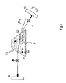
- Figure 1 is representing a TEM (Transversal Electro-Magnetic) laser beam 1, with generic polarization.
- Said laser beam 1 propagates inside an anisotropic material 9 along one of its main polarization axes; the polarization components 2 and 3 of the laser beam 1 lay in a plane perpendicular to its propagation direction and in said section of the anisotropic material 9 it is possible, as well known according to the methods of the classic optics, to define an ellipsoid of the refractive indexes to which the polarization components are subject during propagation.
- Two main axes of said ellipsoid can be defined with the two relevant values, maximum and minimum, of the refractive index; for the purposes of the method of the present invention, both maximum and minimum values should not coincide; it is also possible to separate the polarization of the laser beam 1 in two components oriented along the two main axes, i.e. the above ordinary component 2 associated to an ordinary refractive index n o and the extraordinary component 3 associated to an extraordinary refractive index n e .
- the different refractive index causes a mutual phase difference of said polarization components 2 and 3 as they further progress in the anisotropic medium 9.
- the laser beam 1 While progressing in the anisotropic medium 9, the laser beam 1 meets a face 22, where by face an optically polished surface is intended, which is crossed or hit by the output laser beam 1 from the anisotropic birefringent medium 9 towards a second medium 4, in this case represented by air, for easiness of example.
- a second medium 4 in this case represented by air, for easiness of example.
- the angular separation is at its maximum when one of the main directions, n o (ordinary) or n e (extraordinary), lays in the plane in which the angle between the normal to the interface and the propagation direction is defined, and in the event of a plane interface, the other one lays in the plane of the interface.
- Figure 2 a basic diagram illustrates the method according to the present invention. Therefore, Figure 2 is representing a resonant cavity 20 or ideal resonator, delimited by a mirror 8 placed on a first face 31 of the birefringent anisotropic material 9 and by a second mirror 10 in the air at a pre-selected distance from the anisotropic material 9.
- the anisotropic material 9 is contained in the resonant cavity 20 delimited by the two mirrors 8 and 10.
- Both the position and orientation of the first mirror 8 constrain the resonance direction of the cavity 20 in a first direction 11 exactly perpendicular to the plane of said mirror 8.
- the anisotropic medium 9 has optical anisotropy in the plane perpendicular to such a direction 11, while a second face 32 of the anisotropic material 9, forming the interface with the air 4 is inclined by an angle ⁇ i with respect to such a direction 11.
- the ideal resonant cavity 20 so delimited has two different configurations corresponding to two resonance conditions upon changing the orientation of the mirror in the air 10: a first condition in which the position of the mirror in the air 10 is apt to reflect the ordinary polarization component 6 along an optical path towards the face 32, so that inside the anisotropic material 9 said component 6 will be aligned along the direction 11; a second condition in which the position of the mirror 10 is apt to operate such a reflection for the extraordinary polarization component 7.
- the necessary condition of the method according to the present invention is to have an interfacing surface inside the cavity 20, namely the second face 32, between an optical anisotropic material 9 and another optical medium, such as the air in the example, crossed by the laser beam 1 generated in the cavity, said interfacing surface being deliberately non perpendicular to the propagation direction 11 of said laser beam 1.
- the method depicted in Figure 2 can be easily applied to a real laser cavity by evaluating an appropriate sensitivity parameter for the misalignment of the cavity 20 itself, which can be defined as the inverse of the minimum deviation angle of a mirror (or other optical element of the cavity) from its perfect optical alignment, such to cause the extinction of the laser oscillation. See Figure 7 in this connection, as better detailed in the following description.
- Said sensitivity parameter not only depends on the optical design of the resonant cavity but also on the laser gain of the active medium and on the total losses of the resonator when perfectly aligned. Once this angle is calculated relatively to the polarization-selecting interface, a perfect polarization selection will be obtained with the angular separation between the two components equalling at least twice the extinction angle. On the contrary, when the angular separation is below this value, oscillation of both the polarization components may occur to a higher or lesser amount according to the laser properties of the material associated to the two separate components.
- the cavity 20, where the ordinary axis "o” coincides with the crystallographic axis "c” of the crystal forming the anisotropic medium 9 and the extraordinary axis “e” coincides with the crystallographic axis "a” of the medium 9, consists of a Nd:YVO 4 a-cut laser crystal, manufactured according to the scheme of an active birefringent mirror, as further described.
- This laser crystal has a 4x4 mm 2 square section along the crystallographic directions "a” and "c", and a 7 mm length along the other longitudinal axis, "a”.
- the first face 31 of the crystal, plane and perpendicular to the longitudinal axis "a" has a high reflecting dielectric coating which make it highly reflecting (reflectivity R>99.5%) at the laser wavelength (in this case, 1064nm) and non reflecting (R ⁇ 5%) to the pumping wavelength (in this case, 808nm), thus forming the mirror 8.
- the second face 32 is a plane face inclined with respect to the first face 31, laying the "a"-axis transversally in the plane of the face 32 itself to form an angle of about 1 degree between the "c"-axis and the projection of the latter on the face 32 itself.
- This second face 32 has a high transmission dielectric coating that makes it non reflecting (transmission T>99.8%) at the wavelength of the laser beam 1.
- the mirror 10 At about 6cm distance from the second face 32 is placed the mirror 10, a plane output coupler mirror, with 20% transmission at 1064nm; the mirror 10 is located on a mechanical mount, not shown, with micrometric angular adjustment around two main axes oriented as "a" and "c” in the laser crystal.
- the laser crystal is longitudinally-pumped with a fibre-coupled semiconductor laser, supplying over 20W optical power at 808nm.
- Figure 6 shows the output power trend depending on the pump power for the two different polarizations ("a” and "c") selected with the method according to the present invention; it is highlighted how, with the same working parameters of the resonator, the laser features of the two polarizations are different due to their different laser properties, in particular the stimulated emission cross-sections pertaining to the two crystallographic axes "a” and “c” of Nd:YVO 4 .
- Figure 7 shows (black dots) the trend of the output power versus orientation angle of the output mirror 10 (rotated around the direction "a") at a fixed pump power of about 18W.
- the two angular resonant zones of the cavity (bell curves), one for polarization "a” and the other for polarization "c", can be clearly noticed as well as the misalignment tolerance with about 18W of the pump power absorbed in the laser crystal.
- the two resonance peaks are angularly separated by about 3.7 mrad, in very good agreement with the value of 3.63 mrad calculated for an inclination angle of 1 degree of the second face, assuming the values of 2.1652 and 1.9573 calculated at 1064nm for n e and n o , respectively.
- the laser oscillation does not totally extinguish in going over from one polarization to the other (having a mixed-polarization residue of about 4W); however, near the two resonance peaks, the polarization degree of the output radiation is better than 50:1; this is due to a competitive phenomenon between the two polarizations in exploiting the laser gain: the resonant polarization having less losses in the oscillation, deprives the other one of the gain required for the oscillation.
- the graph also suggests how increasing the angle between the two faces to about 2 degrees, the angular separation will double, ensuring total extinction of the laser action in the angular zone between the two resonance directions.
- FIG. 4 is illustrating an embodiment providing the use of an active material 9' in the resonant cavity 20, which has optical isotropy with respect to the cavity propagation axis 11, obviously emitting unpolarized laser light.
- selection of the polarization can be obtained introducing in the cavity 20 a birefringent wedge-shaped element 12 with two faces 41 and 42, both of them inclined (alternatively, only one of them inclined) with respect to the direction 11 of the mode propagation in the resonator 20 and one face inclined with respect to the other.
- the birefringent element 12 is preferably obtained with the extraordinary main axis of the material laying in the plane of the one face inclined with respect to the direction of the beam propagation, perpendicular to such a direction (i.e. perpendicular to the incidence plane) so as to maximize the angular separation effect provided by the double refraction to the interface (or interfaces) between the birefringent wedge element 12 and the air.
- both faces are inclined with respect to the laser beam, the first face 41 separates the polarizations angularly due to double refraction, whereas the second face 42 enhances the angular separation.
- the faces 41 and 42 crossed by the laser radiation have a dielectric anti-reflection coating for the laser wavelength, at the predetermined incidence angle.
- Preferred materials for the element may be GdVO 4 , YVO 4 or sapphire, cut for inner light propagation along the direction of maximum index anisotropy for the transverse components of the polarization; in the instance of GdVO 4 and YVO 4 , propagation in the material will preferably occur along one of the crystallographic axes "a", fully utilizing the strong index difference between the perpendicular axis "a” and "c"; these materials should be considered preferable for their very good transparency, strong bi-refringence, high average refractive index, high damaging threshold, easy manufacturing of antireflection dielectric coatings, wide market availability and low cost.
- the birefringent element with non parallel faces may be used to operate as a cavity mirror 14, with a face 51 facing inside the cavity 20 fitted with an appropriate antireflection dielectric coating, and the face 52 outside the cavity fitted with a dielectric coating making it totally or partially reflecting at the cavity laser wavelength (or wavelengths), thus defining a "bi-refringent mirror"; in this embodiment, only the face 51 inside the cavity operates a separation of the polarizations, whereas the mirror-machined face 52, appropriately aligned, performs the selection of one or the other polarization component.
- the active material may have non parallel faces, such as in the form of a wedge, as suggested above; to this effect, the active material operates an angular separation of the polarizations, whereas an outer optics, such as the mirror 10, for a non limiting example, performs the resonance selection of one of the polarizations.
- a possible embodiment according to this example as illustrated in Figure 5 has the birefringent laser material 9 in the form of a wedge 13 crossed by the laser beam 1; the faces 61 and 62 being crossed have antireflection dielectric coatings appropriate for the oscillating wavelength and for the predetermined incidence angle.
- the laser crystal forming the anisotropic material 9 is cut with the face 31 perpendicular to the propagation axis, which has a maximum bi-refringence for the transverse polarization components of the laser beam, and with the face 32 inclined with respect to the first one, the plane of such a face 32 containing one of the main axis of the index ellipsoid, in order to maximize the selection effect.
- the first face is coated with dielectric layers forming the cavity mirror 8
- the second face 32 is coated with antireflection dielectric layers for the laser wavelength at the incidence angle defined by the geometry of the element.
- the non linear crystal in a laser cavity containing a non linear crystal for altering the cavity frequency, may be cut with non parallel faces, such as in the form of a wedge, analogously to Figure 4 , where the birefringent element 12 may be the non linear crystal and operate as the separator of the oscillating polarization.
- the faces of the non linear crystal may receive an appropriate non reflecting (or reflecting) dielectric treatment to one or more laser wavelengths in the cavity.
- the modulator element or elements may appropriately have non parallel faces (such as in the form of a wedge), as described in the previous embodiments, analogously to Figure 4 , where the birefringent element 12 may be the modulator crystal, in order to perform separation of the main polarizations, whereas selection is performed by one of the mirrors or other optical element forming the cavity.
- an optical modulator typically for Q-switching or mode-locking
- the modulator element or elements may appropriately have non parallel faces (such as in the form of a wedge), as described in the previous embodiments, analogously to Figure 4 , where the birefringent element 12 may be the modulator crystal, in order to perform separation of the main polarizations, whereas selection is performed by one of the mirrors or other optical element forming the cavity.
- the selection of the beam polarization inside a laser cavity is useful, first of all, because it allows the choice of one or more optical properties of the output beam tied to its polarization state; however, selection of the polarization state of the laser beam is also utilized for inducing desired modulation effects of the cavity losses. If a laser resonator, in fact, contains an element for selecting the polarization state of the beam, that resonator is characterized by irrelevant or anyway very small losses for a laser beam in that determined polarization state only; any optical effect allowing a change of the polarization state of the beam propagating in the cavity (such as rotation of a linear polarization) cannot but increase the typical loss level of the above cavity.
- the polarization selection method is such to allow oscillation of a determined polarization state (as the subject method) and at the same time prevent oscillation of any laser beam in an orthogonal polarization state, then the loss level that can be introduced through the switching of the polarization to the orthogonal state in the cavity may cause the suppression of the laser oscillation; in these cases, a controlled effect of polarization switching of the laser beam propagating in the cavity would allow going from a low loss situation (maximum output power) to a maximum loss situation (nil output power); this condition is essential for the operation of laser cavities in Q-Switching regime.
- a non limiting example of a Q-Switching operating laser cavity is described in the following, in which the losses required (modulable) are obtained using the polarization selection of the method according to the present invention.
- an electro-optical Q-switching modulator 33 consisting typically of one or more crystals apt to rotate the polarization of the laser beam due to the electro-optical effect upon changing electric field applied to the crystal/s, is inserted between the active medium 9 and the mirror 10, in a position that maximizes the efficiency of the resonator (getting maximum output power when the modulator is off, i.e. subject to a nil electric field).
- the cavity can operate with irrelevant losses.
- Applying the appropriate " ⁇ /4" voltage to the modulator the latter rotates the beam polarization by 90 degrees when the laser beam travels from the crystal 9 to the mirror 10 and back again to the crystal 9. Since the resonator is not aligned for the polarization of the beam going back to the crystal 9, the laser will totally extinguish. Alternating the control voltage, the laser operates in perfect Q-switching regime, without having to use the conventional polarizer element normally utilized in the prior art.
- the advantage of the present method for obtaining Q-Switching operating cavities is important, since it eliminates the conventional polarizer element normally considered critical in high gain lasers; in fact, manufacture of polarizers with a high extinction grade for the polarization to be suppressed, irrelevant losses for the transmitted polarization and a high resistance to optical damage, represents an exceptional or, in some instances, impossible feat.
- the method for selecting the polarization of the laser beam inside a laser cavity allows choosing one or the other polarization component simply depending on the re-alignment of the resonator.
- separation of the polarizations and selection of the oscillating polarization are two independent processes, obtainable, at the limit, with just one birefringent optical element and, above all, when compared to the conventional methods the selection depends exclusively on the optical alignment of the resonator.
- the proposed method is based on creating different resonance conditions of the same oscillator, each one of them selectable through the optical alignment of the latter.
- birefringent materials suitable for practical implementation of the method for selecting the polarization of the laser beam inside a laser cavity according to the present invention are already normally used inside laser cavities and have irrelevant absorption and losses for the oscillating radiation in the resonator.
- the method for selecting the polarization of the laser beam inside a laser cavity according to the present invention can be easily extended from ideal models to a real laser cavity, by evaluating an appropriate sensitivity parameter for the misalignment of the cavity itself; when sizing a real device according to the present method, this parameter is used for controlling the oscillation of one or both the polarization components, in a higher or minor quantity according to the laser properties of the material associated to the two separate components.
Landscapes
- Physics & Mathematics (AREA)
- Electromagnetism (AREA)
- Engineering & Computer Science (AREA)
- Plasma & Fusion (AREA)
- Optics & Photonics (AREA)
- Chemical & Material Sciences (AREA)
- Crystallography & Structural Chemistry (AREA)
- Lasers (AREA)
- Laser Surgery Devices (AREA)
- Laser Beam Processing (AREA)
Claims (15)
- Verfahren zum Selektieren der Polarisation eines Laserstrahls innerhalb einer resonanten Laserkavität, die in einer Güteschaltungs- oder Modenkopplungsanordnung betrieben wird, wobei das Verfahren einen Laserstrahl (1) innerhalb der resonanten Laserkavität (20) erzeugt, die einen elektrooptischen Modulator und optische Medien (8, 10, 9; 9', 12; 9', 14; 13; 33) aufweist,
dadurch gekennzeichnet, dass
die optischen Medien ein keilförmiges doppelbrechendes optisches Medium (9; 12; 14; 13) umfassen, das verwendet wird, um einen Doppelbrechungseffekt in dem Laserstrahl (1) und auf der Übergangsfläche (22; 32; 41, 42; 51, 52; 61, 62) zwischen dem doppelbrechenden optischen Medium (9; 12; 14; 13) und einem zweiten Medium mit einem unterschiedlichen Brechungsindex zu induzieren, Ausbreitungsrichtungen unterschiedlicher Polarisationskomponenten (2, 3) des Laserstrahls (1) zu separieren und eine Mehrzahl von Resonanzrichtungen (6, 7), die für die unterschiedlichen Polarisationskomponenten (2, 3) verschieden sind, bereitzustellen, wobei
eine optische Achse der Kavität (20) selektiv auf eine der Resonanzrichtungen (6, 7) durch die Justierung der Position von einem oder mehreren optischen Elementen (8, 9, 10; 9', 12; 9', 14; 13, 33), die die resonante Laserkavität (20) ausbilden, ausgerichtet wird, um den Verlustzustand der resonanten Laserkavität im Zusammenspiel mit dem elektrooptischen Modulator zu modulieren. - Verfahren nach Anspruch 1, dadurch gekennzeichnet, dass die Mehrzahl von Resonanzrichtungen (6, 7) innerhalb der resonanten Laserkavität (20) einer Mehrzahl von unterschiedlichen optischen Pfaden entspricht, die eine bestimmte Polarisation ermöglichen.
- Verfahren nach Anspruch 2, dadurch gekennzeichnet, dass es vorsieht, eine kontrollierte Verlustmenge, die individuell durch eine oder beide Polarisationen experimentell bestimmt worden ist, in einem gut begrenzten Pfad in der resonanten Laserkavität (20) einzuführen.
- Verfahren nach Anspruch 2, dadurch gekennzeichnet, dass das keilförmige doppelbrechende optische Medium ein doppelbrechendes aktives Lasermaterial ist, das zum Erzeugen der separaten Polarisationskomponenten verwendet wird.
- Verfahren nach Anspruch 2, dadurch gekennzeichnet, dass das keilförmige doppelbrechende optische Medium ein nicht-linearer Kristall zum Erzeugen der separaten Polarisationskomponenten ist.
- Verfahren nach Anspruch 2, dadurch gekennzeichnet, dass die resonante Laserkavität (20) einen Güteschaltungs- oder Modenkopplungsmodulator enthält, dessen doppelbrechendes aktives optische Element verwendet wird, um die separaten Polarisationskomponenten zu erzeugen.
- Verfahren nach Anspruch 1, dadurch gekennzeichnet, dass es mehr als eine Übergangsfläche zwischen dem doppelbrechenden Medium und einem anderen Medium zum Separieren der Polarisationen verwendet.
- Verfahren nach Anspruch 1, dadurch gekennzeichnet, dass es vorsieht, die Polarisation durch die Ausrichtung eines Spiegels (10; 52) zu selektieren, der zu den optischen Medien der resonanten Laserkavität (20) gehört.
- Verfahren nach Anspruch 1, dadurch gekennzeichnet, dass es die Resonanz einer Polarisation verifiziert und eine totale Auslöschung anderer möglicher Polarisationen vermeidet.
- Verfahren nach Anspruch 1, dadurch gekennzeichnet, dass es die Resonanz einer Polarisation verifiziert und die simultane Schwingung eines gut kontrollierten Teils anderer möglicher Polarisationen aufrechterhält.
- Lasersystem, das in einer Güteschaltungs- oder Modenkopplungsanordnung von der Art betrieben wird, die einen Laserstrahl (1) aufweist, der in einer resonanten Laserkavität (20) erzeugt wird, wobei die resonante Laserkavität (20) einen elektrooptischen Modulator und optische Medien (8, 10, 9; 9', 12; 14; 13; 33) aufweist,
dadurch gekennzeichnet, dass
die optischen Medien ein keilförmiges optisches Medium (9; 12; 14; 13) mit doppelbrechenden Eigenschaften umfassen, das angepasst ist, eine Doppelbrechung für polarisierte Komponenten (2, 3) des Strahls (1) und mehrere Resonanzzustände (6, 7) der resonanten Laserkavität (20) zu erzeugen, wobei die resonante Laserkavität (20) auf eine der Resonanzrichtungen (6, 7) mittels einem oder mehreren optischen Elementen (8, 10, 9; 9', 12; 14; 13; 33), die diese bilden, ausgerichtet ist, um eine spezifische Polarisationskomponente zu selektieren und den Verlustzustand der resonanten Laserkavität im Zusammenspiel mit dem elektrooptischen Modulator zu modulieren. - Lasersystem nach Anspruch 11, dadurch gekennzeichnet, dass die resonante Laserkavität (20) einen doppelbrechenden Spiegel (14) enthält, der ein doppelbrechendes Material mit nicht parallelen Flächen mit einer ersten Fläche (51) innerhalb der resonanten Laserkavität (20) und eine zweite Fläche (52), die als Spiegel bearbeitet ist, aufweist, wobei die erste Fläche (51) bezüglich der zweiten in einer Stellung abgewinkelt ist, um den Prozess der Separierung der Polarisationen durchzuführen und diese auf der gewünschten Resonanzposition (6, 7) durch das Ausrichten des Spiegels selbst oder jedes anderen optischen Elements (8, 10, 9; 9', 12; 14; 13; 33) der resonanten Laserkavität (20) zu selektieren.
- Lasersystem nach Anspruch 11, dadurch gekennzeichnet, dass die Kavität einen aktiven doppelbrechenden Spiegel (9), der aus einem doppelbrechenden Material mit nicht parallelen Flächen mit einer Fläche (32), die innerhalb der Kavität angeordnet ist, und einer zweiten Fläche (31), die als Spiegel bearbeitet ist, wie oben beschrieben in einer Position enthält, um den Prozesses der Separierung der Polarisationen durchzuführen, diese auf der gewünschten Resonanzposition (6, 7) durch die Ausrichtung des Spiegels selbst oder eines anderen optischen Elements (8, 10, 9; 9', 12; 14; 13; 33) der resonanten Laserkavität (20) zu selektieren und gleichzeitig eine Laserverstärkung für die Kavität (20) bereitzustellen.
- Lasersystem nach Anspruch 11, dadurch gekennzeichnet, dass die Kavität (20) ein doppelbrechendes Mittel (12, 13) aufweist, das aus einem doppelbrechenden Material mit nicht parallelen Flächen besteht, wobei die erste Fläche (41, 61) bezüglich der zweiten (42; 62) in einer Position abgewinkelt ist, um den Prozess des Separierens der Polarisationen und deren Selektion mittels einer Rotation um eine seiner eigenen Achsen oder einer Neuausrichtung von einem der anderen optischen Elemente (8, 10, 9; 9', 12, 14; 13; 33) der resonanten Laserkavität (20) durchzuführen.
- Lasersystem nach einem der Ansprüche 12 bis 14, dadurch gekennzeichnet, dass das doppelbrechende Material YLF oder Nd:YLF oder GdVO4 oder YVO4 oder Nd:GdVO4 oder Nd:YVO4 ist.
Applications Claiming Priority (3)
| Application Number | Priority Date | Filing Date | Title |
|---|---|---|---|
| ITTO20020845 | 2002-09-27 | ||
| IT000845A ITTO20020845A1 (it) | 2002-09-27 | 2002-09-27 | Metodo per la selezione della polarizzazione del fascio laser oscillante all'interno di una cavita' laser |
| PCT/IB2003/004239 WO2004030163A2 (en) | 2002-09-27 | 2003-09-26 | Method for selecting the polarization of the laser beam oscillating inside a laser cavity |
Publications (2)
| Publication Number | Publication Date |
|---|---|
| EP1543595A2 EP1543595A2 (de) | 2005-06-22 |
| EP1543595B1 true EP1543595B1 (de) | 2010-01-13 |
Family
ID=32040280
Family Applications (1)
| Application Number | Title | Priority Date | Filing Date |
|---|---|---|---|
| EP03798340A Expired - Lifetime EP1543595B1 (de) | 2002-09-27 | 2003-09-26 | Verfahren zur auswahl der polarisation eines laserstrahls in einem resonator |
Country Status (7)
| Country | Link |
|---|---|
| US (1) | US20050207457A1 (de) |
| EP (1) | EP1543595B1 (de) |
| AT (1) | ATE455380T1 (de) |
| AU (1) | AU2003263512A1 (de) |
| DE (1) | DE60330974D1 (de) |
| IT (1) | ITTO20020845A1 (de) |
| WO (1) | WO2004030163A2 (de) |
Families Citing this family (5)
| Publication number | Priority date | Publication date | Assignee | Title |
|---|---|---|---|---|
| ITMI20061103A1 (it) * | 2006-06-06 | 2007-12-07 | Bright Solutions Soluzioni Laser Innovative Srl | Apparato laser per generare impulsi ad alta energia e breve durata e procedimento per generare detto impulso laser |
| WO2009022291A2 (en) * | 2007-08-16 | 2009-02-19 | Philips Intellectual Property & Standards Gmbh | Switchable dual wavelength solid state laser |
| US7881349B2 (en) * | 2008-01-29 | 2011-02-01 | Coherent, Inc. | External-cavity optically-pumped semiconductor-laser with a resonator stop |
| WO2011147799A1 (de) * | 2010-05-28 | 2011-12-01 | Daniel Kopf | Ultrakurzpuls-mikrochiplaser, halbleiterlaser, lasersystem und pumpverfahren für dünne lasermedien |
| JP7142227B2 (ja) * | 2018-05-24 | 2022-09-27 | パナソニックIpマネジメント株式会社 | 角度調節を有する交換可能レーザ共振器 |
Family Cites Families (7)
| Publication number | Priority date | Publication date | Assignee | Title |
|---|---|---|---|---|
| US3564450A (en) * | 1967-10-11 | 1971-02-16 | Kollsman Instr Corp | Electro-optic q-switch using brewstek angle cut pockels cell |
| US4441186A (en) * | 1981-12-31 | 1984-04-03 | Gte Products Corporation | Electronically switchable multiwavelength laser system |
| US5401587A (en) * | 1990-03-27 | 1995-03-28 | Kabushiki Kaisha Toyota Chuo Kenkyusho | Anisotropic nanophase composite material and method of producing same |
| JPH06209135A (ja) * | 1992-11-06 | 1994-07-26 | Mitsui Petrochem Ind Ltd | 固体レーザ装置 |
| US6026102A (en) * | 1997-04-21 | 2000-02-15 | Shimoji; Yukata | Multi element single mode microchip lasers |
| US5905748A (en) * | 1997-05-27 | 1999-05-18 | Uniphase Corporation | Single mode laser and method suitable for use in frequency multiplied |
| EP1226637B1 (de) * | 1999-09-15 | 2006-12-27 | Yeda Research And Development Co. Ltd. | Optische resonatoren mit orthogonal polarisierten modi |
-
2002
- 2002-09-27 IT IT000845A patent/ITTO20020845A1/it unknown
-
2003
- 2003-09-26 WO PCT/IB2003/004239 patent/WO2004030163A2/en not_active Ceased
- 2003-09-26 AT AT03798340T patent/ATE455380T1/de not_active IP Right Cessation
- 2003-09-26 DE DE60330974T patent/DE60330974D1/de not_active Expired - Lifetime
- 2003-09-26 US US10/529,322 patent/US20050207457A1/en not_active Abandoned
- 2003-09-26 EP EP03798340A patent/EP1543595B1/de not_active Expired - Lifetime
- 2003-09-26 AU AU2003263512A patent/AU2003263512A1/en not_active Abandoned
Non-Patent Citations (1)
| Title |
|---|
| KOECHNER: "Solid State Laser Engineering (4th edition) ISBN 3-540-60237-2", 1996, SPRINGER-VERLAG, BERLIN HEIDELBERG * |
Also Published As
| Publication number | Publication date |
|---|---|
| WO2004030163A2 (en) | 2004-04-08 |
| ITTO20020845A1 (it) | 2004-03-28 |
| DE60330974D1 (de) | 2010-03-04 |
| ATE455380T1 (de) | 2010-01-15 |
| US20050207457A1 (en) | 2005-09-22 |
| EP1543595A2 (de) | 2005-06-22 |
| AU2003263512A1 (en) | 2004-04-19 |
| AU2003263512A8 (en) | 2004-04-19 |
| WO2004030163A3 (en) | 2004-10-21 |
Similar Documents
| Publication | Publication Date | Title |
|---|---|---|
| JP3187431B2 (ja) | ダイオードポンプ型多軸モード空洞内倍加式レーザ | |
| US5638388A (en) | Diode pumped, multi axial mode intracavity doubled laser | |
| US6241720B1 (en) | Diode pumped, multi axial mode intracavity doubled laser | |
| KR102176363B1 (ko) | 다결정질 tm:ii-vi 재료로 이루어진 수직 입사 장착형 중간 적외선 케르 렌즈 모드 잠금형 레이저 및 다결정질 tm:ii-vi 케르 렌즈 모드 잠금형 레이저의 매개변수를 제어하기 위한 방법 | |
| US6697391B2 (en) | Intracavity resonantly enhanced fourth-harmonic generation using uncoated brewster surfaces | |
| JP2000517481A (ja) | レーザ | |
| US6287298B1 (en) | Diode pumped, multi axial mode intracavity doubled laser | |
| US5263038A (en) | Frequency filtered solid-state laser | |
| WO1998054803A1 (en) | Single mode laser | |
| US20020009111A1 (en) | Diode pumped, multi axial mode intracavity doubled laser | |
| KR20140121874A (ko) | 감축된 양의 펄스당 에너지를 사용하는 펄스형 레이저 및 광학 증폭기 시스템 | |
| JP4231829B2 (ja) | 内部共振器型和周波混合レーザ | |
| US20130044778A1 (en) | Optical sources having a cavity-matched external cavity | |
| JP3683360B2 (ja) | 偏光制御素子および固体レーザー | |
| US20050207457A1 (en) | Method for selecting the polarization of the laser beam oscillating inside a laser cavity | |
| US5172391A (en) | Polarization controlling system for lasers | |
| JPH06130328A (ja) | 偏光制御素子および固体レーザー装置 | |
| US20070041421A1 (en) | Holographic element for stabilizing coupled laser and SHG resonators | |
| US6154472A (en) | High efficiency decoupled tuning configuration intracavity doubled laser and method | |
| US7248397B1 (en) | Wavelength-doubling optical parametric oscillator | |
| CN104934847B (zh) | 一种Littrow构型电光调Q激光器 | |
| Rumpel et al. | Resonant Waveguide Gratings–Versatile Devices for Laser Engineering: Accurate tailoring of the spectral, temporal and spatial parameters of your laser systems | |
| US7269189B2 (en) | Coherent light source based on sum-frequency mixing | |
| CN120149943A (zh) | 可实现频率自锁定的半导体激光装置 | |
| CN112164972A (zh) | 一种替代布儒斯特角切割的ln晶体的电光调q开关 |
Legal Events
| Date | Code | Title | Description |
|---|---|---|---|
| PUAI | Public reference made under article 153(3) epc to a published international application that has entered the european phase |
Free format text: ORIGINAL CODE: 0009012 |
|
| 17P | Request for examination filed |
Effective date: 20050418 |
|
| AK | Designated contracting states |
Kind code of ref document: A2 Designated state(s): AT BE BG CH CY CZ DE DK EE ES FI FR GB GR HU IE IT LI LU MC NL PT RO SE SI SK TR |
|
| AX | Request for extension of the european patent |
Extension state: AL LT LV MK |
|
| DAX | Request for extension of the european patent (deleted) | ||
| 17Q | First examination report despatched |
Effective date: 20060706 |
|
| GRAP | Despatch of communication of intention to grant a patent |
Free format text: ORIGINAL CODE: EPIDOSNIGR1 |
|
| GRAS | Grant fee paid |
Free format text: ORIGINAL CODE: EPIDOSNIGR3 |
|
| GRAA | (expected) grant |
Free format text: ORIGINAL CODE: 0009210 |
|
| AK | Designated contracting states |
Kind code of ref document: B1 Designated state(s): AT BE BG CH CY CZ DE DK EE ES FI FR GB GR HU IE IT LI LU MC NL PT RO SE SI SK TR |
|
| REG | Reference to a national code |
Ref country code: GB Ref legal event code: FG4D |
|
| REG | Reference to a national code |
Ref country code: CH Ref legal event code: EP |
|
| REG | Reference to a national code |
Ref country code: IE Ref legal event code: FG4D |
|
| REF | Corresponds to: |
Ref document number: 60330974 Country of ref document: DE Date of ref document: 20100304 Kind code of ref document: P |
|
| REG | Reference to a national code |
Ref country code: NL Ref legal event code: VDEP Effective date: 20100113 |
|
| PG25 | Lapsed in a contracting state [announced via postgrant information from national office to epo] |
Ref country code: AT Free format text: LAPSE BECAUSE OF FAILURE TO SUBMIT A TRANSLATION OF THE DESCRIPTION OR TO PAY THE FEE WITHIN THE PRESCRIBED TIME-LIMIT Effective date: 20100113 |
|
| PG25 | Lapsed in a contracting state [announced via postgrant information from national office to epo] |
Ref country code: NL Free format text: LAPSE BECAUSE OF FAILURE TO SUBMIT A TRANSLATION OF THE DESCRIPTION OR TO PAY THE FEE WITHIN THE PRESCRIBED TIME-LIMIT Effective date: 20100113 Ref country code: ES Free format text: LAPSE BECAUSE OF FAILURE TO SUBMIT A TRANSLATION OF THE DESCRIPTION OR TO PAY THE FEE WITHIN THE PRESCRIBED TIME-LIMIT Effective date: 20100424 Ref country code: PT Free format text: LAPSE BECAUSE OF FAILURE TO SUBMIT A TRANSLATION OF THE DESCRIPTION OR TO PAY THE FEE WITHIN THE PRESCRIBED TIME-LIMIT Effective date: 20100513 |
|
| PG25 | Lapsed in a contracting state [announced via postgrant information from national office to epo] |
Ref country code: FI Free format text: LAPSE BECAUSE OF FAILURE TO SUBMIT A TRANSLATION OF THE DESCRIPTION OR TO PAY THE FEE WITHIN THE PRESCRIBED TIME-LIMIT Effective date: 20100113 Ref country code: SI Free format text: LAPSE BECAUSE OF FAILURE TO SUBMIT A TRANSLATION OF THE DESCRIPTION OR TO PAY THE FEE WITHIN THE PRESCRIBED TIME-LIMIT Effective date: 20100113 |
|
| PG25 | Lapsed in a contracting state [announced via postgrant information from national office to epo] |
Ref country code: RO Free format text: LAPSE BECAUSE OF FAILURE TO SUBMIT A TRANSLATION OF THE DESCRIPTION OR TO PAY THE FEE WITHIN THE PRESCRIBED TIME-LIMIT Effective date: 20100113 Ref country code: BE Free format text: LAPSE BECAUSE OF FAILURE TO SUBMIT A TRANSLATION OF THE DESCRIPTION OR TO PAY THE FEE WITHIN THE PRESCRIBED TIME-LIMIT Effective date: 20100113 Ref country code: CY Free format text: LAPSE BECAUSE OF FAILURE TO SUBMIT A TRANSLATION OF THE DESCRIPTION OR TO PAY THE FEE WITHIN THE PRESCRIBED TIME-LIMIT Effective date: 20100113 Ref country code: EE Free format text: LAPSE BECAUSE OF FAILURE TO SUBMIT A TRANSLATION OF THE DESCRIPTION OR TO PAY THE FEE WITHIN THE PRESCRIBED TIME-LIMIT Effective date: 20100113 Ref country code: GR Free format text: LAPSE BECAUSE OF FAILURE TO SUBMIT A TRANSLATION OF THE DESCRIPTION OR TO PAY THE FEE WITHIN THE PRESCRIBED TIME-LIMIT Effective date: 20100414 Ref country code: SE Free format text: LAPSE BECAUSE OF FAILURE TO SUBMIT A TRANSLATION OF THE DESCRIPTION OR TO PAY THE FEE WITHIN THE PRESCRIBED TIME-LIMIT Effective date: 20100113 |
|
| PLBE | No opposition filed within time limit |
Free format text: ORIGINAL CODE: 0009261 |
|
| STAA | Information on the status of an ep patent application or granted ep patent |
Free format text: STATUS: NO OPPOSITION FILED WITHIN TIME LIMIT |
|
| PG25 | Lapsed in a contracting state [announced via postgrant information from national office to epo] |
Ref country code: SK Free format text: LAPSE BECAUSE OF FAILURE TO SUBMIT A TRANSLATION OF THE DESCRIPTION OR TO PAY THE FEE WITHIN THE PRESCRIBED TIME-LIMIT Effective date: 20100113 Ref country code: CZ Free format text: LAPSE BECAUSE OF FAILURE TO SUBMIT A TRANSLATION OF THE DESCRIPTION OR TO PAY THE FEE WITHIN THE PRESCRIBED TIME-LIMIT Effective date: 20100113 Ref country code: BG Free format text: LAPSE BECAUSE OF FAILURE TO SUBMIT A TRANSLATION OF THE DESCRIPTION OR TO PAY THE FEE WITHIN THE PRESCRIBED TIME-LIMIT Effective date: 20100413 |
|
| 26N | No opposition filed |
Effective date: 20101014 |
|
| PG25 | Lapsed in a contracting state [announced via postgrant information from national office to epo] |
Ref country code: DK Free format text: LAPSE BECAUSE OF FAILURE TO SUBMIT A TRANSLATION OF THE DESCRIPTION OR TO PAY THE FEE WITHIN THE PRESCRIBED TIME-LIMIT Effective date: 20100113 |
|
| PG25 | Lapsed in a contracting state [announced via postgrant information from national office to epo] |
Ref country code: IT Free format text: LAPSE BECAUSE OF FAILURE TO SUBMIT A TRANSLATION OF THE DESCRIPTION OR TO PAY THE FEE WITHIN THE PRESCRIBED TIME-LIMIT Effective date: 20100113 |
|
| PG25 | Lapsed in a contracting state [announced via postgrant information from national office to epo] |
Ref country code: MC Free format text: LAPSE BECAUSE OF NON-PAYMENT OF DUE FEES Effective date: 20100930 |
|
| REG | Reference to a national code |
Ref country code: CH Ref legal event code: PL |
|
| PG25 | Lapsed in a contracting state [announced via postgrant information from national office to epo] |
Ref country code: IE Free format text: LAPSE BECAUSE OF NON-PAYMENT OF DUE FEES Effective date: 20100926 Ref country code: LI Free format text: LAPSE BECAUSE OF NON-PAYMENT OF DUE FEES Effective date: 20100930 Ref country code: CH Free format text: LAPSE BECAUSE OF NON-PAYMENT OF DUE FEES Effective date: 20100930 |
|
| PG25 | Lapsed in a contracting state [announced via postgrant information from national office to epo] |
Ref country code: LU Free format text: LAPSE BECAUSE OF NON-PAYMENT OF DUE FEES Effective date: 20100926 Ref country code: HU Free format text: LAPSE BECAUSE OF FAILURE TO SUBMIT A TRANSLATION OF THE DESCRIPTION OR TO PAY THE FEE WITHIN THE PRESCRIBED TIME-LIMIT Effective date: 20100714 |
|
| PG25 | Lapsed in a contracting state [announced via postgrant information from national office to epo] |
Ref country code: TR Free format text: LAPSE BECAUSE OF FAILURE TO SUBMIT A TRANSLATION OF THE DESCRIPTION OR TO PAY THE FEE WITHIN THE PRESCRIBED TIME-LIMIT Effective date: 20100113 |
|
| REG | Reference to a national code |
Ref country code: FR Ref legal event code: PLFP Year of fee payment: 13 |
|
| REG | Reference to a national code |
Ref country code: FR Ref legal event code: PLFP Year of fee payment: 14 |
|
| REG | Reference to a national code |
Ref country code: FR Ref legal event code: PLFP Year of fee payment: 15 |
|
| REG | Reference to a national code |
Ref country code: FR Ref legal event code: PLFP Year of fee payment: 16 |
|
| PGFP | Annual fee paid to national office [announced via postgrant information from national office to epo] |
Ref country code: GB Payment date: 20220922 Year of fee payment: 20 Ref country code: DE Payment date: 20220928 Year of fee payment: 20 |
|
| PGFP | Annual fee paid to national office [announced via postgrant information from national office to epo] |
Ref country code: FR Payment date: 20220924 Year of fee payment: 20 |
|
| REG | Reference to a national code |
Ref country code: DE Ref legal event code: R071 Ref document number: 60330974 Country of ref document: DE |
|
| REG | Reference to a national code |
Ref country code: GB Ref legal event code: PE20 Expiry date: 20230925 |
|
| PG25 | Lapsed in a contracting state [announced via postgrant information from national office to epo] |
Ref country code: GB Free format text: LAPSE BECAUSE OF EXPIRATION OF PROTECTION Effective date: 20230925 |