EP1543590B1 - Elektrischer jack verbinder - Google Patents
Elektrischer jack verbinder Download PDFInfo
- Publication number
- EP1543590B1 EP1543590B1 EP03754650.4A EP03754650A EP1543590B1 EP 1543590 B1 EP1543590 B1 EP 1543590B1 EP 03754650 A EP03754650 A EP 03754650A EP 1543590 B1 EP1543590 B1 EP 1543590B1
- Authority
- EP
- European Patent Office
- Prior art keywords
- contact
- tine
- plug
- receptacle
- spring
- Prior art date
- Legal status (The legal status is an assumption and is not a legal conclusion. Google has not performed a legal analysis and makes no representation as to the accuracy of the status listed.)
- Expired - Lifetime
Links
- 238000006243 chemical reaction Methods 0.000 claims description 4
- 230000000153 supplemental effect Effects 0.000 claims description 4
- OCDRLZFZBHZTKQ-NMUBGGKPSA-N onetine Chemical compound C[C@@H](O)[C@@]1(O)C[C@@H](C)[C@@](C)(O)C(=O)OC\C2=C\CN(C)CC[C@@H](OC1=O)C2=O OCDRLZFZBHZTKQ-NMUBGGKPSA-N 0.000 description 4
- 238000003780 insertion Methods 0.000 description 3
- 230000037431 insertion Effects 0.000 description 3
- 239000002184 metal Substances 0.000 description 3
- 230000000712 assembly Effects 0.000 description 2
- 238000000429 assembly Methods 0.000 description 2
- 238000009434 installation Methods 0.000 description 2
- 238000009413 insulation Methods 0.000 description 2
- 230000013011 mating Effects 0.000 description 2
- 238000012360 testing method Methods 0.000 description 2
- 229910000906 Bronze Inorganic materials 0.000 description 1
- OAICVXFJPJFONN-UHFFFAOYSA-N Phosphorus Chemical compound [P] OAICVXFJPJFONN-UHFFFAOYSA-N 0.000 description 1
- 229910000831 Steel Inorganic materials 0.000 description 1
- 230000005540 biological transmission Effects 0.000 description 1
- 239000010974 bronze Substances 0.000 description 1
- 230000000295 complement effect Effects 0.000 description 1
- 239000004020 conductor Substances 0.000 description 1
- 238000010276 construction Methods 0.000 description 1
- KUNSUQLRTQLHQQ-UHFFFAOYSA-N copper tin Chemical compound [Cu].[Sn] KUNSUQLRTQLHQQ-UHFFFAOYSA-N 0.000 description 1
- 238000013461 design Methods 0.000 description 1
- 238000006073 displacement reaction Methods 0.000 description 1
- 238000002347 injection Methods 0.000 description 1
- 239000007924 injection Substances 0.000 description 1
- 210000003127 knee Anatomy 0.000 description 1
- 238000004519 manufacturing process Methods 0.000 description 1
- 238000000034 method Methods 0.000 description 1
- 238000012986 modification Methods 0.000 description 1
- 230000004048 modification Effects 0.000 description 1
- 238000005096 rolling process Methods 0.000 description 1
- 239000010959 steel Substances 0.000 description 1
Images




Classifications
-
- H—ELECTRICITY
- H01—ELECTRIC ELEMENTS
- H01R—ELECTRICALLY-CONDUCTIVE CONNECTIONS; STRUCTURAL ASSOCIATIONS OF A PLURALITY OF MUTUALLY-INSULATED ELECTRICAL CONNECTING ELEMENTS; COUPLING DEVICES; CURRENT COLLECTORS
- H01R13/00—Details of coupling devices of the kinds covered by groups H01R12/70 or H01R24/00 - H01R33/00
- H01R13/02—Contact members
- H01R13/193—Means for increasing contact pressure at the end of engagement of coupling part, e.g. zero insertion force or no friction
-
- H—ELECTRICITY
- H01—ELECTRIC ELEMENTS
- H01R—ELECTRICALLY-CONDUCTIVE CONNECTIONS; STRUCTURAL ASSOCIATIONS OF A PLURALITY OF MUTUALLY-INSULATED ELECTRICAL CONNECTING ELEMENTS; COUPLING DEVICES; CURRENT COLLECTORS
- H01R13/00—Details of coupling devices of the kinds covered by groups H01R12/70 or H01R24/00 - H01R33/00
- H01R13/02—Contact members
- H01R13/15—Pins, blades or sockets having separate spring member for producing or increasing contact pressure
-
- H—ELECTRICITY
- H01—ELECTRIC ELEMENTS
- H01R—ELECTRICALLY-CONDUCTIVE CONNECTIONS; STRUCTURAL ASSOCIATIONS OF A PLURALITY OF MUTUALLY-INSULATED ELECTRICAL CONNECTING ELEMENTS; COUPLING DEVICES; CURRENT COLLECTORS
- H01R13/00—Details of coupling devices of the kinds covered by groups H01R12/70 or H01R24/00 - H01R33/00
- H01R13/646—Details of coupling devices of the kinds covered by groups H01R12/70 or H01R24/00 - H01R33/00 specially adapted for high-frequency, e.g. structures providing an impedance match or phase match
- H01R13/6461—Means for preventing cross-talk
- H01R13/6464—Means for preventing cross-talk by adding capacitive elements
-
- H—ELECTRICITY
- H01—ELECTRIC ELEMENTS
- H01R—ELECTRICALLY-CONDUCTIVE CONNECTIONS; STRUCTURAL ASSOCIATIONS OF A PLURALITY OF MUTUALLY-INSULATED ELECTRICAL CONNECTING ELEMENTS; COUPLING DEVICES; CURRENT COLLECTORS
- H01R24/00—Two-part coupling devices, or either of their cooperating parts, characterised by their overall structure
- H01R24/60—Contacts spaced along planar side wall transverse to longitudinal axis of engagement
- H01R24/62—Sliding engagements with one side only, e.g. modular jack coupling devices
- H01R24/64—Sliding engagements with one side only, e.g. modular jack coupling devices for high frequency, e.g. RJ 45
-
- H—ELECTRICITY
- H01—ELECTRIC ELEMENTS
- H01R—ELECTRICALLY-CONDUCTIVE CONNECTIONS; STRUCTURAL ASSOCIATIONS OF A PLURALITY OF MUTUALLY-INSULATED ELECTRICAL CONNECTING ELEMENTS; COUPLING DEVICES; CURRENT COLLECTORS
- H01R13/00—Details of coupling devices of the kinds covered by groups H01R12/70 or H01R24/00 - H01R33/00
- H01R13/646—Details of coupling devices of the kinds covered by groups H01R12/70 or H01R24/00 - H01R33/00 specially adapted for high-frequency, e.g. structures providing an impedance match or phase match
- H01R13/6461—Means for preventing cross-talk
- H01R13/6464—Means for preventing cross-talk by adding capacitive elements
- H01R13/6466—Means for preventing cross-talk by adding capacitive elements on substrates, e.g. printed circuit boards [PCB]
-
- H—ELECTRICITY
- H01—ELECTRIC ELEMENTS
- H01R—ELECTRICALLY-CONDUCTIVE CONNECTIONS; STRUCTURAL ASSOCIATIONS OF A PLURALITY OF MUTUALLY-INSULATED ELECTRICAL CONNECTING ELEMENTS; COUPLING DEVICES; CURRENT COLLECTORS
- H01R13/00—Details of coupling devices of the kinds covered by groups H01R12/70 or H01R24/00 - H01R33/00
- H01R13/646—Details of coupling devices of the kinds covered by groups H01R12/70 or H01R24/00 - H01R33/00 specially adapted for high-frequency, e.g. structures providing an impedance match or phase match
- H01R13/6461—Means for preventing cross-talk
- H01R13/6467—Means for preventing cross-talk by cross-over of signal conductors
-
- H—ELECTRICITY
- H01—ELECTRIC ELEMENTS
- H01R—ELECTRICALLY-CONDUCTIVE CONNECTIONS; STRUCTURAL ASSOCIATIONS OF A PLURALITY OF MUTUALLY-INSULATED ELECTRICAL CONNECTING ELEMENTS; COUPLING DEVICES; CURRENT COLLECTORS
- H01R13/00—Details of coupling devices of the kinds covered by groups H01R12/70 or H01R24/00 - H01R33/00
- H01R13/66—Structural association with built-in electrical component
- H01R13/665—Structural association with built-in electrical component with built-in electronic circuit
- H01R13/6658—Structural association with built-in electrical component with built-in electronic circuit on printed circuit board
Definitions
- This invention relates to an electrical connector, and in particular, to a jack used for telecommunication equipment.
- a connector of this type is known from US 6,450,837 B1 .
- This document discloses a modular jack having a built-in device providing surge suppressing protection for conductive circuits.
- the jack comprises an insert having a plurality of insert molded terminals made of conductive material.
- the terminals comprise front mating portions for engaging with corresponding contacts of an inserted plug. Upon insertion of either a complementary or a legacy plug, the front mating portions are deflected to a certain grade, which can lead to a permanent plastic deformation of the electrical contact.
- the Category 6 jack is a receptacle that accepts a Category 6 plug, and is frequently u sed to electrically interconnect telecommunication e quipment.
- the TIA standard is largely a cabling standard to allow for proper installation and performance criteria.
- the FCC standard is a legal standard that dictates physical characteristics of the plug and jack, such as form factor.
- the tines of the jack must be as short as possible. To provide satisfactory electrical characteristics for the Category 6 jack, it is best that the tines be as short as possible. However, the shorter the tines the less resiliency will be demonstrated by the tines. This can create a problem when m ating the Category 6 jack with a non-Category 6 plugs as required by the TIA standard discussed below.
- the TIA standard requires the Category 6 jack be usable with legacy plugs (e.g., 6 position wide-2 contact plates or 6P-2C, 6 position wide-6 contact plates or 6P-6C, and so on).
- legacy plugs e.g., 6 position wide-2 contact plates or 6P-2C, 6 position wide-6 contact plates or 6P-6C, and so on.
- legacy plugs e.g., 6 position wide-2 contact plates or 6P-2C, 6 position wide-6 contact plates or 6P-6C, and so on.
- legacy plugs e.g., 6 position wide-2 contact plates or 6P-2C, 6 position wide-6 contact plates or 6P-6C, and so on.
- the FCC standard specifies that the contact force between the Category 6 jack and plug when mated be a minimum of 100 grams (.22 pounds). This is largely to ensure good electrical contact between the plug and the jack. If the Category 6 jack has tines long enough to provide the resiliency needed to accommodate legacy plugs without deformation, as discussed above, providing the necessary contact force becomes a problem since increasing the resiliency of the tine tends to cause the tine to generate lower contact force with the plug contact. The increased length also degrades electrical performance.
- the present invention is embodied in a connector jack usable with a plug having a plurality of plug contacts.
- the jack includes a body having a receptacle sized and configured to receive the plug therein, a plurality of contact tines, each having a contact portion within the receptacle positioned to be engaged by a correspondingly positioned one of the plug contacts when the plug is inserted into the receptacle, and a plurality of resilient spring members.
- Each of the spring members is configured to apply a reaction force to one of the contact tines when engaged by the correspondingly positioned plug contact in a direction to generate a supplemental contact force between the contact tine and the correspondingly positioned plug contact.
- the contact tines each having a first side and an opposite second side, with the first side of each contact tine having a contact portion within the receptacle positioned to be engaged by the correspondingly positioned one of the plug contacts when the plug is inserted into the receptacle.
- Each spring member is positioned adjacent to the second side of a correspondingly positioned one of the contact tines.
- the spring members each have at least a portion positioned within the receptacle and adjacent to the second side of the correspondingly positioned one of the contact tines.
- each spring member is configured to apply a force against the corresponding contact tine when in a deflected position sufficient to at least assist in moving the corresponding contact tine to a return position when the plug is removed from the receptacle.
- each contact tine has a tine contact first portion and a tine contact second portion
- the spring member has a spring engagement portion.
- the tine contact first portion is positioned for contact by the corresponding one of the plug contacts when the plug is inserted into the receptacle and the tine contact second portion is positioned for engagement with the spring engagement portion.
- the tine contact second portion includes a pair of lateral members spaced apart sufficiently to receive and retain therebetween the spring engagement portion to limit lateral movement thereof when the tine contact second portion is in engagement with the spring engagement portion.
- the tine contact second portion is elongated and the lateral members extend longitudinally along at least a portion of the tine contact second portion and define a laterally limited, longitudinally extending space therebetween.
- the space is substantially unobstructed to permit sliding movement of the spring engagement portion through the space as the contact tine is moved.
- the tine contact second portion further has a recess sized to capture the spring engagement portion to restrict lateral movement of the spring engagement portion.
- the tine contact second portion of each tine has a bend therein at least in part forming the recess.
- the lateral members also at least in part form the recess.
- the spring engagement portion is a rounded, free end portion of the spring member.
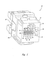
- FIG. 1 An embodiment of a Category 6 RJ series electrical connector jack 10 of the present invention is illustrated in Figure 1 fully assembled and ready for use.
- the jack 10 includes a dielectric housing or body 12 and a plurality of resilient contact tines 14 in parallel arrangement within an interior receptacle 16 of the body.
- the tines 14 may be spring wires with round or other cross-sectional shapes, elongated contact plates or have other suitable contact tine constructions. In the illustrated embodiment, eight tines 14 are used, but a fewer or greater number may be used as desired for the style connector while utilizing the principals of the invention.
- the body 12 is typically formed of plastic, and the tines 14 are formed of a conventional phosphor bronze metal used for Category 6 jacks and other style jacks.
- the tines 14 each have a first end portion 22 fixedly attached to a printed circuit board 24 and have a second free end portion 26.
- Each tine 14 has a first contact portion 28 extending between its first and second end portions 22 and 26.
- the first contact portions 28 are arranged in the body 12 to be contacted by the contacts 20 of the plug 18 when inserted into the receptacle 16.
- the first contact portions 28 of the tines 14 are in a generally parallel arrangement and the tines are essentially allowed to "float" as simple cantilevered beams.
- the printed circuit board 24 also supports eight insulation displacement contacts (IDCs) 30, each being electrically connected through the circuit paths on the printed circuit board to one of the eight tines 14.
- IDCs insulation displacement contacts
- Wires carrying electrical signals may be connected to the IDCs 30 in a conventional manner.
- Other style contacts and means may be used to electrically connect signals to the tines 14.
- the IDCs 30 are pressed into place in apertures in the printed circuit board 24, and the first end portions 22 of the tines 14 are first pressed into place in apertures in the printed circuit board and then soldered.
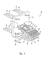
- a spring assembly 32 is mounted to the printed circuit board 24 in position below the tines as shown in Figure 3 .
- the spring assembly 32 has a pair of protrusions 34 which are inserted into apertures in the printed circuit board.
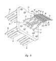
- the printed circuit board assembly indicated by reference numeral 33, is shown in Figure 3 ready for positioning within the body 12 of the connector jack 10, as is illustrated in Figure 4 .
- the receptacle 16 of the body 12 has a forward facing opening 35 in a forward end 36 of the body 12 which is sized to pass the plug 18 therethrough as it is inserted into the receptacle.
- a rearward end 38 of the body 12 has a chamber 40 with a rearward facing opening 42 sized to receive the assembled printed circuit board 24 therein.
- the printed circuit board 24 is positioned adjacent to the receptacle 16 with the tines 14 projecting forward into the receptacle in position for the first contact portions 28 thereof to be contacted by the contacts 20 of the plug 18 when inserted into the receptacle to make electrical contact therewith.
- a carrier or terminal b lock 43 shown i n Figure 1 , is mounted at and covers the rearward facing opening 42 of the chamber 40, and captures and holds the printed circuit board 24 in place. S naps securely connect the terminal block 43 to the body 12.
- the terminal block 43 has apertures to allow access to the IDCs 30 which project rearward from the printed circuit board 24 to allow connection of wires thereto.
- the tines 14 are laterally spaced apart so that one tine is contacted by a correspondingly positioned one of the plug contacts 20 when the plug 18 is inserted into the receptacle 16.
- the contact of the plug contacts 20 with the tines 14 moves the contacted tines in a generally downward direction, with a small rearward component, as the tines flex downward in response thereto.
- Each of the tines 14 is sufficiently resilient to produce a first generally upward force on the tine against the corresponding p lug contact 20 in response thereto. This serves as a contact force between the tine and the plug contact to help provide good electrical contact.
- the spring assembly 32 is positioned below the tines 14, as best seen in Figure 4 , to provide increased contact force and resiliency than the tines alone can produce in response to the tines moving downward as the plug 18 is inserted into the receptacle 16, without requiring the tines to be longer than desired to provide good electrical performance.
- the increased resiliency allows the insertion of legacy plugs into the receptacle 16 and the resulting extreme flexure of the tines 14 that can result, without permanent deformation of the tines.
- the spring assembly 32 includes eight resilient, non-conductive spring arms 44, each positioned immediately under a correspondingly positioned one of the tines 14.
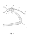
- a head portion 45 of each spring arm 44 is in contact with an underside of a second contact portion 47 of the tine opposite the side of the tine contacted by the plug contact 20.
- the second contact portion 47 is forward of the first end portion 22 of the tine 14 and rearward of the first contact portion 28, and located at a downward bend in the tine.
- the spring arms 44 extend forward from a spring assembly base 46, with a slight upward slant, and have a knee bend whereat the spring arms project generally upward and rearward and terminate in a free end portion including the head portion 45.
- Each of the spring arms 44 is positioned to have the head portion 45 thereof engaged by and move downward with the correspondingly positioned tine 14 as the tine moves downward when the plug 18 is inserted into the receptacle 16.
- the spring arm head portion 45 moves downward with a small rearward component since the tine deflects with an arcuate movement.
- each of the spring arms 44 is independently movable relative to the other ones of the spring arms, and each spring arm provides a second generally upward force on the correspondingly positioned tine which is transmitted to the plug contact 20 contacting the tine. This creates a supplemental upward force that causes an increased contact force between the tine and the plug contact (generally the sum of the first and second upward forces).
- the supplemental upward force also causes the tine to respond as if having greater resiliency than experienced by the unassisted tine, and assists the return movement of the tine when the plug 18 is removed from the receptacle 16 and allowed to return from its deflected position to its original position before the plug was inserted into the receptacle.
- This improvement in mechanical performance is accomplished without the need to lengthen and thicken the tines 14 to achieve it and thereby degrade electrical performance of the jack.
- each spring arm 44 operates on the tine 14 it engages independent of the other spring arms, the same characteristics of increased contact force and tine resiliency are experienced by a tine whether one tine or all eight tines are being engaged by plug contacts 20. This provides consistent performance characteristics for the jack 10.
- the body 12 align and hold the spring arms 44 in position for contact with the plug contacts 20.
- the body also includes features to capture the tines 14.
- the spring assembly 32 is manufactured of a non-conductive plastic, thus the spring arms 44 can directly contact the metal tines without requiring insulation or causing an electrical problem.
- the plastic is selected to provide a good life cycle with low creep or cold flow characteristics.
- the spring assembly 32 is composed of two separately molded components for ease of manufacture.
- the first component includes a first portion 46a of the base 46 which has the pair of protrusions 34 which secure the spring assembly 32 to the printed circuit board 24, and has every other one of the eight spring arms 44 projecting therefrom.
- the second component includes a second portion 46b of the base 46, and has the other four of the eight spring arms 44 projecting therefrom. Adjacent spring arms of the first component are separated by slightly greater than the width of one of the spring arms of the second component, and adjacent spring arms of the second component are separated by slightly greater than the width of one of the spring arms of the first component.
- the second contact portion 47 of each of the tines 14 has downwardly projecting left and right side skirts 47a and 47b, respectively, each having forward and rearward portions with a small notch therebetween at about the peak of a downward bend in the tine.
- the second contact portion 47 thus forms an inverted, longitudinally extending cupped trough of the tine 14.
- the head portion 45 of the spring arm 44 has a rounded contact portion in contact with the underside of the second contact portion 47 of the tine 14 in the trough area thereof between the left and right side skirts 47a and 47b which essentially trap or capture the head portion of the spring arm between the left and right side skirts against lateral movement relative to the tine engaged.
- the left and right side skirts 47a and 47b of the second contact portion 47 of the tine 14 extend in a forward-rearward direction and hence allow sliding movement of the h ead portion 45 of the spring arm 44 therebetween relative to the tine in the forward and rearward directions as the tine flexes and moves up and down during insertion and removal of the plug 18 or a legacy plug into or from the receptacle 16.
- the second contact portion 47 and head portion 45 form somewhat of a cup and ball socket with the head portion of the spring arm 44 captured in a recess or pocket defined by the deepest portion of the cupped trough of the second contact portion of the tine at about the peak of the bend in the tine.
- This arrangement provides a more positive engagement of the spring arm and the tine. While the present invention is illustrated and discussed with respect to a Category 6 jack, it should be understood that the invention is useful for many style jacks, including but not limited to Category 3, Category 5, Category 5e and other telecommunication and non-telecommunication jacks, and that the jacks need not utilize a printed circuit board mounting for the tines 14, spring assembly 32 or other components or utilize a printed circuit board at all.
Landscapes
- Coupling Device And Connection With Printed Circuit (AREA)
- Details Of Connecting Devices For Male And Female Coupling (AREA)
Claims (33)
- Steckerbuchse (10), die mit einem Stecker (18) mit einer Vielzahl von Steckerkontakten (20) verwendet werden kann, wobei die Buchse umfasst:einen Körper (12) mit einer Aufnahme (16), die zum Aufnehmen des Steckers (18) bemessen und aufgebaut ist; undeine Vielzahl von Kontaktzungen (14), die jeweils einen Kontaktabschnitt (28, 47) im Inneren der Aufnahme (16) aufweisen und so angeordnet sind, dass ein entsprechend angeordneter der Steckerkontakte (20) mit ihnen in Eingriff kommt, wenn der Stecker (18) in die Aufnahme (1) eingeführt wird;dadurch gekennzeichnet, dass die Steckerbuchse (10) des Weiteren umfasst:eine Vielzahl elastischer Federelemente (44), die jeweils so eingerichtet sind, dass sie auf eine der Kontaktzungen (14), wenn der entsprechend angeordnete Steckerkontakt (20) damit in Eingriff ist, eine Reaktionskraft in einer Richtung ausüben, in der eine zusätzliche Kontaktkraft zwischen der Kontaktzunge (14) und dem entsprechend angeordneten Steckerkontakt (20) erzeugt wird.
- Steckerbuchse nach Anspruch 1, wobei jede der Kontaktzungen (14) ein erstes Ende (22), das von einem Trageelement (24) getragen wird, sowie ein zweites, freies Ende (26) hat und sich der Kontaktabschnitt (28, 47) zwischen dem ersten und dem zweiten Ende (22, 26) an einer Position befindet, an der der entsprechend angeordnete der Steckerkontakte (20) damit in Eingriff kommt, wenn der Stecker (18) in die Aufnahme (16) eingeführt wird.
- Steckerbuchse nach Anspruch 1, wobei der Zungen-Kontaktabschnitt (28, 47) jeder Kontaktzunge (14) einen ersten Zungen-Kontaktabschnitt (28) sowie einen zweiten Zungen-Kontaktabschnitt (47) aufweist, jedes Federelement (44) einen Feder-Eingriffsabschnitt (45) aufweist, der erste Zungen-Kontaktabschnitt (28) so angeordnet ist, dass der entsprechende der Steckerkontakte (20) mit ihm in Kontakt kommt, wenn der Stecker (18) in die Aufnahme (16) eingeführt wird, der zweite Zungen-Kontaktabschnitt (47) so angeordnet ist, dass er mit dem Feder-Eingriffsabschnitt (45) in Eingriff ist, und der zweite Zungen-Kontaktabschnitt (47) ein Paar seitlicher Elemente (47a, 47b) enthält, die so weit beabstandet sind, dass der Feder-Eingriffsabschnitt (45) zwischen ihnen aufgenommen und gehalten wird, um seitliche Bewegung desselben einzuschränken, wenn der zweite Zungen-Kontaktabschnitt (47) in Eingriff mit dem Feder-Eingriffsabschnitt (45) ist.
- Steckerbuchse nach Anspruch 3, wobei der zweite Zungen-Kontaktabschnitt (47) länglich ist, sich die seitlichen Elemente (47a, 47b) in Längsrichtung an wenigstens einem Abschnitt des zweiten Zungen-Kontaktabschnitts (47) entlang erstrecken, ein seitlich begrenzter in Längsrichtung verlaufender Raum zwischen ihnen gebildet wird und der Raum zwischen den seitlichen Elementen (47a. 47b) im Wesentlichen frei ist, um Gleitbewegung des Feder-Eingriffsabschnitts (45) durch den Raum hindurch zu ermöglichen, wenn die Kontaktzunge (14) bewegt wird.
- Steckerbuchse nach Anspruch 3, wobei die Kontaktzunge (14) ein erstes Ende (22) sowie ein freies zweites Ende (26) hat, sich der erste Zungen-Kontaktabschnitt (28) zwischen dem ersten und dem zweiten Ende (22, 26) der Kontaktzunge (14) befindet und sich der zweite Zungen-Kontaktabschnitt (47) zwischen dem ersten Zungen-Kontaktabschnitt (28) und dem ersten Ende (22) der Kontaktzunge (14) befindet.
- Steckerbuchse nach Anspruch 3, wobei der Feder-Eingriffselementabschnitt (45) ein freier Endabschnitt der Federelementes (44) ist.
- Steckerbuchse nach Anspruch 1, wobei der Zungen-Kontaktabschnitt (28, 47) jeder Kontaktzunge (14) einen ersten Zungen-Kontaktabschnitt (28) sowie einen zweiten Zungen-Kontaktabschnitt (47) aufweist, jedes Federelement (44) einen Feder-Eingriffsabschnitt (45) aufweist, der erste Zungen-Kontaktabschnitt (28) so angeordnet ist, dass der entsprechende der Steckerkontakte (20) mit ihm in Kontakt kommt, wenn der Stecker (18) in die Aufnahme (16) eingeführt wird, der zweite Zungen-Kontaktabschnitt (47) so angeordnet ist, dass er mit dem Feder-Eingriffsabschnitt (45) in Eingriff ist, und der zweite Zungen-Kontaktabschnitt (47) eine Vertiefung aufweist, die so bemessen ist, dass sie den Feder-Eingriffsabschnitt (45) einschließt, um seitliche Bewegung des Feder-Eingriffsabschnitts (45) zu beschränken.
- Steckerbuchse nach Anspruch 7, wobei in dem zweiten Zungen-Kontaktabschnitt (47) in jeder Kontaktzunge (14) eine Biegung vorhanden ist, die wenigstens teilweise die Vertiefung bildet.
- Steckerbuchse nach Anspruch 8, wobei der zweite Zungen-Kontaktabschnitt (47) ein Paar seitlicher Elemente (47a, 47b) enthält, die so weit beabstandet sind, dass der Feder-Eingriffsabschnitt (45) zwischen ihnen aufgenommen und gehalten wird, um seitliche Bewegung desselben einzuschränken, wenn der zweite Zungen-Kontaktabschnitt (47) in Eingriff mit dem Feder-Eingriffsabschnitt (45) ist, und die seitlichen Elemente (47a, 47b) wenigstens teilweise die Vertiefung bilden.
- Steckerbuchse nach Anspruch 9, wobei der zweite Zungen-Kontaktabschnitt (47) länglich ist, sich die seitlichen Elemente (47a, 47b) in Längsrichtung an wenigstens einem Abschnitt des zweiten Zungen-Kontaktabschnitts (47) entlang erstrecken, ein seitlich begrenzter in Längsrichtung verlaufender Raum zwischen ihnen gebildet wird und der Raum zwischen den seitlichen Elementen (47a. 47b) im Wesentlichen frei ist, um Gleitbewegung des Feder-Eingriffsabschnitts (45) durch den Raum hindurch zu ermöglichen, wenn die Kontaktzunge (14) bewegt wird.
- Steckerbuchse nach Anspruch 7, wobei der Feder-Eingriffselementabschnitt (45) ein freier Endabschnitt der Federelementes (44) ist.
- Steckerbuchse nach Anspruch 7, wobei der Feder-Eingriffselementabschnitt (45) ein abgerundeter freier Endabschnitt der Federelementes (44) ist.
- Steckerbuchse nach Anspruch 1, die des Weiteren eine Leiterplatte (24) umfasst, die an die Aufnahme (16) angrenzend angeordnet ist;
wobei jede der Vielzahl von Kontaktzungen (14) ein erstes Ende (22), das fest an der Leiterplatte (24) angebracht ist, ein zweites, freies Ende (26) sowie einen Kontaktabschnitt (28, 47) zwischen dem ersten und dem zweiten Ende (22, 26) hat, sich die Zungen-Kontaktabschnitte (28, 47) im Inneren der Aufnahme (16) befinden und ein entsprechender der Steckerkontakte (20) mit ihnen in Kontakt kommt, sie in Reaktion darauf in einer ersten Richtung bewegt werden, wenn der Stecker (18) in die Aufnahme (16) eingeführt wird, und jede Zunge (14) ausreichend elastisch ist, um eine erste Kraft an dem Zungen-Kontaktabschnitt (28, 47) auf den entsprechenden Steckerkontakt in Reaktion darauf zu erzeugen, dass sie in der ersten Richtung bewegt worden ist;
und jedes der Vielzahl elastischer Federelemente ein nichtleitender länglicher Federarm (44) ist, jeder Federarm (44) einen unabhängig beweglichen Federelementabschnitt im Inneren der Aufnahme (16) hat, der an einen entsprechenden der Zungen-Kontaktabschnitte (28, 47) angrenzend so angeordnet ist, dass der entsprechenden Zungen-Kontaktabschnitt mit ihm in Eingriff kommt, wenn er durch den entsprechenden Steckerkontakt (20) in der ersten Richtung bewegt wird, wenn der Stecker (18) in die Aufnahme (16) eingeführt wird, und jeder Federarm (44) so eingerichtet ist, dass der Federelementabschnitt desselben eine zweite Kraft an dem entsprechenden Zungen-Kontaktabschnitt (28, 47) auf den entsprechenden Steckerkontakt (20) in Reaktion darauf ausübt, dass er in der ersten Richtung bewegt worden ist, um eine Kontaktkraft zwischen dem entsprechenden Zungen-Kontaktabschnitt (28, 47) und dem Steckerkontakt (20) zu erzeugen, die im Wesentlichen der Summe aus der ersten und der zweiten Kraft gleich ist, und Rückkehrbewegung des entsprechenden Zungen-Kontaktabschnitts (28, 47) in einer zweiten Richtung entgegengesetzt zu der ersten Richtung zu unterstützen, wenn der Stecker (18) aus der Aufnahme (16) entfernt wird. - Steckerbuchse nach Anspruch 13, wobei der Zungen-Kontaktabschnitt (28, 47) jeder Kontaktzunge (14) einen ersten Zungen-Kontaktabschnitt (28) sowie einen zweiten Zungen-Kontaktabschnitt (47) aufweist, der Federelementabschnitt jedes Federarms (44) einen Feder-Eingriffsabschnitt (45) aufweist, der erste Zungen-Kontaktabschnitt (28) so angeordnet ist, dass der entsprechende der Steckerkontakte (20) mit ihm in Kontakt kommt, wenn der Stecker (18) in die Aufnahme (16) eingeführt wird, der zweite Zungen-Kontaktabschnitt (47) so angeordnet ist, dass er mit dem Feder-Eingriffsabschnitt (45) in Eingriff ist, und der zweite Zungen Kontaktabschnitt (47) ein Paar seitlicher Elemente (47a, 47b) enthält, die so weit beabstandet sind, dass der Feder-Eingriffsabschnitt (45) zwischen ihnen aufgenommen und gehalten wird, um seitliche Bewegung desselben einzuschränken, wenn der zweite Zungen-Kontaktabschnitt (47) in Eingriff mit dem Feder-Eingriffsabschnitt (45) ist.
- Steckerbuchse nach Anspruch 14, wobei der zweite Zungen-Kontaktabschnitt (47) länglich ist, sich die seitlichen Elemente (47a, 47b) in Längsrichtung an wenigstens einem Abschnitt des zweiten Zungen-Kontaktabschnitts (47) entlang erstrecken, ein seitlich begrenzter in Längsrichtung verlaufender Raum zwischen ihnen gebildet wird und der Raum zwischen den seitlichen Elementen (47a. 47b) im Wesentlichen frei ist, um Gleitbewegung des Feder-Eingriffsabschnitts (45) durch den Raum hindurch zu ermöglichen, wenn die Kontaktzunge (14) bewegt wird.
- Steckerbuchse nach Anspruch 14, wobei sich der erste Zungen-Kontaktabschnitt (28) zwischen dem ersten und dem zweiten Ende (22, 26) der Zunge (14) befindet und sich der zweite Zungen-Kontaktabschnitt (47) zwischen dem ersten Zungen-Kontaktabschnitt (28) und dem ersten Ende (22) der Zunge (14) befindet.
- Steckerbuchse nach Anspruch 14, wobei der Feder-Eingriffselementabschnitt (45) ein freier Endabschnitt der Federelementes (44) ist.
- Steckerbuchse nach Anspruch 13, wobei der Zungen-Kontaktabschnitt (28, 47) jeder Zunge (14) einen ersten Zungen-Kontaktabschnitt (28) sowie einen zweiten Zungen-Kontaktabschnitt (47) aufweist, jedes Federelement (44) einen Feder-Eingriffsabschnitt (45) aufweist, der erste Zungen-Kontaktabschnitt (28) so angeordnet ist, dass der entsprechende der Steckerkontakte (20) mit ihm in Kontakt kommt, wenn der Stecker (18) in die Aufnahme (16) eingeführt wird, der zweite Zungen-Kontaktabschnitt (47) so angeordnet ist, dass er mit dem Feder-Eingriffsabschnitt (45) in Eingriff ist, und der zweite Zungen-Kontaktabschnitt (47) eine Vertiefung aufweist, die so bemessen ist, dass sie den Feder-Eingriffsabschnitt (45) einschließt, um seitliche Bewegung des Feder-Eingriffsabschnitts (45) zu beschränken.
- Steckerbuchse nach Anspruch 18, wobei in dem zweiten Zungen-Kontaktabschnitt (47) in jeder Kontaktzunge (14) eine Biegung vorhanden ist, die wenigstens teilweise die Vertiefung bildet.
- Steckerbuchse nach Anspruch 19, wobei der zweite Zungen-Kontaktabschnitt (47) ein Paar seitlicher Elemente (47a, 47b) enthält, die so weit beabstandet sind, dass der Feder-Eingriffsabschnitt (45) zwischen ihnen aufgenommen und gehalten wird, um seitliche Bewegung desselben einzuschränken, wenn der zweite Zungen-Kontaktabschnitt (47) in Eingriff mit dem Feder-Eingriffsabschnitt (45) ist, und die seitlichen Elemente (47a, 47b) wenigstens teilweise die Vertiefung bilden.
- Steckerbuchse nach Anspruch 20, wobei der zweite Zungen-Kontaktabschnitt (47) länglich ist, sich die seitlichen Elemente (47a, 47b) in Längsrichtung an wenigstens einem Abschnitt des zweiten Zungen-Kontaktabschnitts (47) entlang erstrecken, ein seitlich begrenzter in Längsrichtung verlaufender Raum zwischen ihnen gebildet wird und der Raum zwischen den seitlichen Elementen (47a. 47b) im Wesentlichen frei ist, um Gleitbewegung des Feder-Eingriffsabschnitts (45) durch den Raum hindurch zu ermöglichen, wenn die Kontaktzunge (14) bewegt wird.
- Steckerbuchse nach Anspruch 18, wobei der Feder-Eingriffselementabschnitt (45) ein freier Endabschnitt der Federelementes (44) ist.
- Steckerbuchse nach Anspruch 18, wobei der Feder-Eingriffselementabschnitt (45) ein abgerundeter freier Endabschnitt der Federelementes (44) ist.
- Steckerbuchse (10) nach Anspruch 1, die des Weiteren eine Leiterplatte (24) umfasst;
wobei sich die Vielzahl von Kontaktzungen (14) im Inneren der Aufnahme (16) erstrecken, jede ein erstes Ende (22), das fest an der Leiterplatte (24) angebracht ist, sowie ein zweites freies Ende (26) hat, sich die Kontaktzungen (14) im Inneren der Aufnahme (16) befinden, ein entsprechender der Steckerkontakte (20) mit ihnen in Kontakt kommt, sie in Reaktion darauf in einer ersten Richtung bewegt werden, wenn der Stecker (18) in die Aufnahme (16) eingeführt wird, und jede Kontaktzunge (14) ausreichend elastisch ist, um eine erste Kontaktkraft zwischen der entsprechenden Kontaktzunge (14) und dem Steckerkontakt (20) in Reaktion darauf zu erzeugen, dass der entsprechende Steckerkontakt (20) mit ihr in Kontakt gekommen ist und sie von ihm in der ersten Richtung bewegt worden ist;
und jedes der Vielzahl elastischer Federelemente (44) länglich ist, sich im Inneren der Aufnahme (16) erstreckt, jeweils an eine entsprechende der Kontaktzungen (14) angrenzend angeordnet ist, die entsprechende Kontaktzunge damit in Eingriff kommt, wenn sie durch den entsprechenden Steckerkontakt (20) in der ersten Richtung bewegt wird, wenn der Stecker (18) in die Aufnahme (16) eingeführt wird, und jedes Federelement (44) so eingerichtet ist, dass es in Reaktion darauf, dass der entsprechende Steckerkontakt (20) mit der entsprechenden Kontaktzunge in Kontakt gekommen ist und sie durch ihn in der ersten Richtung bewegt worden ist, eine Kraft auf die entsprechende Kontaktzunge (14) ausübt, um zusätzlich zu der ersten Kontaktkraft eine zweite Kontaktkraft zwischen der entsprechenden Kontaktzunge (14) und dem Steckerkontakt (20) zu erzeugen. - Steckerbuchse (10) nach Anspruch 1, die des Weiteren eine Leiterplatte (24) umfasst;
wobei jede der Vielzahl von Kontaktzungen (14) ein erstes Ende (22), das fest an der Leiterplatte (24) angebracht ist, ein zweites, freies Ende (26) sowie einen Kontaktabschnitt (28, 47) zwischen dem ersten und dem zweiten Ende (22, 26) hat, die Kontaktabschnitte (28, 47) jeweils eine erste Seite sowie eine gegenüberliegende zweite Seite haben, sich die Kontaktzungen (14) im Inneren der Aufnahme (16) erstrecken und so angeordnet sind, dass entsprechend angeordnete der Steckerkontakte (20) mit den ersten Seiten der Kontaktabschnitte (28) in Eingriff kommen und die in Eingriff befindlichen Kontaktzungen (14) in einer ersten im Allgemeinen seitlichen Richtung bewegen, wenn der Stecker (18) in die Aufnahme (16) eingeführt wird, und jede Kontaktzunge (14) ausreichend elastisch ist, um in Reaktion darauf, dass sie durch den Steckerkontakt (20) bewegt wird, eine erste Kraft in einer zweiten Richtung entgegengesetzt zu der ersten Richtung auf den entsprechend angeordneten Steckerkontakt (20) auszuüben; und
jedes der Vielzahl elastischer Federelemente (44), die sich im Inneren der Aufnahme (16) erstrecken, jeweils an die zweite Seite des Kontaktabschnitts (28, 47) einer entsprechend angeordneten der Kontaktzungen (14) an einer Position angrenzt, an der es damit in Eingriff kommt, wenn die entsprechend angeordnete Kontaktzunge (14) durch den entsprechend angeordneten Steckerkontakt (20) in der ersten Richtung bewegt wird, wenn der Stecker (18) in die Aufnahme (16) eingeführt wird, und die Federelemente (44) jeweils so eingerichtet sind, dass sie eine zweite Kraft auf die entsprechend angeordnete Kontaktzunge (14) in der zweiten Richtung ausüben, um eine Kontaktkraft zwischen der in Eingriff befindlichen entsprechend angeordneten Kontaktzunge und dem Steckerkontakt (20) zu erzeugen, die im Wesentlichen der Summe aus der ersten und der zweiten Kraft gleich ist, und Rückkehrbewegung der in Eingriff befindlichen entsprechend angeordneten Kontaktzunge (14) in der zweiten Richtung zu unterstützen, wenn der Stecker (18) aus der Aufnahme (16) entnommen wird. - Steckerbuchse nach Anspruch 1, wobei
jede der Vielzahl von Kontaktzungen (14) so angeordnet ist, dass sich wenigstens ein Abschnitt derselben im Inneren der Aufnahme (16) befindet, ein entsprechender der Steckerkontakte (20) damit in Kontakt gebracht wird, sie in Reaktion darauf in einer ersten Richtung bewegt wird, wenn der Stecker (18) in die Aufnahme (16) eingeführt wird, und jede Kontaktzunge (14) ausreichend elastisch ist, um eine erste Kontaktkraft zwischen der entsprechenden Kontaktzunge (14) und dem Steckerkontakt (20) in Reaktion darauf zu erzeugen, dass der entsprechende Steckerkontakt (20) mit ihr in Kontakt gekommen ist und sie durch ihn bewegt worden ist; und
jedes der Vielzahl elastischer Federelemente (44) so angeordnet ist, dass sich wenigstens ein Abschnitt desselben an eine entsprechende der Kontaktzungen (14) angrenzend im Inneren der Aufnahme (16) befindet, die entsprechende Kontaktzunge mit ihm in Eingriff kommt, wenn sie durch den entsprechenden Steckerkontakt (20) in der ersten Richtung bewegt wird, wenn der Stecker (18) in die Aufnahme (16) eingeführt wird, und jedes Federelement (44) so eingerichtet ist, dass es in Reaktion darauf, dass der entsprechende Steckerkontakt (20) mit der entsprechenden Kontaktzunge (14) in Kontakt gekommen ist und sie durch ihn in der ersten Richtung bewegt worden ist, eine Kraft auf die entsprechende Kontaktzunge (14) ausübt, um zusätzlich zu der ersten Kontaktkraft eine zweite Kontaktkraft zwischen der entsprechenden Zunge und dem Kontakt des Steckers (18) zu erzeugen. - Steckerbuchse nach Anspruch 26, wobei jede der Kontaktzungen (14) ein erstes Ende (22), das von einem Trageelement (24) getragen wird, ein zweites, freies Ende (26) sowie einen Kontaktabschnitt (28, 47) zwischen dem ersten und dem zweiten Ende hat, der so angeordnet ist, dass ein entsprechender der Steckerkontakte (20) damit in Kontakt gebracht wird.
- Steckerbuchse nach Anspruch 1, wobei
sich jede der Vielzahl von Kontaktzungen (14) im Inneren der Aufnahme (16) erstreckt, sie sich jeweils an einer Position befindet, an der ein entsprechender der Steckerkontakte (20) mit ihr in Kontakt kommt und sie sich in Reaktion darauf von einer ersten Position an eine zweite Position bewegt, wenn sich der Stecker (18) in die Aufnahme (16) befindet; und sich jedes der Vielzahl elastischer Federelemente (44) im Inneren der Aufnahme (16) erstreckt, an eine entsprechende der Kontaktzungen (14) angrenzend angeordnet ist, so dass die entsprechende Kontaktzunge damit in Eingriff kommt, wenn sie durch den entsprechenden Steckerkontakt (20) von der ersten Position an die zweite Position bewegt wird, wenn sich der Stecker (18) in der Aufnahme (16) befindet, und jedes Federelement (44) so eingerichtet ist, dass es eine Kraft auf die entsprechende Kontaktzunge (14) in einer Richtung von der zweiten Position auf die erste Position zu ausübt, um eine Kontaktkraft zwischen der entsprechenden Kontaktzunge und dem Steckerkontakt (20) auszuüben, wenn sich der Stecker (18) in der Aufnahme (16) befindet. - Steckerbuchse nach Anspruch 28, wobei jede der Kontaktzungen (14) ein erstes Ende (22), das von einem Trageelement (24) getragen wird, ein zweites, freies Ende (26) sowie einen Kontaktabschnitt (28, 47) zwischen dem ersten und dem zweiten Ende (22, 26) hat, der so angeordnet ist, dass ein entsprechender der Steckerkontakte (20) damit in Kontakt kommt.
- Steckerbuchse nach Anspruch 28, wobei jedes Federelement (44) so eingerichtet ist, dass es, wenn sich die entsprechende Kontaktzunge (14) an der zweiten Position befindet, die Kraft in ausreichendem Maß auf die entsprechende Kontaktzunge (14) ausübt, um wenigstens unterstützend beim Bewegen der entsprechenden Kontaktzunge (14) an die erste Position zu wirken, wenn der Stecker (18) aus der Aufnahme (16) entfernt wird.
- Steckerbuchse nach Anspruch 1, wobei
jede der Vielzahl von Kontaktzungen (14) eine erste Seite sowie eine gegenüberliegende zweite Seite hat, die erste Seite jeder Kontaktzunge (14) einen Kontaktabschnitt (28) im Inneren der Aufnahme (16) hat, der so angeordnet ist, dass ein entsprechend angeordneter der Steckerkontakte (20) mit ihm in Eingriff kommt, wenn der Stecker (18) in die Aufnahme (16) eingeführt wird; und
jedes der Vielzahl elastischer Federelemente (44) an die zweite Seite einer entsprechend angeordneten der Kontaktzungen (14) angrenzend angeordnet ist, so dass die Federelemente (44), die den Kontaktzungen (14) entsprechen, mit denen die entsprechend angeordneten Steckerkontakte (20) in Eingriff sind, jeweils eine Reaktionskraft auf die entsprechende in Eingriff befindliche Kontaktzunge (14) ausüben, um eine Kontaktkraft zwischen der entsprechenden in Eingriff befindlichen Kontaktzunge (14) und dem entsprechend angeordneten Steckerkontakt (20) zu erzeugen. - Steckerbuchse nach Anspruch 31, wobei jede der Kontaktzungen (14) ein erstes Ende (22), das von einem Trageelement (24) getragen wird, sowie ein zweites, freies Ende (26) hat und sich der Kontaktabschnitt (28, 47) zwischen dem ersten und dem zweiten Ende (22, 26) an einer Position befindet, an der der entsprechend angeordnete der Steckerkontakte (20) damit in Eingriff kommt, wenn der Stecker (18) in die Aufnahme (16) eingeführt wird.
- Steckerbuchse nach Anspruch 31, wobei jeweils wenigstens ein Abschnitt (45) der Federelemente (44) jeweils im Inneren der Aufnahme (16) und an die zweite Seite der entsprechend angeordneten der Kontaktzungen (14) angrenzend angeordnet ist, so dass die Federelementabschnitte (45), die den Kontaktzungen (14) entsprechen, mit denen die entsprechend angeordneten Steckerkontakte (20) in Eingriff sind, jeweils die Reaktionskraft auf die entsprechende in Eingriff befindliche Kontaktzunge (14) ausüben, um die Kontaktkraft zwischen der entsprechenden in Eingriff befindlichen Kontaktzunge (14) und dem entsprechend angeordneten Steckerkontakt (20) zu erzeugen.
Priority Applications (1)
| Application Number | Priority Date | Filing Date | Title |
|---|---|---|---|
| EP12006958.8A EP2562884B1 (de) | 2002-09-27 | 2003-09-16 | Elektrische Steckerbuchse |
Applications Claiming Priority (5)
| Application Number | Priority Date | Filing Date | Title |
|---|---|---|---|
| US261165 | 2002-09-27 | ||
| US10/261,165 US6641443B1 (en) | 2002-09-27 | 2002-09-27 | Electrical connector jack |
| US662042 | 2003-09-12 | ||
| US10/662,042 US6786776B2 (en) | 2002-09-27 | 2003-09-12 | Electrical connector jack |
| PCT/US2003/029150 WO2004030155A1 (en) | 2002-09-27 | 2003-09-16 | Electrical connector jack |
Related Child Applications (2)
| Application Number | Title | Priority Date | Filing Date |
|---|---|---|---|
| EP12006958.8A Division EP2562884B1 (de) | 2002-09-27 | 2003-09-16 | Elektrische Steckerbuchse |
| EP12006958.8 Division-Into | 2012-10-08 |
Publications (2)
| Publication Number | Publication Date |
|---|---|
| EP1543590A1 EP1543590A1 (de) | 2005-06-22 |
| EP1543590B1 true EP1543590B1 (de) | 2013-08-14 |
Family
ID=34278093
Family Applications (2)
| Application Number | Title | Priority Date | Filing Date |
|---|---|---|---|
| EP12006958.8A Expired - Lifetime EP2562884B1 (de) | 2002-09-27 | 2003-09-16 | Elektrische Steckerbuchse |
| EP03754650.4A Expired - Lifetime EP1543590B1 (de) | 2002-09-27 | 2003-09-16 | Elektrischer jack verbinder |
Family Applications Before (1)
| Application Number | Title | Priority Date | Filing Date |
|---|---|---|---|
| EP12006958.8A Expired - Lifetime EP2562884B1 (de) | 2002-09-27 | 2003-09-16 | Elektrische Steckerbuchse |
Country Status (10)
| Country | Link |
|---|---|
| US (1) | US6786776B2 (de) |
| EP (2) | EP2562884B1 (de) |
| KR (1) | KR101020120B1 (de) |
| CN (1) | CN100338820C (de) |
| AU (1) | AU2003272469B2 (de) |
| BR (1) | BR0314792A (de) |
| CA (1) | CA2497963C (de) |
| MX (1) | MXPA05003250A (de) |
| TW (1) | TWI285985B (de) |
| WO (1) | WO2004030155A1 (de) |
Families Citing this family (58)
| Publication number | Priority date | Publication date | Assignee | Title |
|---|---|---|---|---|
| US7052328B2 (en) | 2002-11-27 | 2006-05-30 | Panduit Corp. | Electronic connector and method of performing electronic connection |
| CA2464834A1 (en) | 2004-04-19 | 2005-10-19 | Nordx/Cdt Inc. | Connector |
| US20060252308A1 (en) * | 2005-05-05 | 2006-11-09 | Siemens Westinghouse Power Corp. | Hazard boundary termination box |
| US7134915B1 (en) * | 2005-12-16 | 2006-11-14 | Superworld Electronics Co., Ltd. | Base structure for communication module |
| US20070141892A1 (en) * | 2005-12-21 | 2007-06-21 | Tyco Electronics Corporation | Cable manager for modular jacks |
| DE102006010279A1 (de) * | 2006-03-02 | 2007-09-06 | Mc Technology Gmbh | Stecker für geschirmte Datenkabel |
| US7591686B2 (en) * | 2006-04-18 | 2009-09-22 | Commscope, Inc. Of North Carolina | Communications connectors with jackwire contacts and printed circuit boards |
| US7740282B2 (en) * | 2006-05-05 | 2010-06-22 | Leviton Manufacturing Co., Inc. | Port identification system and method |
| TWM301448U (en) * | 2006-06-02 | 2006-11-21 | Jyh Eng Technology Co Ltd | Network connector |
| DE102007005959A1 (de) | 2007-02-06 | 2008-08-14 | Adc Gmbh | Steckverbinder |
| EP2137794B1 (de) * | 2007-03-29 | 2018-03-07 | The Siemon Company | Modularer verbinder mit verringerter abschlussvariabilität und verbesserter leistungsfähigkeit |
| US7427218B1 (en) * | 2007-05-23 | 2008-09-23 | Commscope, Inc. Of North Carolina | Communications connectors with staggered contacts that connect to a printed circuit board via contact pads |
| KR20100074141A (ko) * | 2007-09-19 | 2010-07-01 | 레비톤 메뉴팩튜어링 캄파니 인코포레이티드 | 통신 콘센트 내에 위치된 플렉서블 인쇄회로보드 상에 형성되는 내부 누화 보상 회로와 이에 관련된 방법 및 시스템 |
| US7967645B2 (en) * | 2007-09-19 | 2011-06-28 | Leviton Manufacturing Co., Inc. | High speed data communications connector circuits, systems, and methods for reducing crosstalk in communications systems |
| US7736195B1 (en) | 2009-03-10 | 2010-06-15 | Leviton Manufacturing Co., Inc. | Circuits, systems and methods for implementing high speed data communications connectors that provide for reduced modal alien crosstalk in communications systems |
| US20090186532A1 (en) * | 2008-01-18 | 2009-07-23 | Commscope, Inc. | Communications jacks with selectively engageable contact support structures |
| US7547227B1 (en) | 2008-04-21 | 2009-06-16 | Leviton Manufacturing Co., Inc. | Adhesive laminate label for a communication connector jack and communication connector jack including same |
| US7601034B1 (en) * | 2008-05-07 | 2009-10-13 | Ortronics, Inc. | Modular insert and jack including moveable reactance section |
| US7976348B2 (en) * | 2008-05-07 | 2011-07-12 | Ortronics, Inc. | Modular insert and jack including moveable reactance section |
| TW201010211A (en) | 2008-08-19 | 2010-03-01 | John Peng | Network jack and method for processing the same |
| US7670194B1 (en) | 2008-10-27 | 2010-03-02 | Commscope, Inc. Of North Carolina | RJ-45 style communications jacks having mechanisms that prevent an RJ-11 style communications plug from being fully inserted within the jack |
| US7914346B2 (en) * | 2008-11-04 | 2011-03-29 | Commscope, Inc. Of North Carolina | Communications jacks having contact wire configurations that provide crosstalk compensation |
| US7682203B1 (en) * | 2008-11-04 | 2010-03-23 | Commscope, Inc. Of North Carolina | Communications jacks having contact wire configurations that provide crosstalk compensation |
| US7794286B2 (en) * | 2008-12-12 | 2010-09-14 | Hubbell Incorporated | Electrical connector with separate contact mounting and compensation boards |
| US7985101B2 (en) | 2009-01-26 | 2011-07-26 | Commscope, Inc. Of North Carolina | RJ-45 style communications jacks that are configured to receive both RJ-45 and RJ-11 style communications plugs |
| US7967644B2 (en) | 2009-08-25 | 2011-06-28 | Tyco Electronics Corporation | Electrical connector with separable contacts |
| US8016621B2 (en) | 2009-08-25 | 2011-09-13 | Tyco Electronics Corporation | Electrical connector having an electrically parallel compensation region |
| US8435082B2 (en) | 2010-08-03 | 2013-05-07 | Tyco Electronics Corporation | Electrical connectors and printed circuits having broadside-coupling regions |
| US7850492B1 (en) | 2009-11-03 | 2010-12-14 | Panduit Corp. | Communication connector with improved crosstalk compensation |
| US7857667B1 (en) * | 2009-11-19 | 2010-12-28 | Leviton Manufacturing Co., Inc. | Spring assembly with spring members biasing and capacitively coupling jack contacts |
| GB201000863D0 (en) * | 2010-01-20 | 2010-03-10 | Wheeler & Clinch Ltd | A connector assembly |
| EP2403069B1 (de) * | 2010-07-02 | 2017-05-17 | Nexans | Kommunikationsanordnung mit einem Steckverbinder und einer Buchsenanordnung zur gemeinsamen Verbindung |
| US8202129B2 (en) | 2010-10-19 | 2012-06-19 | Jyh Eng Technology Co., Ltd. | Network connector with an elastic terminal support rack |
| EP2630698B1 (de) | 2010-10-22 | 2017-02-22 | ADC Telecommunications, Inc. | Kontaktsatzanordnung für rechtwinkelige buchse |
| US8388386B2 (en) * | 2010-10-22 | 2013-03-05 | Adc Telecommunications, Inc. | Plug contact arrangement and the manufacture thereof |
| US8715002B2 (en) | 2011-01-27 | 2014-05-06 | Commscope, Inc. Of North Carolina | Modular communications jack with user-selectable mounting |
| US8425255B2 (en) | 2011-02-04 | 2013-04-23 | Leviton Manufacturing Co., Inc. | Spring assembly with spring members biasing and capacitively coupling jack contacts |
| US8641452B2 (en) * | 2011-03-22 | 2014-02-04 | Panduit Corp. | Communication jack having an insulating element connecting a spring element and a spring end of a contact element |
| US8715012B2 (en) | 2011-04-15 | 2014-05-06 | Adc Telecommunications, Inc. | Managed electrical connectivity systems |
| WO2012177486A2 (en) | 2011-06-21 | 2012-12-27 | Adc Telecommunications, Inc. | Connector with cable retention feature and patch cord having the same |
| US8684763B2 (en) | 2011-06-21 | 2014-04-01 | Adc Telecommunications, Inc. | Connector with slideable retention feature and patch cord having the same |
| US9800350B2 (en) * | 2012-01-23 | 2017-10-24 | Intel Corporation | Increased density SFP connector |
| US8790139B2 (en) * | 2012-06-22 | 2014-07-29 | Commscope, Inc. Of North Carolina | Communications jacks having sliding contacts and/or contacts having insulative base members |
| WO2014008132A1 (en) | 2012-07-06 | 2014-01-09 | Adc Telecommunications, Inc. | Managed electrical connectivity systems |
| US9203198B2 (en) | 2012-09-28 | 2015-12-01 | Commscope Technologies Llc | Low profile faceplate having managed connectivity |
| US9281622B2 (en) | 2012-12-07 | 2016-03-08 | Commscope, Inc. Of North Carolina | Communications jacks having low-coupling contacts |
| US9083096B2 (en) * | 2013-02-22 | 2015-07-14 | Tyco Electronics Corporation | Telecommunication jack with contacts of multiple materials |
| US9343822B2 (en) | 2013-03-15 | 2016-05-17 | Leviton Manufacturing Co., Inc. | Communications connector system |
| US9627827B2 (en) | 2014-04-14 | 2017-04-18 | Leviton Manufacturing Co., Inc. | Communication outlet with shutter mechanism and wire manager |
| EP4329110A3 (de) | 2014-04-14 | 2024-07-24 | Leviton Manufacturing Company, Inc. | Kommunikationsausgang mit blendenmechanismus und drahtmanager |
| US9515437B2 (en) | 2014-04-14 | 2016-12-06 | Leviton Manufacturing Co., Inc. | Communication outlet with shutter mechanism and wire manager |
| USD752590S1 (en) | 2014-06-19 | 2016-03-29 | Leviton Manufacturing Co., Ltd. | Communication outlet |
| US10151890B2 (en) | 2015-03-18 | 2018-12-11 | Leviton Manufacturing Co., Inc. | Data communication port insert configurable with indicia to customize data communication station labeling and identification |
| US9608379B1 (en) | 2015-10-14 | 2017-03-28 | Leviton Manufacturing Co., Inc. | Communication connector |
| US10637196B2 (en) | 2015-11-11 | 2020-04-28 | Bel Fuse (Macao Commercial Offshore) Limited | Modular jack contact assembly having controlled capacitive coupling positioned within a jack housing |
| JP6655183B2 (ja) | 2015-11-11 | 2020-02-26 | ベル フューズ (マカオ コマーシャル オフショア) リミテッド | モジュラーコネクタ |
| US10135207B2 (en) | 2016-01-31 | 2018-11-20 | Leviton Manufacturing Co., Inc. | High-speed data communications connector |
| US9843121B1 (en) * | 2016-08-23 | 2017-12-12 | Leviton Manufacturing Co., Inc. | Communication connector having contact pads contacted by movable contact members |
Family Cites Families (17)
| Publication number | Priority date | Publication date | Assignee | Title |
|---|---|---|---|---|
| JPS59138185U (ja) * | 1983-03-04 | 1984-09-14 | ホシデン株式会社 | ジヤツク |
| US5299956B1 (en) | 1992-03-23 | 1995-10-24 | Superior Modular Prod Inc | Low cross talk electrical connector system |
| DE9207521U1 (de) * | 1992-06-05 | 1993-08-19 | Filtec Filtertechnologie für die Elektronikindustrie GmbH, 59557 Lippstadt | Mehrpoliger Steckverbinder für elektronische Signalleitungen |
| TW218060B (en) | 1992-12-23 | 1993-12-21 | Panduit Corp | Communication connector with capacitor label |
| US5470244A (en) | 1993-10-05 | 1995-11-28 | Thomas & Betts Corporation | Electrical connector having reduced cross-talk |
| US5425658A (en) | 1993-10-29 | 1995-06-20 | Bundy Corporation | Card edge connector with reduced contact pitch |
| US5431584A (en) | 1994-01-21 | 1995-07-11 | The Whitaker Corporation | Electrical connector with reduced crosstalk |
| US5586914A (en) | 1995-05-19 | 1996-12-24 | The Whitaker Corporation | Electrical connector and an associated method for compensating for crosstalk between a plurality of conductors |
| US6062918A (en) * | 1996-07-01 | 2000-05-16 | The Whitaker Corporation | Electrical receptacle contact assembly |
| CN2281006Y (zh) * | 1996-10-15 | 1998-05-06 | 黄阿招 | 连接器端子 |
| GB2322976A (en) * | 1997-02-28 | 1998-09-09 | Molex Inc | Data communications connectors |
| US6409547B1 (en) | 1998-12-02 | 2002-06-25 | Nordx/Cdt, Inc. | Modular connectors with compensation structures |
| JP4428765B2 (ja) * | 1999-08-30 | 2010-03-10 | パナソニック電工株式会社 | モジュラジャック |
| CN1090393C (zh) * | 1999-10-29 | 2002-09-04 | 富士康(昆山)电脑接插件有限公司 | 插座连接器 |
| US6554653B2 (en) * | 2001-03-16 | 2003-04-29 | Adc Telecommunications, Inc. | Telecommunications connector with spring assembly and method for assembling |
| US6450837B1 (en) * | 2001-10-29 | 2002-09-17 | Hon Hai Precision Ind. Co., Ltd. | Electrical connector having surge suppressing device |
| US6641443B1 (en) * | 2002-09-27 | 2003-11-04 | Leviton Manufacturing Co., Inc. | Electrical connector jack |
-
2003
- 2003-09-12 US US10/662,042 patent/US6786776B2/en not_active Expired - Lifetime
- 2003-09-16 EP EP12006958.8A patent/EP2562884B1/de not_active Expired - Lifetime
- 2003-09-16 KR KR1020057005156A patent/KR101020120B1/ko not_active Expired - Fee Related
- 2003-09-16 CN CNB038230623A patent/CN100338820C/zh not_active Expired - Fee Related
- 2003-09-16 BR BR0314792-4A patent/BR0314792A/pt not_active Application Discontinuation
- 2003-09-16 CA CA002497963A patent/CA2497963C/en not_active Expired - Fee Related
- 2003-09-16 EP EP03754650.4A patent/EP1543590B1/de not_active Expired - Lifetime
- 2003-09-16 AU AU2003272469A patent/AU2003272469B2/en not_active Ceased
- 2003-09-16 MX MXPA05003250A patent/MXPA05003250A/es active IP Right Grant
- 2003-09-16 WO PCT/US2003/029150 patent/WO2004030155A1/en not_active Ceased
- 2003-09-26 TW TW092126642A patent/TWI285985B/zh not_active IP Right Cessation
Also Published As
| Publication number | Publication date |
|---|---|
| US6786776B2 (en) | 2004-09-07 |
| CN1685571A (zh) | 2005-10-19 |
| CA2497963C (en) | 2009-11-17 |
| EP2562884B1 (de) | 2018-05-02 |
| AU2003272469B8 (en) | 2004-04-19 |
| KR101020120B1 (ko) | 2011-03-08 |
| CA2497963A1 (en) | 2004-04-08 |
| KR20050067157A (ko) | 2005-06-30 |
| BR0314792A (pt) | 2005-07-26 |
| WO2004030155A1 (en) | 2004-04-08 |
| EP2562884A1 (de) | 2013-02-27 |
| CN100338820C (zh) | 2007-09-19 |
| US20040127105A1 (en) | 2004-07-01 |
| MXPA05003250A (es) | 2005-07-05 |
| AU2003272469A1 (en) | 2004-04-19 |
| TW200421674A (en) | 2004-10-16 |
| TWI285985B (en) | 2007-08-21 |
| AU2003272469B2 (en) | 2007-05-24 |
| EP1543590A1 (de) | 2005-06-22 |
Similar Documents
| Publication | Publication Date | Title |
|---|---|---|
| EP1543590B1 (de) | Elektrischer jack verbinder | |
| US6641443B1 (en) | Electrical connector jack | |
| EP1304770B1 (de) | Koaxialverbinder mit einem Schalter | |
| US4428636A (en) | Multi-contact connectors for closely spaced conductors | |
| EP0795929B1 (de) | Elektrische Verbinderanordnung mit verbessertem Haltemittel | |
| EP0608851B1 (de) | Elektrische Kontaktstruktur mit geringer Einsteckkraft | |
| US7794253B2 (en) | Coaxial connector with a new type of contact | |
| US20050227524A1 (en) | Modular jack with a detective switch | |
| CA1146231A (en) | Electrical plug receptacle connector | |
| US5993263A (en) | Reduced mating force electrical connector | |
| EP1128477B1 (de) | Elektrischer Verbinder mit Kompressionskontakten | |
| WO2011063142A2 (en) | A spring assembly with spring members biasing and capacitively coupling jack contacts | |
| WO1985005006A1 (en) | Dual in-line package carrier assembly | |
| US5997329A (en) | Enhanced connector system | |
| CA1075788A (en) | Printed circuit board edge connector | |
| US7063571B2 (en) | Smart card connector | |
| US6231362B1 (en) | Electrical connector with an improved switch structure | |
| US20050176289A1 (en) | Battery connector | |
| US20240396269A1 (en) | Electrical connector | |
| US20020142667A1 (en) | Interchangeable connector jack | |
| CN121332206A (zh) | 电连接器 | |
| CA1259382A (en) | Backplane connector | |
| HK1012784B (en) | Low insertion force mating electrical contact structure |
Legal Events
| Date | Code | Title | Description |
|---|---|---|---|
| PUAI | Public reference made under article 153(3) epc to a published international application that has entered the european phase |
Free format text: ORIGINAL CODE: 0009012 |
|
| 17P | Request for examination filed |
Effective date: 20050406 |
|
| AK | Designated contracting states |
Kind code of ref document: A1 Designated state(s): AT BE BG CH CY CZ DE DK EE ES FI FR GB GR HU IE IT LI LU MC NL PT RO SE SI SK TR |
|
| AX | Request for extension of the european patent |
Extension state: AL LT LV MK |
|
| REG | Reference to a national code |
Ref country code: HK Ref legal event code: DE Ref document number: 1080614 Country of ref document: HK |
|
| RIN1 | Information on inventor provided before grant (corrected) |
Inventor name: REDFIELD, JOHN, M. Inventor name: REGESTER, WILLIAM, D. Inventor name: ITANO, MICHAEL, M. |
|
| RAP1 | Party data changed (applicant data changed or rights of an application transferred) |
Owner name: LEVITON MANUFACTURING CO., INC. |
|
| 17Q | First examination report despatched |
Effective date: 20100928 |
|
| GRAP | Despatch of communication of intention to grant a patent |
Free format text: ORIGINAL CODE: EPIDOSNIGR1 |
|
| REG | Reference to a national code |
Ref country code: HK Ref legal event code: WD Ref document number: 1080614 Country of ref document: HK |
|
| GRAS | Grant fee paid |
Free format text: ORIGINAL CODE: EPIDOSNIGR3 |
|
| GRAA | (expected) grant |
Free format text: ORIGINAL CODE: 0009210 |
|
| AK | Designated contracting states |
Kind code of ref document: B1 Designated state(s): AT BE BG CH CY CZ DE DK EE ES FI FR GB GR HU IE IT LI LU MC NL PT RO SE SI SK TR |
|
| AX | Request for extension of the european patent |
Extension state: AL LT LV MK |
|
| REG | Reference to a national code |
Ref country code: GB Ref legal event code: FG4D |
|
| REG | Reference to a national code |
Ref country code: CH Ref legal event code: EP Ref country code: AT Ref legal event code: REF Ref document number: 627305 Country of ref document: AT Kind code of ref document: T Effective date: 20130815 |
|
| REG | Reference to a national code |
Ref country code: IE Ref legal event code: FG4D |
|
| REG | Reference to a national code |
Ref country code: DE Ref legal event code: R096 Ref document number: 60344739 Country of ref document: DE Effective date: 20131010 |
|
| REG | Reference to a national code |
Ref country code: NL Ref legal event code: VDEP Effective date: 20130814 Ref country code: AT Ref legal event code: MK05 Ref document number: 627305 Country of ref document: AT Kind code of ref document: T Effective date: 20130814 |
|
| REG | Reference to a national code |
Ref country code: LT Ref legal event code: MG9D |
|
| PG25 | Lapsed in a contracting state [announced via postgrant information from national office to epo] |
Ref country code: AT Free format text: LAPSE BECAUSE OF FAILURE TO SUBMIT A TRANSLATION OF THE DESCRIPTION OR TO PAY THE FEE WITHIN THE PRESCRIBED TIME-LIMIT Effective date: 20130814 Ref country code: CY Free format text: LAPSE BECAUSE OF FAILURE TO SUBMIT A TRANSLATION OF THE DESCRIPTION OR TO PAY THE FEE WITHIN THE PRESCRIBED TIME-LIMIT Effective date: 20130703 Ref country code: SE Free format text: LAPSE BECAUSE OF FAILURE TO SUBMIT A TRANSLATION OF THE DESCRIPTION OR TO PAY THE FEE WITHIN THE PRESCRIBED TIME-LIMIT Effective date: 20130814 Ref country code: PT Free format text: LAPSE BECAUSE OF FAILURE TO SUBMIT A TRANSLATION OF THE DESCRIPTION OR TO PAY THE FEE WITHIN THE PRESCRIBED TIME-LIMIT Effective date: 20131216 |
|
| PG25 | Lapsed in a contracting state [announced via postgrant information from national office to epo] |
Ref country code: FI Free format text: LAPSE BECAUSE OF FAILURE TO SUBMIT A TRANSLATION OF THE DESCRIPTION OR TO PAY THE FEE WITHIN THE PRESCRIBED TIME-LIMIT Effective date: 20130814 Ref country code: SI Free format text: LAPSE BECAUSE OF FAILURE TO SUBMIT A TRANSLATION OF THE DESCRIPTION OR TO PAY THE FEE WITHIN THE PRESCRIBED TIME-LIMIT Effective date: 20130814 Ref country code: GR Free format text: LAPSE BECAUSE OF FAILURE TO SUBMIT A TRANSLATION OF THE DESCRIPTION OR TO PAY THE FEE WITHIN THE PRESCRIBED TIME-LIMIT Effective date: 20131115 Ref country code: BE Free format text: LAPSE BECAUSE OF FAILURE TO SUBMIT A TRANSLATION OF THE DESCRIPTION OR TO PAY THE FEE WITHIN THE PRESCRIBED TIME-LIMIT Effective date: 20130814 |
|
| PG25 | Lapsed in a contracting state [announced via postgrant information from national office to epo] |
Ref country code: CY Free format text: LAPSE BECAUSE OF FAILURE TO SUBMIT A TRANSLATION OF THE DESCRIPTION OR TO PAY THE FEE WITHIN THE PRESCRIBED TIME-LIMIT Effective date: 20130814 |
|
| PG25 | Lapsed in a contracting state [announced via postgrant information from national office to epo] |
Ref country code: CZ Free format text: LAPSE BECAUSE OF FAILURE TO SUBMIT A TRANSLATION OF THE DESCRIPTION OR TO PAY THE FEE WITHIN THE PRESCRIBED TIME-LIMIT Effective date: 20130814 Ref country code: SK Free format text: LAPSE BECAUSE OF FAILURE TO SUBMIT A TRANSLATION OF THE DESCRIPTION OR TO PAY THE FEE WITHIN THE PRESCRIBED TIME-LIMIT Effective date: 20130814 Ref country code: NL Free format text: LAPSE BECAUSE OF FAILURE TO SUBMIT A TRANSLATION OF THE DESCRIPTION OR TO PAY THE FEE WITHIN THE PRESCRIBED TIME-LIMIT Effective date: 20130814 Ref country code: RO Free format text: LAPSE BECAUSE OF FAILURE TO SUBMIT A TRANSLATION OF THE DESCRIPTION OR TO PAY THE FEE WITHIN THE PRESCRIBED TIME-LIMIT Effective date: 20130814 Ref country code: EE Free format text: LAPSE BECAUSE OF FAILURE TO SUBMIT A TRANSLATION OF THE DESCRIPTION OR TO PAY THE FEE WITHIN THE PRESCRIBED TIME-LIMIT Effective date: 20130814 Ref country code: DK Free format text: LAPSE BECAUSE OF FAILURE TO SUBMIT A TRANSLATION OF THE DESCRIPTION OR TO PAY THE FEE WITHIN THE PRESCRIBED TIME-LIMIT Effective date: 20130814 |
|
| REG | Reference to a national code |
Ref country code: CH Ref legal event code: PL |
|
| PG25 | Lapsed in a contracting state [announced via postgrant information from national office to epo] |
Ref country code: MC Free format text: LAPSE BECAUSE OF FAILURE TO SUBMIT A TRANSLATION OF THE DESCRIPTION OR TO PAY THE FEE WITHIN THE PRESCRIBED TIME-LIMIT Effective date: 20130814 Ref country code: ES Free format text: LAPSE BECAUSE OF FAILURE TO SUBMIT A TRANSLATION OF THE DESCRIPTION OR TO PAY THE FEE WITHIN THE PRESCRIBED TIME-LIMIT Effective date: 20130814 Ref country code: IT Free format text: LAPSE BECAUSE OF FAILURE TO SUBMIT A TRANSLATION OF THE DESCRIPTION OR TO PAY THE FEE WITHIN THE PRESCRIBED TIME-LIMIT Effective date: 20130814 |
|
| PLBE | No opposition filed within time limit |
Free format text: ORIGINAL CODE: 0009261 |
|
| STAA | Information on the status of an ep patent application or granted ep patent |
Free format text: STATUS: NO OPPOSITION FILED WITHIN TIME LIMIT |
|
| REG | Reference to a national code |
Ref country code: FR Ref legal event code: ST Effective date: 20140530 |
|
| REG | Reference to a national code |
Ref country code: IE Ref legal event code: MM4A |
|
| 26N | No opposition filed |
Effective date: 20140515 |
|
| GBPC | Gb: european patent ceased through non-payment of renewal fee |
Effective date: 20131114 |
|
| PG25 | Lapsed in a contracting state [announced via postgrant information from national office to epo] |
Ref country code: LI Free format text: LAPSE BECAUSE OF NON-PAYMENT OF DUE FEES Effective date: 20130930 Ref country code: IE Free format text: LAPSE BECAUSE OF NON-PAYMENT OF DUE FEES Effective date: 20130916 Ref country code: CH Free format text: LAPSE BECAUSE OF NON-PAYMENT OF DUE FEES Effective date: 20130930 |
|
| REG | Reference to a national code |
Ref country code: DE Ref legal event code: R097 Ref document number: 60344739 Country of ref document: DE Effective date: 20140515 |
|
| PG25 | Lapsed in a contracting state [announced via postgrant information from national office to epo] |
Ref country code: FR Free format text: LAPSE BECAUSE OF NON-PAYMENT OF DUE FEES Effective date: 20131014 |
|
| PG25 | Lapsed in a contracting state [announced via postgrant information from national office to epo] |
Ref country code: GB Free format text: LAPSE BECAUSE OF NON-PAYMENT OF DUE FEES Effective date: 20131114 |
|
| PG25 | Lapsed in a contracting state [announced via postgrant information from national office to epo] |
Ref country code: TR Free format text: LAPSE BECAUSE OF FAILURE TO SUBMIT A TRANSLATION OF THE DESCRIPTION OR TO PAY THE FEE WITHIN THE PRESCRIBED TIME-LIMIT Effective date: 20130814 |
|
| PG25 | Lapsed in a contracting state [announced via postgrant information from national office to epo] |
Ref country code: LU Free format text: LAPSE BECAUSE OF NON-PAYMENT OF DUE FEES Effective date: 20130916 Ref country code: HU Free format text: LAPSE BECAUSE OF FAILURE TO SUBMIT A TRANSLATION OF THE DESCRIPTION OR TO PAY THE FEE WITHIN THE PRESCRIBED TIME-LIMIT; INVALID AB INITIO Effective date: 20030916 Ref country code: BG Free format text: LAPSE BECAUSE OF FAILURE TO SUBMIT A TRANSLATION OF THE DESCRIPTION OR TO PAY THE FEE WITHIN THE PRESCRIBED TIME-LIMIT Effective date: 20130814 |
|
| PGFP | Annual fee paid to national office [announced via postgrant information from national office to epo] |
Ref country code: DE Payment date: 20180815 Year of fee payment: 16 |
|
| REG | Reference to a national code |
Ref country code: DE Ref legal event code: R119 Ref document number: 60344739 Country of ref document: DE |
|
| PG25 | Lapsed in a contracting state [announced via postgrant information from national office to epo] |
Ref country code: DE Free format text: LAPSE BECAUSE OF NON-PAYMENT OF DUE FEES Effective date: 20200401 |