EP1543305B1 - Force transducer for measuring shaft forces - Google Patents
Force transducer for measuring shaft forces Download PDFInfo
- Publication number
- EP1543305B1 EP1543305B1 EP03770950A EP03770950A EP1543305B1 EP 1543305 B1 EP1543305 B1 EP 1543305B1 EP 03770950 A EP03770950 A EP 03770950A EP 03770950 A EP03770950 A EP 03770950A EP 1543305 B1 EP1543305 B1 EP 1543305B1
- Authority
- EP
- European Patent Office
- Prior art keywords
- sleeve
- force
- force transducer
- bending
- zone
- Prior art date
- Legal status (The legal status is an assumption and is not a legal conclusion. Google has not performed a legal analysis and makes no representation as to the accuracy of the status listed.)
- Expired - Lifetime
Links
Images

Classifications
-
- G—PHYSICS
- G01—MEASURING; TESTING
- G01L—MEASURING FORCE, STRESS, TORQUE, WORK, MECHANICAL POWER, MECHANICAL EFFICIENCY, OR FLUID PRESSURE
- G01L5/00—Apparatus for, or methods of, measuring force, work, mechanical power, or torque, specially adapted for specific purposes
- G01L5/04—Apparatus for, or methods of, measuring force, work, mechanical power, or torque, specially adapted for specific purposes for measuring tension in flexible members, e.g. ropes, cables, wires, threads, belts or bands
- G01L5/10—Apparatus for, or methods of, measuring force, work, mechanical power, or torque, specially adapted for specific purposes for measuring tension in flexible members, e.g. ropes, cables, wires, threads, belts or bands using electrical means
-
- B—PERFORMING OPERATIONS; TRANSPORTING
- B61—RAILWAYS
- B61L—GUIDING RAILWAY TRAFFIC; ENSURING THE SAFETY OF RAILWAY TRAFFIC
- B61L27/00—Central railway traffic control systems; Trackside control; Communication systems specially adapted therefor
- B61L27/50—Trackside diagnosis or maintenance, e.g. software upgrades
- B61L27/53—Trackside diagnosis or maintenance, e.g. software upgrades for trackside elements or systems, e.g. trackside supervision of trackside control system conditions
-
- G—PHYSICS
- G01—MEASURING; TESTING
- G01L—MEASURING FORCE, STRESS, TORQUE, WORK, MECHANICAL POWER, MECHANICAL EFFICIENCY, OR FLUID PRESSURE
- G01L1/00—Measuring force or stress, in general
- G01L1/20—Measuring force or stress, in general by measuring variations in ohmic resistance of solid materials or of electrically-conductive fluids; by making use of electrokinetic cells, i.e. liquid-containing cells wherein an electrical potential is produced or varied upon the application of stress
- G01L1/22—Measuring force or stress, in general by measuring variations in ohmic resistance of solid materials or of electrically-conductive fluids; by making use of electrokinetic cells, i.e. liquid-containing cells wherein an electrical potential is produced or varied upon the application of stress using resistance strain gauges
- G01L1/2206—Special supports with preselected places to mount the resistance strain gauges; Mounting of supports
- G01L1/2218—Special supports with preselected places to mount the resistance strain gauges; Mounting of supports the supports being of the column type, e.g. cylindric, adapted for measuring a force along a single direction
- G01L1/2225—Special supports with preselected places to mount the resistance strain gauges; Mounting of supports the supports being of the column type, e.g. cylindric, adapted for measuring a force along a single direction the direction being perpendicular to the central axis
Definitions
- the invention relates to a force transducer for measuring axial forces which act substantially transversely to an axis, in particular a measuring axis, with a longitudinally extending axle core and extending over substantially the length of the axle core, the Achskern sheath sleeve fixed to the Achskern is connected, wherein the sleeve further comprises at least two spaced bearing zones, and wherein finally the axle core in the region between the support zones has at least one Kraftmeßzone for measuring the axial forces, in which at least one force measuring device is arranged.
- a force transducer of the type mentioned is used to measure forces that act substantially transversely to an axis or shaft rotating parts of machinery or equipment. Such axial forces can exist in a purely radial force acting on the axis or in a torsional force.
- a force transducer is used for measuring axle forces in pulleys, for example in cable cars. The measurement of axle forces in this application, in particular the detection of overloading the pulleys in order to detect dangerous conditions in good time.
- An essential component of the force measurement is the axle core of the force transducer, which is substantially solid.
- the axle core has at least one, usually two force measuring zones, in which or in each of which at least one force measuring system is arranged.
- the force measuring system detects shear forces, strains and compressions in the axle core, and converts these into measurable signals, usually electrical signals, to determine the force.
- the force measuring system has strain gauges that enable force measurement via resistance changes within one or more bridge circuits.
- the force measuring system for example in the form of strain gauges, is applied to the surface of the axle core in the force measuring zones.
- the axle core usually has a smaller cross-sectional dimension, so that the shear forces, strains and compressions caused by the axial forces are formed there.
- the one or more force measuring systems must be protected against external influences, such as moisture and pollution. Therefore, such load cells have a core hermetically sealed to the axle core to prevent the ingress of impurities and moisture affecting the measurement accuracy.
- Force transducers for measuring axle forces are usually inserted for their intended use in a kind of receiving fork or similar bearings, as is the case for example in the application of the force transducer for measuring axial forces of a pulley.
- the sleeve, which surrounds the axle core has for this purpose in the region of its longitudinal ends bearing zones, via which the load cell is fixed at its place of use.
- the opposite bearings in which the force transducer is mounted not exactly aligned with each other or are not parallel. When installing the force transducer, it can lead to tension of the force transducer, which are detected by the force measuring device or the force measuring without this being an axle force, which is to be measured.
- the forces caused by the installation situation of the force transducer are therefore parasitic forces that can significantly falsify the actual force measurement. It is important to take into account that force measuring devices on the basis of strain gages already respond to shearing, strains and compressions in the submillimeter range, and that manufacturing tolerances of the receiving warehouse, in which the load cells are installed, at least also in this order of magnitude.
- the invention is therefore the object of developing a force transducer of the type mentioned in that the measurement accuracy of the force transducer is largely independent of the installation situation.
- this object is achieved with respect to the force transducer mentioned above in that the sleeve has at least one bending zone in the region between the support zones, in which the sleeve is flexible in the direction substantially transversely to the longitudinal direction of the axle core for receiving the force measurement negatively influencing parasitic forces.
- the force measurement negatively influencing parasitic forces are absorbed by the bending zone of the sleeve, without these can affect the Kraftmeßzone of the axle, at least not to the extent that they affect the force measurement sustainable.
- a kind of hinge is formed in the sleeve by the bending zone.
- the bending zone can be realized for example by a corresponding thin-walledness of the sleeve in the region of the force measuring zone with respect to the remaining region of the sleeve or by a multi-part design of the sleeve.
- the sleeve is bendable in the region of the bending zone even with less force than it is the axle core.
- the at least one bending zone is arranged in the region of the at least one force measuring zone.
- axle core in the force measuring zone is usually radially spaced from the sleeve, so that a flexibility of the sleeve in the force measuring zone is particularly well suited to form at this point a kind of joint, because the spacing of the Achskerns of the sleeve in the region of the force measurement zone results in a higher mobility of the sleeve.
- the at least one bending zone extends over the same axial length as the force measuring zone.
- This measure has the advantage that when the axis is bent in use, the force measuring zone through the sleeve has essentially the same deformation path, whereby undesired hysteresis effects can be avoided.
- the free zone of sleeve and axle core are aligned with each other, as far as their deformation path.
- the sleeve in the bending zone has a lower material thickness than in the remaining region of the sleeve.
- the sleeve can be integrally formed as a whole, so that they can fulfill the function of a hermetic seal of the axle without additional sealing measures, whereby the production cost of such a sleeve can be advantageously kept low.
- the sleeve in the bending zone, can have one or more circumferential radially inserted grooves in order to obtain the lower material thickness.
- the sleeve in the bending zone is substantially elastically flexible.
- the advantage here is that the sleeve automatically resets itself after its removal, without a permanent deformation of the sleeve occurs, so that the force transducer can then be used again at another site.
- the bending zone is formed in a bellows-like cross-section.
- the at least one bending zone is straight in cross section.
- the design has manufacturing technology advantages over the bellows-like configuration of the bending zone advantages, since the geometry of the bending zone is easier than in a bellows-like configuration of the bending zone.
- the sleeve is formed from at least two sleeve sections, which are arranged one behind the other and abutting one another in the longitudinal direction of the axle, without being firmly connected to each other, wherein a first sleeve portion has a bent portion, which is thin-walled, and the free End is firmly connected to the axle core.
- the multi-part design of the sleeve has the advantage over a one-part design that the machining operations required to form the bending zone or the bending section are simpler, since the machining operations can be carried out at the ends of the sleeve sections. Furthermore, this measure has the advantage that the "flexibility" of the bending zone can be improved by the multi-part design, whereby the measurement accuracy of the force transducer is further improved.
- the fact that the bending section is firmly connected to the axle core, is Furthermore, in spite of the multi-part design, a hermetic seal of the sleeve against the axle core achieved, whereby the force measuring zone is protected against external influences, such as contaminants, moisture, which can also affect the accuracy of measurement.
- the free end is circumferentially welded to the axle core.
- an end portion of a second sleeve portion engages over the bending portion of the first sleeve portion, and the end portion is sealed from the first sleeve portion.
- This measure has the advantage that no contamination between the first sleeve portion and the second sleeve portion can be deposited. Such impurities could harden with appropriate consistency and impede the shearing movement of the sleeve sections relative to each other and thus adversely affect the accuracy again.
- the seal can be carried out, for example, by means of one or more O-rings.
- the end portion of the second sleeve portion is freely rotated on its side facing the bending section.
- the sleeve has at least two bending zones.
- the sleeve is formed from three sleeve sections.
- this relative mobility consists in a shearing movement of the individual sleeve sections to each other.
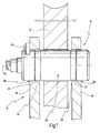
- Fig. 1 and 2 is a provided with the general reference numeral 10 load cell for measuring axial forces acting substantially transversely to an axis shown.
- the force transducer 10 is also referred to as the measuring axis.
- Fig. 1 the load cell 10 is shown by way of example in an installed position as a measuring axis for a cable wheel 12.
- the force transducer 10 are to be measured by the unillustrated rope on the measuring axis 10, which forms the axis of the cable wheel 12, acting transversely to the measuring axis 10 substantially axial forces, which may also consist in torsional forces.
- Fig. 1 is the force transducer 10 in a kind of receiving fork 14, which has two legs 16 and 18, defined therein holes 20 and 22.
- the force transducer 10 has according to Fig. 2 an axle core 24 extending along a longitudinal axis 26 of the force transducer 10.
- the axle forces to be measured act perpendicular to the longitudinal axis 26.
- the force transducer 10 also has a substantially over the length of the axle core 24 extending, the axle core 24 sheathing sleeve 28.
- the axle core 24 and the sleeve 28 are formed substantially cylindrically symmetrical.
- the sleeve 28 is fixedly connected to the axle core 24.
- the sleeve 28 is shrunk in the region of end portions 30 and 32 on the overall integrally formed axle core 24.
- the sleeve 28 has a first support zone 36 and a second support zone 38.
- the axle core 24 has in the region between the support zones 36 and 38 two load measuring zones for measuring the axle forces, specifically a first load measuring zone 42 and a second load measuring zone 44.
- each one or more, here schematically indicated force measuring devices 46 and 48 are arranged.
- the force measuring devices 46 and 48 are formed for example on the basis of strain gauges, detect the stresses, strains and shearing of the material of the axle core 24 in the force measuring zones 42 and 44 due to the axial forces to be measured by a change in resistance and convert it into an electrical signal.
- a connection 50 for connecting an electrical supply and signal transmission cable which is not shown, is provided on the force transducer 10, wherein for the preparation of the electrical connection with the force measuring means 46 and 48, a corresponding longitudinally extending blind hole 52 is formed for power lines.
- the axle core 24 has a smaller diameter than in its other areas, and in the force measuring zones 42 and 44, the axle core 24 is correspondingly spaced from the sleeve 28.
- the sleeve 28 has a first bending zone 54 and a second bending zone 56 in which the sleeve 28 is flexible in the direction substantially transverse to the longitudinal direction 26 of the axle core 24 with respect to the remaining portion of the sleeve 28 with less force, as will be described hereinafter.
- the bending zones 54 and 56 are formed approximately in the region of the force measuring zones 42 and 44 and between the support zones 36 and 38 of the sleeve 28.
- the bending zones 54 and 56 each form a kind of joint in the sleeve 28. While the bending zones 54 and 56 can be realized in particular by the sleeve 28th is one piece and in the region of the bending zones 54 and 56 has a lower material thickness than in the remaining region of the sleeve 28, the bending zones 54 and 56 of the sleeve 28 are realized as follows.
- the sleeve 28 is formed of three sleeve portions, namely a first (middle) sleeve portion 58, a second sleeve portion 60, which forms the one end portion 30 of the sleeve 28, and a third sleeve portion 62, which forms the other end portion 32 of the sleeve 28.
- Each of the sleeve sections 58, 60, 62 is attached by itself to the axle core 24, i. Shrunk in the present case.
- the sleeve portions 58, 60, 62 which are arranged one behind the other in the longitudinal direction 26 of the axle core 24 and abut each other, however, are not firmly connected to each other.
- the joint between the first sleeve portion 58 and the second sleeve portion 60 is located approximately in the region of the force measuring zone 42, and the joint between the first sleeve portion 58 and the third sleeve portion 62 is located approximately in the region of the Kraftmeßzone 44 of the axle 24th
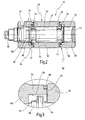
- the first sleeve portion 58 has, as in the enlarged detail in Fig. 3 can be seen better, at the end a first thin-walled bending section 64 and at the opposite end a likewise thin-walled second bending section 66.
- the bending portions 64 and 66 extend to the first sleeve portion 58 in full.
- the bending portions 64 and 66 are formed in the cross-section bellows, in the present Embodiment, they have approximately the shape of a U or Q on.
- the bending portions 64 and 66 which together with the multi-part of the sleeve 28, the bending zones 54 and 56 form, are located approximately in the region of the force measuring zones 42 and 44th
- the first bending section 64 is fixedly connected at its free end to a collar 68 formed on the axle core 24, which has a larger diameter than the force measuring zone 42, being welded to the collar 168 along a weld seam 70 in the exemplary embodiment shown. This ensures that the force measuring zone 42, which contains the force measuring or force 46, is hermetically sealed against the ingress of contaminants, moisture and the like.
- the second bending portion 66 of the first sleeve portion 58 is fixedly connected to a collar 72 of the axle core 24, in particular welded.
- the second sleeve section 60 has an end section 74 facing the first sleeve section 58, which engages over the bending section 64 of the first sleeve section 58 on the outside.
- the end portion 74 is for this purpose on its the bending portion 64 facing side 76 is rotated.
- the first sleeve portion 58 is not fixedly connected to the second sleeve portion 60, but the two sleeve portions 58 and 60 form a joint 78 along which the sleeve portions 58 and 60 are movable relative to each other. namely, substantially transversely to the longitudinal direction 26 of the force transducer 10th
- the joint 78 is correspondingly sealed by an O-ring seal 80, but not the flexibility imparted freedom of movement of the sleeve portions 58 and 60 relative to each other with special needs.
- the bending zones 54 and 56 of the sleeve 28 of the force transducer 10 now advantageously cause, for example, by the installation situation of the force transducer caused tension, which may have their cause, for example, in a non-parallelism or an axial offset of the holes 20 and 22 of the receiving fork 14, not on the Achskern transmitted 24, but are absorbed more or less alone from the sleeve 28 in the bending zones 54 and 56, whereby the installation situation, which is not changeable in the rule, measurement accuracy of the force transducer 10 is not affected.
- Fig. 4 is a relative to the force transducer 10 modified embodiment of a force transducer 10 'shown in fragmentary form.
- In Fig. 4 are parts or features that are the same or comparable to those of the force transducer 10, provided with the same reference numerals with a superscript. Only the differences of the force transducer 10 'to the force transducer 10 will be described below.
- the differences of the force transducer 10 'to the force transducer 10 relate to the configuration of the bending zones, as shown for the bending zone 54'.
- the bending zone 54 ' is formed by a bending section 64', which is preferably connected to the first sleeve section 58 'and which in turn is fastened with its free end by means of a weld seam 70' to the collar 68 'of the axle core 24'.
- the first sleeve portion 58 'in the region of the approach of the bending portion 64' by material recess, here in the form of a plan recess partially reset or machined so that the bending portion 64 'has a corresponding length which corresponds to the length of the force measuring zone 42'.
- the bending zone 54 ' forms a long, thin joint.
- the bending portion 64 ' is straight, that is not bellows-shaped, but can also be a bellows-like configuration as in the bending section 64 of the force transducer 10 are taken into consideration.
Landscapes
- Physics & Mathematics (AREA)
- Engineering & Computer Science (AREA)
- General Physics & Mathematics (AREA)
- General Health & Medical Sciences (AREA)
- Mechanical Engineering (AREA)
- Health & Medical Sciences (AREA)
- Biomedical Technology (AREA)
- Force Measurement Appropriate To Specific Purposes (AREA)
- Moulds For Moulding Plastics Or The Like (AREA)
- Golf Clubs (AREA)
- Measurement Of Force In General (AREA)
- External Artificial Organs (AREA)
- Paper (AREA)
Abstract
Description
Die Erfindung betrifft einen Kraftaufnehmer zum Messen von Achskräften, die im wesentlichen quer auf eine Achse wirken, insbesondere eine Meßachse, mit einem sich längs erstreckenden Achskern und einer sich über im wesentlichen die Länge des Achskerns erstreckenden, den Achskern ummantelnden Hülse, die fest mit dem Achskern verbunden ist, wobei die Hülse ferner zumindest zwei voneinander beabstandete Auflagezonen aufweist, und wobei schließlich der Achskern im Bereich zwischen den Auflagezonen zumindest eine Kraftmeßzone zum Messen der Achskräfte aufweist, in der zumindest eine Kraftmeßeinrichtung angeordnet ist.The invention relates to a force transducer for measuring axial forces which act substantially transversely to an axis, in particular a measuring axis, with a longitudinally extending axle core and extending over substantially the length of the axle core, the Achskern sheath sleeve fixed to the Achskern is connected, wherein the sleeve further comprises at least two spaced bearing zones, and wherein finally the axle core in the region between the support zones has at least one Kraftmeßzone for measuring the axial forces, in which at least one force measuring device is arranged.
Ein derartiger Kraftaufnehmer ist
Ein Kraftaufnehmer der eingangs genannten Art wird dazu verwendet, Kräfte zu messen, die im wesentlichen quer auf eine Achse oder Welle drehender Teile von Maschinen oder Anlagen wirken. Derartige Achskräfte können in einer rein radial auf die Achse wirkenden Kraft oder in einer Torsionskraft bestehen. Beispielsweise wird ein derartiger Kraftaufnehmer zum Messen von Achskräften bei Seilrollen verwendet, beispielsweise in Seilbahnen. Die Messung von Achskräften dient bei diesem Anwendungsfall insbesondere der Erfassung von Überbelastungen der Seilrollen, um Gefahrenzustände rechtzeitig erkennen zu können.A force transducer of the type mentioned is used to measure forces that act substantially transversely to an axis or shaft rotating parts of machinery or equipment. Such axial forces can exist in a purely radial force acting on the axis or in a torsional force. For example, such a force transducer is used for measuring axle forces in pulleys, for example in cable cars. The measurement of axle forces in this application, in particular the detection of overloading the pulleys in order to detect dangerous conditions in good time.
Wesentlicher Bestandteil der Kraftmessung ist der Achskern des Kraftaufnehmers, der im wesentlichen massiv ausgebildet ist. Der Achskern weist zumindest eine, üblicherweise zwei Kraftmeßzonen auf, in dem bzw. in denen jeweils zumindest ein Kraftmeßsystem angeordnet ist. Das Kraftmeßsystem erfaßt Scherkräfte, Dehnungen und Stauchungen im Achskern, und wandelt diese in meßbare Signale, üblicherweise elektrische Signale, zur Ermittlung der Kraft um. Beispielsweise weist das oder weisen die Kraftmeßsysteme Dehnungsmeßstreifen auf, die eine Kraftmessung über Widerstandsänderungen innerhalb einer oder mehrerer Brückenschaltungen ermöglichen.An essential component of the force measurement is the axle core of the force transducer, which is substantially solid. The axle core has at least one, usually two force measuring zones, in which or in each of which at least one force measuring system is arranged. The force measuring system detects shear forces, strains and compressions in the axle core, and converts these into measurable signals, usually electrical signals, to determine the force. For example, the force measuring system (s) has strain gauges that enable force measurement via resistance changes within one or more bridge circuits.
Das Kraftmeßsystem, beispielsweise in Form von Dehnungsmeßstreifen, wird dabei auf der Oberfläche des Achskerns in den Kraftmeßzonen aufgebracht. In den Kraftmeßzonen weist der Achskern üblicherweise eine geringere Querschnittsabmessung auf, so daß sich dort die durch die Achskräfte verursachten Scherungen, Dehnungen und Stauchungen ausbilden.The force measuring system, for example in the form of strain gauges, is applied to the surface of the axle core in the force measuring zones. In the force measuring zones, the axle core usually has a smaller cross-sectional dimension, so that the shear forces, strains and compressions caused by the axial forces are formed there.
Der aus dem zuvor genannten Dokument
Das oder die Kraftmeßsysteme müssen vor äußeren Einflüssen, beispielsweise Feuchtigkeit und Verschmutzung geschützt sein. Daher weisen derartige Kraftaufnehmer eine den Achskern im wesentlichen hermetisch abschließende Hülse auf, um das Eindringen von die Meßgenauigkeit beeinflussenden Verunreinigungen und Feuchtigkeit zu verhindern.The one or more force measuring systems must be protected against external influences, such as moisture and pollution. Therefore, such load cells have a core hermetically sealed to the axle core to prevent the ingress of impurities and moisture affecting the measurement accuracy.
Kraftaufnehmer zum Messen von Achskräften werden üblicherweise zu ihrem Einsatzzweck in eine Art Aufnahmegabel oder ähnliche Lager eingelegt, wie dies beispielsweise im Anwendungsfall des Kraftaufnehmers zum Messen von Achskräften einer Seilrolle der Fall ist. Die Hülse, die den Achskern umgibt, weist dazu im Bereich ihrer Längsenden Auflagezonen auf, über die der Kraftaufnehmer an seinem Einsatzort festgelegt ist. Hierbei besteht jedoch häufig das Problem, daß die gegenüberliegenden Lager, in denen der Kraftaufnehmer gelagert ist, nicht exakt miteinander fluchten oder nicht parallel sind. Beim Einbauen des Kraftaufnehmers kann es dabei zu Verspannungen des Kraftaufnehmers kommen, die von der Kraftmeßeinrichtung bzw. den Kraftmeßeinrichtungen erfaßt werden, ohne daß es sich hierbei um eine Achskraft handelt, die gemessen werden soll. Die durch die Einbausituation des Kraftaufnehmers verursachten Kräfte sind daher parasitäre Kräfte, die die tatsächliche Kraftmessung erheblich verfälschen können. Hierbei ist zu berücksichtigen,
daß Kraftmeßeinrichtungen auf der Basis von Dehnungsmeßstreifen bereits auf Scherungen, Dehnungen und Stauchungen im Submillimeterbereich ansprechen, und daß Fertigungstoleranzen der Aufnahmelager, in die die Kraftaufnehmer eingebaut werden, zumindest ebenfalls in dieser Größenordnung liegen.Force transducers for measuring axle forces are usually inserted for their intended use in a kind of receiving fork or similar bearings, as is the case for example in the application of the force transducer for measuring axial forces of a pulley. The sleeve, which surrounds the axle core, has for this purpose in the region of its longitudinal ends bearing zones, via which the load cell is fixed at its place of use. However, there is often the problem that the opposite bearings in which the force transducer is mounted, not exactly aligned with each other or are not parallel. When installing the force transducer, it can lead to tension of the force transducer, which are detected by the force measuring device or the force measuring without this being an axle force, which is to be measured. The forces caused by the installation situation of the force transducer are therefore parasitic forces that can significantly falsify the actual force measurement. It is important to take into account
that force measuring devices on the basis of strain gages already respond to shearing, strains and compressions in the submillimeter range, and that manufacturing tolerances of the receiving warehouse, in which the load cells are installed, at least also in this order of magnitude.
Beim Einbau des Kraftaufnehmers in nicht fluchtende oder nicht parallele Aufnahmen tritt zunächst eine Verspannung in der Hülse auf, die sich jedoch aufgrund der festen Verbindung mit dem Achskern auf diesen überträgt, so daß sich derartige, durch den Einbau des Kraftaufnehmers bedingte Verspannungen als parasitäre Kräfte auf das Kraftmeßsystem und damit auf die Genauigkeit der Kraftmessung negativ auswirken. Weitere parasitäre Kräfte, die die genaue Kraftmessung nachteilig beeinflussen, können auftreten, wenn die zu messende Kraft nicht exakt quer, sondern auch mit axialer Komponente in die Achse eingeleitet wird.When installing the force transducer in non-aligned or non-parallel recordings initially occurs a strain in the sleeve, which, however, due to the fixed connection with the axle core transmits to this, so that such, due to the installation of the force transducer tensions as parasitic forces the force measuring system and thus negatively affect the accuracy of the force measurement. Other parasitic forces that adversely affect the exact force measurement can occur when the force to be measured is not introduced exactly transversely, but also with an axial component in the axis.
Der Erfindung liegt daher die Aufgabe zugrunde, einen Kraftaufnehmer der eingangs genannten Art dahingehend weiterzubilden, daß die Meßgenauigkeit des Kraftaufnehmers weitgehend unabhängig von der Einbausituation ist.The invention is therefore the object of developing a force transducer of the type mentioned in that the measurement accuracy of the force transducer is largely independent of the installation situation.
Erfindungsgemäß wird diese Aufgabe hinsichtlich des eingangs genannten Kraftaufnehmers dadurch gelöst, daß die Hülse im Bereich zwischen den Auflagezonen zumindest eine Biegezone aufweist, in der die Hülse in Richtung im wesentlichen quer zur Längsrichtung des Achskerns zur Aufnahme von die Kraftmessung negativ beeinflussenden parasitären Kräften biegsam ist.According to the invention this object is achieved with respect to the force transducer mentioned above in that the sleeve has at least one bending zone in the region between the support zones, in which the sleeve is flexible in the direction substantially transversely to the longitudinal direction of the axle core for receiving the force measurement negatively influencing parasitic forces.
Durch die erfindungsgemäße Ausgestaltung des Kraftaufnehmers werden die Kraftmessung negativ beeinflussende parasitäre Kräfte von der Biegezone der Hülse aufgenommen, ohne daß diese sich auf die Kraftmeßzone des Achskerns auswirken können, zumindest nicht in dem Ausmaß, daß sie die Kraftmessung nachhaltig beeinträchtigen. Durch die Biegezone wird mit anderen Worten eine Art Gelenk in der Hülse gebildet. Eine Nichtparallelität der Aufnahmelager für den Kraftaufnehmer oder nicht exakt quer zur Längsrichtung des Achskerns angreifende Kräfte, die auch eine Axialkomponente besitzen, wirken sich somit nicht mehr, zumindest nicht mehr in dem Ausmaß auf die Kraftmessung nachteilig aus. Die Biegezone kann beispielsweise durch eine entsprechende Dünnwandigkeit der Hülse im Bereich der Kraftmeßzone gegenüber dem übrigen Bereich der Hülse oder durch eine mehrteilige Ausgestaltung der Hülse realisiert sein. Die Hülse ist im Bereich der Biegezone bereits bei geringerer Krafteinwirkung verbiegsam, als es der Achskern ist.Due to the inventive design of the force transducer, the force measurement negatively influencing parasitic forces are absorbed by the bending zone of the sleeve, without these can affect the Kraftmeßzone of the axle, at least not to the extent that they affect the force measurement sustainable. In other words, a kind of hinge is formed in the sleeve by the bending zone. A non-parallelism of the receiving bearing for the load cell or not exactly transversely to the longitudinal direction of the axle core attacking forces, which is also a Have axial component, thus no longer have an effect, at least not to the extent of the force measurement disadvantageous. The bending zone can be realized for example by a corresponding thin-walledness of the sleeve in the region of the force measuring zone with respect to the remaining region of the sleeve or by a multi-part design of the sleeve. The sleeve is bendable in the region of the bending zone even with less force than it is the axle core.
In einer bevorzugten Ausgestaltung ist die zumindest eine Biegezone im Bereich der zumindest einen Kraftmeßzone angeordnet.In a preferred embodiment, the at least one bending zone is arranged in the region of the at least one force measuring zone.
Hierbei ist von Vorteil, daß der Achskern in der Kraftmeßzone üblicherweise von der Hülse radial beabstandet ist, so daß sich eine Biegsamkeit der Hülse im Bereich der Kraftmeßzone besonders gut eignet, um an dieser Stelle eine Art Gelenk zu bilden, weil sich durch die Beabstandung des Achskerns von der Hülse im Bereich der Kraftmeßzone eine höhere Beweglichkeit der Hülse ergibt.It is advantageous that the axle core in the force measuring zone is usually radially spaced from the sleeve, so that a flexibility of the sleeve in the force measuring zone is particularly well suited to form at this point a kind of joint, because the spacing of the Achskerns of the sleeve in the region of the force measurement zone results in a higher mobility of the sleeve.
In diesem Zusammenhang ist es besonders bevorzugt, wenn die zumindest eine Biegezone sich über die gleiche axiale Länge erstreckt wie die Kraftmeßzone.In this context, it is particularly preferred if the at least one bending zone extends over the same axial length as the force measuring zone.
Diese Maßnahme hat den Vorteil, daß bei einer Biegung der Achse im Einsatz die Kraftmeßzone durch die Hülse im wesentlichen den gleichen Verformungsweg besitzt, wodurch unerwünschte Hystereseeffekte vermieden werden können. Durch diese Ausgestaltung werden die freie Zone von Hülse und Achskern aneinander angeglichen, was ihren Verformungsweg angeht.This measure has the advantage that when the axis is bent in use, the force measuring zone through the sleeve has essentially the same deformation path, whereby undesired hysteresis effects can be avoided. By this configuration, the free zone of sleeve and axle core are aligned with each other, as far as their deformation path.
In einer weiteren bevorzugten Ausgestaltung weist die Hülse in der Biegezone eine geringere Materialstärke auf als im übrigen Bereich der Hülse.In a further preferred embodiment, the sleeve in the bending zone has a lower material thickness than in the remaining region of the sleeve.
Hierbei ist von Vorteil, daß die Hülse insgesamt einstückig ausgebildet werden kann, so daß sie die Funktion einer hermetischen Abdichtung des Achskerns ohne zusätzliche Abdichtungsmaßnahmen erfüllen kann, wodurch die Produktionskosten einer solchen Hülse vorteilhafterweise gering gehalten werden können. Beispielsweise kann die Hülse in der Biegezone eine oder mehrere umfängliche radial eingebrachte Nuten aufweisen, um die geringere Materialstärke zu erhalten.It is advantageous that the sleeve can be integrally formed as a whole, so that they can fulfill the function of a hermetic seal of the axle without additional sealing measures, whereby the production cost of such a sleeve can be advantageously kept low. For example, in the bending zone, the sleeve can have one or more circumferential radially inserted grooves in order to obtain the lower material thickness.
In einer weiteren bevorzugten Ausgestaltung ist die Hülse in der Biegezone im wesentlichen elastisch biegsam.In a further preferred embodiment, the sleeve in the bending zone is substantially elastically flexible.
Hierbei ist von Vorteil, daß sich die Hülse nach ihrem Ausbau wieder selbständig zurückstellt, ohne daß eine bleibende Verformung der Hülse auftritt, so daß der Kraftaufnehmer dann anschließend an einem anderen Einsatzort wieder verwendet werden kann.The advantage here is that the sleeve automatically resets itself after its removal, without a permanent deformation of the sleeve occurs, so that the force transducer can then be used again at another site.
In einer weiteren bevorzugten Ausgestaltung ist die Biegezone im Querschnitt balgartig ausgebildet.In a further preferred embodiment, the bending zone is formed in a bellows-like cross-section.
Diese Maßnahme hat den Vorteil, daß die "Gelenkigkeit" bzw. Biegeverformbarkeit besonders ausgeprägt werden kann, wodurch besonders starke Verspannungen aufgrund einer Nichtparallelität der Aufnahmelager für den Kraftaufnehmer bzw. eines Versatzes dieser Lager von der Hülse ohne negativen Einfluß auf die Kraftmeßzone aufgenommen werden können, ebenso wie nicht exakt quer zur Längsrichtung der Achse eingeleitete Kräfte, die eine Komponente in Längsrichtung des Achskerns aufweisen. Im einfachsten Fall weist die Biegezone im Querschnitt die Form eines oder mehrerer um 180° gegeneinander versetzter U auf.This measure has the advantage that the "articulation" or Biegeverformbarkeit can be particularly pronounced, whereby particularly strong tension due to non-parallelism of the receiving bearing for the load cell or an offset of these bearings can be absorbed by the sleeve without negative impact on the force measuring zone as well as not exactly Forces introduced transversely to the longitudinal direction of the axis, which have a component in the longitudinal direction of the axle core. In the simplest case, the bending zone in cross section in the form of one or more by 180 ° staggered U on.
In einer weiteren bevorzugten Ausgestaltung ist die zumindest eine Biegezone im Querschnitt gerade ausgebildet.In a further preferred embodiment, the at least one bending zone is straight in cross section.
Die Ausgestaltung hat herstellungstechnisch gegenüber der balgartigen Ausgestaltung der Biegezone Vorteile, da die Geometrie der Biegezone einfacher ist als bei einer balgartigen Ausgestaltung der Biegezone.The design has manufacturing technology advantages over the bellows-like configuration of the bending zone advantages, since the geometry of the bending zone is easier than in a bellows-like configuration of the bending zone.
Weiterhin ist es bevorzugt, wenn die Hülse aus zumindest zwei Hülsenabschnitten gebildet ist, die in Längsrichtung des Achskerns hintereinander und aneinander anstoßend angeordnet sind, ohne miteinander fest verbunden zu sein, wobei ein erster Hülsenabschnitt einen Biegeabschnitt aufweist, der dünnwandig ausgebildet ist, und dessen freies Ende mit dem Achskern fest verbunden ist.Furthermore, it is preferred if the sleeve is formed from at least two sleeve sections, which are arranged one behind the other and abutting one another in the longitudinal direction of the axle, without being firmly connected to each other, wherein a first sleeve portion has a bent portion, which is thin-walled, and the free End is firmly connected to the axle core.
Die mehrteilige Ausgestaltung der Hülse hat gegenüber einer einteiligen Ausgestaltung den Vorteil, daß die zur Ausgestaltung der Biegezone bzw. des Biegeabschnittes erforderlichen maschinellen Bearbeitungsvorgänge einfacher sind, da die Bearbeitungsvorgänge an den Enden der Hülsenabschnitte vorgenommen werden können. Des weiteren hat diese Maßnahme den Vorteil, daß die "Gelenkigkeit" der Biegezone durch die mehrteilige Ausgestaltung noch verbessert werden kann, wodurch die Meßgenauigkeit des Kraftaufnehmers noch weiter verbessert wird. Dadurch, daß der Biegeabschnitt mit dem Achskern fest verbunden ist, wird des weiteren trotz der mehrteiligen Ausgestaltung eine hermetische Abdichtung der Hülse gegen den Achskern erreicht, wodurch die Kraftmeßzone sicher gegen äußere Einflüsse, wie Verunreinigungen, Feuchtigkeit, die die Meßgenauigkeit ebenfalls beeinflussen können, geschützt ist.The multi-part design of the sleeve has the advantage over a one-part design that the machining operations required to form the bending zone or the bending section are simpler, since the machining operations can be carried out at the ends of the sleeve sections. Furthermore, this measure has the advantage that the "flexibility" of the bending zone can be improved by the multi-part design, whereby the measurement accuracy of the force transducer is further improved. The fact that the bending section is firmly connected to the axle core, is Furthermore, in spite of the multi-part design, a hermetic seal of the sleeve against the axle core achieved, whereby the force measuring zone is protected against external influences, such as contaminants, moisture, which can also affect the accuracy of measurement.
Vorzugsweise ist das freie Ende mit einem Bund am Achskern umfänglich verschweißt.Preferably, the free end is circumferentially welded to the axle core.
In einer weiteren bevorzugten Ausgestaltung übergreift ein Endabschnitt eines zweiten Hülsenabschnitts den Biegeabschnitt des ersten Hülsenabschnitts, und der Endabschnitt ist gegenüber dem ersten Hülsenabschnitt abgedichtet.In another preferred embodiment, an end portion of a second sleeve portion engages over the bending portion of the first sleeve portion, and the end portion is sealed from the first sleeve portion.
Diese Maßnahme hat den Vorteil, daß sich keine Verunreinigungen zwischen dem ersten Hülsenabschnitt und dem zweiten Hülsenabschnitt ablagern können. Derartige Verunreinigungen könnten bei entsprechender Konsistenz verhärten und die Scherbewegung der Hülsenabschnitte relativ zueinander behindern und damit die Meßgenauigkeit wieder negativ beeinflussen. Die Abdichtung kann beispielsweise mittels einer oder mehreren O-Ringen ausgeführt sein.This measure has the advantage that no contamination between the first sleeve portion and the second sleeve portion can be deposited. Such impurities could harden with appropriate consistency and impede the shearing movement of the sleeve sections relative to each other and thus adversely affect the accuracy again. The seal can be carried out, for example, by means of one or more O-rings.
In einer weiteren bevorzugten Ausgestaltung ist der Endabschnitt des zweiten Hülsenabschnitts auf seiner dem Biegeabschnitt zugewandten Seite freigedreht.In a further preferred embodiment, the end portion of the second sleeve portion is freely rotated on its side facing the bending section.
Hierbei ist von Vorteil, daß die Außenkontur der gesamten Hülse trotz des mehrteiligen Aufbaus und dem vorgesehenen Biegeabschnitt insgesamt gleichmäßig ohne Stufen und Durchmesseränderungen ausgeführt werden kann.It is advantageous that the outer contour of the entire sleeve despite the multi-part construction and the intended bending section can be performed evenly without steps and changes in diameter.
In einer weiteren besonders bevorzugten Ausgestaltung weist die Hülse zumindest zwei Biegezonen auf.In a further particularly preferred embodiment, the sleeve has at least two bending zones.
Durch das Vorsehen von zumindest zwei Biegezonen können aufgrund von Nichtparallelitäten der Aufnahmelager bzw. von schräg in die Achse eingeleiteten Kräften noch besser von der Hülse kompensiert werden, ohne daß sich die Kräfte auf die Kraftmeßzonen und damit nachteilig auf die genaue Kraftmessung auswirken, weil die Hülse zwei "Gelenke" besitzt.Due to the provision of at least two bending zones due to non-parallelism of the receiving camp or obliquely introduced into the axis forces can be better compensated by the sleeve without the forces on the force measuring and thus adversely affect the exact force measurement, because the sleeve has two "joints".
Des weiteren ist es in diesem Zusammenhang bevorzugt, wenn die Hülse aus drei Hülsenabschnitten gebildet ist.Furthermore, it is preferred in this context if the sleeve is formed from three sleeve sections.
Hierbei ergeben sich zusätzlich die bereits zuvor genannten Vorteile der relativen Beweglichkeit der einzelnen Hülsenabschnitte zueinander, wobei diese relative Beweglichkeit in einer Scherbewegung der einzelnen Hülsenabschnitte zueinander besteht.This results in addition to the already mentioned advantages of the relative mobility of the individual sleeve sections to each other, this relative mobility consists in a shearing movement of the individual sleeve sections to each other.
Weitere Vorteile und Merkmale ergeben sich aus der nachfolgenden Beschreibung und der beigefügten Zeichnung.Further advantages and features will become apparent from the following description and the accompanying drawings.
Es versteht sich, daß die vorstehend genannten und nachstehend noch zu erläuternden Merkmale nicht nur in der jeweils angegeben Kombination, sondern auch in anderen Kombinationen oder in Alleinstellung verwendbar sind, ohne den Rahmen der vorliegenden Erfindung zu verlassen.It is understood that the features mentioned above and those yet to be explained not only in the combination given, but also in other combinations or alone, without departing from the scope of the present invention.
Ausführungsbeispiele der Erfindung sind in der Zeichnung dargestellt und werden mit Bezug auf diese hiernach näher beschrieben. Es zeigen:
- Fig. 1
- eine Seitenansicht eines Kraftaufnehmers zum Messen von Achskräften in einer beispielhaften Einbausituation bei einem Seilrad, das teilweise im Schnitt dargestellt ist;
- Fig. 2
- einen Längsschnitt durch den Kraftaufnehmer in
Fig. 1 ; - Fig. 3
- eine vergrößerte Darstellung des Ausschnitts X in
Fig. 2 ; und - Fig. 4
- eine
Fig. 3 entsprechende Darstellung eines Ausschnitts eines Kraftaufnehmers gemäß eines weiteren Ausführungsbeispiels.
- Fig. 1
- a side view of a force transducer for measuring axle forces in an exemplary installation situation in a cable wheel, which is partially shown in section;
- Fig. 2
- a longitudinal section through the force transducer in
Fig. 1 ; - Fig. 3
- an enlarged view of the section X in
Fig. 2 ; and - Fig. 4
- a
Fig. 3 corresponding representation of a section of a force transducer according to another embodiment.
In
In
Gemäß
Der Kraftaufnehmer 10 weist gemäß
Der Kraftaufnehmer 10 weist weiterhin eine sich über im wesentlichen die Länge des Achskerns 24 erstreckende, den Achskern 24 ummantelnde Hülse 28 auf. Der Achskern 24 und die Hülse 28 sind im wesentlichen zylindersymmetrisch ausgebildet.The
Die Hülse 28 ist mit dem Achskern 24 fest verbunden. Dazu ist die Hülse 28 im Bereich von Endabschnitten 30 und 32 auf den insgesamt einstückig ausgebildeten Achskern 24 aufgeschrumpft.The
Im Bereich ihrer Längsenden weist die Hülse 28 eine erste Auflagezone 36 und eine zweite Auflagezone 38 auf. Über die Auflagezonen 36 und 38 ist der Kraftaufnehmer 10 gemäß
Der Achskern 24 weist im Bereich zwischen den Auflagezonen 36 und 38 zwei Kraftmeßzonen zum Messen der Achskräfte auf, und zwar eine erste Kraftmeßzone 42 und eine zweite Kraftmeßzone 44.The
In den Kraftmeßzonen 42 und 44 ist jeweils eine oder sind jeweils mehrere, hier schematisch angedeutete Kraftmeßeinrichtungen 46 und 48 angeordnet. Die Kraftmeßeinrichtungen 46 und 48 sind beispielsweise auf der Basis von Dehnungsmeßstreifen ausgebildet, die Spannungen, Dehnungen und Scherungen des Materials des Achskerns 24 in den Kraftmeßzonen 42 und 44 infolge der zu messenden Achskräfte durch eine Widerstandsänderung detektieren und in ein elektrisches Signal umwandeln. Dazu ist an dem Kraftaufnehmer 10 ein Anschluß 50 zum Anschließen eines elektrischen Versorgungs- und Signalübertragungskabels, das nicht dargestellt ist, vorgesehen, wobei zur Herstellung der elektrischen Verbindung mit den Kraftmeßeinrichtungen 46 und 48 eine entsprechende sich längserstreckende Sacklochbohrung 52 für Stromleitungen ausgebildet ist.In the
In den Kraftmeßzonen 42 und 44 weist der Achskern 24 einen geringeren Durchmesser auf als in seinen übrigen Bereichen, und in den Kraftmeßzonen 42 und 44 ist der Achskern 24 entsprechend von der Hülse 28 beabstandet. Durch die zu messenden Achskräfte bewirkte Dehnungen und Stauchungen des Materials des Achskerns 24 treten somit in den Kraftmeßzonen 42 und 44 ausgeprägt auf, wodurch die Kraftmeßeinrichtungen 46 und 48 diese Dehnungen und Stauchungen mit hoher Empfindlichkeit erfassen können.In the
Die Hülse 28 weist eine erste Biegezone 54 und eine zweite Biegezone 56 auf, in der die Hülse 28 in Richtung im wesentlichen quer zur Längsrichtung 26 des Achskerns 24 gegenüber dem übrigen Bereich der Hülse 28 mit geringerer Kraft biegsam ist, wie hiernach näher beschrieben wird.The
Die Biegezonen 54 und 56 sind etwa im Bereich der Kraftmeßzonen 42 und 44 und zwischen den Auflagezonen 36 und 38 der Hülse 28 ausgebildet. Die Biegezonen 54 und 56 bilden jeweils eine Art Gelenk in der Hülse 28. Während die Biegezonen 54 und 56 insbesondere dadurch realisiert werden können, daß die Hülse 28 einstückig ist und im Bereich der Biegezonen 54 und 56 eine geringere Materialstärke aufweist als im übrigen Bereich der Hülse 28, sind die Biegezonen 54 und 56 der Hülse 28 wie folgt realisiert.The bending
Die Hülse 28 ist aus drei Hülsenabschnitten gebildet, und zwar einem ersten (mittleren) Hülsenabschnitt 58, einem zweiten Hülsenabschnitt 60, der den einen Endabschnitt 30 der Hülse 28 bildet, und einem dritten Hülsenabschnitt 62, der den anderen Endabschnitt 32 der Hülse 28 bildet.The
Jeder der Hülsenabschnitte 58, 60, 62 ist für sich an dem Achskern 24 befestigt, d.h. im vorliegenden Fall aufgeschrumpft. Die Hülsenabschnitte 58, 60, 62, die in Längsrichtung 26 des Achskerns 24 hintereinander angeordnet sind und aneinander anstoßen, sind jedoch untereinander nicht fest miteinander verbunden. Die Stoßstelle zwischen dem ersten Hülsenabschnitt 58 und dem zweiten Hülsenabschnitt 60 befindet sich etwa im Bereich der Kraftmeßzone 42, und die Stoßstelle zwischen dem ersten Hülsenabschnitt 58 und dem dritten Hülsenabschnitt 62 befindet sich etwa im Bereich der Kraftmeßzone 44 des Achskerns 24.Each of the
Der erste Hülsenabschnitt 58 weist, wie in der Ausschnittsvergrößerung in
Die Biegeabschnitte 64 und 66, die zusammen mit der Mehrteiligkeit der Hülse 28 die Biegezonen 54 und 56 bilden, befinden sich etwa im Bereich der Kraftmeßzonen 42 bzw. 44.The bending
Der erste Biegeabschnitt 64 ist mit seinem freien Ende mit einem am Achskern 24 ausgebildeten Bund 68, der einen größeren Durchmesser aufweist als die Kraftmeßzone 42, fest verbunden, indem er im gezeigten Ausführungsbeispiel mit dem Bund 168 entlang einer Schweißnaht 70 verschweißt ist. Hierdurch wird erreicht, daß die Kraftmeßzone 42, die die Kraftmeßeinrichtung bzw. Kraftmeßeinrichtungen 46 enthält, gegen das Eindringen von Verunreinigungen, Feuchtigkeit und dgl. hermetisch dicht geschützt ist.The
Entsprechend ist auch der zweite Biegeabschnitt 66 des ersten Hülsenabschnitts 58 mit einem Bund 72 des Achskerns 24 fest verbunden, insbesondere verschweißt.Accordingly, the
Der zweite Hülsenabschnitt 60 weist einen dem ersten Hülsenabschnitt 58 zugewandten Endabschnitt 74 auf, der den Biegeabschnitt 64 des ersten Hülsenabschnitts 58 außenseitig übergreift. Der Endabschnitt 74 ist dazu auf seiner dem Biegeabschnitt 64 zugewandten Seite 76 freigedreht. Wie bereits erwähnt, ist der erste Hülsenabschnitt 58 mit dem zweiten Hülsenabschnitt 60 nicht fest verbunden, sondern die beiden Hülsenabschnitte 58 und 60 bilden eine Stoßstelle 78, entlang der die Hülsenabschnitte 58 und 60 relativ zueinander beweglich sind, und zwar im wesentlichen quer zur Längsrichtung 26 des Kraftaufnehmers 10.The
Um ein Eindringen von Verunreinigungen in den Bereich des Biegeabschnitts 64 zwischen den Hülsenabschnitten 58 und 60 zu vermeiden, ist die Stoßstelle 78 entsprechend durch eine O-Ringdichtung 80 abgedichtet, die jedoch nicht die durch die Biegsamkeit verliehene freie Beweglichkeit der Hülsenabschnitte 58 und 60 relativ zueinander behindert.In order to prevent ingress of contaminants into the region of the
Die zuvor mit Bezug auf den Biegeabschnitt 64 und den zweiten Hülsenabschnitt 60 erfolgte Beschreibung gilt in entsprechender Weise auch für den zweiten Biegeabschnitt 66 und den dritten Hülsenabschnitt 62, wie sich aus der Darstellung in
Die Biegezonen 54 und 56 der Hülse 28 des Kraftaufnehmers 10 bewirken nun vorteilhafterweise, daß sich beispielsweise durch die Einbausituation des Kraftaufnehmers verursachte Verspannungen, die beispielsweise in einer Nichtparallelität oder einem Achsenversatz der Bohrungen 20 und 22 der Aufnahmegabel 14 ihre Ursache haben kann, nicht auf den Achskern 24 übertragen, sondern mehr oder weniger allein von der Hülse 28 in den Biegezonen 54 und 56 aufgenommen werden, wodurch die Einbausituation, die in der Regel nicht veränderbar ist, Meßgenauigkeit des Kraftaufnehmers 10 nicht beeinträchtigt.The bending
In
Die Unterschiede des Kraftaufnehmers 10' zu dem Kraftaufnehmer 10 beziehen sich auf die Ausgestaltung der Biegezonen, wie für die Biegezone 54' dargestellt ist. Die Biegezone 54' erstreckt sich in Längsrichtung des Kraftaufnehmers 10 über die gleiche Länge wie die Kraftmeßzone 42', in der die Kraftmeßeinrichtung 46' angeordnet ist.The differences of the force transducer 10 'to the
Die Biegezone 54' wird durch einen mit dem ersten Hülsenabschnitt 58' vorzugsweise verbundenen Biegeabschnitt 64' gebildet, der wiederum mit seinem freien Ende mittels einer Schweißnaht 70' an den Bund 68' des Achskerns 24' befestigt ist.The bending zone 54 'is formed by a bending section 64', which is preferably connected to the first sleeve section 58 'and which in turn is fastened with its free end by means of a weld seam 70' to the collar 68 'of the axle core 24'.
Um zu erreichen, daß sich die Biegezone 54' über die gleiche oder im wesentlichen die gleiche Länge erstreckt wie die Kraftmeßzone 42', ist der erste Hülsenabschnitt 58' im Bereich des Ansatzes des Biegeabschnittes 64' durch Materialaussparung, hier in Form eines Planeinstichs teilweise zurückgesetzt bzw. freigearbeitet, so daß der Biegeabschnitt 64' eine entsprechende Länge aufweist, die der Länge der Kraftmeßzone 42' entspricht. Auf diese Weise bildet die Biegezone 54' ein langes, dünnes Gelenk.In order to achieve that the bending zone 54 'extends over the same or substantially the same length as the force measuring zone 42', the first sleeve portion 58 'in the region of the approach of the bending portion 64' by material recess, here in the form of a plan recess partially reset or machined so that the bending portion 64 'has a corresponding length which corresponds to the length of the force measuring zone 42'. In this way, the bending zone 54 'forms a long, thin joint.
In dem gezeigten Ausführungsbeispiel ist der Biegeabschnitt 64' gerade, d.h. nicht balgartig ausgebildet, jedoch kann auch eine balgartige Ausgestaltung wie bei dem Biegeabschnitt 64 des Kraftaufnehmers 10 in Betracht gezogen werden.In the embodiment shown, the bending portion 64 'is straight, that is not bellows-shaped, but can also be a bellows-like configuration as in the
Claims (12)
- A force transducer for measuring axial forces which act essentially transversely on an axis, in particular on a measuring axis, comprising an axis core (24; 24') extending longitudinally, and a sleeve (28; 28') extending substantially over the length of the axis core (24; 24'), and jacketing the axis core (24; 24'), which sleeve is fixedly connected with the axis core (24; 24'), wherein the sleeve (28; 28') further has at least two bearing zones (36, 38; 36') spaced apart from one another, and wherein finally the axis core (24; 24') has at least one force measuring zone (42, 44; 42') in the region between the bearing zones (36, 38; 36') for measuring the axial forces, in which force measuring zone at least one force measuring device (46, 48; 46') is arranged, characterized in that the sleeve (28; 28') has at least one bending zone (54, 56; 54') in the region between the bearing zones (36, 38; 36'), in which bending zone the sleeve (28; 28') is bendable in direction substantially transverse to the longitudinal direction to the axis core (24; 24') for absorbing parasitic forces having a negative impact on the force measuring.
- The force transducer of claim 1, characterized in that the at least one bending zone (54, 56; 54') is arranged in the region of the at least one force measuring zone (42, 44; 42').
- The force transducer of claim 2, characterized in that the at least one bending zone (54') extends over the same axial length as the force measuring zone (42').
- The force transducer of any one of claims 1 through 3, characterized in that the sleeve (28; 28') has a lower material thickness in the bending zone (54, 56; 54') than in the remaining region of the sleeve (28; 28').
- The force transducer of any one of claims 1 through 4, characterized in that the sleeve (28; 28') is substantially elastically bendable in the bending zone (54, 56; 54').
- The force transducer of any one of claims 1 through 5, characterized in that the bending zone (54, 56) is configured in bellows-like fashion in cross-section.
- The force transducer of any one of claims 1 through 5, characterized in that the bending zone (54') is configured straight in cross-section.
- The force transducer of any one of claims 1 through 7, characterized in that the sleeve (28; 28') is formed by at least two sleeve portions (58, 60, 62; 58', 60'), which are arranged one after another and adjacent to one another in longitudinal direction of the axis core (24; 24'), without being fixedly connected with one another, wherein a first sleeve portion (58; 58') has at least one bending portion (64, 66; 64') configured in thin-walled fashion, a free end of which is fixedly connected to the axis core (24; 24').
- The force transducer of claim 8, characterized in that an end portion (74; 74') of a second sleeve portion (60, 62; 62') lapps over the bending portion (64, 66; 64') of the first sleeve portion (58; 58') on an outer side and is sealed against the first sleeve portion (58; 58').
- The force transducer of claim 9, characterized in that the end portion (74; 74') of the second sleeve portion (60, 62; 60') is turned free on a lathe on its side facing the bending portion (64, 66; 64').
- The force transducer of anyone of claims 1 through 10, characterized in that the sleeve (28; 28') has at least two bending zones (54, 56; 54').
- The force transducer of claim 11, characterized in that the sleeve (28; 28') is formed by at least three sleeve portions (58, 60, 62; 58', 60').
Applications Claiming Priority (3)
| Application Number | Priority Date | Filing Date | Title |
|---|---|---|---|
| DE10245768 | 2002-09-25 | ||
| DE10245768A DE10245768B8 (en) | 2002-09-25 | 2002-09-25 | Force transducer for measuring axle forces |
| PCT/EP2003/010644 WO2004031712A1 (en) | 2002-09-25 | 2003-09-25 | Force transducer for measuring shaft forces |
Publications (2)
| Publication Number | Publication Date |
|---|---|
| EP1543305A1 EP1543305A1 (en) | 2005-06-22 |
| EP1543305B1 true EP1543305B1 (en) | 2009-09-02 |
Family
ID=31984317
Family Applications (1)
| Application Number | Title | Priority Date | Filing Date |
|---|---|---|---|
| EP03770950A Expired - Lifetime EP1543305B1 (en) | 2002-09-25 | 2003-09-25 | Force transducer for measuring shaft forces |
Country Status (5)
| Country | Link |
|---|---|
| EP (1) | EP1543305B1 (en) |
| AT (1) | ATE441842T1 (en) |
| AU (1) | AU2003280342A1 (en) |
| DE (2) | DE10245768B8 (en) |
| WO (1) | WO2004031712A1 (en) |
Families Citing this family (13)
| Publication number | Priority date | Publication date | Assignee | Title |
|---|---|---|---|---|
| DE102005045024B4 (en) * | 2005-09-12 | 2015-09-10 | EBM Brosa Messgeräte GmbH & Co. KG | Modular measuring axis |
| US7644636B2 (en) | 2008-01-18 | 2010-01-12 | Honeywell International Inc. | Load pin brake cell apparatus |
| DE102009021999A1 (en) * | 2008-05-19 | 2010-02-25 | Hirschmann Automation And Control Gmbh | Device for avoiding a negative load in a load measuring pin |
| EP2362201B1 (en) | 2010-02-25 | 2016-02-10 | Brosa AG | Power measurement sleeve and power measurement device |
| EP2362200B1 (en) | 2010-02-25 | 2015-05-27 | Brosa AG | Power measurement sleeve and power measurement device |
| ITRM20130404A1 (en) * | 2013-07-11 | 2015-01-12 | Deltatech Di Fondriest Ivan Giovann I | METHOD FOR THE DIAGNOSIS OF FUNCTIONING OF A RAILWAY DEVIATOA, AND ITS DIAGNOSTIC SYSTEM. |
| DE102014109301B3 (en) * | 2014-07-03 | 2015-09-10 | Brosa Ag | Scissor-based load cell system with overload protection |
| DE102015102072B3 (en) * | 2015-02-13 | 2016-05-19 | Brosa Ag | Force transducer system for the simultaneous determination of forces acting from different directions |
| DE102016121259B4 (en) | 2016-11-07 | 2018-07-12 | Brosa Ag | Scissor-based measuring axis with overload protection |
| DE102017104758B4 (en) | 2017-03-07 | 2018-09-20 | Brosa Ag | Force transducer system for measuring shear forces on a crane roller head |
| DE102017110229B4 (en) * | 2017-05-11 | 2021-10-14 | Brosa Ag | Force measuring sleeve for multiple force measurements |
| DE102017111097B4 (en) | 2017-05-22 | 2020-08-06 | Brosa Ag | Redundant force measuring axis with spatially separated measuring arrangements |
| DE102017126182B4 (en) | 2017-11-09 | 2023-01-19 | Brosa Ag | Force measuring device with dynamic compensation |
Family Cites Families (7)
| Publication number | Priority date | Publication date | Assignee | Title |
|---|---|---|---|---|
| SE7510442L (en) * | 1975-09-18 | 1977-03-19 | Kurt Eilert Johansson | LEAF SPRING MOUNT WITH VAG |
| CH598687A5 (en) * | 1976-08-25 | 1978-05-12 | Comet Ges Fuer Elektronische R | |
| DE2807734A1 (en) * | 1977-02-28 | 1978-08-31 | Philips Nv | FORCE KNIFE |
| DE3111434C2 (en) * | 1981-03-24 | 1983-01-05 | Skf Kugellagerfabriken Gmbh, 8720 Schweinfurt | Device for measuring the axial force in a shaft supported by roller bearings |
| JPS60102536A (en) * | 1983-11-09 | 1985-06-06 | Mitsubishi Heavy Ind Ltd | Axle-load measuring balance |
| US4899599A (en) * | 1987-12-07 | 1990-02-13 | Magnetic Power Systems, Inc. | Strain force sensor means |
| DE3842037A1 (en) * | 1988-12-14 | 1990-06-28 | Wabco Westinghouse Fahrzeug | DEVICE FOR DETECTING THE AXIAL FORCE OF A TOW BAR COUPLING |
-
2002
- 2002-09-25 DE DE10245768A patent/DE10245768B8/en not_active Expired - Fee Related
-
2003
- 2003-09-25 EP EP03770950A patent/EP1543305B1/en not_active Expired - Lifetime
- 2003-09-25 WO PCT/EP2003/010644 patent/WO2004031712A1/en not_active Application Discontinuation
- 2003-09-25 AU AU2003280342A patent/AU2003280342A1/en not_active Abandoned
- 2003-09-25 DE DE50311873T patent/DE50311873D1/en not_active Expired - Lifetime
- 2003-09-25 AT AT03770950T patent/ATE441842T1/en not_active IP Right Cessation
Also Published As
| Publication number | Publication date |
|---|---|
| EP1543305A1 (en) | 2005-06-22 |
| AU2003280342A1 (en) | 2004-04-23 |
| DE10245768A1 (en) | 2004-04-08 |
| ATE441842T1 (en) | 2009-09-15 |
| DE10245768B4 (en) | 2004-11-18 |
| DE10245768B8 (en) | 2005-02-10 |
| WO2004031712A1 (en) | 2004-04-15 |
| DE50311873D1 (en) | 2009-10-15 |
Similar Documents
| Publication | Publication Date | Title |
|---|---|---|
| DE102016010551B3 (en) | Torque sensor with radial elastic torque transmission | |
| EP1543305B1 (en) | Force transducer for measuring shaft forces | |
| EP2981796B1 (en) | Force-measuring device | |
| DE102016010552B3 (en) | Torque sensor with sealing membrane | |
| DE102016010549A1 (en) | Torque sensor with shunt spokes | |
| EP3114449A1 (en) | Component with at least one measuring element comprising a sensor | |
| DE4218949A1 (en) | Radial or axial bearing with force measurement - connects bearing ring directly, or roller bearing indirectly via intermediate member, with force measuring film sensor. | |
| EP1583943B1 (en) | Force transducer for measuring axial forces | |
| EP0239563B1 (en) | Measurement transducer | |
| EP1807687B1 (en) | Force sensing element | |
| EP1415134B1 (en) | Device for measuring loads applied to rotating components | |
| DE2631698C2 (en) | Force transducer | |
| EP1922533A1 (en) | Modular construction measurement axle | |
| DE10302352B4 (en) | Force transducer for measuring axle forces | |
| WO2003031090A1 (en) | Device for detecting stress distribution of metal bands loaded by band tension | |
| EP1617196B1 (en) | Force and /or torque sensor | |
| EP0621469B1 (en) | Tensile force measuring apparatus | |
| DE102004033925A1 (en) | Torque measurement system for machinery has hollow body with cylindrical bore in central portion and tapered sides forming thin walled square-section central portion with strain gauges attached to it | |
| EP2963403A1 (en) | Force transducer system based on the shearing principle with overload protection | |
| DE10203872B4 (en) | Force transducers for measuring pressure or shear forces | |
| DE20300942U1 (en) | Axle force sensor for cable cars has recess to reduce hysteresis | |
| WO2016034283A1 (en) | Force measuring device | |
| DE20300940U1 (en) | Force transducer for measuring axle loads e.g. in rotating parts or systems such as pulleys, has sleeve whose end is free in region of loading zone | |
| DE1955450C3 (en) | Strain resistance transmitter for measuring forces | |
| EP1637856A2 (en) | Device for measuring rotational moment |
Legal Events
| Date | Code | Title | Description |
|---|---|---|---|
| PUAI | Public reference made under article 153(3) epc to a published international application that has entered the european phase |
Free format text: ORIGINAL CODE: 0009012 |
|
| 17P | Request for examination filed |
Effective date: 20050323 |
|
| AK | Designated contracting states |
Kind code of ref document: A1 Designated state(s): AT BE BG CH CY CZ DE DK EE ES FI FR GB GR HU IE IT LI LU MC NL PT RO SE SI SK TR |
|
| AX | Request for extension of the european patent |
Extension state: AL LT LV MK |
|
| DAX | Request for extension of the european patent (deleted) | ||
| RIN1 | Information on inventor provided before grant (corrected) |
Inventor name: FUTTERER, BERND Inventor name: PFEFFER, OTTO |
|
| 17Q | First examination report despatched |
Effective date: 20070201 |
|
| GRAP | Despatch of communication of intention to grant a patent |
Free format text: ORIGINAL CODE: EPIDOSNIGR1 |
|
| GRAS | Grant fee paid |
Free format text: ORIGINAL CODE: EPIDOSNIGR3 |
|
| GRAA | (expected) grant |
Free format text: ORIGINAL CODE: 0009210 |
|
| AK | Designated contracting states |
Kind code of ref document: B1 Designated state(s): AT BE BG CH CY CZ DE DK EE ES FI FR GB GR HU IE IT LI LU MC NL PT RO SE SI SK TR |
|
| REG | Reference to a national code |
Ref country code: CH Ref legal event code: EP |
|
| REG | Reference to a national code |
Ref country code: IE Ref legal event code: FG4D Free format text: LANGUAGE OF EP DOCUMENT: GERMAN |
|
| REF | Corresponds to: |
Ref document number: 50311873 Country of ref document: DE Date of ref document: 20091015 Kind code of ref document: P |
|
| PG25 | Lapsed in a contracting state [announced via postgrant information from national office to epo] |
Ref country code: FI Free format text: LAPSE BECAUSE OF FAILURE TO SUBMIT A TRANSLATION OF THE DESCRIPTION OR TO PAY THE FEE WITHIN THE PRESCRIBED TIME-LIMIT Effective date: 20090902 Ref country code: SE Free format text: LAPSE BECAUSE OF FAILURE TO SUBMIT A TRANSLATION OF THE DESCRIPTION OR TO PAY THE FEE WITHIN THE PRESCRIBED TIME-LIMIT Effective date: 20090902 |
|
| NLV1 | Nl: lapsed or annulled due to failure to fulfill the requirements of art. 29p and 29m of the patents act | ||
| PG25 | Lapsed in a contracting state [announced via postgrant information from national office to epo] |
Ref country code: SI Free format text: LAPSE BECAUSE OF FAILURE TO SUBMIT A TRANSLATION OF THE DESCRIPTION OR TO PAY THE FEE WITHIN THE PRESCRIBED TIME-LIMIT Effective date: 20090902 Ref country code: NL Free format text: LAPSE BECAUSE OF FAILURE TO SUBMIT A TRANSLATION OF THE DESCRIPTION OR TO PAY THE FEE WITHIN THE PRESCRIBED TIME-LIMIT Effective date: 20090902 |
|
| BERE | Be: lapsed |
Owner name: EBM BROSA MESSGERATE G.M.B.H. & CO.KG Effective date: 20090930 |
|
| PG25 | Lapsed in a contracting state [announced via postgrant information from national office to epo] |
Ref country code: CY Free format text: LAPSE BECAUSE OF FAILURE TO SUBMIT A TRANSLATION OF THE DESCRIPTION OR TO PAY THE FEE WITHIN THE PRESCRIBED TIME-LIMIT Effective date: 20090902 |
|
| REG | Reference to a national code |
Ref country code: IE Ref legal event code: FD4D |
|
| PG25 | Lapsed in a contracting state [announced via postgrant information from national office to epo] |
Ref country code: EE Free format text: LAPSE BECAUSE OF FAILURE TO SUBMIT A TRANSLATION OF THE DESCRIPTION OR TO PAY THE FEE WITHIN THE PRESCRIBED TIME-LIMIT Effective date: 20090902 Ref country code: ES Free format text: LAPSE BECAUSE OF FAILURE TO SUBMIT A TRANSLATION OF THE DESCRIPTION OR TO PAY THE FEE WITHIN THE PRESCRIBED TIME-LIMIT Effective date: 20091213 Ref country code: IE Free format text: LAPSE BECAUSE OF FAILURE TO SUBMIT A TRANSLATION OF THE DESCRIPTION OR TO PAY THE FEE WITHIN THE PRESCRIBED TIME-LIMIT Effective date: 20090902 Ref country code: PT Free format text: LAPSE BECAUSE OF FAILURE TO SUBMIT A TRANSLATION OF THE DESCRIPTION OR TO PAY THE FEE WITHIN THE PRESCRIBED TIME-LIMIT Effective date: 20100104 Ref country code: RO Free format text: LAPSE BECAUSE OF FAILURE TO SUBMIT A TRANSLATION OF THE DESCRIPTION OR TO PAY THE FEE WITHIN THE PRESCRIBED TIME-LIMIT Effective date: 20090902 Ref country code: CZ Free format text: LAPSE BECAUSE OF FAILURE TO SUBMIT A TRANSLATION OF THE DESCRIPTION OR TO PAY THE FEE WITHIN THE PRESCRIBED TIME-LIMIT Effective date: 20090902 Ref country code: MC Free format text: LAPSE BECAUSE OF NON-PAYMENT OF DUE FEES Effective date: 20090930 |
|
| REG | Reference to a national code |
Ref country code: CH Ref legal event code: PL |
|
| PG25 | Lapsed in a contracting state [announced via postgrant information from national office to epo] |
Ref country code: SK Free format text: LAPSE BECAUSE OF FAILURE TO SUBMIT A TRANSLATION OF THE DESCRIPTION OR TO PAY THE FEE WITHIN THE PRESCRIBED TIME-LIMIT Effective date: 20090902 |
|
| PLBE | No opposition filed within time limit |
Free format text: ORIGINAL CODE: 0009261 |
|
| STAA | Information on the status of an ep patent application or granted ep patent |
Free format text: STATUS: NO OPPOSITION FILED WITHIN TIME LIMIT |
|
| PG25 | Lapsed in a contracting state [announced via postgrant information from national office to epo] |
Ref country code: DK Free format text: LAPSE BECAUSE OF FAILURE TO SUBMIT A TRANSLATION OF THE DESCRIPTION OR TO PAY THE FEE WITHIN THE PRESCRIBED TIME-LIMIT Effective date: 20090902 |
|
| 26N | No opposition filed |
Effective date: 20100603 |
|
| GBPC | Gb: european patent ceased through non-payment of renewal fee |
Effective date: 20091202 |
|
| PG25 | Lapsed in a contracting state [announced via postgrant information from national office to epo] |
Ref country code: BE Free format text: LAPSE BECAUSE OF NON-PAYMENT OF DUE FEES Effective date: 20090930 |
|
| PG25 | Lapsed in a contracting state [announced via postgrant information from national office to epo] |
Ref country code: CH Free format text: LAPSE BECAUSE OF NON-PAYMENT OF DUE FEES Effective date: 20090930 Ref country code: GR Free format text: LAPSE BECAUSE OF FAILURE TO SUBMIT A TRANSLATION OF THE DESCRIPTION OR TO PAY THE FEE WITHIN THE PRESCRIBED TIME-LIMIT Effective date: 20091203 Ref country code: LI Free format text: LAPSE BECAUSE OF NON-PAYMENT OF DUE FEES Effective date: 20090930 |
|
| PG25 | Lapsed in a contracting state [announced via postgrant information from national office to epo] |
Ref country code: AT Free format text: LAPSE BECAUSE OF NON-PAYMENT OF DUE FEES Effective date: 20090925 |
|
| PG25 | Lapsed in a contracting state [announced via postgrant information from national office to epo] |
Ref country code: GB Free format text: LAPSE BECAUSE OF NON-PAYMENT OF DUE FEES Effective date: 20091202 |
|
| PG25 | Lapsed in a contracting state [announced via postgrant information from national office to epo] |
Ref country code: IT Free format text: LAPSE BECAUSE OF FAILURE TO SUBMIT A TRANSLATION OF THE DESCRIPTION OR TO PAY THE FEE WITHIN THE PRESCRIBED TIME-LIMIT Effective date: 20090902 Ref country code: BG Free format text: LAPSE BECAUSE OF FAILURE TO SUBMIT A TRANSLATION OF THE DESCRIPTION OR TO PAY THE FEE WITHIN THE PRESCRIBED TIME-LIMIT Effective date: 20090930 |
|
| PG25 | Lapsed in a contracting state [announced via postgrant information from national office to epo] |
Ref country code: LU Free format text: LAPSE BECAUSE OF NON-PAYMENT OF DUE FEES Effective date: 20090925 |
|
| REG | Reference to a national code |
Ref country code: FR Ref legal event code: ST Effective date: 20110502 |
|
| PG25 | Lapsed in a contracting state [announced via postgrant information from national office to epo] |
Ref country code: HU Free format text: LAPSE BECAUSE OF FAILURE TO SUBMIT A TRANSLATION OF THE DESCRIPTION OR TO PAY THE FEE WITHIN THE PRESCRIBED TIME-LIMIT Effective date: 20100303 |
|
| PG25 | Lapsed in a contracting state [announced via postgrant information from national office to epo] |
Ref country code: FR Free format text: LAPSE BECAUSE OF NON-PAYMENT OF DUE FEES Effective date: 20091102 |
|
| PG25 | Lapsed in a contracting state [announced via postgrant information from national office to epo] |
Ref country code: TR Free format text: LAPSE BECAUSE OF FAILURE TO SUBMIT A TRANSLATION OF THE DESCRIPTION OR TO PAY THE FEE WITHIN THE PRESCRIBED TIME-LIMIT Effective date: 20090902 |
|
| PGFP | Annual fee paid to national office [announced via postgrant information from national office to epo] |
Ref country code: DE Payment date: 20221026 Year of fee payment: 20 |
|
| P01 | Opt-out of the competence of the unified patent court (upc) registered |
Effective date: 20230421 |
|
| REG | Reference to a national code |
Ref country code: DE Ref legal event code: R071 Ref document number: 50311873 Country of ref document: DE |