EP1542567B1 - Valve for zoned cellular cushion - Google Patents
Valve for zoned cellular cushion Download PDFInfo
- Publication number
- EP1542567B1 EP1542567B1 EP03718078A EP03718078A EP1542567B1 EP 1542567 B1 EP1542567 B1 EP 1542567B1 EP 03718078 A EP03718078 A EP 03718078A EP 03718078 A EP03718078 A EP 03718078A EP 1542567 B1 EP1542567 B1 EP 1542567B1
- Authority
- EP
- European Patent Office
- Prior art keywords
- valve
- slide
- cushion
- connector
- casing
- Prior art date
- Legal status (The legal status is an assumption and is not a legal conclusion. Google has not performed a legal analysis and makes no representation as to the accuracy of the status listed.)
- Expired - Lifetime
Links
- 230000001413 cellular effect Effects 0.000 title claims description 13
- 230000002093 peripheral effect Effects 0.000 claims abstract description 17
- 239000012530 fluid Substances 0.000 claims description 16
- 238000004891 communication Methods 0.000 claims description 13
- 239000000853 adhesive Substances 0.000 claims description 12
- 230000001070 adhesive effect Effects 0.000 claims description 12
- 238000000034 method Methods 0.000 claims description 3
- 210000002445 nipple Anatomy 0.000 abstract description 45
- 210000001217 buttock Anatomy 0.000 description 7
- 206010011985 Decubitus ulcer Diseases 0.000 description 4
- 208000004210 Pressure Ulcer Diseases 0.000 description 4
- 239000000463 material Substances 0.000 description 4
- 238000007789 sealing Methods 0.000 description 4
- 208000008765 Sciatica Diseases 0.000 description 3
- 230000006870 function Effects 0.000 description 3
- 210000001519 tissue Anatomy 0.000 description 3
- 230000007423 decrease Effects 0.000 description 2
- 238000013461 design Methods 0.000 description 2
- 239000003292 glue Substances 0.000 description 2
- 230000006872 improvement Effects 0.000 description 2
- 229920001084 poly(chloroprene) Polymers 0.000 description 2
- 208000019901 Anxiety disease Diseases 0.000 description 1
- 230000036506 anxiety Effects 0.000 description 1
- 239000008280 blood Substances 0.000 description 1
- 210000004369 blood Anatomy 0.000 description 1
- 230000015556 catabolic process Effects 0.000 description 1
- 230000000295 complement effect Effects 0.000 description 1
- 239000012141 concentrate Substances 0.000 description 1
- 238000010276 construction Methods 0.000 description 1
- 230000000994 depressogenic effect Effects 0.000 description 1
- 238000011161 development Methods 0.000 description 1
- 238000007598 dipping method Methods 0.000 description 1
- 238000003780 insertion Methods 0.000 description 1
- 230000037431 insertion Effects 0.000 description 1
- 210000003205 muscle Anatomy 0.000 description 1
- 210000004197 pelvis Anatomy 0.000 description 1
- 229920002635 polyurethane Polymers 0.000 description 1
- 239000004814 polyurethane Substances 0.000 description 1
- 230000008569 process Effects 0.000 description 1
- 230000000284 resting effect Effects 0.000 description 1
- 230000035807 sensation Effects 0.000 description 1
- 230000007480 spreading Effects 0.000 description 1
- 238000009827 uniform distribution Methods 0.000 description 1
- 210000000689 upper leg Anatomy 0.000 description 1
- 238000013316 zoning Methods 0.000 description 1
Images




Classifications
-
- A—HUMAN NECESSITIES
- A47—FURNITURE; DOMESTIC ARTICLES OR APPLIANCES; COFFEE MILLS; SPICE MILLS; SUCTION CLEANERS IN GENERAL
- A47C—CHAIRS; SOFAS; BEDS
- A47C27/00—Spring, stuffed or fluid mattresses or cushions specially adapted for chairs, beds or sofas
- A47C27/08—Fluid mattresses
- A47C27/10—Fluid mattresses with two or more independently-fillable chambers
-
- A—HUMAN NECESSITIES
- A47—FURNITURE; DOMESTIC ARTICLES OR APPLIANCES; COFFEE MILLS; SPICE MILLS; SUCTION CLEANERS IN GENERAL
- A47C—CHAIRS; SOFAS; BEDS
- A47C27/00—Spring, stuffed or fluid mattresses or cushions specially adapted for chairs, beds or sofas
- A47C27/08—Fluid mattresses
- A47C27/081—Fluid mattresses of pneumatic type
-
- A—HUMAN NECESSITIES
- A61—MEDICAL OR VETERINARY SCIENCE; HYGIENE
- A61G—TRANSPORT, PERSONAL CONVEYANCES, OR ACCOMMODATION SPECIALLY ADAPTED FOR PATIENTS OR DISABLED PERSONS; OPERATING TABLES OR CHAIRS; CHAIRS FOR DENTISTRY; FUNERAL DEVICES
- A61G5/00—Chairs or personal conveyances specially adapted for patients or disabled persons, e.g. wheelchairs
- A61G5/10—Parts, details or accessories
- A61G5/1043—Cushions specially adapted for wheelchairs
- A61G5/1045—Cushions specially adapted for wheelchairs for the seat portion
-
- A—HUMAN NECESSITIES
- A61—MEDICAL OR VETERINARY SCIENCE; HYGIENE
- A61G—TRANSPORT, PERSONAL CONVEYANCES, OR ACCOMMODATION SPECIALLY ADAPTED FOR PATIENTS OR DISABLED PERSONS; OPERATING TABLES OR CHAIRS; CHAIRS FOR DENTISTRY; FUNERAL DEVICES
- A61G7/00—Beds specially adapted for nursing; Devices for lifting patients or disabled persons
- A61G7/05—Parts, details or accessories of beds
- A61G7/057—Arrangements for preventing bed-sores or for supporting patients with burns, e.g. mattresses specially adapted therefor
- A61G7/05769—Arrangements for preventing bed-sores or for supporting patients with burns, e.g. mattresses specially adapted therefor with inflatable chambers
-
- F—MECHANICAL ENGINEERING; LIGHTING; HEATING; WEAPONS; BLASTING
- F16—ENGINEERING ELEMENTS AND UNITS; GENERAL MEASURES FOR PRODUCING AND MAINTAINING EFFECTIVE FUNCTIONING OF MACHINES OR INSTALLATIONS; THERMAL INSULATION IN GENERAL
- F16K—VALVES; TAPS; COCKS; ACTUATING-FLOATS; DEVICES FOR VENTING OR AERATING
- F16K11/00—Multiple-way valves, e.g. mixing valves; Pipe fittings incorporating such valves
- F16K11/02—Multiple-way valves, e.g. mixing valves; Pipe fittings incorporating such valves with all movable sealing faces moving as one unit
- F16K11/06—Multiple-way valves, e.g. mixing valves; Pipe fittings incorporating such valves with all movable sealing faces moving as one unit comprising only sliding valves, i.e. sliding closure elements
-
- F—MECHANICAL ENGINEERING; LIGHTING; HEATING; WEAPONS; BLASTING
- F16—ENGINEERING ELEMENTS AND UNITS; GENERAL MEASURES FOR PRODUCING AND MAINTAINING EFFECTIVE FUNCTIONING OF MACHINES OR INSTALLATIONS; THERMAL INSULATION IN GENERAL
- F16K—VALVES; TAPS; COCKS; ACTUATING-FLOATS; DEVICES FOR VENTING OR AERATING
- F16K11/00—Multiple-way valves, e.g. mixing valves; Pipe fittings incorporating such valves
- F16K11/02—Multiple-way valves, e.g. mixing valves; Pipe fittings incorporating such valves with all movable sealing faces moving as one unit
- F16K11/06—Multiple-way valves, e.g. mixing valves; Pipe fittings incorporating such valves with all movable sealing faces moving as one unit comprising only sliding valves, i.e. sliding closure elements
- F16K11/065—Multiple-way valves, e.g. mixing valves; Pipe fittings incorporating such valves with all movable sealing faces moving as one unit comprising only sliding valves, i.e. sliding closure elements with linearly sliding closure members
- F16K11/07—Multiple-way valves, e.g. mixing valves; Pipe fittings incorporating such valves with all movable sealing faces moving as one unit comprising only sliding valves, i.e. sliding closure elements with linearly sliding closure members with cylindrical slides
- F16K11/0716—Multiple-way valves, e.g. mixing valves; Pipe fittings incorporating such valves with all movable sealing faces moving as one unit comprising only sliding valves, i.e. sliding closure elements with linearly sliding closure members with cylindrical slides with fluid passages through the valve member
-
- F—MECHANICAL ENGINEERING; LIGHTING; HEATING; WEAPONS; BLASTING
- F16—ENGINEERING ELEMENTS AND UNITS; GENERAL MEASURES FOR PRODUCING AND MAINTAINING EFFECTIVE FUNCTIONING OF MACHINES OR INSTALLATIONS; THERMAL INSULATION IN GENERAL
- F16K—VALVES; TAPS; COCKS; ACTUATING-FLOATS; DEVICES FOR VENTING OR AERATING
- F16K11/00—Multiple-way valves, e.g. mixing valves; Pipe fittings incorporating such valves
- F16K11/02—Multiple-way valves, e.g. mixing valves; Pipe fittings incorporating such valves with all movable sealing faces moving as one unit
- F16K11/06—Multiple-way valves, e.g. mixing valves; Pipe fittings incorporating such valves with all movable sealing faces moving as one unit comprising only sliding valves, i.e. sliding closure elements
- F16K11/072—Multiple-way valves, e.g. mixing valves; Pipe fittings incorporating such valves with all movable sealing faces moving as one unit comprising only sliding valves, i.e. sliding closure elements with pivoted closure members
- F16K11/074—Multiple-way valves, e.g. mixing valves; Pipe fittings incorporating such valves with all movable sealing faces moving as one unit comprising only sliding valves, i.e. sliding closure elements with pivoted closure members with flat sealing faces
-
- F—MECHANICAL ENGINEERING; LIGHTING; HEATING; WEAPONS; BLASTING
- F16—ENGINEERING ELEMENTS AND UNITS; GENERAL MEASURES FOR PRODUCING AND MAINTAINING EFFECTIVE FUNCTIONING OF MACHINES OR INSTALLATIONS; THERMAL INSULATION IN GENERAL
- F16K—VALVES; TAPS; COCKS; ACTUATING-FLOATS; DEVICES FOR VENTING OR AERATING
- F16K5/00—Plug valves; Taps or cocks comprising only cut-off apparatus having at least one of the sealing faces shaped as a more or less complete surface of a solid of revolution, the opening and closing movement being predominantly rotary
- F16K5/04—Plug valves; Taps or cocks comprising only cut-off apparatus having at least one of the sealing faces shaped as a more or less complete surface of a solid of revolution, the opening and closing movement being predominantly rotary with plugs having cylindrical surfaces; Packings therefor
- F16K5/0442—Spindles and actuating means
-
- Y—GENERAL TAGGING OF NEW TECHNOLOGICAL DEVELOPMENTS; GENERAL TAGGING OF CROSS-SECTIONAL TECHNOLOGIES SPANNING OVER SEVERAL SECTIONS OF THE IPC; TECHNICAL SUBJECTS COVERED BY FORMER USPC CROSS-REFERENCE ART COLLECTIONS [XRACs] AND DIGESTS
- Y10—TECHNICAL SUBJECTS COVERED BY FORMER USPC
- Y10T—TECHNICAL SUBJECTS COVERED BY FORMER US CLASSIFICATION
- Y10T137/00—Fluid handling
- Y10T137/8593—Systems
- Y10T137/86493—Multi-way valve unit
- Y10T137/86879—Reciprocating valve unit
Definitions
- This invention relates in general to inflatable mattresses and cushions and, more particularly, to an improved valve for use with an inflatable mattress or cushion having normally isolated zones to place the normally isolated zones in communication with each other or with the atmosphere in any desired arrangement of communication.
- the valve has improved attachment and sealing features.
- Cellular cushions provide the most uniform distribution of weight and thus provide the greatest protection from the occurrence of pressure sores. These cushions have an array of closely spaced air cells that project upwardly from a common base. Within the base the air cells communicate with each other, and thus, all exist at the same internal pressure. Hence, each air cell exerts essentially the same restoring force against the buttocks, irrespective of the extent to which it is deflected.
- U.S. Patent No. 4,541,136 shows a cellular cushion currently manufactured and sold by ROHO, Inc. of Belleville, Illinois, for use on wheelchairs.
- the typical cellular cushion provides a highly displaceable surface that tends to float the user. While this reduces the incidence of pressure sores, it detracts from the stability one usually associates with a seating surface. Most of those confined to wheelchairs have little trouble adjusting to the decrease in stability, but for those who have skeletal deformities, particularly in the region of the pelvis and thighs, and for those who lack adequate strength in their muscles, lesser stability can be a source of anxiety.
- a variation of the cellular cushion addresses this problem with totally isolated zones and also with cells of varying height. By varying the volume of air between zones, for example, one can accommodate for skeletal deformities while still maintaining satisfactory protection against pressure sores.
- U.S. Pat. No. 4,698,864 owned by the assignee of the instant invention, shows zoned cellular cushion with cells of varying height.
- a zoned cellular cushion has a separate filling stem and valve for each of its zones.
- the user simply opens the valve of each stem and introduces air into the zone for the stem, usually with a hand pump, and then releases the air from the zones until the desired posture is achieved.
- a hose kit connects a single pump to a manifold, which in turn is connected to the several valves through separate hoses. Those hoses are fitted with separate hose clamps so that the air from the pump may be directed to the cells of the individual zones independently. Likewise, the air can be released from them independently, all by manipulating the clamps.
- the hoses of the hose kit lie externally of the cushion and may become entangled in the components of a wheelchair. Furthermore, by reason of their remote locations, the hose clamps are difficult to manipulate.
- Examples of zoned inflatable cushions that demonstrate significant advantages from zoning are provided in U.S. Patent No. 5,163,196 and U.S. Patent No. 5,502,855 .
- the '196 patent describes a valve for a zoned inflatable cushion such that access to all of the zones is cut off simultaneously because the valve is in a flap which is part of the cushion base and all of the access channels run through the flap.
- 5,502,855 utilizes a series of hoses to inflate the cushion and gathers the ends of the hoses in close proximity adjacent one edge of the cushion to prevent tangling.
- the cushion of the ⁇ 855 patent also provides access to the cushion zones from beneath the cushion and provides access to each cell so as to be able to monitor from remote locations.
- the present invention is an improvement on valves required by zoned cellular cushions.
- the zoned cushions employed integral channels which lead from the several zones and which are connected through an integral common manifold and associated valve.
- One such valve comprises a flap that is folded over to seal off the ends of the channels or opened to allow communication between the zones through a manifold contained within the flap.
- flap-type valves and other prior art zoned cushion valves suffer from some drawbacks.
- the flap-type valve the flap has to be manually folded closed and secured with a snap or the like. Often these types of apparatus are difficult for a disabled individual to manipulate. The flap can be awkwardly positioned under the cushion.
- flap valve possibly could leak or fail if the ends of the channels are not appropriately sealed.
- Continued use and normal wear over time may impair the effectiveness of the flap-type valve. Leaking through the valve could result in unwanted communication between the zones or, in the worst case, could result in loss of air from the cushion and a phenomenon known as "bottoming out" where the user's buttocks come to rest on an non-cushioned surface. If the user has no sensation or feeling in the buttocks, for example, the user could "bottom out” and not be aware.
- the present invention provides a valve assembly (600) for use with an inflatable apparatus having a base and an array of upstanding fluid filled cells on one side of the base, the array of cells being divided into a plurality of inflation zones (r, s, t, u) each zone having a separate air conduit (6, 8, 10, 12) extending from the zone, comprising an outer casing (602) defining a slide housing seat; a slide housing (686) within the slide housing seat (610, 654), the slide housing having a longitudinal bore (692) and comprising least one connector (694, 696, 698, 700) having an inner bore (701) for fluid communication between an air conduit (6, 8, 10, 12) and the slide housing longitudinal bore (692); and a slide (688) within said slide housing bore (692), said slide comprising a wall (689) defining a longitudinal bore (720) and at least one opening (722, 724, 726, 728) through the slide wall (689) into said slide bore (720), wherein movement of the slide within the slide housing bore (692) to
- the present invention also provides a method of attaching a valve to a cellular cushion comprising a flexible base having a peripheral edge, a plurality of flexible hollow air cells fixed to and projecting upwardly from the base, the cells being separated into independent pneumatic zones, and an air conduit operatively connected to each of said independent pneumatic zones and terminating adjacent the peripheral edge, characterized by introducing an adhesive into retainer grooves formed in an external surface of each of a plurality of conduit connectors on a valve slide housing; aligning one each of the connectors with an open end of one each of the cushion air conduits; inserting said connectors into the air conduits; positioning a first valve casing section on the peripheral edge of the cushion at a first side of the slide housing, said first valve casing section having a plurality of detents formed on an inner surface, each one of the detents positioned to align with a connector retainer groove; positioning a second valve casing section on the peripheral edge of the cushion at an opposite side of the slide housing, said second valve section having a plurality of de
- each nipple connector has at least a pair of retainer grooves in the surface. Dents on each casing half engage the cushion edge and the retainer grooves to retain the nipple in the air conduits by spreading adhesive that was introduced into the grooves prior to inserting the connector nipple into the air conduit and also by physically impinging the cushion material and connector nipples between the two halves of the casing.
- Fig. 1 is a top perspective view of a cushion employing a cushion valve
- Fig. 2 is a bottom plan view of the cushion and cushion valve shown in Fig. 1
- Fig. 3 is a perspective view of the valve of the present invention attached to a peripheral edge of an inflatable cushiuon
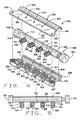
- Fig. 4 is an upside down, exploded view of another exemplary embodiment of a valve of the present invention
- Fig. 5 is a top plan view of the slide housing of the valve of Fig. 3
- Fig. 6 is a front plan view of the slide housing of Fig. 4
- Fig. 1 is a top perspective view of a cushion employing a cushion valve
- Fig. 2 is a bottom plan view of the cushion and cushion valve shown in Fig. 1
- Fig. 3 is a perspective view of the valve of the present invention attached to a peripheral edge of an inflatable cushiuon
- Fig. 4 is an upside down, exploded view of another exemplary embodiment of a valve of the present invention
- Fig. 7 is an exploded view of the slide housing and slide;
- Fig. 8 is a bottom plan view of one half of the valve casing of the valve of Fig. 3 ;
- Fig. 9 is a top plan view of the other half of the valve casing;
- Fig. 10 is an enlarged, partial cross-sectional view of the disassembled valve taken through the center of a connector nipple and connector seat, the connector nipple inserted in the air conduit and connector seat, prior to assembly of the casing;
- Fig. 11 is an enlarged, partial cross-sectional view of the assembled valve taken through the center of a connector nipple and connector seat, the connector nipple inserted in the air conduit and connector seat.
- the letter A designates one exemplary embodiment of a cellular cushion which is highly flexible and is designed for use on an underlying supporting surface, such as the seat of a wheelchair, the seat of a vehicle or the seat of a conventional chair.
- cushion A distributes the weight of its occupant generally uniformly over the entire area of the buttocks and thereby dissipates the pressures resulting from the supported weight of the ischia, that is, the bony prominence of the buttocks. It further has the capacity to position and stabilize the user.
- the valve assembly can also be employed with an air mattress or air mattress section or other similar devices that include inflatable zones.
- the cushion A includes a base 2 and air cells 4 that project upwardly from the base 2.
- the air cells 4 are molded as a conformal having a web 5 interconnecting the cells 4.
- the base is comprised of the web and a backing 3.
- Both the backing 3 and the air cells 4 preferably can be molded or otherwise formed from a highly flexible neoprene.
- the cells 4 and web 5 may be formed over a mandrel in a dipping operation as described in U.S. Patent No. 4,541,136 .
- the air cells 4 can be molded from a highly flexible neoprene and the base 2 can be vacuum formed of the web and a backing formed from polyurethane, for example, and appropriately attached to the conformal.
- the base 2 generally is rectangular and the cells 4 are arranged on it in longitudinal and transverse rows, with each cell occupying both a longitudinal and a transverse row.
- the present invention can be used with a cushion employing any preferred configuration of cells 4, that is, for example, cells having any number of fins or sides, cells having no fins, for example, cylindrical, cubical cells or rounded cells.
- the cells 4 are further arranged in zones, typically four zones r , s , t and u .
- the zones r and s lie side by side at the front of the cushion A and the zones t and u exist side by side at the rear of the cushion A.
- the right zones r and u are separated from the left zones s and t along a longitudinale axis x
- the front zones r and s are separated from the rear zones t and u along a transverse axis y . More or fewer zones and differing arrangements of those zones may be employed.
- the cells 4 of the zone r communicate with each other, so that all exist at the same general internal pressure irrespective of how far any individual cell is depressed.
- the cells 4 of the zone s are normally isolated from the cells of the remaining zones s , t and u.
- the cells 4 of the zone s are normally isolated as are the cells 4 of zones r , t and u and so forth.
- the cells 4 of each zone r , s , t and u collectively define a separate inflation zone or compartment.
- a fluid conduit 6 extends from zone t toward the front of the cushion.
- a fluid conduit 8 extends from zone u to the front of the cushion.
- Two shorter conduits 10 and 12 extend from zones s and r respectively toward the front of the cushion.
- the conduits 6, 8, 10 and 12 all terminate near an edge of the cushion and are in fluid communication with the cushion valve of the present invention, as will be explained in detail below.
- the various conduits can be formed in any appropriate manner without departing from the scope of the invention.
- the conduits can be formed integrally in the base 2 when the base is molded or vacuum formed.
- the illustrated embodiment is one acceptable configuration of conduits.
- the conduits can be formed in any acceptable manner that results in access to the conduits at one location on the periphery of the cushion so that valve of the present invention can be utilized.
- the conduits can be formed into the web 5 or can comprise separate tubing without departing from the scope of the invention.
- An air filling valve 14 is located at zone r that is opened and closed simply by turning its end. It will be appreciated, however, that the air fill valve can be located at any desirable and convenient location on the cushion.
- the conduits 6, 8, 10 and 12 are operatively connected to a valve 20.
- the valve 20 isolates the cells 4 of the several zones r , s , t and u. But when opened, it interconnects the zones r , s , t , and u , so that the interiors of all the cells 4 in all zones are in communication and, therefore, all exist at the same internal pressure.
- the air filling valve 14 enables air to be pumped into the cells 4 of the zone in which it is located and, when the valve 20 is open, the air inflates the cells 4 of all of the zones r , s , t and u . Use of only one air-filling valve 14 insures all of the cells 4 in the zones r , s , t , and u will be at the same initial pressure, even though the volume of air in the cells or zones may vary in use.
- valve 600 includes novel attachment and sealing features, which now will be explained in detail. As seen in Fig. 3 , valve 600 is attached to the peripheral edge E of a cushion that includes four air conduits 6, 8, 10 and 12 which are in fluid connection with the zones r , s , t and u , as previously explained. Valve 600 includes an outer casing 602 comprising two halves or sections 604 and 606.
- section 604 which generally is the top section when attached to a cushion as shown in Fig. 3 , has a forward segment 607 and a rear segment 608 that has a generally semi-circular cross section that defines a trough 610 that extends the length of the section.
- Forward section 607 has a generally greater material thickness than the rear segment, has a substantially flat outer surface 611 ( Fig. 3 ).
- the inside of segment 607 has a series of equally spaced nipple connector seats comprised of depressions 612, 614, 616 and 618 in the material thickness and, in the embodiment shown, having a semi-circular cross section which are perpendicular to trough 610.
- Nipple seat 612 has a pair of spaced apart raised detents 634 and 636 formed on the surface.
- nipple seat 614 includes raised detents 638, 640
- nipple groove 616 includes raised detents 642, 644 and nipple seat 618 has raised detents 646, 648.
- Casing half 606 has forward segment 650 which is substantially flat and rear segment 652 having a generally semi-circular cross section defining a trough 654.
- the overall shape of casing half 606 is complementary to that of casing half 604.
- the inside surface 655 of forward segment 650 has four pairs of spaced apart raised detents, 656, 658; 660, 662; 664, 666; and 668, 670.
- Forward segment 650 includes three equally spaced mounting holes 672, 674, 676 between the pairs of raised detents.
- Segment 650 includes wings 678 and 680 with mounting holes 682, 684, respectively formed therein.
- mounting holes 672, 674, 676, 682 and 684 of casing section 604 are positioned to be in alignment with 620, 622, 624, 630 and 632 of casing section 606 when the two halves of the casing are aligned.
- Troughs 610 and 654 cooperate to define a cavity 686 ( Fig. 10 ) that extends the length of the casing (excluding the wings) when the two halves are aligned.
- raised detents 656, 658; 660, 662; 664, 666; and 668, 670 of casing section 606 are positioned to be aligned across from the raise detents 634, 636; 638, 640; 642, 644; and 646, 648, respectively, of casing section 604 when the two casing sections are aligned in an assembled arrangement.
- Valve 600 includes a slide housing 686 that fits between the two halves of the casing.
- the slide housing 686 and internal slide 688 are shown in detail in Figs. 4, 5 and 7 .
- Slide housing 686 has a casing 690 comprising a substantially cylindrical wall 690 with a longitudinal inner bore 692.
- the cylindrical wall 690 is dimensioned to seat in cavity 686.
- Slide housing 686 includes a series of connector nipples 694, 696, 698, 700 evenly spaced along its length.
- Each connector nipple has an inner bore, as at 701, which is perpendicular to, and opens into, inner bore 692.
- the respective connector nipples in the embodiment illustrated, have a substantially semi-circular or D-shaped cross section.
- nipple connector 694, 696, 698, and 700 each has a pair of spaced apart circumferential retainer grooves 702 and 704, 706 and 708; 710 and 712, and 714 and 716, respectively, in external surface of the nipple connector.
- the nipple connectors are designed to seat in the connector seats 612, 614, 616 and 618.
- the pairs of detents 634, 636, 638, 640, 642, 644 and 646, 648 formed on the surface of the connector seats align with the pairs of grooves on the rounded side of the connector seat when the connector nipples are positioned in the connector seats.
- the retainer grooves on the flatter side of the connector nipples align with the detents 656, 658; 660, 662; 664, 666; and 668, 670 on the surface of the second casing section 606 when the valve is assembled.
- the nipple connectors 694, 696, 698, 700 are dimensioned to fit snugly inside the ends of the air conduits 6, 8, 10 and 12, as will be explained in greater detail below.
- Slide 688 is engaged in slide housing bore 692 so that it can move axially within the slide housing bore.
- Slide 688 is generally tubular in construction having a wall 689 and internal bore 720.
- O" ring seals 730, 732, 734, 736, 738, 740, 742, 744 and 746 are position on each side of the respective ports to make a fluid or airtight seal around the ports and create discrete air chambers C-1, C-2, C-3 and C-4. Air in the chamber can flow around the circumference of the slide and enter the associated port.
- the slide 688 is plugged at each end with plugs 748 and 750.
- Plugs 748 and 750 provide structure for the user to grasp or touch to manipulate the slide and operate as stops when the slide is moved axially within the casing bore.
- the air chambers around openings 722, 724, 726 and 728 are placed into and out of alignment with the nipple connectors 700, 698, 696 and 694, respectively, when the nipple connectors are attached to the air conduits, to open and close the valve and to allow air flow or block air flow among the cushion A inflation zones, as explained with reference to other exemplary embodiments above.
- the slide ports are aligned, and in registry with, the openings to the air conduits, it is not necessary that the two sets of openings be in perfect alignment.
- the air chambers C-1, C-2, C-3 and C-4 are in alignment with the openings.
- the air can flow around the slide within the air chamber and enter or exit through the port. This allows the slide valve to function even if the user inadvertently rotates the slide around its longitudinal axis, taking the two sets of openings out of registry.
- the outer casing, slide housing and slide can be cylindrical, ovoid, triangular, rectangular or any other shape in cross-section as long the slide can be manipulated from side-to-side to move the respective openings into and out of functional alignment.
- valve 600 provides for enhanced attachment to cushion A, as will now be explained.
- Figs. 3 , 10 and 11 it will be understood that one each of the nipple connectors is introduced into the open end of one of the air conduits.
- each conduit has a generally D-shaped cross section, raised on the top side and flat on the base side.
- nipple connector 694 is inserted into the end of air conduit 12. Once the connector nipples are positioned in an air conduit, the two halves 606, 608 of the valve casing are positioned on each side of the slide housing 686 in a clamshell arrangement with the slide housing body 690 seated in cavity 686.
- peripheral edge E of the cushion overlap peripheral edge E of the cushion.
- the two halves then are tightly fastened together with rivets R, or other appropriate fasteners such as screws or the like, through the opposed and aligned mounting holes 672, 674, 676, 682, 684 and 620, 622, 624, 630 and 632 and through holes punched in the peripheral edge of the cushion A.
- peripheral edge E and air conduit 12 are impinged between the casing halves, in particular, pinching the material between the retainer grooves 702, 704 and the opposed detents 646, 648 and 668, 670. This impinging arrangement exists along the length of the valve, including each air conduit, thereby tightly clamping the valve to the periphery of the cushion A to prevent the valve from pulling out of the cushion.
- adhesive or glue G can be introduced into the retainer grooves, as illustrated, grooves 702 and 704. Because a dollop of the adhesive is applied in the grooves, when the nipple connector is inserted into the open end of the conduit, the glue G generally stays in place in the grooves and is not mechanically pushed toward the body of the slide housing by the conduit wall, as can happen if adhesive is applied to a connector nipple having a smooth surface.
- the detents engage the retainer grooves and force the adhesive out of the retainer grooves, causing it to flow onto the surfaces along the length of the nipple connector and the air conduit, as shown in Fig. 10 , to provide for a better bond between the nipple connector and the air conduit.
- This process is duplicated with each nipple connector and air conduit. Consequently, the valve of the present invention provides for an enhanced mechanical attachment and adhesive attachment to the cushion.
- valve 600 as illustrated provides for two retainer grooves on each connector nipple and, correspondingly, two retainer detents on the inside surfaces of both the first casing section and second casing section, it will be understood that various aspects of the invention can be accomplished if the nipple connector had one or more than two retainer grooves. Correspondingly, the casing halves can have one retainer detent or more that two. It is within the scope of the invention if the nipple connector has more retainer grooves than the casing sections have detents. Valve 600 can be constructed with more than four connector nipples or fewer than four connector nipples if there are more or less air conduits on the inflatable cushion.
- valve 600 can have an appropriate detent structure associated with the slide or the slide housing to secure the slide in place.
- cushion A and the novel valve are designed for seat cushions, they may be expanded in use and, as previously discussed, configured differently in the arrangement of the zones or the number of zones. Further, the same inventive principles can be applied to inflatable mattress, auto, truck, bicycle or motorcycle seat cushions or any other type of air cushioned seating or resting surface. Consequently, the term "cushion" as used in the appended claims is intended to include any such seating apparatus, regardless of configuration or application. Moreover, the novel valve may be employed in any air inflated device, other than cushions, which is divided in to air chambers or zones.
Landscapes
- General Engineering & Computer Science (AREA)
- Engineering & Computer Science (AREA)
- Mechanical Engineering (AREA)
- Health & Medical Sciences (AREA)
- Veterinary Medicine (AREA)
- Life Sciences & Earth Sciences (AREA)
- Animal Behavior & Ethology (AREA)
- General Health & Medical Sciences (AREA)
- Public Health (AREA)
- Nursing (AREA)
- Mattresses And Other Support Structures For Chairs And Beds (AREA)
- Multiple-Way Valves (AREA)
- Check Valves (AREA)
- Sliding Valves (AREA)
- Bedding Items (AREA)
- Secondary Cells (AREA)
Abstract
Description
- This invention relates in general to inflatable mattresses and cushions and, more particularly, to an improved valve for use with an inflatable mattress or cushion having normally isolated zones to place the normally isolated zones in communication with each other or with the atmosphere in any desired arrangement of communication. The valve has improved attachment and sealing features.
- Those individuals who are confined to wheelchairs run the risk of tissue breakdown and the development of pressure sores, which are extremely dangerous and difficult to treat and cure. Typically, much of the individual's weight concentrates in the region of the ischia, that is, at the bony prominence of the buttocks, and unless frequent movement occurs, the flow of blood to the skin tissue in these regions decreases to the point that the tissue breaks down. Cushions that are especially designed for wheelchairs exist for reducing the concentration of weight in the region of the ischia, and these cushions generally seek to distribute the user's weight more uniformly over a larger area of the buttocks.
- Cellular cushions provide the most uniform distribution of weight and thus provide the greatest protection from the occurrence of pressure sores. These cushions have an array of closely spaced air cells that project upwardly from a common base. Within the base the air cells communicate with each other, and thus, all exist at the same internal pressure. Hence, each air cell exerts essentially the same restoring force against the buttocks, irrespective of the extent to which it is deflected.
U.S. Patent No. 4,541,136 shows a cellular cushion currently manufactured and sold by ROHO, Inc. of Belleville, Illinois, for use on wheelchairs. - In a sense the typical cellular cushion provides a highly displaceable surface that tends to float the user. While this reduces the incidence of pressure sores, it detracts from the stability one usually associates with a seating surface. Most of those confined to wheelchairs have little trouble adjusting to the decrease in stability, but for those who have skeletal deformities, particularly in the region of the pelvis and thighs, and for those who lack adequate strength in their muscles, lesser stability can be a source of anxiety. A variation of the cellular cushion addresses this problem with totally isolated zones and also with cells of varying height. By varying the volume of air between zones, for example, one can accommodate for skeletal deformities while still maintaining satisfactory protection against pressure sores.
U.S. Pat. No. 4,698,864 , owned by the assignee of the instant invention, shows zoned cellular cushion with cells of varying height. - Typically, a zoned cellular cushion has a separate filling stem and valve for each of its zones. The user simply opens the valve of each stem and introduces air into the zone for the stem, usually with a hand pump, and then releases the air from the zones until the desired posture is achieved. In a more sophisticated arrangement, a hose kit connects a single pump to a manifold, which in turn is connected to the several valves through separate hoses. Those hoses are fitted with separate hose clamps so that the air from the pump may be directed to the cells of the individual zones independently. Likewise, the air can be released from them independently, all by manipulating the clamps.
- The hoses of the hose kit lie externally of the cushion and may become entangled in the components of a wheelchair. Furthermore, by reason of their remote locations, the hose clamps are difficult to manipulate. Examples of zoned inflatable cushions that demonstrate significant advantages from zoning are provided in
U.S. Patent No. 5,163,196 andU.S. Patent No. 5,502,855 . The '196 patent describes a valve for a zoned inflatable cushion such that access to all of the zones is cut off simultaneously because the valve is in a flap which is part of the cushion base and all of the access channels run through the flap.U.S. Patent No. 5,502,855 utilizes a series of hoses to inflate the cushion and gathers the ends of the hoses in close proximity adjacent one edge of the cushion to prevent tangling. The cushion of the `855 patent also provides access to the cushion zones from beneath the cushion and provides access to each cell so as to be able to monitor from remote locations. - The present invention is an improvement on valves required by zoned cellular cushions. Heretofore, the zoned cushions employed integral channels which lead from the several zones and which are connected through an integral common manifold and associated valve. One such valve comprises a flap that is folded over to seal off the ends of the channels or opened to allow communication between the zones through a manifold contained within the flap. Through use it has been determined that these flap-type valves and other prior art zoned cushion valves suffer from some drawbacks. First, in the flap-type valve, the flap has to be manually folded closed and secured with a snap or the like. Often these types of apparatus are difficult for a disabled individual to manipulate. The flap can be awkwardly positioned under the cushion.
- A more urgent concern is that the flap valve possibly could leak or fail if the ends of the channels are not appropriately sealed. Continued use and normal wear over time may impair the effectiveness of the flap-type valve. Leaking through the valve could result in unwanted communication between the zones or, in the worst case, could result in loss of air from the cushion and a phenomenon known as "bottoming out" where the user's buttocks come to rest on an non-cushioned surface. If the user has no sensation or feeling in the buttocks, for example, the user could "bottom out" and not be aware.
- Newer valves designed to prevent leakage are the subject matter of
US 6,564,410 B2 (published June 06, 2002 ) andWO 02/065004 (published August 22, 2002 - The present invention provides a valve assembly (600) for use with an inflatable apparatus having a base and an array of upstanding fluid filled cells on one side of the base, the array of cells being divided into a plurality of inflation zones (r, s, t, u) each zone having a separate air conduit (6, 8, 10, 12) extending from the zone, comprising an outer casing (602) defining a slide housing seat; a slide housing (686) within the slide housing seat (610, 654), the slide housing having a longitudinal bore (692) and comprising least one connector (694, 696, 698, 700) having an inner bore (701) for fluid communication between an air conduit (6, 8, 10, 12) and the slide housing longitudinal bore (692); and a slide (688) within said slide housing bore (692), said slide comprising a wall (689) defining a longitudinal bore (720) and at least one opening (722, 724, 726, 728) through the slide wall (689) into said slide bore (720), wherein movement of the slide within the slide housing bore (692) to a first position places the at least one slide opening (722, 724, 726, 728) in fluid communication with the at least one connector (694, 696, 698, 700), thereby opening the valve, and movement of the slide within the slide housing bore (692) to a second position places the at least one slide opening (722, 724, 726, 728) out of fluid communication with the at least one connector (694, 696, 698, 700) thereby closing the valve, characterized in that the outer casing (602) comprises first and second sections (604, 606) which are attachable to the inflatable apparatus, said at least one connector (694, 696, 698, 700) has at least one retainer groove (702, 704, 706, 708, 710, 712, 714, 716) formed therein, and said first casing section (604) defines at least one connector seat (612, 614, 616,618) having at least one detent (634, 636, 638, 640, 642, 644, 646, 648) therein positioned to engage the at least one retainer groove (702, 704, 706, 708, 710, 712, 714, 716) when the casing is attached to the apparatus.
- The present invention also provides a method of attaching a valve to a cellular cushion comprising a flexible base having a peripheral edge, a plurality of flexible hollow air cells fixed to and projecting upwardly from the base, the cells being separated into independent pneumatic zones, and an air conduit operatively connected to each of said independent pneumatic zones and terminating adjacent the peripheral edge, characterized by introducing an adhesive into retainer grooves formed in an external surface of each of a plurality of conduit connectors on a valve slide housing; aligning one each of the connectors with an open end of one each of the cushion air conduits; inserting said connectors into the air conduits; positioning a first valve casing section on the peripheral edge of the cushion at a first side of the slide housing, said first valve casing section having a plurality of detents formed on an inner surface, each one of the detents positioned to align with a connector retainer groove; positioning a second valve casing section on the peripheral edge of the cushion at an opposite side of the slide housing, said second valve section having a plurality of detents formed on an inner surface, each one of the last said detents positioned to align a connector retainer groove; and securing the first valve casing section to the second valve casing section to impinge the peripheral edge of the cushion and the air conduits between the retainer grooves and the detents on the first and second valve casing sections and displace adhesive from the retainer grooves to form adhesive seals between the air conduits and the connectors.
- In a preferred embodiment each nipple connector has at least a pair of retainer grooves in the surface. Dents on each casing half engage the cushion edge and the retainer grooves to retain the nipple in the air conduits by spreading adhesive that was introduced into the grooves prior to inserting the connector nipple into the air conduit and also by physically impinging the cushion material and connector nipples between the two halves of the casing.
- The various aspects of the invention are achieved as set forth in the illustrative embodiments shown in the drawings, which form a part of the specification.
Fig. 1 is a top perspective view of a cushion employing a cushion valve;
Fig. 2 is a bottom plan view of the cushion and cushion valve shown inFig. 1 ;
Fig. 3 is a perspective view of the valve of the present invention attached to a peripheral edge of an inflatable cushiuon;
Fig. 4 is an upside down, exploded view of another exemplary embodiment of a valve of the present invention;
Fig. 5 is a top plan view of the slide housing of the valve ofFig. 3 ;
Fig. 6 is a front plan view of the slide housing ofFig. 4 ;
Fig. 7 is an exploded view of the slide housing and slide;
Fig. 8 is a bottom plan view of one half of the valve casing of the valve ofFig. 3 ;
Fig. 9 is a top plan view of the other half of the valve casing;
Fig. 10 is an enlarged, partial cross-sectional view of the disassembled valve taken through the center of a connector nipple and connector seat, the connector nipple inserted in the air conduit and connector seat, prior to assembly of the casing; and
Fig. 11 is an enlarged, partial cross-sectional view of the assembled valve taken through the center of a connector nipple and connector seat, the connector nipple inserted in the air conduit and connector seat. - Corresponding reference numerals refer to corresponding elements of the invention throughout the accompanying drawings.
- Referring now to the drawings (
Figs. 1-2 ), the letter A designates one exemplary embodiment of a cellular cushion which is highly flexible and is designed for use on an underlying supporting surface, such as the seat of a wheelchair, the seat of a vehicle or the seat of a conventional chair. Being cellular, cushion A distributes the weight of its occupant generally uniformly over the entire area of the buttocks and thereby dissipates the pressures resulting from the supported weight of the ischia, that is, the bony prominence of the buttocks. It further has the capacity to position and stabilize the user. It will be appreciated that although the present invention is described as employed on a cushion, the valve assembly can also be employed with an air mattress or air mattress section or other similar devices that include inflatable zones. - The cushion A includes a
base 2 andair cells 4 that project upwardly from thebase 2. Generally theair cells 4 are molded as a conformal having aweb 5 interconnecting thecells 4. The base is comprised of the web and abacking 3. Both thebacking 3 and theair cells 4 preferably can be molded or otherwise formed from a highly flexible neoprene. Thecells 4 andweb 5 may be formed over a mandrel in a dipping operation as described inU.S. Patent No. 4,541,136 . On the other hand, theair cells 4 can be molded from a highly flexible neoprene and thebase 2 can be vacuum formed of the web and a backing formed from polyurethane, for example, and appropriately attached to the conformal. - The
base 2 generally is rectangular and thecells 4 are arranged on it in longitudinal and transverse rows, with each cell occupying both a longitudinal and a transverse row. It will be appreciated that although the illustrated embodiment provides for individual cells each having a configuration consisting of four fins F, the configuration of the individual cells is incidental to the invention. The present invention can be used with a cushion employing any preferred configuration ofcells 4, that is, for example, cells having any number of fins or sides, cells having no fins, for example, cylindrical, cubical cells or rounded cells. - The
cells 4 are further arranged in zones, typically four zones r, s, t and u. The zones r and s lie side by side at the front of the cushion A and the zones t and u exist side by side at the rear of the cushion A. The right zones r and u are separated from the left zones s and t along a longitudinale axis x, whereas the front zones r and s are separated from the rear zones t and u along a transverse axis y. More or fewer zones and differing arrangements of those zones may be employed. - Within the
base 2 thecells 4 of the zone r communicate with each other, so that all exist at the same general internal pressure irrespective of how far any individual cell is depressed. The same holds true with regard to thecells 4 of the zone s, thecells 4 of the zone t, and thecells 4 of the zone u. In other words, thecells 4 of zone r are normally isolated from the cells of the remaining zones s, t and u. Likewise, thecells 4 of the zone s are normally isolated as are thecells 4 of zones r, t and u and so forth. Thus, thecells 4 of each zone r, s, t and u collectively define a separate inflation zone or compartment. - A
fluid conduit 6 extends from zone t toward the front of the cushion. Likewise afluid conduit 8 extends from zone u to the front of the cushion. Twoshorter conduits conduits base 2 when the base is molded or vacuum formed. - The illustrated embodiment is one acceptable configuration of conduits. The conduits can be formed in any acceptable manner that results in access to the conduits at one location on the periphery of the cushion so that valve of the present invention can be utilized. By way of example, the conduits can be formed into the
web 5 or can comprise separate tubing without departing from the scope of the invention. Anair filling valve 14 is located at zone r that is opened and closed simply by turning its end. It will be appreciated, however, that the air fill valve can be located at any desirable and convenient location on the cushion. - The
conduits valve 20. When closed, thevalve 20 isolates thecells 4 of the several zones r,s,t and u. But when opened, it interconnects the zones r, s, t, and u, so that the interiors of all thecells 4 in all zones are in communication and, therefore, all exist at the same internal pressure. Theair filling valve 14 enables air to be pumped into thecells 4 of the zone in which it is located and, when thevalve 20 is open, the air inflates thecells 4 of all of the zones r, s, t and u. Use of only one air-fillingvalve 14 insures all of thecells 4 in the zones r, s, t, and u will be at the same initial pressure, even though the volume of air in the cells or zones may vary in use. - The novel valve of the present invention for a zoned cellular cushion is indicated generally by
reference numeral 600 inFigs. 3-11 .Valve 600 includes novel attachment and sealing features, which now will be explained in detail. As seen inFig. 3 ,valve 600 is attached to the peripheral edge E of a cushion that includes fourair conduits Valve 600 includes anouter casing 602 comprising two halves orsections - Referring to
Figs. 4 and8 ,section 604, which generally is the top section when attached to a cushion as shown inFig. 3 , has aforward segment 607 and arear segment 608 that has a generally semi-circular cross section that defines atrough 610 that extends the length of the section.Forward section 607 has a generally greater material thickness than the rear segment, has a substantially flat outer surface 611 (Fig. 3 ). The inside ofsegment 607 has a series of equally spaced nipple connector seats comprised ofdepressions trough 610. In between the nipple seats are series of three equally spaced mountingholes segment 607 is awing 626 and at the opposite end iswing 628. Mountingholes wings Nipple seat 612 has a pair of spaced apart raiseddetents nipple seat 614 includes raiseddetents nipple groove 616 includes raiseddetents nipple seat 618 has raiseddetents -
Casing half 606 has forwardsegment 650 which is substantially flat andrear segment 652 having a generally semi-circular cross section defining atrough 654. The overall shape ofcasing half 606 is complementary to that ofcasing half 604. The inside surface 655 offorward segment 650 has four pairs of spaced apart raised detents, 656, 658; 660, 662; 664, 666; and 668, 670.Forward segment 650 includes three equally spaced mountingholes Segment 650 includeswings holes holes casing section 604 are positioned to be in alignment with 620, 622, 624, 630 and 632 ofcasing section 606 when the two halves of the casing are aligned. -
Troughs Fig. 10 ) that extends the length of the casing (excluding the wings) when the two halves are aligned. Also, raiseddetents casing section 606 are positioned to be aligned across from theraise detents casing section 604 when the two casing sections are aligned in an assembled arrangement. -
Valve 600 includes aslide housing 686 that fits between the two halves of the casing. Theslide housing 686 andinternal slide 688 are shown in detail inFigs. 4, 5 and7 .Slide housing 686 has acasing 690 comprising a substantiallycylindrical wall 690 with a longitudinalinner bore 692. Thecylindrical wall 690 is dimensioned to seat incavity 686.Slide housing 686 includes a series ofconnector nipples inner bore 692. The respective connector nipples, in the embodiment illustrated, have a substantially semi-circular or D-shaped cross section. As best seen inFig. 5 ,nipple connector circumferential retainer grooves - The nipple connectors are designed to seat in the connector seats 612, 614, 616 and 618. The pairs of
detents detents second casing section 606 when the valve is assembled. Thenipple connectors air conduits -
Internal slide 688 is engaged in slide housing bore 692 so that it can move axially within the slide housing bore.Slide 688 is generally tubular in construction having awall 689 andinternal bore 720. There is a series of linearly aligned, spaced apart openings orports bore 720. O" ring seals 730, 732, 734, 736, 738, 740, 742, 744 and 746 are position on each side of the respective ports to make a fluid or airtight seal around the ports and create discrete air chambers C-1, C-2, C-3 and C-4. Air in the chamber can flow around the circumference of the slide and enter the associated port. Theslide 688 is plugged at each end withplugs flat washer 751 between the threaded plug and the end of the slide to facilitate sealing the end of the slide with the plugs.Plugs openings nipple connectors - It will be appreciated that, although in the illustrated embodiments, for purposes of clarity, the slide ports are aligned, and in registry with, the openings to the air conduits, it is not necessary that the two sets of openings be in perfect alignment. For the slide to function in an open position, for example, all that is necessary is for the air chambers C-1, C-2, C-3 and C-4 to be in alignment with the openings. As explained above, the air can flow around the slide within the air chamber and enter or exit through the port. This allows the slide valve to function even if the user inadvertently rotates the slide around its longitudinal axis, taking the two sets of openings out of registry. Thus, when reference is made to the slide ports and the openings to the air conduits being in alignment or registry, this generally is defined as the air chambers around the slide ports being appropriately positioned with regard to the openings to the air conduits so as to allow fluid communication through the slide ports and the air conduits. Hence, it is not necessary that the two sets of openings be in perfect alignment or registry, but only requires functional alignment, that is, an alignment that allows the fluid flow function between the conduit opening and the associated slide port.
- The outer casing, slide housing and slide can be cylindrical, ovoid, triangular, rectangular or any other shape in cross-section as long the slide can be manipulated from side-to-side to move the respective openings into and out of functional alignment.
- The structure of
valve 600 provides for enhanced attachment to cushion A, as will now be explained. Referring toFigs. 3 ,10 and 11 , it will be understood that one each of the nipple connectors is introduced into the open end of one of the air conduits. In the embodiment shown, each conduit has a generally D-shaped cross section, raised on the top side and flat on the base side. By way of example, referring toFigs. 10 and 11 ,nipple connector 694 is inserted into the end ofair conduit 12. Once the connector nipples are positioned in an air conduit, the twohalves slide housing 686 in a clamshell arrangement with theslide housing body 690 seated incavity 686. The relatively flat forward sections of the casing halves, 607 and 650 overlap peripheral edge E of the cushion. The two halves then are tightly fastened together with rivets R, or other appropriate fasteners such as screws or the like, through the opposed and aligned mountingholes air conduit 12 are impinged between the casing halves, in particular, pinching the material between theretainer grooves opposed detents - Furthermore, as shown in
Fig. 10 , prior to insertion of a nipple connector into the conduit, adhesive or glue G can be introduced into the retainer grooves, as illustrated,grooves Fig. 10 , to provide for a better bond between the nipple connector and the air conduit. This process, of course, is duplicated with each nipple connector and air conduit. Consequently, the valve of the present invention provides for an enhanced mechanical attachment and adhesive attachment to the cushion. - Although
valve 600 as illustrated provides for two retainer grooves on each connector nipple and, correspondingly, two retainer detents on the inside surfaces of both the first casing section and second casing section, it will be understood that various aspects of the invention can be accomplished if the nipple connector had one or more than two retainer grooves. Correspondingly, the casing halves can have one retainer detent or more that two. It is within the scope of the invention if the nipple connector has more retainer grooves than the casing sections have detents.Valve 600 can be constructed with more than four connector nipples or fewer than four connector nipples if there are more or less air conduits on the inflatable cushion. - As explained above with reference to other exemplary embodiments, an inflation apparatus also could be attached to
valve 600 to allow inflation of all four zones of the cushion as described in detail above. As with the other embodiments,valve 600 can have an appropriate detent structure associated with the slide or the slide housing to secure the slide in place. - While cushion A and the novel valve are designed for seat cushions, they may be expanded in use and, as previously discussed, configured differently in the arrangement of the zones or the number of zones. Further, the same inventive principles can be applied to inflatable mattress, auto, truck, bicycle or motorcycle seat cushions or any other type of air cushioned seating or resting surface. Consequently, the term "cushion" as used in the appended claims is intended to include any such seating apparatus, regardless of configuration or application. Moreover, the novel valve may be employed in any air inflated device, other than cushions, which is divided in to air chambers or zones.
- The foregoing description and the accompanying drawings are intended to be illustrative of the best mode of working the invention presently known to the inventors and should not be construed in a limiting sense.
Claims (7)
- A valve assembly (600) for use with an inflatable apparatus having a base and an array of upstanding fluid filled cells on one side of the base, the array of cells being divided into a plurality of inflation zones (r, s, t, u) each zone having a separate air conduit (6, 8, 10, 12) extending from the zone, comprising an outer casing (602) defining a slide housing seat; a slide housing (686) within the slide housing seat (610, 654), the slide housing having a longitudinal bore (692) and comprising least one connector (694, 696, 698, 700) having an inner bore (701) for fluid communication between an air conduit (6, 8, 10, 12) and the slide housing longitudinal bore (692); and a slide (688) within said slide housing bore (692), said slide comprising a wall (689) defining a longitudinal bore (720) and at least one opening (722, 724, 726, 728) through the slide wall (689) into said slide bore (720), wherein movement of the slide within the slide housing bore (692) to a first position places the at least one slide opening (722, 724, 726, 728) in fluid communication with the at least one connector (694, 696, 698, 700), thereby opening the valve, and movement of the slide within the slide housing bore (692) to a second position places the at least one slide opening (722, 724, 726, 728) out of fluid communication with the at least one connector (694, 696, 698, 700) thereby closing the valve, characterized in that the outer casing (602) comprises first and second sections (604, 606) which are attachable to the inflatable apparatus, said at least one connector (694, 696, 698, 700) has at least one retainer groove (702, 704, 706, 708, 710, 712, 714, 716) formed therein, and said first casing section (604) defines at least one connector seat (612, 614, 616,618) having at least one detent (634, 636, 638, 640, 642, 644, 646, 648) therein positioned to engage the at least one retainer groove (702, 704, 706, 708, 710, 712, 714, 716) when the casing is attached to the apparatus.
- The valve assembly of claim 1, characterized in that a second casing section (606) further comprises at least one retainer detent (656, 658, 660, 662, 64, 666, 668, 670) positioned to engage the at least one retainer groove in the connector when the casing is attached to the apparatus.
- The valve assembly of claim 1, characterized in that said slide housing (686() further comprises a plurality of connectors (694, 696, 698, 700) for fluid connection between the air conduits (6, 8, 10, 12) and the slide housing bore (692)
- The valve assembly of claim 3, characterized in that said first casing section (664) has a plurality connectors seats (612, 614, 616, 618) which are perpendicular to said slide housing seat (610)
- The valve assembly of claim 1, characterized in that each of said plurality of connectors has a substantially semi-circular cross section.
- The valve assembly of claim 1, characterized in that the first and second casing sections are adjusted to impinge a cushion base peripheral edge and the air conduits between the casing sections when the valve is attached to a cushion.
- A method of attaching a valve to a cellular cushion comprising a flexible base having a peripheral edge, a plurality of flexible hollow air cells fixed to and projecting upwardly from the base, the cells being separated into independent pneumatic zones, and an air conduit operatively connected to each of said independent pneumatic zones and terminating adjacent the peripheral edge, characterized by introducing an adhesive into retainer grooves formed in an external surface of each of a plurality of conduit connectors on a valve slide housing; aligning one each of the connectors with an open end of one each of the cushion air conduits; inserting said connectors into the air conduits; positioning a first valve casing section on the peripheral edge of the cushion at a first side of the slide housing, said first valve casing section having a plurality of detents formed on an inner surface, each one of the detents positioned to align with a connector retainer groove; positioning a second valve casing section on the peripheral edge of the cushion at an opposite side of the slide housing, said second valve section having a plurality of detents formed on an inner surface, each one of the last said detents positioned to align a connector retainer groove; and securing the first valve casing section to the second valve casing section to impinge the peripheral edge of the cushion and the air conduits between the retainer grooves and the detents on the first and second valve casing sections and displace adhesive from the retainer grooves to form adhesive seals between the air conduits and the connectors.
Applications Claiming Priority (3)
| Application Number | Priority Date | Filing Date | Title |
|---|---|---|---|
| US255277 | 2002-09-26 | ||
| US10/255,277 US6687936B2 (en) | 2001-01-18 | 2002-09-26 | Valve for zoned cellular cushion |
| PCT/US2003/009406 WO2004028307A1 (en) | 2002-09-26 | 2003-03-25 | Valve for zoned cellular cushion |
Publications (3)
| Publication Number | Publication Date |
|---|---|
| EP1542567A1 EP1542567A1 (en) | 2005-06-22 |
| EP1542567A4 EP1542567A4 (en) | 2005-11-02 |
| EP1542567B1 true EP1542567B1 (en) | 2008-12-03 |
Family
ID=32041744
Family Applications (1)
| Application Number | Title | Priority Date | Filing Date |
|---|---|---|---|
| EP03718078A Expired - Lifetime EP1542567B1 (en) | 2002-09-26 | 2003-03-25 | Valve for zoned cellular cushion |
Country Status (18)
| Country | Link |
|---|---|
| US (1) | US6687936B2 (en) |
| EP (1) | EP1542567B1 (en) |
| JP (1) | JP4314195B2 (en) |
| KR (1) | KR100710129B1 (en) |
| AT (1) | ATE415841T1 (en) |
| AU (1) | AU2003222092A1 (en) |
| BR (1) | BR0306490B1 (en) |
| CA (1) | CA2468313C (en) |
| DE (1) | DE60325075D1 (en) |
| DK (1) | DK1542567T3 (en) |
| ES (1) | ES2319274T3 (en) |
| HR (1) | HRP20040460A2 (en) |
| MX (1) | MXPA04004944A (en) |
| NO (1) | NO328712B1 (en) |
| PT (1) | PT1542567E (en) |
| RU (1) | RU2298393C2 (en) |
| WO (1) | WO2004028307A1 (en) |
| YU (1) | YU45904A (en) |
Families Citing this family (53)
| Publication number | Priority date | Publication date | Assignee | Title |
|---|---|---|---|---|
| US10357114B2 (en) * | 1999-04-20 | 2019-07-23 | Wcw, Inc. | Inflatable cushioning device with manifold system |
| US6269505B1 (en) | 1999-04-20 | 2001-08-07 | M.P.L. Ltd. | Inflatable cushioning device with manifold system |
| WO2002058615A2 (en) * | 2001-01-25 | 2002-08-01 | Hill-Rom Services, Inc. | Hydraulic actuator apparatus for a surgical table |
| US7434282B2 (en) * | 2003-05-29 | 2008-10-14 | Star Cushion Products, Inc. | Cellular cushions and methods of fabricating |
| US20050121953A1 (en) * | 2003-12-03 | 2005-06-09 | Sprouse Anthony E.Ii | Motorcycle seat |
| US20070235036A1 (en) * | 2004-04-30 | 2007-10-11 | Bobey John A | Patient support |
| US7557718B2 (en) * | 2004-04-30 | 2009-07-07 | Hill-Rom Services, Inc. | Lack of patient movement monitor and method |
| US7883478B2 (en) | 2004-04-30 | 2011-02-08 | Hill-Rom Services, Inc. | Patient support having real time pressure control |
| US7469436B2 (en) * | 2004-04-30 | 2008-12-30 | Hill-Rom Services, Inc. | Pressure relief surface |
| DE602005027786D1 (en) * | 2004-10-06 | 2011-06-16 | Hill Rom Services Inc | Device for improving an air flow under a patient |
| AU2006269277B2 (en) * | 2005-07-08 | 2012-02-16 | Hill-Rom, Inc. | Patient support |
| JP5231222B2 (en) | 2005-07-08 | 2013-07-10 | ヒル−ロム サービシーズ,インコーポレイティド | Patient support control unit |
| AU2006268287B2 (en) | 2005-07-08 | 2012-03-08 | Hill-Rom Services, Inc. | Pressure control for a hospital bed |
| US7350251B2 (en) * | 2005-07-12 | 2008-04-01 | Kevin Gerard Fraser | Cellular cushion |
| US7681265B2 (en) * | 2005-07-12 | 2010-03-23 | Star Cushion Products, Inc. | Cellular cushion |
| US8745788B2 (en) | 2005-07-26 | 2014-06-10 | Hill-Rom Services. Inc. | System and method for controlling an air mattress |
| US7536739B2 (en) * | 2005-08-10 | 2009-05-26 | Kreg Medical, Inc. | Therapeutic mattress |
| US20070056112A1 (en) * | 2005-09-09 | 2007-03-15 | Graebe Robert H | Zoned cellular cushion with fail safe inflation zones |
| US20070056114A1 (en) * | 2005-09-09 | 2007-03-15 | Corey Lewison | Multi-zone coil construction airbed |
| US7604292B1 (en) | 2005-11-03 | 2009-10-20 | Reading Randall C | Vehicle seat with dynamic cushion and lumbar support |
| US9119753B2 (en) | 2008-06-27 | 2015-09-01 | Kreg Medical, Inc. | Bed with modified foot deck |
| WO2010028029A2 (en) * | 2008-09-08 | 2010-03-11 | Roho, Inc. | Inflatable cushion valve and attachment apparatus |
| US20100175196A1 (en) * | 2008-12-17 | 2010-07-15 | Patrick Lafleche | Patient support |
| EP2531159B1 (en) | 2010-02-05 | 2018-01-24 | Stryker Corporation | Patient/invalid support |
| US8584286B2 (en) | 2010-04-27 | 2013-11-19 | Ec Service Inc. | Systems and methods for providing a self deflating cushion |
| US8832883B2 (en) * | 2010-06-12 | 2014-09-16 | American Home Health Care, Inc. | Patient support systems |
| CN102450885A (en) * | 2010-10-23 | 2012-05-16 | 李武钢 | Adjustable seat cushion capable of adapting to figure and sitting posture |
| CA2858608C (en) * | 2010-12-09 | 2020-03-10 | Akonni Biosystems | Sample analysis system |
| EP2731567B1 (en) | 2011-07-13 | 2016-12-14 | Stryker Corporation | Patient/invalid handling support |
| US20130031722A1 (en) * | 2011-08-01 | 2013-02-07 | Tin Cheung Wong | Air-conditioning bed |
| US8973186B2 (en) | 2011-12-08 | 2015-03-10 | Hill-Rom Services, Inc. | Optimization of the operation of a patient-support apparatus based on patient response |
| CN103565624A (en) * | 2012-07-18 | 2014-02-12 | 上海创始实业(集团)有限公司 | Pressure sore prevention seat cushion |
| US9468307B2 (en) | 2012-09-05 | 2016-10-18 | Stryker Corporation | Inflatable mattress and control methods |
| US9801767B2 (en) * | 2013-03-14 | 2017-10-31 | Kap Medical, Inc. | Patient support apparatus and method |
| US9782312B2 (en) | 2013-09-05 | 2017-10-10 | Stryker Corporation | Patient support |
| US9839300B2 (en) | 2014-01-29 | 2017-12-12 | Roho, Inc. | Reduced outflow inflation valve |
| US10179077B2 (en) | 2014-04-18 | 2019-01-15 | Kreg Medical, Inc. | Patient support with stand-up and sit features |
| TWI645119B (en) * | 2014-08-25 | 2018-12-21 | 雃博股份有限公司 | Gas connecting device and gas exporting method thereof |
| KR200484671Y1 (en) | 2015-12-15 | 2017-10-16 | 주식회사 씰테크 | Air Cell Cushion |
| EP3410896A4 (en) * | 2016-02-04 | 2019-09-04 | Roho, Inc. | VALVE ASSEMBLY FOR INFLATION OF CUSHIONS |
| JP6706112B2 (en) * | 2016-03-24 | 2020-06-03 | 住友理工株式会社 | Fluid cell type mattress and its control method |
| US10309540B2 (en) * | 2016-10-03 | 2019-06-04 | John M. Eise | Valves for controlling fluid passage |
| GB201720097D0 (en) * | 2017-12-01 | 2018-01-17 | Anders Julian | Inflation valve for multi celled inflatable |
| US11540964B2 (en) | 2018-02-27 | 2023-01-03 | Hill-Rom Services, Inc. | Patient support surface control, end of life indication, and x-ray cassette sleeve |
| US10850655B2 (en) * | 2018-08-28 | 2020-12-01 | The Boeing Company | Shape adapting system and method for a cushion assembly |
| US20210227991A1 (en) * | 2020-01-24 | 2021-07-29 | Patientech Llc | Controllable beds |
| CN111544275A (en) * | 2020-05-08 | 2020-08-18 | 广东粤华医疗器械厂有限公司 | Self-adaptive locking cushion capable of regulating pressure |
| CN113455340A (en) * | 2021-07-02 | 2021-10-01 | 广西壮族自治区自然资源生态修复中心 | Farmland irrigation early warning device for comprehensive land improvement and application |
| US11801175B2 (en) | 2022-01-07 | 2023-10-31 | Permobil, Inc. | Multi-position airflow control assembly for an air cushion |
| US11739854B2 (en) | 2022-01-07 | 2023-08-29 | Permobil, Inc. | Valve assembly for an air cushion |
| US20240343174A1 (en) * | 2023-04-17 | 2024-10-17 | Lear Corporation | Valve assembly |
| US20250108945A1 (en) * | 2023-09-29 | 2025-04-03 | Wcw, Inc. | Body support and method of packing a body support |
| US20250280968A1 (en) * | 2024-03-08 | 2025-09-11 | Permobil, Inc. | Multiport airflow control assembly for an air cushion |
Family Cites Families (84)
| Publication number | Priority date | Publication date | Assignee | Title |
|---|---|---|---|---|
| US805237A (en) | 1905-02-18 | 1905-11-21 | Willard T Sears | Self-cleaning air-screen valve. |
| US1397220A (en) | 1918-12-16 | 1921-11-15 | Lawrence S Lord | Faucet |
| US1468072A (en) | 1921-04-14 | 1923-09-18 | Ogle Hubert Millas | Comfort cushion |
| US1746953A (en) | 1928-02-23 | 1930-02-11 | Mary L Mccollum | Sanitary pad for nursery chairs |
| US1821719A (en) | 1928-08-10 | 1931-09-01 | Messier George Louis Rene Jean | Brake controlling device |
| US1775856A (en) | 1929-05-24 | 1930-09-16 | Albert B Hauser | Four-way valve |
| US1935119A (en) | 1930-07-21 | 1933-11-14 | Heald Machine Co | Fluid pressure reversing valve mechanism |
| US1970803A (en) | 1932-10-03 | 1934-08-21 | Johnson John Herbert | Method of making an inflatable rubber structure |
| US2078402A (en) | 1935-09-20 | 1937-04-27 | Mcdonough James Moore | Releasable choke |
| US2136510A (en) | 1936-09-23 | 1938-11-15 | Gustav B Jensen | Automobile seat inflation device |
| US2182982A (en) | 1937-10-30 | 1939-12-12 | Evans John | Four-way valve mechanism |
| US2260437A (en) | 1939-06-02 | 1941-10-28 | Laura A Chambers | Seat cushion structure |
| US2434641A (en) | 1946-02-20 | 1948-01-20 | Henry L Burns | Resilient seat cushion |
| US2575764A (en) | 1947-04-10 | 1951-11-20 | Hans G Morner | Air-filled upholstery and method of manufacture |
| US2645450A (en) | 1948-11-26 | 1953-07-14 | C B Hunt & Son Inc | Fluid valve means |
| US2731652A (en) | 1951-06-01 | 1956-01-24 | Edward P Bishop | Air mattress |
| US2906492A (en) | 1951-06-01 | 1959-09-29 | Baker Oil Tools Inc | Valves |
| US2838099A (en) | 1953-08-04 | 1958-06-10 | Ernest H Warner | Back cushion for automobiles or the like |
| US2858851A (en) | 1954-09-16 | 1958-11-04 | James W F Holl | Push-pull valve |
| US3044491A (en) | 1958-07-29 | 1962-07-17 | Texas Instruments Inc | Multiport switching valve |
| US3000399A (en) | 1958-09-12 | 1961-09-19 | Clayton J Brukner | Lock proof two position spool valve |
| US3112956A (en) | 1961-08-30 | 1963-12-03 | Schick Melvin Edward | Inflatable seat and back rest |
| US3192540A (en) | 1962-01-22 | 1965-07-06 | Richard E Swank | Adjustable pneumatic support |
| US3200846A (en) | 1962-02-15 | 1965-08-17 | Clyde S Beck | Fluid control device |
| GB969367A (en) | 1962-03-05 | 1964-09-09 | George Ingram | Improvements in inflatable mattresses, pillows and cushions |
| US3192541A (en) | 1962-03-19 | 1965-07-06 | Boyd S Moore | Contourable pneumatic cushions |
| US3215163A (en) | 1964-06-23 | 1965-11-02 | Republic Mfg Company | Two-position, four-way pilot operated valve |
| US3308851A (en) | 1964-07-10 | 1967-03-14 | Robertshaw Controls Co | Pneumatic controlled selector valve |
| US3385113A (en) | 1965-11-03 | 1968-05-28 | Prec Sampling Corp | Multiport valves |
| US3462778A (en) | 1966-02-25 | 1969-08-26 | Gaymar Ind Inc | Inflatable mattress and pressure system |
| NL6717616A (en) | 1967-09-15 | 1969-03-18 | ||
| US3828821A (en) | 1968-10-08 | 1974-08-13 | J Dotter | Pressure regulator faucet slide valve |
| US3605145A (en) | 1968-12-05 | 1971-09-20 | Robert H Graebe | Body support |
| DE1951476A1 (en) | 1969-10-13 | 1971-07-08 | Meyer Geb Urbank | Lying mat |
| GB1285456A (en) | 1969-11-28 | 1972-08-16 | Colin William Dee | Air cushions or like apparatus for supporting an item, such as the human body |
| US3678959A (en) | 1970-07-30 | 1972-07-25 | Richard B Liposky | Hand operable selector valve |
| US3707168A (en) | 1970-09-30 | 1972-12-26 | Uni Mist | Rotary spool valve |
| US3806084A (en) | 1971-06-21 | 1974-04-23 | Scm Corp | Improved valve dispensing apparatus |
| US3763891A (en) | 1972-01-13 | 1973-10-09 | M Stiltner | Control valve |
| US3893481A (en) | 1973-03-13 | 1975-07-08 | Watts Ltd H & D | Mixer taps or valves |
| US4005236A (en) | 1973-05-16 | 1977-01-25 | Graebe Robert H | Expandable multicelled cushioning structure |
| US3870450A (en) | 1973-05-16 | 1975-03-11 | Robert H Graebe | Multicelled structure apparatus for making same |
| DE2348124C3 (en) | 1973-09-25 | 1978-06-15 | Gerard Kingersheim Burgin (Frankreich) | Seat and / or backrest cushions for a chair or armchair |
| SE406151B (en) | 1975-06-09 | 1979-01-29 | Petersson New Products Investa | INFLATABLE REST PILLOW |
| US3984886A (en) | 1975-08-20 | 1976-10-12 | Keeton J Herbert | Fluid-filled cushioning assemblies |
| US4182374A (en) | 1976-09-25 | 1980-01-08 | Moschoula Spanides | Control device for regulating the flow between a spout and a shower and capable of controlling the rate of flow from each independently of the hot and cold faucet handles |
| US4186734A (en) | 1978-03-22 | 1980-02-05 | Stratton John M | Inflatable seat unit |
| US4219532A (en) | 1978-10-10 | 1980-08-26 | Borden, Inc. | Foaming device |
| US4231399A (en) | 1979-02-05 | 1980-11-04 | Pauliukonis Richard S | Momentary contact reversing diverter |
| US4267611A (en) | 1979-03-08 | 1981-05-19 | Arnold Agulnick | Inflatable massaging and cooling mattress |
| US4279044A (en) | 1979-11-16 | 1981-07-21 | Owen Douglas | Fluid support system for a medical patient |
| US4370769A (en) | 1980-09-19 | 1983-02-01 | Herzig Ralph B | Cushion utilizing air and liquid |
| US4422194A (en) | 1981-08-24 | 1983-12-27 | Connecticut Artcraft Corp. | Fluid filled body supporting device |
| SU1106925A1 (en) * | 1982-08-03 | 1984-08-07 | Byrykin Vladimir P | Distributor |
| US4541136A (en) | 1983-09-01 | 1985-09-17 | Graebe Robert H | Multicell cushion |
| US4662012A (en) | 1983-12-07 | 1987-05-05 | Torbet Philip A | Bed utilizing an air mattress |
| DE3345291C2 (en) | 1983-12-14 | 1987-04-16 | Klaus Dieter Dr.med. 8345 Birnbach Hellwig | Inflatable seat cushion |
| US4698864A (en) | 1985-11-25 | 1987-10-13 | Graebe Robert H | Cellular cushion |
| US4690171A (en) | 1986-06-05 | 1987-09-01 | Johnston Charles F | Valve assembly for a sphygmomanometer |
| SU1588386A1 (en) * | 1987-07-02 | 1990-08-30 | В.И. Матвеев | Mattress |
| US4852195A (en) | 1987-10-16 | 1989-08-01 | Schulman David A | Fluid pressurized cushion |
| NO174452C (en) | 1988-01-18 | 1994-05-11 | Finn Risung | Individually adjustable cushion system |
| US4864671A (en) | 1988-03-28 | 1989-09-12 | Decubitus, Inc. | Controllably inflatable cushion |
| US5052068A (en) | 1989-11-14 | 1991-10-01 | Graebe Robert H | Contoured seat cushion |
| US5444881A (en) | 1989-12-04 | 1995-08-29 | Supracor Systems, Inc. | Anatomical support apparatus |
| US5090076A (en) | 1990-10-31 | 1992-02-25 | Hans Guldager | Multiple cell inflation element |
| US5502855A (en) | 1990-11-01 | 1996-04-02 | Graebe; Robert H. | Zoned cellular cushion |
| US5163196A (en) | 1990-11-01 | 1992-11-17 | Roho, Inc. | Zoned cellular cushion with flexible flaps containing inflating manifold |
| US5111544A (en) | 1991-07-01 | 1992-05-12 | Graebe Robert H | Cover with elastic top and frictional bottom for a cushion |
| RU2005452C1 (en) * | 1992-01-29 | 1994-01-15 | Чернышов Алексей Петрович | Method for controlling anti-bedsore action on areas of patient's body and device for prevention of bedsores |
| US5373595A (en) | 1993-03-12 | 1994-12-20 | Irvin Industries Canada Ltd. | Air support device |
| US5564143A (en) | 1995-03-09 | 1996-10-15 | Dielectrics Industries | Check valve for fluid bladders |
| US5678265A (en) | 1996-01-11 | 1997-10-21 | Meyer; Kenneth G. | Inflatable cushion |
| US5765594A (en) | 1996-04-02 | 1998-06-16 | Danfoss A/S | Hydraulic control valve |
| US5839140A (en) | 1996-04-03 | 1998-11-24 | Geomarine Systems, Inc. | Inflatable wheelchair cushion and methods of manufacturing and use |
| US5689845A (en) | 1996-04-17 | 1997-11-25 | Roho, Inc. | Expansible air cell cushion |
| US5772182A (en) | 1996-04-17 | 1998-06-30 | United Technologies Corporation | Fuel flow control valve |
| GB9616769D0 (en) | 1996-08-09 | 1996-09-25 | Pegasus Airwave Ltd | Connector |
| US6122785A (en) | 1997-07-01 | 2000-09-26 | Airsports Technology, L.L.C. | Air pad |
| NO305462B1 (en) | 1997-09-12 | 1999-06-07 | Bre Cushion As | Pressure relief cushion and method for making pressure relief cushion |
| US6058538A (en) | 1998-10-07 | 2000-05-09 | Huntleigh Technology, Plc | Patient support |
| US6321401B1 (en) | 2000-01-07 | 2001-11-27 | T. L. Clark, Inc. | Infection control mat |
| WO2002065004A1 (en) | 2001-01-18 | 2002-08-22 | Roho, Inc. | Valve for zoned cellular cushion |
| US6557587B1 (en) * | 2001-11-02 | 2003-05-06 | Ching-Ping Chiu | Change-over valve |
-
2002
- 2002-09-26 US US10/255,277 patent/US6687936B2/en not_active Expired - Lifetime
-
2003
- 2003-03-25 RU RU2004116075A patent/RU2298393C2/en not_active IP Right Cessation
- 2003-03-25 JP JP2004539773A patent/JP4314195B2/en not_active Expired - Lifetime
- 2003-03-25 HR HR20040460A patent/HRP20040460A2/en not_active Application Discontinuation
- 2003-03-25 BR BRPI0306490-5B1A patent/BR0306490B1/en active IP Right Grant
- 2003-03-25 EP EP03718078A patent/EP1542567B1/en not_active Expired - Lifetime
- 2003-03-25 WO PCT/US2003/009406 patent/WO2004028307A1/en not_active Ceased
- 2003-03-25 CA CA002468313A patent/CA2468313C/en not_active Expired - Lifetime
- 2003-03-25 MX MXPA04004944A patent/MXPA04004944A/en active IP Right Grant
- 2003-03-25 AT AT03718078T patent/ATE415841T1/en active
- 2003-03-25 YU YUP45904 patent/YU45904A/en unknown
- 2003-03-25 KR KR1020047007965A patent/KR100710129B1/en not_active Expired - Lifetime
- 2003-03-25 AU AU2003222092A patent/AU2003222092A1/en not_active Abandoned
- 2003-03-25 DE DE60325075T patent/DE60325075D1/en not_active Expired - Lifetime
- 2003-03-25 ES ES03718078T patent/ES2319274T3/en not_active Expired - Lifetime
- 2003-03-25 PT PT03718078T patent/PT1542567E/en unknown
- 2003-03-25 DK DK03718078T patent/DK1542567T3/en active
-
2004
- 2004-06-16 NO NO20042526A patent/NO328712B1/en not_active IP Right Cessation
Also Published As
| Publication number | Publication date |
|---|---|
| KR100710129B1 (en) | 2007-04-20 |
| NO328712B1 (en) | 2010-05-03 |
| JP2006500153A (en) | 2006-01-05 |
| ATE415841T1 (en) | 2008-12-15 |
| DK1542567T3 (en) | 2009-03-23 |
| RU2004116075A (en) | 2005-03-10 |
| US6687936B2 (en) | 2004-02-10 |
| PT1542567E (en) | 2009-03-06 |
| NO20042526L (en) | 2005-05-09 |
| BR0306490B1 (en) | 2013-11-12 |
| RU2298393C2 (en) | 2007-05-10 |
| BR0306490A (en) | 2004-10-13 |
| HK1077174A1 (en) | 2006-02-10 |
| JP4314195B2 (en) | 2009-08-12 |
| CA2468313C (en) | 2008-11-25 |
| HRP20040460A2 (en) | 2005-04-30 |
| WO2004028307A9 (en) | 2004-09-02 |
| KR20050047035A (en) | 2005-05-19 |
| AU2003222092A8 (en) | 2004-04-19 |
| ES2319274T3 (en) | 2009-05-06 |
| YU45904A (en) | 2006-05-25 |
| US20030192125A1 (en) | 2003-10-16 |
| MXPA04004944A (en) | 2005-04-08 |
| EP1542567A1 (en) | 2005-06-22 |
| AU2003222092A1 (en) | 2004-04-19 |
| DE60325075D1 (en) | 2009-01-15 |
| WO2004028307A1 (en) | 2004-04-08 |
| EP1542567A4 (en) | 2005-11-02 |
| CA2468313A1 (en) | 2004-04-08 |
Similar Documents
| Publication | Publication Date | Title |
|---|---|---|
| CA2468313C (en) | Valve for zoned cellular cushion | |
| EP1352189B1 (en) | Valve for zoned cellular cushion | |
| US8739338B2 (en) | Inflatable cushion valve and attachment apparatus | |
| WO1997046148A1 (en) | Improved wheelchair cushion | |
| US20070056112A1 (en) | Zoned cellular cushion with fail safe inflation zones | |
| JP3706388B2 (en) | Banded cell type cushion | |
| US12178767B2 (en) | Multi-position airflow control assembly for an air cushion | |
| HK1077174B (en) | Valve for zoned cellular cushion |
Legal Events
| Date | Code | Title | Description |
|---|---|---|---|
| PUAI | Public reference made under article 153(3) epc to a published international application that has entered the european phase |
Free format text: ORIGINAL CODE: 0009012 |
|
| 17P | Request for examination filed |
Effective date: 20040621 |
|
| AK | Designated contracting states |
Kind code of ref document: A1 Designated state(s): AT BE BG CH CY CZ DE DK EE ES FI FR GB GR HU IE IT LI LU MC NL PT RO SE SI SK TR |
|
| AX | Request for extension of the european patent |
Extension state: AL LT LV MK |
|
| A4 | Supplementary search report drawn up and despatched |
Effective date: 20050916 |
|
| RAX | Requested extension states of the european patent have changed |
Extension state: MK Payment date: 20040621 |
|
| REG | Reference to a national code |
Ref country code: HK Ref legal event code: DE Ref document number: 1077174 Country of ref document: HK |
|
| GRAP | Despatch of communication of intention to grant a patent |
Free format text: ORIGINAL CODE: EPIDOSNIGR1 |
|
| GRAS | Grant fee paid |
Free format text: ORIGINAL CODE: EPIDOSNIGR3 |
|
| GRAS | Grant fee paid |
Free format text: ORIGINAL CODE: EPIDOSNIGR3 |
|
| GRAA | (expected) grant |
Free format text: ORIGINAL CODE: 0009210 |
|
| AK | Designated contracting states |
Kind code of ref document: B1 Designated state(s): AT BE BG CH CY CZ DE DK EE ES FI FR GB GR HU IE IT LI LU MC NL PT RO SE SI SK TR |
|
| AX | Request for extension of the european patent |
Extension state: MK |
|
| REG | Reference to a national code |
Ref country code: GB Ref legal event code: FG4D |
|
| REG | Reference to a national code |
Ref country code: CH Ref legal event code: EP |
|
| REG | Reference to a national code |
Ref country code: IE Ref legal event code: FG4D |
|
| REF | Corresponds to: |
Ref document number: 60325075 Country of ref document: DE Date of ref document: 20090115 Kind code of ref document: P |
|
| REG | Reference to a national code |
Ref country code: PT Ref legal event code: SC4A Free format text: AVAILABILITY OF NATIONAL TRANSLATION Effective date: 20090226 |
|
| REG | Reference to a national code |
Ref country code: SE Ref legal event code: TRGR |
|
| REG | Reference to a national code |
Ref country code: DK Ref legal event code: T3 |
|
| REG | Reference to a national code |
Ref country code: CH Ref legal event code: NV Representative=s name: BRAUNPAT BRAUN EDER AG |
|
| REG | Reference to a national code |
Ref country code: ES Ref legal event code: FG2A Ref document number: 2319274 Country of ref document: ES Kind code of ref document: T3 |
|
| PG25 | Lapsed in a contracting state [announced via postgrant information from national office to epo] |
Ref country code: SI Free format text: LAPSE BECAUSE OF FAILURE TO SUBMIT A TRANSLATION OF THE DESCRIPTION OR TO PAY THE FEE WITHIN THE PRESCRIBED TIME-LIMIT Effective date: 20081203 |
|
| REG | Reference to a national code |
Ref country code: HK Ref legal event code: GR Ref document number: 1077174 Country of ref document: HK |
|
| PG25 | Lapsed in a contracting state [announced via postgrant information from national office to epo] |
Ref country code: EE Free format text: LAPSE BECAUSE OF FAILURE TO SUBMIT A TRANSLATION OF THE DESCRIPTION OR TO PAY THE FEE WITHIN THE PRESCRIBED TIME-LIMIT Effective date: 20081203 Ref country code: RO Free format text: LAPSE BECAUSE OF FAILURE TO SUBMIT A TRANSLATION OF THE DESCRIPTION OR TO PAY THE FEE WITHIN THE PRESCRIBED TIME-LIMIT Effective date: 20081203 Ref country code: BG Free format text: LAPSE BECAUSE OF FAILURE TO SUBMIT A TRANSLATION OF THE DESCRIPTION OR TO PAY THE FEE WITHIN THE PRESCRIBED TIME-LIMIT Effective date: 20090303 |
|
| PG25 | Lapsed in a contracting state [announced via postgrant information from national office to epo] |
Ref country code: SK Free format text: LAPSE BECAUSE OF FAILURE TO SUBMIT A TRANSLATION OF THE DESCRIPTION OR TO PAY THE FEE WITHIN THE PRESCRIBED TIME-LIMIT Effective date: 20081203 |
|
| PLBE | No opposition filed within time limit |
Free format text: ORIGINAL CODE: 0009261 |
|
| STAA | Information on the status of an ep patent application or granted ep patent |
Free format text: STATUS: NO OPPOSITION FILED WITHIN TIME LIMIT |
|
| PG25 | Lapsed in a contracting state [announced via postgrant information from national office to epo] |
Ref country code: MC Free format text: LAPSE BECAUSE OF NON-PAYMENT OF DUE FEES Effective date: 20090331 |
|
| 26N | No opposition filed |
Effective date: 20090904 |
|
| PG25 | Lapsed in a contracting state [announced via postgrant information from national office to epo] |
Ref country code: GR Free format text: LAPSE BECAUSE OF FAILURE TO SUBMIT A TRANSLATION OF THE DESCRIPTION OR TO PAY THE FEE WITHIN THE PRESCRIBED TIME-LIMIT Effective date: 20090304 |
|
| PG25 | Lapsed in a contracting state [announced via postgrant information from national office to epo] |
Ref country code: LU Free format text: LAPSE BECAUSE OF NON-PAYMENT OF DUE FEES Effective date: 20090325 |
|
| PG25 | Lapsed in a contracting state [announced via postgrant information from national office to epo] |
Ref country code: HU Free format text: LAPSE BECAUSE OF FAILURE TO SUBMIT A TRANSLATION OF THE DESCRIPTION OR TO PAY THE FEE WITHIN THE PRESCRIBED TIME-LIMIT Effective date: 20090604 |
|
| PG25 | Lapsed in a contracting state [announced via postgrant information from national office to epo] |
Ref country code: TR Free format text: LAPSE BECAUSE OF FAILURE TO SUBMIT A TRANSLATION OF THE DESCRIPTION OR TO PAY THE FEE WITHIN THE PRESCRIBED TIME-LIMIT Effective date: 20081203 |
|
| PG25 | Lapsed in a contracting state [announced via postgrant information from national office to epo] |
Ref country code: CY Free format text: LAPSE BECAUSE OF FAILURE TO SUBMIT A TRANSLATION OF THE DESCRIPTION OR TO PAY THE FEE WITHIN THE PRESCRIBED TIME-LIMIT Effective date: 20081203 |
|
| REG | Reference to a national code |
Ref country code: FR Ref legal event code: PLFP Year of fee payment: 14 |
|
| REG | Reference to a national code |
Ref country code: FR Ref legal event code: PLFP Year of fee payment: 15 |
|
| REG | Reference to a national code |
Ref country code: FR Ref legal event code: PLFP Year of fee payment: 16 |
|
| REG | Reference to a national code |
Ref country code: CH Ref legal event code: PCAR Free format text: NEW ADDRESS: HOLEESTRASSE 87, 4054 BASEL (CH) |
|
| PGFP | Annual fee paid to national office [announced via postgrant information from national office to epo] |
Ref country code: PT Payment date: 20200303 Year of fee payment: 18 Ref country code: AT Payment date: 20200304 Year of fee payment: 18 |
|
| PGFP | Annual fee paid to national office [announced via postgrant information from national office to epo] |
Ref country code: CZ Payment date: 20200310 Year of fee payment: 18 |
|
| PG25 | Lapsed in a contracting state [announced via postgrant information from national office to epo] |
Ref country code: CZ Free format text: LAPSE BECAUSE OF NON-PAYMENT OF DUE FEES Effective date: 20210325 |
|
| REG | Reference to a national code |
Ref country code: AT Ref legal event code: MM01 Ref document number: 415841 Country of ref document: AT Kind code of ref document: T Effective date: 20210325 |
|
| PG25 | Lapsed in a contracting state [announced via postgrant information from national office to epo] |
Ref country code: PT Free format text: LAPSE BECAUSE OF NON-PAYMENT OF DUE FEES Effective date: 20210927 |
|
| PG25 | Lapsed in a contracting state [announced via postgrant information from national office to epo] |
Ref country code: AT Free format text: LAPSE BECAUSE OF NON-PAYMENT OF DUE FEES Effective date: 20210325 |
|
| PGFP | Annual fee paid to national office [announced via postgrant information from national office to epo] |
Ref country code: IE Payment date: 20220325 Year of fee payment: 20 Ref country code: GB Payment date: 20220331 Year of fee payment: 20 Ref country code: DK Payment date: 20220317 Year of fee payment: 20 |
|
| PGFP | Annual fee paid to national office [announced via postgrant information from national office to epo] |
Ref country code: SE Payment date: 20220331 Year of fee payment: 20 Ref country code: NL Payment date: 20220323 Year of fee payment: 20 Ref country code: IT Payment date: 20220317 Year of fee payment: 20 Ref country code: FR Payment date: 20220325 Year of fee payment: 20 Ref country code: BE Payment date: 20220322 Year of fee payment: 20 |
|
| PGFP | Annual fee paid to national office [announced via postgrant information from national office to epo] |
Ref country code: ES Payment date: 20220421 Year of fee payment: 20 Ref country code: DE Payment date: 20220422 Year of fee payment: 20 |
|
| PGFP | Annual fee paid to national office [announced via postgrant information from national office to epo] |
Ref country code: FI Payment date: 20220421 Year of fee payment: 20 Ref country code: CH Payment date: 20220425 Year of fee payment: 20 |
|
| REG | Reference to a national code |
Ref country code: DE Ref legal event code: R071 Ref document number: 60325075 Country of ref document: DE |
|
| REG | Reference to a national code |
Ref country code: DK Ref legal event code: EUP Expiry date: 20230325 |
|
| REG | Reference to a national code |
Ref country code: NL Ref legal event code: MK Effective date: 20230324 |
|
| REG | Reference to a national code |
Ref country code: CH Ref legal event code: PL |
|
| REG | Reference to a national code |
Ref country code: BE Ref legal event code: MK Effective date: 20230325 |
|
| REG | Reference to a national code |
Ref country code: GB Ref legal event code: PE20 Expiry date: 20230324 |
|
| REG | Reference to a national code |
Ref country code: IE Ref legal event code: MK9A |
|
| REG | Reference to a national code |
Ref country code: ES Ref legal event code: FD2A Effective date: 20230428 |
|
| REG | Reference to a national code |
Ref country code: SE Ref legal event code: EUG |
|
| PG25 | Lapsed in a contracting state [announced via postgrant information from national office to epo] |
Ref country code: GB Free format text: LAPSE BECAUSE OF EXPIRATION OF PROTECTION Effective date: 20230324 |
|
| PG25 | Lapsed in a contracting state [announced via postgrant information from national office to epo] |
Ref country code: IE Free format text: LAPSE BECAUSE OF EXPIRATION OF PROTECTION Effective date: 20230325 Ref country code: ES Free format text: LAPSE BECAUSE OF EXPIRATION OF PROTECTION Effective date: 20230326 |