EP1542483A1 - Non-instantaneous hard handover control device and method - Google Patents
Non-instantaneous hard handover control device and method Download PDFInfo
- Publication number
- EP1542483A1 EP1542483A1 EP03792788A EP03792788A EP1542483A1 EP 1542483 A1 EP1542483 A1 EP 1542483A1 EP 03792788 A EP03792788 A EP 03792788A EP 03792788 A EP03792788 A EP 03792788A EP 1542483 A1 EP1542483 A1 EP 1542483A1
- Authority
- EP
- European Patent Office
- Prior art keywords
- information
- block
- resource
- cfn
- hho
- Prior art date
- Legal status (The legal status is an assumption and is not a legal conclusion. Google has not performed a legal analysis and makes no representation as to the accuracy of the status listed.)
- Withdrawn
Links
Images



Classifications
-
- H—ELECTRICITY
- H04—ELECTRIC COMMUNICATION TECHNIQUE
- H04W—WIRELESS COMMUNICATION NETWORKS
- H04W36/00—Hand-off or reselection arrangements
- H04W36/06—Reselecting a communication resource in the serving access point
Definitions
- the present invention relates to a non-instantaneous-disruption hard handover control device and method. More specifically, the present invention relates to a non-instantaneous-disruption hard handover control device and method, which are provided for a radio base station performing communication based on the CDMA (Code Division Multiple Access) technique, and perform drive-out control in the maintenance functions.
- CDMA Code Division Multiple Access
- a radio base station uses handover control that finds a new baseband resource (destination baseband resource) capable of allowing a call communicating in a baseband resource to autonomously continue the communication and thus allows the call to continue the communication by using this new resource.
- a new baseband resource destination baseband resource
- non-instantaneous-disruption hard handover control hereinafter referred to as non-instantaneous-disruption HHO
- Node-B radio base station
- 3GPP 3rd Generation Partnership Project
- FIG. 5 shows a non-instantaneous-disruption HHO sequence between a radio network controller (hereinafter referred to as an RNC) and a Node-B.
- FIG. 6 shows details of a radio link reconfiguration commit message sent from the RNC to the Node-B.
- the non-instantaneous-disruption HHO sequence in FIG. 5 occurs when the Node-B establishes a new radio link. At this time, it is assumed that a radio synchronization link configuration procedure is completed normally.
- the Node-B changes the radio link using a connection frame number (hereinafter referred to as a CFN) that arrives next.
- the CFN is contained in the radio link reconfiguration commit message from the RNC.
- the radio link handover using the CFN completes the non-instantaneous-disruption HHO.
- FIG. 7 is a block diagram showing the configuration of a conventional mobile communication system using the CDMA technique.
- FIG. 8 is a block diagram showing the configuration of the baseband signal block 706 in FIG. 7.
- the RNC 711 first establishes a radio link with a call-process/maintenance-process monitoring block 709 in the Node-B 703 via a wired transmission path 710.
- the radio link information is temporarily stored in the call-process/maintenance-process monitoring block 709 in the Node-B 703, and is then transferred to a search block 802a, a rake block 803a, and a codec block 804a (FIG. 8) in a baseband resource A 801a of the baseband signal block 706.
- An upstream signal from a mobile station 701 is input to an RX unit of a TX/RX AMP unit 704 in the Node-B 703 via a radio transmission path 702 and is A/D converted in an A/D & D/A conversion block 705.
- the converted signal is transferred to a baseband resource A 801a in the baseband signal block 706 via the upstream signal line 805.
- the baseband resource A 801a allows the search block 802a to perform multi-path detection and path tracking.
- the baseband resource A 801a then allows the rake block 803a to perform channel estimation, SIR detection, and RAKE combination.
- the baseband resource A 801a then allows the codec block 804a to perform a decode process (error correction process) for the RAKE-combined upstream signal and perform downstream transmission power control.
- the decoded upstream signal is transferred to an ATM cell composition block 707 for ATM cell conversion.
- a transmission I/F black 708 band-limits the ATM cell for each signal.
- the signal is then transmitted to the RNC 711 via the wired transmission path 710.
- a downstream signal from the RNC 711 is input to the transmission path I/F block 708 via the wired transmission path 710.
- the downstream signal is transferred to the ATM cell composition block 707 for ATM cell conversion.
- the downstream signal is then input to the baseband resource A 801a in the baseband signal block 706 via the downstream signal line 806.
- the baseband resource A 801a allows the codec block 804a to perform encoding processes (CRC generation process and error correction process) and upstream transmission power control for the downstream signal.
- the encoded downstream signal is D/A converted in the A/D & D/A conversion block 705.
- the downstream signal is transferred to the TX section of the TX/RX AMP unit 704 and then is transmitted to the mobile station 701 via the radio transmission path 702.
- the above-described processings are likewise performed in another baseband resource B 801b (search block 802b, rake block 803b, codec block 804b) disposed in the baseband signal block 706.
- the call-process/maintenance-process monitoring block 709 manages call processings and maintenance processings in the Node-B 703.
- the following describes processings for the non-instantaneous-disruption HHO performed by the Node-B 703 according to notification from the RNC 711.
- the Node-B 703 performs the non-instantaneous-disruption HHO for a call communicating in the baseband resource A 801a in the baseband signal block 706.
- the RNC 711 establishes a new radio link with the call-process/maintenance-process monitoring block 709 via the wired transmission path 710.
- the call-process/maintenance-process monitoring block 709 is then notified of the CFN as non-instantaneous-disruption HHO timing via the wired transmission path 710.
- the new radio link configuration and the CFN information are temporarily stored in the call-process/maintenance-process monitoring block 709 and are transferred to the search block 802a, the rake block 803a, and the codec block 804a in the baseband resource A 801a in the baseband signal block 706.
- the search block 802a, the rake block 803a, and the codec block 804a store therein the notified new radio link information and the CFN. These blocks switch the signal processings between upstream line signals and downstream line signals so as to perform processings based on the radio link information before the configuration until the CFN-1 timing is notified and to perform processings based on the new radio link information after the CFN timing is notified.
- the CFN which functions as non-instantaneous-disruption HHO timing, it is performed to compare the upstream CFNs used in the search block 802a, the rake block 803a, and the codec block 804a for upstream line signals with the downstream CFN used in the codec block 804a for downstream line signals.
- the search block 802a calculates an upstream CFN (regularly updated every 10 ms per radio frame) from the reference frame timing for multi-path detection. The search block 802a compares the calculated upstream CFN with the notified CFN. The rake block 803a calculates an upstream CFN (regularly updated every 10 ms per radio frame) to be used as the reference frame timing for RAKE combination. The rake block 803a compares the calculated upstream CFN with the notified CFN.
- the codec block 804a calculates an upstream CFN (regularly updated every 10 ms per radio frame) to be used as the reference frame for RAKE-combined data transferred from the rake block 803a during the decoding process.
- the codec block 804a compares the calculated upstream CFN with the notified CFN.
- These blocks each calculates and stores upstream CFN calculation timing. As a result, an information transfer delay can be limited to an allowable range. Thus, the upstream line signal can be switched without an instantaneous disruption.
- the codec block 804a calculates: CFN information concomitant with the downstream signal converted into the ATM cells in the ATM cell composition block 707; and the downstream CFN (regularly updated every 10 ms per radio frame) to be used as the reference frame during the encoding processes.
- the codec block 804a compares the calculated upstream CFN with the notified CFN. If there is no downstream line signal converted into ATM cells, the codec block 804a switches the downstream line signals based on the CFN to be used as the reference frame for the autonomous code process.
- the codec block 804a calculates and stores the downstream CFN calculation timing. Since no information transfer is performed, downstream line signals can be switched without an instantaneous disruption.
- the non-instantaneous-disruption HHO process uses the baseband resource A 801a before the HHO occurring.
- the resource stores therein the information needed before the handover timing such as acquired path information in the search block 802a and transmission-power control information in the codec block 804a. That is, the non-instantaneous-disruption HHO can be easily implemented so long as the search block 802a, the rake block 803a, and the codec block 804a respectively keep track of the CFN occurring as the handover timing.
- the Node-B 703 finds a new destination baseband resource capable of continued communication for a call communicating in the source baseband resource and allows the call to communicate using the new resource. That hard handover control corresponds to the drive-out control, one of the maintenance functions of a radio base station.
- the Node-B 703 autonomously performs the drive-out control, a then-communicating call requires hard handover without a instantaneous disruption.
- General procedures are specified for each Node-B 703 and may allow a situation where the instantaneous disruption is inevitable.
- the drive-out control is also expected to reliably implement the non-instantaneous-disruption HHO without affecting a communicating call.
- the present invention provides, in a first aspect thereof, a non-instantaneous-disruption hard handover (HHO) control device, disposed in a radio base station using a code-division-multiple-access (CDMA) technique, for switching a call from a source baseband resource to a destination baseband resource, the HHO control device including a CFN message generation block (110), provided in a call-processing/maintenance processing block, for generating a connection frame number (CFN) which specifies a handover timing.
- CDMA code-division-multiple-access
- the present invention also provides, in a second aspect thereof, a method for handover from a source baseband resource to a destination baseband resource without an instantaneous disruption in a radio communication system using a CDMA technique, the method including the step of generating a CFN message including a connection frame number (CFN) specifying a handover timing in a radio base station.
- a CFN message including a connection frame number (CFN) specifying a handover timing in a radio base station.
- CFN connection frame number
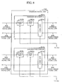
- FIG. 1 shows a mobile communication system using a CDMA technique, according to the embodiment of the present invention.
- the mobile communication system includes a mobile station 101, a Node-B 103, and an RNC 112.
- the mobile station 101 and the Node-B 103 are connected to each other via a radio transmission path 102.
- the RNC 112 and the Node-B 103 are connected to each other via a wired transmission path 111.
- the Node-B 103 includes a TX/RX AMP unit 104, an A/D & D/A conversion unit (block) 105, a baseband signal unit (block) 106, an ATM cell composition unit (block) 107, a transmission path I/F unit (block) 108, and a call-process/maintenance-process monitoring unit (block) 109.
- the call-process/maintenance-process monitoring block 109 includes therein a CFN generation unit (block) 110.
- FIG. 2 shows the configuration of the baseband signal block 106 in the present embodiment.
- the baseband signal block 106 includes a baseband resource A 201a and a baseband resource B 201b that can operate independently of each other.
- the baseband resource A 201a and the baseband resource B 201b transmit or receive data from the outside via an upstream signal line 206, a downstream signal line 207, and the like.
- the baseband resource A 201a and the baseband resource B 201b each includes a search unit (block) 202a or 202b, a rake unit (block) 203a or 203b, a codec unit (block) 204a or 204b, and an HHO-information write-in/read-in unit (device) 205a or 205b.
- the handover control finds a new destination baseband resource capable of continued communication for a call communicating in the baseband resource and provides hard handover control to the call for performing communication using the new resource.
- the CFN generation block 110 For the drive-out control, the CFN generation block 110 generates a CFN to be used as handover timing for the drive-out control, information as to the source baseband resource, and information as to the destination baseband resource.
- the CFN generation block 110 transfers the generated CFN message to: a search block 202a (source-resource search block 202a), a rake block 203a (source-resource rake block 203a), a codec block 204a (source-resource codec block 204a), and an HHO-information write-in/read-in unit 205a (source-resource HHO-information write-in/read-in unit 205a) in the source baseband resource A 201a of the baseband signal block 106; and a search block 202b (destination-resource search block 202b), a rake block 203b (destination-resource rake block 203b), a codec block 204b (destination-resource codec block 204b), and an HHO-information write-in/read-in unit 205b (destination-resource HHO-information write-in/read-in unit 205b) in the baseband
- the source-resource search block 202a transfers acquired path information to the source-resource HHO-information write-in/read-in unit 205a.
- the source-resource codec block 204a transfers radio-frame-synchronization identification information and transmission-power control information to the source-resource HHO-information write-in/read-in unit 205a.
- the source-resource HHO-information write-in/read-in unit 205a transfers these pieces of information (information messages) to the destination-resource HHO-information write-in/read-in unit 205b.
- the destination-resource HHO-information write-in/read-in unit 205b reads the transferred radio information.
- the destination-resource HHO-information write-in/read-in unit 205b transfers the acquired path information.
- the destination-resource HHO-information write-in/read-in unit 205b transfers the radio-frame-synchronization identification information and the transmission-power control information to the destination-resource codec block 204b.
- the baseband signal block 106 has two baseband resources A and B.
- the baseband signal block 106 may have a plurality of baseband resources C, D, and so on and each of the other blocks in the baseband block may have similar configuration.
- FIG. 3 shows a sequence flow for radio signal processings in the drive-out control according to the present embodiment, which are performed in: an AID & D/A conversion block 3A; a call-process/maintenance-process monitoring block 3B; a CFN generation block 3C; a search block 3D1 (source-resource search block 3D1), a rake block 3D2 (source-resource rake block 3D2), a codec block 3D3 (source-resource codec block 3D3), and an HHO-information write-in/read-in unit 3D4 (source-resource HHO-information write-in/read-in unit 3D4) in a source baseband resource A 201a; and a search block 3E1 (destination-resource search block 3E1), a rake block 3E2 (destination-resource rake block 3E2), a codec block 3E3 (destination-resource codec block 3E3)
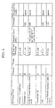
- FIG. 4 shows a CFN generation message in the CFN generation block 3C and a radio information message in the HHO-information write-in/read-in units 3D4 and 3E4.
- the radio information message includes radio-frame-synchronization identification information, transmission-power control information, and acquired path information.
- the call-process/maintenance-process monitoring block 3B Prior to providing the drive-out control for a communicating call in FIG. 3, the call-process/maintenance-process monitoring block 3B, in process 301, issues an instruction to notify generation of a CFN capable of non-instantaneous-disruption HHO to the CFN generation block 3C. After receiving the instruction for CFN generation notification, the CFN generation block 3C generates a CFN in process 302. The CFN generation block 3C notifies the generated CFN to the call-process/maintenance-process monitoring block 3B based on the CFN generation message generated by the CFN generation block shown in FIG. 4.
- the CFN generation message contains source baseband resource information, destination baseband resource information, and a CFN specifying the handover timing.
- the source baseband resource information and the destination baseband resource information are needed for the drive-out control and are used for source resource nodes and destination resource nodes.
- the call-process/maintenance-process monitoring block 3B receives the CFN generation message.
- the call-process/maintenance-process monitoring block 3B transfers the CFN generation message to: a source-resource search block 3D1, a source-resource rake block 3D2, a source-resource codec block 3D3, and a source-resource HHO-information write-in/read-in unit 3D4 in the source baseband resource A 201a; and a destination-resource search block 3E1, a destination-resource rake block 3E2, a destination-resource codec block 3E3, and a destination-resource HHO-information write-in/read-in unit 3E4 in the baseband resource B 201b to become a destination resource.
- the source-resource codec block 3D3 in the source baseband resource A 201a receives the CFN generation message from the call-process/maintenance-process monitoring block 3B.
- the source-resource codec block 3D3 notifies the radio-frame-synchronization identification information and the transmission-power control information at the present moment to the source-resource HHO-information write-in/read-in unit 3D4.
- the source-resource search block 3D1 in the source baseband resource A 201a receives the CFN generation message from the call-process/maintenance-process monitoring block 3B. In process 305, the source-resource search block 3D1 notifies the acquired path information at the present moment to the source-resource HHO-information write-in/read-in unit 3D4.
- the source-resource HHO-information write-in/read-in unit 3D4 in the source baseband resource A 201a references the information about the source baseband resource in the CFN generation message transferred via the call-process/maintenance-process monitoring block 3B to identify the to-be destination baseband resource B 201b.
- the source-resource HHO-information write-in/read-in unit 3D4 so as not to exceed the CFN occurring as the handover timing, transfers the acquired path information from the source-resource search block 3D1 and the radio-frame-synchronization identification information and the transmission-power control information from the source-resource codec block 3D3 to the destination-resource HHO-information write-in/read-in unit 3E4 in the destination baseband resource B 201b. That is, the source-resource HHO-information write-in/read-in unit 3D4 transfers the information message (radio information) shown in FIG. 4.
- the above-described processings complete the information transfer from the source baseband resource A 201a to the destination baseband resource B 201b.
- the source-resource search block 3D1, the source-resource rake block 3D2, and the source-resource codec block 3D3 in the source baseband resource A 201a perform signal processings until the timing CFN-1 immediately before the handover timing.
- Process 308 relates to upstream line signals at timing (time) CFN-2 (CNF-2 indicates a CFN which precedes the current CFN by two).
- CNF-2 indicates a CFN which precedes the current CFN by two.
- the source-resource search block 3D1 uses the converted upstream signal to calculate an upstream CFN according to the reference frame timing for performing the multi-path detection.
- the source-resource search block 3D1 compares the calculated CFN with the CFN to be used as the notified handover timing and then performs the multi-path detection and the path tracking.
- the source-resource rake block 3D2 also calculates an upstream CFN to be used as the reference frame timing for RAKE combination.
- the source-resource rake block 3D2 compares the calculated CFN with the CFN to be used as the handover timing and then performs the channel estimation, the SIR detection, and the RAKE combination.
- the source-resource codec block 3D3 also calculates an upstream CFN to be used as the reference frame for RAKE-combined data transferred from the source-resource rake block 3D2.
- the source-resource codec block 3D3 compares the calculated CFN with the CFN to be used as the handover timing, and then performs the decode process (error correction process) for the RAKE-combined upstream signal.
- the source-resource codec block 3D3 transfers the decoded upstream signal to the ATM cell composition block 3F.
- Process 309 relates to downstream line signals at the CFN-2 timing (time).
- the source-resource codec block 3D3 uses a downstream signal converted into ATM cells in the ATM cell composition block 3F and calculates CFN information concomitant with the downstream signal converted into the ATM cells and a downstream CFN to be used as the reference frame for the encoding process.
- the source-resource codec block 3D3 compares the calculated CFN with the CFN to be used as the handover timing.
- the source-resource codec block 3D3 compares the CFN which is to become the reference frame for the autonomous code process with the CFN to be used as the handover timing, and then performs the encoding processes (CRC generation process and error correction process) and the upstream transmission power control for the downstream signal.
- the source-resource codec block 3D3 transfers the encoded downstream signal to the AID & D/A conversion block 3A.
- Process 310 relates to upstream line signals at the CFN-1 timing (time).
- Process 311 relates to downstream line signals at the CFN-1 timing and performs the process similar to the processings 308 and 309.
- the call-process/maintenance-process monitoring block 3B issues an instruction to release the baseband resource to the source-resource search block 3D1, the source-resource rake block 3D2, the source-resource codec block 3D3, and the source-resource HHO-information write-in/read-in unit 3D4 in the baseband resource A 201a.
- the destination-resource HHO-information write-in/read-in unit 3E4 in the destination baseband resource B 201b performs processings in accordance with the information transferred from the source-resource HHO-information write-in/read-in unit 3D4 in the source baseband resource A 201a.
- the destination-resource HHO-information write-in/read-in unit 3E4 notifies the acquired path information to destination-resource search block 3E1 and the radio-frame-synchronization identification information and the transmission-power control information to the destination-resource codec block 3E3.
- the destination-resource search block 3E1 starts the multi-path detection and the path tracking before the handover timing, CFN.
- the destination-resource codec block 3E3 Based on the radio-frame-synchronization identification information and the transmission-power control information, the destination-resource codec block 3E3 prepares to perform the upstream signal decode process (error correction process), the downstream transmission power control, the downstream signal encoding processes (CRC generation process and error correction process), and the upstream transmission power control from the handover timing, CFN.
- the above-described process is completed before the CFN occurring as the handover timing. By performing this process in advance, the processings after the CFN occurring as the handover timing can be continued without instantaneous disruption.
- the destination-resource search block 3E1, the destination-resource rake block 3E2, and the destination-resource codec block 3E3 do not perform signal processings for the upstream signal line 206 and the downstream signal line 207, before the CFN occurs as the handover timing.
- Process 308 relates to upstream line signals at the CFN-2 timing (time).
- the destination-resource search block 3E1 uses an upstream signal AID-converted in the A/D & D/A conversion block 3A to start the multi-path detection and the path tracking based on the transferred acquired path information even before the handover timing. In this case, however, the destination-resource search block 3E1 does not notify acquired path to the destination-resource rake block 3E2.
- the destination-resource rake block 3E2 and the destination-resource codec block 3E3 each compares the current frame with an upstream CFN to be used as the reference frame and perform no signal processings for the current frame.
- Process 309 relates to downstream line signals at the CFN-2 timing (time).
- the destination-resource codec block 3E3 uses a downstream signal converted into ATM cells in the ATM cell composition block 3F to compare the current frame with a downstream CFN to be used as the reference frame and perform no signal processings for the current frame. If there is no downstream signal converted into ATM cells, the destination-resource codec block 3E3 compares the CFN which is to become the reference frame for the autonomous code process with the current frame and performs no signal processings for the current frame.
- Process 310 relates to upstream line signals at the CFN-1 timing (time).
- Process 311 relates to downstream line signals at the CFN-1 timing and performs the same as the processings 308 and 309.
- Process 313 relates to upstream line signals at the CFN to be used as the handover timing (time).
- the destination-resource search block 3E1 uses an upstream signal A/D-converted in the A/D & D/A conversion block 3A to calculate an upstream CFN from the reference frame timing for performing the multi-path detection.
- the destination-resource search block 3E1 compares the calculated upstream CFN with the notified CFN and then continues the multi-path detection and the path tracking that are performed before the CFN.
- the destination-resource rake block 3E2 also calculates an upstream CFN to be used as the reference frame timing for RAKE combination.
- the destination-resource rake block 3E2 compares the calculated CFN with the CFN to be used as the handover timing and then performs the channel estimation, the SIR detection, and the RAKE combination.
- the destination-resource codec block 3E3 When performing the decode process, the destination-resource codec block 3E3 also calculates an upstream CFN to be used as the reference frame for RAKE-combined data transferred from the destination-resource rake block 3E2. The destination-resource codec block 3E3 compares the calculated upstream CFN with the CFN to be used as the handover timing and then validates the transferred radio-frame-synchronization identification information and transmission-power control information at this time. The destination-resource codec block 3E3 then performs the decode process (error correction process) and the downstream transmission power control for the RAKE-combined upstream signal and transfers the decoded upstream signal to the ATM cell composition block 3F.
- the decode process error correction process
- the ATM cell composition block 3F uses a downstream signal converted into ATM cells in the ATM cell composition block 3F to calculate the CFN information concomitant with the downstream signal converted into the ATM cells and a downstream CFN to be used as the reference frame for performing the encoding process.
- the ATM cell composition block 3F compares the calculated downstream CFN with the CFN to be used as the handover timing. If there is no downstream signal converted into ATM cells, the ATM cell composition block 3F compares the calculated downstream CFN with the CFN which is to become the reference frame for the autonomous code process.
- the ATM cell composition block 3F then validates the transferred radio-frame-synchronization identification information and transmission-power control information at this time.
- the ATM cell composition block 3F performs the downstream signal encoding processes (CRC generation process and error correction process) and the upstream transmission power control.
- the ATM cell composition block 3F transfers the encoded downstream signal to the AID & D/A conversion block 3A.
- Process 315 relates to upstream line signals at the CFN+1 timing (time).
- Process 316 relates to downstream line signals at the CFN+1 timing and performs the processing similar to the processings 313 and 314.
- the destination-resource search block 3E1, the destination-resource rake block 3E2, and the destination-resource codec block 3E3 perform similar processings.
- the baseband resource A 201a is released to thereby complete the drive-out control.
- the processing 308 through processing 316 are performed so as to avoid duplicate signal processings for upstream and downstream line signals.
- the non-instantaneous-disruption hard handover control device provides the advantages as described hereinafter. Firstly, it is possible to avoid duplicate signal processings for upstream line signals and downstream line signals based on the drive-out control. The reason is as follows.
- the non-instantaneous-disruption hard handover control device generates CFNs to be used as handover timings during the drive-out control. Accordingly, it is possible to determine timings to start or stop signal processings for the upstream and downstream signal lines in the source baseband resource and in the destination baseband resource.
- the non-instantaneous-disruption hard handover control device can implement the hard handover control during the drive-out control by maintaining the radio state of the source baseband resource.
- the reason is as follows. Under the drive-out control, the non-instantaneous-disruption hard handover control device transfers the acquired path information, the radio-frame-synchronization identification information, and the transmission-power control information in the source baseband resource to the destination baseband resource. The processings are continued in the destination baseband resource.
- the non-instantaneous-disruption hard handover control device can implement the hard handover control without an instantaneous disruption during the drive-out control.
- the reason is as follows.
- the non-instantaneous-disruption hard handover control device autonomously generates CFNs to be used as handover timings described in connection with the first advantage.
- the destination baseband resource Based on the acquired path information in the source baseband resource described in the second effect, the destination baseband resource continues the multi-path detection and the path tracking before the CFN occurring as the handover timing.
- the destination baseband resource Based on the radio frame synchronization information and the transmission-power control information in the source baseband resource, the destination baseband resource continues processings by validating the information from the CFN occurring as the handover timing.
- non-instantaneous-disruption hard handover control method can be used to provide a consistent reference throughout the system when performing the drive-out control for any Node-B in all next-generation mobile communication systems using the similar baseband resource.
Landscapes
- Engineering & Computer Science (AREA)
- Computer Networks & Wireless Communication (AREA)
- Signal Processing (AREA)
- Mobile Radio Communication Systems (AREA)
Abstract
A non-instantaneous-disruption hard handover (HHO)
control device includes a CFN generation block (110) for
monitoring the state of a source baseband resource (201a)
and a destination baseband resource (201b), generating a
CFN which autonomously configures a switch timing so as
to enable non-instantaneous-disruption HHO, transferring
CFN information to the source baseband resource (201a) and
destination baseband resource (201b). The device further
includes HHO-information write-in/read-in blocks (205a,
205b) for writing radio information of the source baseband
resource (201a), transferring the radio information to the
destination baseband resource (201b), and enabling
continuous communication by using the radio information.
Description
The present invention relates to a
non-instantaneous-disruption hard handover control device
and method. More specifically, the present invention relates
to a non-instantaneous-disruption hard handover control
device and method, which are provided for a radio base station
performing communication based on the CDMA (Code
Division Multiple Access) technique, and perform drive-out
control in the maintenance functions.
A radio base station uses handover control that finds a
new baseband resource (destination baseband resource)
capable of allowing a call communicating in a baseband
resource to autonomously continue the communication and
thus allows the call to continue the communication by using
this new resource.
With reference to FIGS. 5 through 8, the following
describes non-instantaneous-disruption hard handover control
(hereinafter referred to as non-instantaneous-disruption
HHO) in a radio base station (hereinafter referred to as
Node-B) specified in the conventional 3rd Generation
Partnership Project (hereinafter referred to as 3GPP)
TS25.433.
FIG. 5 shows a non-instantaneous-disruption HHO
sequence between a radio network controller (hereinafter
referred to as an RNC) and a Node-B. FIG. 6 shows details of
a radio link reconfiguration commit message sent from the
RNC to the Node-B. The non-instantaneous-disruption HHO
sequence in FIG. 5 occurs when the Node-B establishes a new
radio link. At this time, it is assumed that a radio
synchronization link configuration procedure is completed
normally. Upon completion of the radio synchronization link
configuration procedure, the Node-B changes the radio link
using a connection frame number (hereinafter referred to as a
CFN) that arrives next. As shown in FIG. 6, the CFN is
contained in the radio link reconfiguration commit message
from the RNC. The radio link handover using the CFN
completes the non-instantaneous-disruption HHO.
With reference to FIGS. 7 and 8, the following describes
the non-instantaneous-disruption HHO performed for a call
communicating in the baseband resource, by using a baseband
signal block 706 in a Node-B 703 according to CFN
notification from an RNC 711. FIG. 7 is a block diagram
showing the configuration of a conventional mobile
communication system using the CDMA technique. FIG. 8 is
a block diagram showing the configuration of the baseband
signal block 706 in FIG. 7. For communication in the mobile
communication system using the CDMA technique as shown
in these diagrams, the RNC 711 first establishes a radio link
with a call-process/maintenance-process monitoring block 709
in the Node-B 703 via a wired transmission path 710. The
radio link information is temporarily stored in the
call-process/maintenance-process monitoring block 709 in the
Node-B 703, and is then transferred to a search block 802a, a
rake block 803a, and a codec block 804a (FIG. 8) in a baseband
resource A 801a of the baseband signal block 706.
The following describes processings in an upstream
signal line 805. An upstream signal from a mobile station
701 is input to an RX unit of a TX/RX AMP unit 704 in the
Node-B 703 via a radio transmission path 702 and is A/D
converted in an A/D & D/A conversion block 705. The
converted signal is transferred to a baseband resource A 801a
in the baseband signal block 706 via the upstream signal line
805. The baseband resource A 801a allows the search block
802a to perform multi-path detection and path tracking. The
baseband resource A 801a then allows the rake block 803a to
perform channel estimation, SIR detection, and RAKE
combination. The baseband resource A 801a then allows the
codec block 804a to perform a decode process (error correction
process) for the RAKE-combined upstream signal and perform
downstream transmission power control. The decoded
upstream signal is transferred to an ATM cell composition
block 707 for ATM cell conversion. A transmission I/F black
708 band-limits the ATM cell for each signal. The signal is
then transmitted to the RNC 711 via the wired transmission
path 710.
The following describes processings in a downstream
signal line 806. A downstream signal from the RNC 711 is
input to the transmission path I/F block 708 via the wired
transmission path 710. After the ATM cell is detected, the
downstream signal is transferred to the ATM cell composition
block 707 for ATM cell conversion. The downstream signal is
then input to the baseband resource A 801a in the baseband
signal block 706 via the downstream signal line 806. The
baseband resource A 801a allows the codec block 804a to
perform encoding processes (CRC generation process and
error correction process) and upstream transmission power
control for the downstream signal. The encoded downstream
signal is D/A converted in the A/D & D/A conversion block 705.
The downstream signal is transferred to the TX section of the
TX/RX AMP unit 704 and then is transmitted to the mobile
station 701 via the radio transmission path 702.
The above-described processings are likewise performed
in another baseband resource B 801b (search block 802b, rake
block 803b, codec block 804b) disposed in the baseband signal
block 706. During communication of upstream
signals/downstream signals, the
call-process/maintenance-process monitoring block 709
manages call processings and maintenance processings in the
Node-B 703.
The following describes processings for the
non-instantaneous-disruption HHO performed by the Node-B
703 according to notification from the RNC 711. In
accordance with notification from the RNC 711, the Node-B
703 performs the non-instantaneous-disruption HHO for a
call communicating in the baseband resource A 801a in the
baseband signal block 706. At this HHO, the RNC 711
establishes a new radio link with the
call-process/maintenance-process monitoring block 709 via the
wired transmission path 710. The
call-process/maintenance-process monitoring block 709 is then
notified of the CFN as non-instantaneous-disruption HHO
timing via the wired transmission path 710.
The new radio link configuration and the CFN
information are temporarily stored in the
call-process/maintenance-process monitoring block 709 and
are transferred to the search block 802a, the rake block 803a,
and the codec block 804a in the baseband resource A 801a in
the baseband signal block 706. The search block 802a, the
rake block 803a, and the codec block 804a store therein the
notified new radio link information and the CFN. These
blocks switch the signal processings between upstream line
signals and downstream line signals so as to perform
processings based on the radio link information before the
configuration until the CFN-1 timing is notified and to
perform processings based on the new radio link information
after the CFN timing is notified.
For generating the CFN which functions as
non-instantaneous-disruption HHO timing, it is performed to
compare the upstream CFNs used in the search block 802a,
the rake block 803a, and the codec block 804a for upstream
line signals with the downstream CFN used in the codec block
804a for downstream line signals.
During the signal processings for upstream line signals,
the search block 802a calculates an upstream CFN (regularly
updated every 10 ms per radio frame) from the reference
frame timing for multi-path detection. The search block 802a
compares the calculated upstream CFN with the notified CFN.
The rake block 803a calculates an upstream CFN (regularly
updated every 10 ms per radio frame) to be used as the
reference frame timing for RAKE combination. The rake
block 803a compares the calculated upstream CFN with the
notified CFN. The codec block 804a calculates an upstream
CFN (regularly updated every 10 ms per radio frame) to be
used as the reference frame for RAKE-combined data
transferred from the rake block 803a during the decoding
process. The codec block 804a compares the calculated
upstream CFN with the notified CFN. These blocks each
calculates and stores upstream CFN calculation timing. As a
result, an information transfer delay can be limited to an
allowable range. Thus, the upstream line signal can be
switched without an instantaneous disruption.
During the signal processing for downstream line
signals, the codec block 804a calculates: CFN information
concomitant with the downstream signal converted into the
ATM cells in the ATM cell composition block 707; and the
downstream CFN (regularly updated every 10 ms per radio
frame) to be used as the reference frame during the encoding
processes. The codec block 804a compares the calculated
upstream CFN with the notified CFN. If there is no
downstream line signal converted into ATM cells, the codec
block 804a switches the downstream line signals based on the
CFN to be used as the reference frame for the autonomous
code process. The codec block 804a calculates and stores the
downstream CFN calculation timing. Since no information
transfer is performed, downstream line signals can be
switched without an instantaneous disruption.
The non-instantaneous-disruption HHO process uses
the baseband resource A 801a before the HHO occurring.
The resource stores therein the information needed before the
handover timing such as acquired path information in the
search block 802a and transmission-power control information
in the codec block 804a. That is, the
non-instantaneous-disruption HHO can be easily
implemented so long as the search block 802a, the rake block
803a, and the codec block 804a respectively keep track of the
CFN occurring as the handover timing.
However, there is another hard handover control
technique wherein the Node-B 703 finds a new destination
baseband resource capable of continued communication for a
call communicating in the source baseband resource and
allows the call to communicate using the new resource. That
hard handover control corresponds to the drive-out control,
one of the maintenance functions of a radio base station.
Since the Node-B 703 autonomously performs the
drive-out control, a then-communicating call requires hard
handover without a instantaneous disruption. General
procedures are specified for each Node-B 703 and may allow a
situation where the instantaneous disruption is inevitable.
Currently, there is no specified procedure used as the
reference for unification. The drive-out control is also
expected to reliably implement the
non-instantaneous-disruption HHO without affecting a
communicating call.
It is an object of the present invention to provide
non-instantaneous-disruption hard handover control device
and method, for use in a radio base station (Node-B) using the
current CDMA technique, using a hard handover control
(drive-out control) that can find a new destination baseband
resource capable of continued communication for a call
communicating in a source baseband resource, to thereby
allow the call to communicate without an instantaneous
disruption while using the new resource.
It is another object of the present invention to provide
non-instantaneous-disruption hard handover control device
and method for use in Node-B using a next-generation mobile
communication technique, that can provide drive-out control
without an instantaneous disruption.
The present invention provides, in a first aspect thereof,
a non-instantaneous-disruption hard handover (HHO) control
device, disposed in a radio base station using a
code-division-multiple-access (CDMA) technique, for switching
a call from a source baseband resource to a destination
baseband resource, the HHO control device including a CFN
message generation block (110), provided in a
call-processing/maintenance processing block, for generating a
connection frame number (CFN) which specifies a handover
timing.
The present invention also provides, in a second aspect
thereof, a method for handover from a source baseband
resource to a destination baseband resource without an
instantaneous disruption in a radio communication system
using a CDMA technique, the method including the step of
generating a CFN message including a connection frame
number (CFN) specifying a handover timing in a radio base
station.
The present invention will be described in further detail
based on an embodiment of the present invention. FIG. 1
shows a mobile communication system using a CDMA
technique, according to the embodiment of the present
invention. The mobile communication system includes a
mobile station 101, a Node-B 103, and an RNC 112. The
mobile station 101 and the Node-B 103 are connected to each
other via a radio transmission path 102. The RNC 112 and
the Node-B 103 are connected to each other via a wired
transmission path 111. The Node-B 103 includes a TX/RX
AMP unit 104, an A/D & D/A conversion unit (block) 105, a
baseband signal unit (block) 106, an ATM cell composition
unit (block) 107, a transmission path I/F unit (block) 108, and
a call-process/maintenance-process monitoring unit (block)
109. The call-process/maintenance-process monitoring block
109 includes therein a CFN generation unit (block) 110.
FIG. 2 shows the configuration of the baseband signal
block 106 in the present embodiment. The baseband signal
block 106 includes a baseband resource A 201a and a
baseband resource B 201b that can operate independently of
each other. The baseband resource A 201a and the baseband
resource B 201b transmit or receive data from the outside via
an upstream signal line 206, a downstream signal line 207,
and the like.
In FIG. 2, the baseband resource A 201a and the
baseband resource B 201b each includes a search unit (block)
202a or 202b, a rake unit (block) 203a or 203b, a codec unit
(block) 204a or 204b, and an HHO-information
write-in/read-in unit (device) 205a or 205b.
It is assumed in FIGS. 1 and 2 that the handover
control finds a new destination baseband resource capable of
continued communication for a call communicating in the
baseband resource and provides hard handover control to the
call for performing communication using the new resource.
For the drive-out control, the CFN generation block 110
generates a CFN to be used as handover timing for the
drive-out control, information as to the source baseband
resource, and information as to the destination baseband
resource. Via the call-process/maintenance-process
monitoring block 109, the CFN generation block 110 transfers
the generated CFN message to: a search block 202a
(source-resource search block 202a), a rake block 203a
(source-resource rake block 203a), a codec block 204a
(source-resource codec block 204a), and an HHO-information
write-in/read-in unit 205a (source-resource HHO-information
write-in/read-in unit 205a) in the source baseband resource A
201a of the baseband signal block 106; and a search block
202b (destination-resource search block 202b), a rake block
203b (destination-resource rake block 203b), a codec block
204b (destination-resource codec block 204b), and an
HHO-information write-in/read-in unit 205b
(destination-resource HHO-information write-in/read-in unit
205b) in the baseband resource B 201b (to-be destination
baseband resource 201b).
To provide the drive-out control in FIG. 2, the
source-resource search block 202a transfers acquired path
information to the source-resource HHO-information
write-in/read-in unit 205a. The source-resource codec block
204a transfers radio-frame-synchronization identification
information and transmission-power control information to
the source-resource HHO-information write-in/read-in unit
205a. The source-resource HHO-information write-in/read-in
unit 205a transfers these pieces of information (information
messages) to the destination-resource HHO-information
write-in/read-in unit 205b. The destination-resource
HHO-information write-in/read-in unit 205b reads the
transferred radio information. The destination-resource
HHO-information write-in/read-in unit 205b transfers the
acquired path information. The destination-resource
HHO-information write-in/read-in unit 205b transfers the
radio-frame-synchronization identification information and
the transmission-power control information to the
destination-resource codec block 204b.
In accordance with the present embodiment, the
baseband signal block 106 has two baseband resources A and
B. However, the baseband signal block 106 may have a
plurality of baseband resources C, D, and so on and each of
the other blocks in the baseband block may have similar
configuration.
The following describes specific operation examples with
reference to FIGS. 3 and 4. FIG. 3 shows a sequence flow for
radio signal processings in the drive-out control according to
the present embodiment, which are performed in: an AID &
D/A conversion block 3A; a call-process/maintenance-process
monitoring block 3B; a CFN generation block 3C; a search
block 3D1 (source-resource search block 3D1), a rake block
3D2 (source-resource rake block 3D2), a codec block 3D3
(source-resource codec block 3D3), and an HHO-information
write-in/read-in unit 3D4 (source-resource HHO-information
write-in/read-in unit 3D4) in a source baseband resource A
201a; and a search block 3E1 (destination-resource search
block 3E1), a rake block 3E2 (destination-resource rake block
3E2), a codec block 3E3 (destination-resource codec block 3E3),
an HHO-information write-in/read-in unit 3E4
(destination-resource HHO-information write-in/read-in unit
3E4), and an ATM cell composition block 3F in a destination
baseband resource B 201b.
FIG. 4 shows a CFN generation message in the CFN
generation block 3C and a radio information message in the
HHO-information write-in/read-in units 3D4 and 3E4. The
radio information message includes
radio-frame-synchronization identification information,
transmission-power control information, and acquired path
information.
Prior to providing the drive-out control for a
communicating call in FIG. 3, the
call-process/maintenance-process monitoring block 3B, in
process 301, issues an instruction to notify generation of a
CFN capable of non-instantaneous-disruption HHO to the
CFN generation block 3C. After receiving the instruction for
CFN generation notification, the CFN generation block 3C
generates a CFN in process 302. The CFN generation block
3C notifies the generated CFN to the
call-process/maintenance-process monitoring block 3B based
on the CFN generation message generated by the CFN
generation block shown in FIG. 4. The CFN generation
message contains source baseband resource information,
destination baseband resource information, and a CFN
specifying the handover timing. The source baseband
resource information and the destination baseband resource
information are needed for the drive-out control and are used
for source resource nodes and destination resource nodes.
The call-process/maintenance-process monitoring block
3B receives the CFN generation message. In process 303, the
call-process/maintenance-process monitoring block 3B
transfers the CFN generation message to: a source-resource
search block 3D1, a source-resource rake block 3D2, a
source-resource codec block 3D3, and a source-resource
HHO-information write-in/read-in unit 3D4 in the source
baseband resource A 201a; and a destination-resource search
block 3E1, a destination-resource rake block 3E2, a
destination-resource codec block 3E3, and a
destination-resource HHO-information write-in/read-in unit
3E4 in the baseband resource B 201b to become a destination
resource.
The source-resource codec block 3D3 in the source
baseband resource A 201a receives the CFN generation
message from the call-process/maintenance-process
monitoring block 3B. In process 304, the source-resource
codec block 3D3 notifies the radio-frame-synchronization
identification information and the transmission-power control
information at the present moment to the source-resource
HHO-information write-in/read-in unit 3D4.
The source-resource search block 3D1 in the source
baseband resource A 201a receives the CFN generation
message from the call-process/maintenance-process
monitoring block 3B. In process 305, the source-resource
search block 3D1 notifies the acquired path information at the
present moment to the source-resource HHO-information
write-in/read-in unit 3D4.
The source-resource HHO-information write-in/read-in
unit 3D4 in the source baseband resource A 201a references
the information about the source baseband resource in the
CFN generation message transferred via the
call-process/maintenance-process monitoring block 3B to
identify the to-be destination baseband resource B 201b. In
process 306, the source-resource HHO-information
write-in/read-in unit 3D4, so as not to exceed the CFN
occurring as the handover timing, transfers the acquired path
information from the source-resource search block 3D1 and
the radio-frame-synchronization identification information
and the transmission-power control information from the
source-resource codec block 3D3 to the destination-resource
HHO-information write-in/read-in unit 3E4 in the destination
baseband resource B 201b. That is, the source-resource
HHO-information write-in/read-in unit 3D4 transfers the
information message (radio information) shown in FIG. 4.
The above-described processings complete the
information transfer from the source baseband resource A
201a to the destination baseband resource B 201b.
Subsequently, the source-resource search block 3D1, the
source-resource rake block 3D2, and the source-resource codec
block 3D3 in the source baseband resource A 201a perform
signal processings until the timing CFN-1 immediately before
the handover timing.
At the handover timing (time), CFN, in process 312, the
call-process/maintenance-process monitoring block 3B issues
an instruction to release the baseband resource to the
source-resource search block 3D1, the source-resource rake
block 3D2, the source-resource codec block 3D3, and the
source-resource HHO-information write-in/read-in unit 3D4 in
the baseband resource A 201a.
In this manner, the signal processings in the baseband
resource A 201a completes under the drive-out control.
The destination-resource HHO-information
write-in/read-in unit 3E4 in the destination baseband resource
B 201b performs processings in accordance with the
information transferred from the source-resource
HHO-information write-in/read-in unit 3D4 in the source
baseband resource A 201a. In process 307, the
destination-resource HHO-information write-in/read-in unit
3E4 notifies the acquired path information to
destination-resource search block 3E1 and the
radio-frame-synchronization identification information and
the transmission-power control information to the
destination-resource codec block 3E3.
Based on the acquired path information, the
destination-resource search block 3E1 starts the multi-path
detection and the path tracking before the handover timing,
CFN.
Based on the radio-frame-synchronization identification
information and the transmission-power control information,
the destination-resource codec block 3E3 prepares to perform
the upstream signal decode process (error correction process),
the downstream transmission power control, the downstream
signal encoding processes (CRC generation process and error
correction process), and the upstream transmission power
control from the handover timing, CFN.
The above-described process is completed before the
CFN occurring as the handover timing. By performing this
process in advance, the processings after the CFN occurring
as the handover timing can be continued without
instantaneous disruption.
Thereafter, the destination-resource search block 3E1,
the destination-resource rake block 3E2, and the
destination-resource codec block 3E3 do not perform signal
processings for the upstream signal line 206 and the
downstream signal line 207, before the CFN occurs as the
handover timing.
When performing the decode process, the
destination-resource codec block 3E3 also calculates an
upstream CFN to be used as the reference frame for
RAKE-combined data transferred from the
destination-resource rake block 3E2. The
destination-resource codec block 3E3 compares the calculated
upstream CFN with the CFN to be used as the handover
timing and then validates the transferred
radio-frame-synchronization identification information and
transmission-power control information at this time. The
destination-resource codec block 3E3 then performs the
decode process (error correction process) and the downstream
transmission power control for the RAKE-combined upstream
signal and transfers the decoded upstream signal to the ATM
cell composition block 3F.
Subsequently, the destination-resource search block 3E1,
the destination-resource rake block 3E2, and the
destination-resource codec block 3E3 perform similar
processings. At the CFN occurring as the handover timing in
process 312, the baseband resource A 201a is released to
thereby complete the drive-out control. As described above,
the processing 308 through processing 316 are performed so
as to avoid duplicate signal processings for upstream and
downstream line signals.
The non-instantaneous-disruption hard handover
control device according to the embodiment provides the
advantages as described hereinafter. Firstly, it is possible to
avoid duplicate signal processings for upstream line signals
and downstream line signals based on the drive-out control.
The reason is as follows. The non-instantaneous-disruption
hard handover control device generates CFNs to be used as
handover timings during the drive-out control. Accordingly,
it is possible to determine timings to start or stop signal
processings for the upstream and downstream signal lines in
the source baseband resource and in the destination baseband
resource.
Secondly, the non-instantaneous-disruption hard
handover control device can implement the hard handover
control during the drive-out control by maintaining the radio
state of the source baseband resource. The reason is as
follows. Under the drive-out control, the
non-instantaneous-disruption hard handover control device
transfers the acquired path information, the
radio-frame-synchronization identification information, and
the transmission-power control information in the source
baseband resource to the destination baseband resource. The
processings are continued in the destination baseband
resource.
Thirdly, the non-instantaneous-disruption hard
handover control device can implement the hard handover
control without an instantaneous disruption during the
drive-out control. The reason is as follows. The
non-instantaneous-disruption hard handover control device
autonomously generates CFNs to be used as handover timings
described in connection with the first advantage. Based on
the acquired path information in the source baseband
resource described in the second effect, the destination
baseband resource continues the multi-path detection and the
path tracking before the CFN occurring as the handover
timing. Based on the radio frame synchronization
information and the transmission-power control information
in the source baseband resource, the destination baseband
resource continues processings by validating the information
from the CFN occurring as the handover timing.
Fourthly, the non-instantaneous-disruption hard
handover control method according to the present invention
can be used to provide a consistent reference throughout the
system when performing the drive-out control for any Node-B
in all next-generation mobile communication systems using
the similar baseband resource.
Claims (11)
- A non-instantaneous-disruption hard handover (HHO) control device, disposed in a radio base station using a code-division-multiple-access (CDMA) technique, for handover of a call from a source baseband resource to a destination baseband resource, said HHO control device comprising:a CFN message generation block (110), provided in a call-processing/maintenance processing block (109), for generating a connection frame number (CFN) which specifies a handover timing.
- The non-instantaneous-disruption HHO control device according to claim 1, wherein said CFN message further includes information of said source baseband resource and information of said destination baseband resource.
- The non-instantaneous-disruption HHO control device according to claim 1 or 2, wherein each of baseband signal blocks provided in said source baseband resource and said destination baseband resource includes:a search block for generating acquired path information of corresponding said baseband resource;a codec block for generating radio-frame-synchronization identification information and transmission-power control information of corresponding baseband resource; andan HHO-information write-in/read-in block for collecting non-instantaneous-disruption HHO information including radio-frame-synchronization identification information, transmission-power control information, and acquired path information of corresponding baseband resource,
- The non-instantaneous-disruption HHO control device according to claim 3, wherein said baseband signal block of said source baseband resource transfers said source-baseband-resource HHO information to said HHO-information write-in/read-in block of said destination baseband resource upon receiving said CFN message, and wherein said HHO-information write-in/read-in block of said destination baseband resource transfers, before said CFN occurring, said acquired path information of said source baseband resource to said search block of said destination baseband resource and said radio-frame-synchronization identification information and said transmission-power control information to said codec block of said destination baseband resource.
- The non-instantaneous-destination HHO control device according to claim 4, wherein said search block of said destination baseband resource generates acquired path information of said source baseband resource before said CFN occurring, and said codec block of said destination baseband resource generates said radio-frame-synchronization identification information and transmission-power control information of said destination baseband resource after said CFN occurring.
- The non-instantaneous-disruption HHO control device according to claim 3, wherein said HHO write-in/read-in block stores therein said non-instantaneous-disruption HHO information of an uplink radio frame or a downlink radio frame.
- A method for handover from a source baseband resource to a destination baseband resource without an instantaneous disruption in a radio communication system using a code-division-multiple-access CDMA technique, said method comprising the step of:generating a CFN message including a connection frame number (CFN) specifying a handover timing in a radio base station.
- The method according to claim 7, wherein said CFN message further includes information of said source baseband resource and information of said destination baseband resource.
- The non-instantaneous-disruption HHO control device according to claim 8 or 9, further comprising the steps of:generating acquired path information, radio-frame-synchronization identification information and transmission-power information of each of said source baseband resource and said destination baseband resource, and storing non-instantaneous-disruption HHO information including said acquired path information, radio-frame-synchronization identification information and transmission-power control information.
- The method according to claim 9, wherein said HHO information of said source baseband resource is transferred to said destination baseband resource upon receiving said CFN message, and said acquired path information of said destination baseband resource is generated prior to said CFN occurring.
- The method according to claim 8, wherein said HHO information is HHO information of an uplink radio frame or a downlink radio frame.
Applications Claiming Priority (3)
| Application Number | Priority Date | Filing Date | Title |
|---|---|---|---|
| JP2002241858 | 2002-08-22 | ||
| JP2002241858A JP3914844B2 (en) | 2002-08-22 | 2002-08-22 | Non-instantaneous hard handover control apparatus and method |
| PCT/JP2003/010602 WO2004019636A1 (en) | 2002-08-22 | 2003-08-22 | Non-instantaneous hard handover control device and method |
Publications (2)
| Publication Number | Publication Date |
|---|---|
| EP1542483A1 true EP1542483A1 (en) | 2005-06-15 |
| EP1542483A4 EP1542483A4 (en) | 2010-06-02 |
Family
ID=31944004
Family Applications (1)
| Application Number | Title | Priority Date | Filing Date |
|---|---|---|---|
| EP03792788A Withdrawn EP1542483A4 (en) | 2002-08-22 | 2003-08-22 | Non-instantaneous hard handover control device and method |
Country Status (6)
| Country | Link |
|---|---|
| US (1) | US7146167B2 (en) |
| EP (1) | EP1542483A4 (en) |
| JP (1) | JP3914844B2 (en) |
| KR (1) | KR100619510B1 (en) |
| CN (1) | CN100586235C (en) |
| WO (1) | WO2004019636A1 (en) |
Cited By (1)
| Publication number | Priority date | Publication date | Assignee | Title |
|---|---|---|---|---|
| US20140349640A1 (en) * | 2013-05-23 | 2014-11-27 | Fujitsu Limited | Communication control system, communication control device, and communication control method |
Families Citing this family (15)
| Publication number | Priority date | Publication date | Assignee | Title |
|---|---|---|---|---|
| KR100548320B1 (en) * | 2002-12-31 | 2006-02-02 | 엘지전자 주식회사 | Search resource allocation device and method of base station modem |
| JP3987460B2 (en) | 2003-04-22 | 2007-10-10 | 株式会社日立コミュニケーションテクノロジー | Wireless communication apparatus and wireless communication network |
| US7310519B2 (en) | 2003-04-21 | 2007-12-18 | Hitachi Communication Technologies, Ltd. | Wireless communication apparatus, wireless communication network and software upgrading method |
| US7406310B2 (en) * | 2003-04-22 | 2008-07-29 | Hitachi Communication Technologies, Ltd. | Network management apparatus and method of selecting base station for software update |
| EP1733585B1 (en) * | 2003-12-23 | 2010-02-10 | Telefonaktiebolaget LM Ericsson (publ) | Controlling reconfiguration in a cellular communication system |
| WO2005115041A1 (en) * | 2004-05-21 | 2005-12-01 | Mitsubishi Denki Kabushiki Kaisha | Mobile packet communication system |
| JP4535915B2 (en) * | 2005-03-23 | 2010-09-01 | 日本電気株式会社 | Radio base station apparatus, rearrangement method, and program |
| EP1887002B1 (en) * | 2005-05-31 | 2015-08-26 | Sumitomo Chemical Company, Limited | Carboxamide compound and use thereof |
| JP2007013354A (en) * | 2005-06-29 | 2007-01-18 | Nec Corp | In-cell resynchronization control system and method, radio base station, and mobile communication system using them |
| CN100569021C (en) * | 2005-10-28 | 2009-12-09 | 华为技术有限公司 | A link switching method in a communication system |
| CN101420245B (en) * | 2007-10-24 | 2013-03-27 | 中兴通讯股份有限公司 | Scheduling method and device in TD-SCDMA baseband processing |
| JP5182218B2 (en) | 2009-05-21 | 2013-04-17 | 富士通株式会社 | Mobile communication system and radio base station apparatus |
| JP4847570B2 (en) * | 2009-10-08 | 2011-12-28 | 株式会社日立製作所 | Wireless communication network and software update method |
| JP6244736B2 (en) | 2013-08-16 | 2017-12-13 | 富士通株式会社 | Radio base station apparatus and power control method |
| EP3346613B1 (en) * | 2015-09-04 | 2023-03-15 | Sony Group Corporation | Information processing apparatus, information processing method, and program |
Family Cites Families (8)
| Publication number | Priority date | Publication date | Assignee | Title |
|---|---|---|---|---|
| US5649290A (en) * | 1994-12-14 | 1997-07-15 | Lucent Technologies Inc. | Handover method based upon channel quality |
| US6119004A (en) * | 1996-09-25 | 2000-09-12 | Matsushita Electric Industrial Co., Ltd. | Base station equipment for mobile communication |
| JP2947279B1 (en) | 1998-07-31 | 1999-09-13 | 日本電気株式会社 | Spread spectrum communication system and handover method in spread spectrum communication system |
| KR100297555B1 (en) | 1999-03-16 | 2001-09-26 | 박종섭 | Channel resource management method of base station using dynamic function in the mobile communication system |
| JP2000278734A (en) * | 1999-03-19 | 2000-10-06 | Nec Corp | Mobile terminal for mobile communication, base station for mobile communication and method for assigning spread code |
| JP2001008262A (en) * | 1999-06-23 | 2001-01-12 | Hitachi Ltd | Dynamic code assignment code division multiple access communication method and base station for implementing the same |
| KR100308848B1 (en) * | 1999-10-22 | 2001-11-02 | 김대기 | Handoff method from wideband code division multiple access system to narrowband code division multiple access system |
| JP2003273795A (en) | 2002-03-15 | 2003-09-26 | Hitachi Kokusai Electric Inc | Wireless base station device |
-
2002
- 2002-08-22 JP JP2002241858A patent/JP3914844B2/en not_active Expired - Fee Related
-
2003
- 2003-08-22 US US10/525,337 patent/US7146167B2/en not_active Expired - Fee Related
- 2003-08-22 CN CN03819803A patent/CN100586235C/en not_active Expired - Fee Related
- 2003-08-22 EP EP03792788A patent/EP1542483A4/en not_active Withdrawn
- 2003-08-22 WO PCT/JP2003/010602 patent/WO2004019636A1/en not_active Ceased
- 2003-08-22 KR KR20057002967A patent/KR100619510B1/en not_active Expired - Fee Related
Cited By (2)
| Publication number | Priority date | Publication date | Assignee | Title |
|---|---|---|---|---|
| US20140349640A1 (en) * | 2013-05-23 | 2014-11-27 | Fujitsu Limited | Communication control system, communication control device, and communication control method |
| US9282476B2 (en) * | 2013-05-23 | 2016-03-08 | Fujitsu Limited | Communication control system, communication control device, and communication control method |
Also Published As
| Publication number | Publication date |
|---|---|
| EP1542483A4 (en) | 2010-06-02 |
| US7146167B2 (en) | 2006-12-05 |
| KR100619510B1 (en) | 2006-09-06 |
| CN100586235C (en) | 2010-01-27 |
| US20060120325A1 (en) | 2006-06-08 |
| CN1675947A (en) | 2005-09-28 |
| JP2004080698A (en) | 2004-03-11 |
| WO2004019636A1 (en) | 2004-03-04 |
| KR20050058427A (en) | 2005-06-16 |
| JP3914844B2 (en) | 2007-05-16 |
Similar Documents
| Publication | Publication Date | Title |
|---|---|---|
| EP1542483A1 (en) | Non-instantaneous hard handover control device and method | |
| US7684361B2 (en) | Method for controlling connections to a mobile station | |
| US20080176566A1 (en) | Handover control system, method for the same, and mobile communication system and radio base station using the same | |
| NO316008B1 (en) | Method of handing over control in a cellular telecommunication system | |
| JP2003102047A (en) | Handover method | |
| NO316009B1 (en) | Soft handover between switchboards in a cellular telecommunication system | |
| CZ20023004A3 (en) | Method for handing over a mobile station, wireless communication apparatus, and method for facilitating and performing intersystem handover of communications | |
| JPH1169416A (en) | Cellular communication system and mobile equipment and base station used for the same | |
| CA2262960C (en) | Mobile radio communication system, mobile station, and method for controlling diversity hand-over branch | |
| US9961597B2 (en) | Activation time for target based high speed serving cell change | |
| US6760589B1 (en) | Method and apparatus for streamlining in a communication system | |
| US20110075634A1 (en) | Handover method, radio base station, and mobile terminal | |
| CN101420732B (en) | Soft switching method and system for cross base station controller, target base station controller | |
| JPH11145901A (en) | Radio communication equipment | |
| KR100619359B1 (en) | Handoff Method in Asynchronous Mobile Communication System | |
| JP4394489B2 (en) | Downlink transmission control system and method in CDMA mobile communication system | |
| US8045516B2 (en) | Base station, mobile communication system, and mobile communication control method | |
| JP3909324B2 (en) | Information processing device | |
| FI109168B (en) | Procedure for controlling the connections to a mobile station | |
| US20120250661A1 (en) | Discontinuous Transmission CDMA System | |
| JP2001045532A (en) | Soft hand-off method between cdma base station controllers | |
| JPH11346388A (en) | Digital radio system and method for uninterruptible hand-over | |
| JP2007067669A (en) | Wireless base station equipment |
Legal Events
| Date | Code | Title | Description |
|---|---|---|---|
| PUAI | Public reference made under article 153(3) epc to a published international application that has entered the european phase |
Free format text: ORIGINAL CODE: 0009012 |
|
| 17P | Request for examination filed |
Effective date: 20050322 |
|
| AK | Designated contracting states |
Kind code of ref document: A1 Designated state(s): DE ES FR GB IT NL |
|
| A4 | Supplementary search report drawn up and despatched |
Effective date: 20100503 |
|
| 17Q | First examination report despatched |
Effective date: 20101018 |
|
| STAA | Information on the status of an ep patent application or granted ep patent |
Free format text: STATUS: THE APPLICATION IS DEEMED TO BE WITHDRAWN |
|
| 18D | Application deemed to be withdrawn |
Effective date: 20110302 |