JP3987460B2 - Wireless communication apparatus and wireless communication network - Google Patents
Wireless communication apparatus and wireless communication network Download PDFInfo
- Publication number
- JP3987460B2 JP3987460B2 JP2003157584A JP2003157584A JP3987460B2 JP 3987460 B2 JP3987460 B2 JP 3987460B2 JP 2003157584 A JP2003157584 A JP 2003157584A JP 2003157584 A JP2003157584 A JP 2003157584A JP 3987460 B2 JP3987460 B2 JP 3987460B2
- Authority
- JP
- Japan
- Prior art keywords
- wireless communication
- base station
- communication device
- software
- network
- Prior art date
- Legal status (The legal status is an assumption and is not a legal conclusion. Google has not performed a legal analysis and makes no representation as to the accuracy of the status listed.)
- Expired - Lifetime
Links
Images


Classifications
-
- G—PHYSICS
- G06—COMPUTING; CALCULATING OR COUNTING
- G06F—ELECTRIC DIGITAL DATA PROCESSING
- G06F8/00—Arrangements for software engineering
- G06F8/60—Software deployment
- G06F8/65—Updates
-
- G—PHYSICS
- G06—COMPUTING; CALCULATING OR COUNTING
- G06F—ELECTRIC DIGITAL DATA PROCESSING
- G06F8/00—Arrangements for software engineering
- G06F8/40—Transformation of program code
- G06F8/54—Link editing before load time
-
- H—ELECTRICITY
- H04—ELECTRIC COMMUNICATION TECHNIQUE
- H04W—WIRELESS COMMUNICATION NETWORKS
- H04W24/00—Supervisory, monitoring or testing arrangements
- H04W24/02—Arrangements for optimising operational condition
-
- H—ELECTRICITY
- H04—ELECTRIC COMMUNICATION TECHNIQUE
- H04W—WIRELESS COMMUNICATION NETWORKS
- H04W88/00—Devices specially adapted for wireless communication networks, e.g. terminals, base stations or access point devices
- H04W88/08—Access point devices
-
- H—ELECTRICITY
- H04—ELECTRIC COMMUNICATION TECHNIQUE
- H04M—TELEPHONIC COMMUNICATION
- H04M3/00—Automatic or semi-automatic exchanges
- H04M3/42—Systems providing special services or facilities to subscribers
- H04M3/42136—Administration or customisation of services
-
- Y—GENERAL TAGGING OF NEW TECHNOLOGICAL DEVELOPMENTS; GENERAL TAGGING OF CROSS-SECTIONAL TECHNOLOGIES SPANNING OVER SEVERAL SECTIONS OF THE IPC; TECHNICAL SUBJECTS COVERED BY FORMER USPC CROSS-REFERENCE ART COLLECTIONS [XRACs] AND DIGESTS
- Y02—TECHNOLOGIES OR APPLICATIONS FOR MITIGATION OR ADAPTATION AGAINST CLIMATE CHANGE
- Y02D—CLIMATE CHANGE MITIGATION TECHNOLOGIES IN INFORMATION AND COMMUNICATION TECHNOLOGIES [ICT], I.E. INFORMATION AND COMMUNICATION TECHNOLOGIES AIMING AT THE REDUCTION OF THEIR OWN ENERGY USE
- Y02D10/00—Energy efficient computing, e.g. low power processors, power management or thermal management
Description
【0001】
【発明の属する技術分野】
本発明は、無線通信装置及び無線通信網に係り、特に、通信サービスを途絶えさせることなくソフトウェアの更新を行うための無線通信装置及び無線通信網に関する。
【0002】
【従来の技術】
従来の有線通信網に加え、無線端末と無線通信装置を用いた無線通信網の導入が急速に図られている。無線通信網では、音声等の信号を時分割多重して通信するTDMA(Time Division Multiple Access)通信網の導入から始まり、今後は、音声等の信号を拡散符号で符号多重化して通信を行うCDMA(Code Division Multiple Access)通信網が普及し、いつでも・どこでも・だれとでも通信が可能となることが予想される。上記通信網は、網内の各通信装置に備えたソフトウェアにより動作して音声通信やデータ通信等の各種通信サービスを無線端末のユーザに提供するもので、通信網が提供する通信サービスの内容が進化する毎に、上記通信装置のソフトウェアを適宜更新していく必要がある。
【0003】
無線通信網に用いられる基地局と称される無線通信装置は、無線端末と通信網とのインタフェース装置であり、各種通信サービスを提供するために上述したようなソフトウェアの更新が随時必要となるもので、様々なソフトウェア更新方法が提案されている(例えば、特許文献1、2参照)。また、一般の通信網においても通信サービスを提供するためのソフトウェアの更新は必要なもので、通信網の信頼性を損なわないように通信システム(通信網)として運用中であってもソフトウェアの更新を可能とするソフトウェア更新方法が提案されている(例えば、特許文献3、4参照)。
【0004】
また、従来より、無線通信網と他の通信網を相互接続するシステムにおいて、複数の基地局と送受信される信号に基づき、通話品質の優れた信号を選択合成するダイバーシティとハンドオーバを実行する装置が知られている(例えば、特許文献5参照)。CDMA通信網においては、基地局の変更の際に複数の基地局との通信による信号の合成又は通信路の選択が行われ、無瞬断で通信路を切り換えるソフトハンドオーバ技術が知られている(例えば、非特許文献1参照)。
【0005】
【特許文献1】
特開平10−63498号公報
【特許文献2】
特許第2980201号(特開平10−320210号公報)
【特許文献3】
特開平7−319683号公報
【特許文献4】
特開2001−56756号公報
【特許文献5】
特開2001−16227号公報
【非特許文献1】
「3G TR25.832 V4.0.0」、3GPP発行、2001年3月、5.2.1章
【0006】
【発明が解決しようとする課題】
一般の通信網においては、通信の途絶を防ぐための信頼性確保が重視されるため、通信サービスを提供したり通信網の動作を制御するソフトウェアは運用中であっても更新できるように、例えば、上記特許文献3や4が示すようにハードウェアを冗長構成として、非運用中のハードウェアに設定されるソフトウェアを更新する方法がとられている。
【0007】
一方、無線通信網では基地局の電波が届く範囲のセルラと呼ばれるエリア内で無線端末との通信を行うもので、半径数km位のセルラが一般的に用いられる。すなわち、従来の有線通信網(交換網)と比べ収容するユーザ数やカバーエリアが著しく小さいので、広範囲で通信サービスを提供するためには、これら基地局を多数広範囲に配置しなければならない。したがって、これらの多数の基地局のそれぞれを上記文献の有線通信網設備のように冗長化して設置することは通信網の経済性を著しく損なうことになる。さらに、複数の周波数帯やCDMAの拡散符号の割当ても必要となり、有限リソースが無駄になりユーザ数が減る等のサービス提供能力も低下してしまう。このため、例えば、上記特許文献1や2が示すように適当な規則で基地局を選択して、この基地局での通信サービスを止めてソフトウェア更新を行う方法が一般的に行われている。一例を挙げれば、深夜等の時間帯にオペレータがトラヒックの低い基地局を選択し、重要呼を保護したりしながら該基地局をオフライン状態としてソフトウェアの更新を行う作業が実施されていた。
【0008】
しかしながら、上述したような方法だと、今後無線通信網を管理するオペレータの負担は更に大きくなり、経済的な無線通信網や通信サービスの提供が難しくなる可能性がある。例えば、今後無線通信網が更に普及してユーザが用いる端末数が増えると、これら端末が移動して使用されるため各基地局のトラヒックは常時変動する。さらに、通信網のグローバル化が進めば、時差を気にしない通信網の使われ方も増え、日本が深夜でもトラヒックが低くなるという保証もない。このため、上述したトラヒックが低い基地局の選択や重要呼の保護が難しく、オペレータの負担が増大する。さらに、ユーザから見ると、ソフトウェア更新に伴う通信サービス途絶(あるいは通信切断)の機会が増えたり、更新遅れによる新サービス享受の機会が遅れるという信頼性の低下やサービス性の低下が発生しやすくなる。無線通信装置(基地局)が冗長構成をとらない無線通信網においても提供中の通信サービスを途絶させることなく、しかも、最新の通信サービスを提供可能なように、所謂オンラインでの通信装置のソフトウェア更新ができる無線通信装置、無線通信網、およびそれらの運用方法(ソフトウェア更新方法)が求められる。
【0009】
本発明は、以上の点に鑑み、無線通信網が各種通信サービスを提供中であっても該無線通信網内の各無線通信装置に供えたソフトウェアを更新することのできる無線通信装置及び無線通信網を提供することを目的とする。また、本発明は、提供中の通信サービスを途絶させることなくソフトウェアの更新を実現することを目的とする。さらに、本発明は、これら装置及び方法を簡単で経済的な構成と手順で実現することを目的とする。
【0010】
【課題を解決するための手段】
上記目的を達成するため、本発明は、CDMA通信網で定められたソフトハンドオーバ技術(例えば3GPP TR25.832の5.2.1章、非特許文献1参照)に着目して無線通信装置と無線通信網を構成し、これらの運用方法を提供する。具体的には、CDMA通信網では、ある端末から複数の基地局への通信路が設定され、いずれか通信状態の良いものが選択され実際の相手方との通信に用いられることに着目し、ソフトウェアを更新しようとする基地局の送信電波の状態を制御することで、通信サービス提供中の通信路を該当基地局から他の基地局に無瞬断で切換え、該当基地局では通信サービスが提供されていない状態を作り出し、この状態でソフトウェアの更新を行い、ソフトウェア更新後は送信電波の状態を元に戻す。これを所定の規則で基地局選択を繰り返し、無線通信網内の基地局のソフトウェアを通信サービスが途絶することなく更新する。
【0011】
本発明の第1の解決手段によると、
ハンドオーバ可能な無線通信網内で、無線端末と有線通信網との間で通信する無線通信装置において、
無線端末と通信するための無線インタフェースと、
有線通信網と通信するための有線インタフェースと、
前記無線インタフェース及び前記有線インタフェースを介して、無線端末に通信サービスを提供するための処理を行う通信処理部と、
装置を制御する制御部と
を備え、
前記制御部は、
所定の規則で前記無線インタフェースの送信電波の状態を変更し、
設定されているソフトウェアを、予め前記有線インタフェースを介して受信したソフトウェアに更新し、
ソフトウェアの更新後、前記無線インタフェースの送信電波の状態を戻す
前記無線通信装置が提供される。
【0012】
本発明の第2の解決手段によると、
ハンドオーバ可能な無線通信網において、
無線端末と有線通信網との間で通信する無線通信装置と、
複数の設定可能な通信路により受信した信号の中から、電波の状態に応じてひとつ又は複数の信号を選択するハンドオーバーユニットを有し、前記無線通信装置と通信する制御装置と、
網を管理する網管理装置と
を備え、
前記網管理装置は、
ソフトウェアを更新するひとつ又は複数の前記無線通信装置を所定の規則で選択して無線通信装置グループを作成し、
作成された無線通信装置グループに属する前記無線通信装置に対して、更新するためのソフトウェア及び更新要求を送信し、
前記無線通信装置は、
前記網管理装置から送信されたソフトウェア及び更新要求を受信し、
受信した更新要求に従い、通信サービス提供中の通信路を前記制御装置により他の前記無線通信装置に無瞬断で切り換えさせるように、送信電波の状態を変更し、
設定されているソフトウェアを、受信したソフトウェアに更新し、
ソフトウェアの更新後、送信電波の状態を戻す
前記無線通信網が提供される。
【0013】
本発明の第3の解決手段によると、
無線端末と有線通信網との間で通信する無線通信装置と、ハンドオーバさせるためのハンドオーバーユニットを有し前記無線通信装置と通信する制御装置と、網を管理する網管理装置と、を備える無線通信網において、無線通信装置のソフトウェアを更新するためのソフトウェア更新方法であって、
網管理装置又は制御装置は、ソフトウェアを更新するひとつ又は複数の無線通信装置を所定の規則で選択して無線通信装置グループを作成するステップと、
網管理装置又は制御装置は、作成された無線通信装置グループに属する無線通信装置に対して、更新するためのソフトウェア及び更新要求を送信するステップと、
無線通信装置は、該更新要求を受信し、通信サービス提供中の通信路を他の無線通信装置に無瞬断で切り換えさせるように、送信電波の状態を変更するステップと、
無線通信装置は、設定されているソフトウェアを、受信したソフトウェアに更新するステップと、
無線通信装置は、ソフトウェアの更新後、送信電波の状態を戻すステップと
を含む前記ソフトウェア更新方法が提供される。
本発明の第4の解決手段によると、
ハンドオーバ可能な無線通信網において、
複数のセクタを有し、無線端末と有線通信網との間で通信する無線通信装置と、
複数の設定可能な通信路により受信した信号の中から、電波の状態に応じてひとつ又は複数の信号を選択するハンドオーバーユニットを有し、前記無線通信装置と通信する制御装置と、
網を管理する網管理装置と
を備え、
前記網管理装置は、
ソフトウェアを更新するひとつ又は複数の前記無線通信装置に対して、更新するためのソフトウェア及び更新要求を送信し、
各々の前記無線通信装置は、
前記網管理装置から送信されたソフトウェア及び更新要求を受信し、
受信した更新要求に従い、通信サービス提供中の通信路を前記制御装置により他の前記無線通信装置に無瞬断で切り換えさせるように、複数のセクタのうち少なくともひとつのセクタを順次選択し、選択されたセクタについて送信電波の状態を変更し、
設定されているソフトウェアを、受信したソフトウェアに更新し、
ソフトウェアの更新後、送信電波の状態を戻す
前記無線通信網が提供される。
本発明の第5の解決手段によると、
複数のセクタを有し、無線端末と有線通信網との間で通信する無線通信装置と、ハンドオーバさせるためのハンドオーバーユニットを有し前記無線通信装置と通信する制御装置と、網を管理する網管理装置と、を備える無線通信網において、無線通信装置のソフトウェアを更新するためのソフトウェア更新方法であって、
網管理装置又は制御装置は、ソフトウェアを更新するひとつ又は複数の無線通信装置に対して、更新するためのソフトウェア及び更新要求を送信するステップと、
各々の無線通信装置は、該更新要求を受信し、通信サービス提供中の通信路を他の無線通信装置に無瞬断で切り換えさせるように、複数のセクタのうち少なくともひとつのセクタを順次選択し、選択されたセクタについて送信電波の状態を変更するステップと、
無線通信装置は、設定されているソフトウェアを、受信したソフトウェアに更新するステップと、
無線通信装置は、ソフトウェアの更新後、送信電波の状態を戻すステップと
を含む前記ソフトウェア更新方法が提供される。
【0014】
【発明の実施の形態】
以下、本実施の形態における無線通信装置と無線通信網の構成及びソフトウェア更新方法について図面を用いて詳細に説明する。
図1は、本実施の形態を適用する無線通信網の構成例を示すブロック図である。無線通信網(10)は、以下のように構成され端末間の通信を行う。
【0015】
複数の移動可能な端末MS1、MS2(300−1、2)と、複数の無線通信装置(以下、基地局と称す)BS1〜BS8(110−1〜8)とは無線通信路(図示せず)で接続される。具体的には、各基地局BSは、セルラ(100−1〜8)と呼ばれる電波の到達範囲を備え、例えば端末MSとCDMAを用いた無線通信を行う。図示していないが、実際の各基地局のセルラは互いにオーバーラップしており、例えば、端末MS1(300−1)からは複数の基地局BS1と2(110−1、2)を介した通信路(900−2と910−2)が設定可能である。尚、本実施の形態では、これら複数の基地局BS1〜8(110−1〜8)が端末MSと通信できるエリアを移動体通信網400と称する。
【0016】
移動体通信網(400−1)の各基地局BS1〜8(110−1〜8)は、基地局制御部(制御装置)(200−1)と主信号通信路(500−1)で接続される。基地局制御部(200)は、以下で詳述するが、例えば、3GPPのTR25.832の5.2.1章(非特許文献1参照)で定められたようなソフトハンドオーバを行うダイバーシティハンドオーバユニットDHT(210)を備え、複数の通信路(900、910)から通信品質の良い1つの通信路を選択して通信を行う。
【0017】
端末MS1(300−1)からの着信先が同じ移動体通信網(400−1)にあれば、基地局制御部(200−1)は、配下の基地局BS1〜8(110−1〜8)のいずれかにDHT(210)が選択した信号(930)を戻して着信先端末MSと通信する。一方、基地局制御部(200−1)は、着信先が別の移動体通信網(400−2:詳細構成は400−1とほぼ同じなので省略する)の端末であれば、基地局制御部(200)同士を接続する通信網(150)を介し、基地局制御部(200−2)と移動体通信網(400−2)を用いて信号(930−2)送受信することにより、着信先端末と通信する。尚、上記通信網(150)は、公衆網、専用線網、私設網のいずれであっても構わない。また、移動体通信網(400−2)は、有線通信網とそれに固定的に設置される端末とで構成された所謂固定網であっても構わない。
【0018】
網管理装置(250)は、通信網(10)に備えられた基地局BS(110)及び基地局制御部(200)と監視・保守等の制御信号を送受信する制御信号通信路(600)で接続され、例えば、基地局(110)のソフトウェアの更新を行う等、通信網(10)の設備全体を管理・制御するための装置である。尚、基地局BS(110)、基地局制御部(200)、網管理装置(250)は、図1に示す数に限らず、適宜の数備えることができる。
【0019】
図2は、通信網に備えられた基地局の構成例を示すブロック図である。基地局(110)は以下のように構成され、端末および基地局制御部間の接続や網管理装置との通信を行う。
【0020】
基地局(110)は、端末MS(300)から図示していない無線通信路を介して送信された信号(電波信号)をアンテナ(119)で受信すると、無線IFユニット(116)で電気信号への変換等終端処理を行う。終端処理後の信号に対して各種通信サービスを行う為の処理(例えば、呼制御等の通信処理)を通信処理ユニット(117)で実施し、回線IFユニット(118)で基地局制御部(200)とのインタフェース整合をとった後、この信号を主信号通信路(500)を介して基地局制御部(200)に送信する。基地局(110)は、基地局制御部(200)からの信号は上記プロセスと逆のプロセスにより端末MS(300)へ送信する。
【0021】
基地局(110)のCPU(111)は、メモリ(112)に蓄積された制御プログラムや、記憶装置(113)に蓄積された無線通信網(10)の運用に必要なデータ(例えば、端末の情報他)を用いて基地局(110)全体を制御するものである。又、上記これらのユニット等は内部バス(115)で接続されている。内部バス(115)に接続されたI/O(114)は、網管理装置(250)とのインタフェースであり、通信網(10)の運用・保守等の制御に必要な制御信号(命令他)や各種データを制御信号通信路(600)を介して送受信するものである。尚、I/O(114)を備えずに主信号通信路(500)を用いて、主信号通信路(500)を介して送受信される信号にこれらの制御信号やデータを付加し、回線IFユニット(118)経由で送受信する構成としても良い。
【0022】
この基地局(110)は、無線通信網(10)で提供する通信サービスの更新に伴い、CPU(111)が、メモリ(112)に格納されるソフトウェア(制御プログラム他)、あるいは、無線IFユニット(116)・通信処理ユニット(117)・回線IFユニット(118)に格納されるファームウェア(制御プログラム他)を、後述するような手順と動作で、基地局が使用中(運用中、あるいは、オンライン状態)のままで更新するものである。尚、以下の本実施の形態では、基地局が使用中のままで上述したようなソフトウェアやファームウェアを更新する動作をオンラインアップグレードと称することがある。
【0023】
図3は、基地局制御部の構成例を示すブロック図である。基地局制御部(200)は以下のように構成され、基地局制御部(200)同士を接続する通信網(150)および基地局を接続し、また基地局(110)の制御も行う。
【0024】
基地局制御部(200)は、各基地局(110)とのインタフェースである複数の回線IFユニット(206−1〜n)と、通信網(図1:150)とのインタフェースである複数の回線IFユニット(208−1〜m)と、3GPP等の規格(例えば、非特許文献1参照)で定められたソフトハンドオーバの処理を行う複数のダイバーシティハンドオーバユニットDHT(210−1、2)とをスイッチ(207)で接続して基地局(200)の通信を行うものである。尚、上記回線IFユニット(208)やDHT(210)は、通信網の規模によっては単数で構成することもある。
【0025】
基地局制御部(200)のCPU(201)は、メモリ(202)に蓄積された制御プログラムや記憶装置(203)に蓄積された無線通信網(10)の運用に必要なデータ(例えば、端末や基地局の情報他)を用いながら基地局制御部(200)全体、ならびに、該基地局制御部(200)に接続された基地局(110)を制御する。又、上記これらのユニット等は内部バス(205)で接続されている。
【0026】
更に、上記メモリ(202)あるいは記憶装置(203)は、基地局(110)でのオンラインアップグレードに必要なプログラム(ソフトウェアやファームウェア)を一時保管するものである。又、内部バス(205)に接続されたI/O(204)は、網管理装置(250)とのインタフェースであり、無線通信網(10)の運用・保守等の制御に必要な制御信号(命令他)や各種データを制御信号通信路(600)を介して送受信するものである。尚、I/O(204)を備えずに主信号通信路(500)等を用いて、主信号通信路(500)を介して送受信される信号にこれらの制御信号やデータを付加して回線IFユニット(206あるいは208)経由で送受信する構成としても良い。
【0027】
次に、ハンドオーバーについて説明する。本実施の形態では、3GPP等の規格(例えば、非特許文献1参照)で定められたソフトハンドオーバの処理を基地局制御部(200)が実施するもので、具体的な動作を図1及び図3を参照して説明する。尚、DHT(210)としては、特開2001−16227号公報(特許文献5参照)に開示されたような構成と方法でダイバーシティハンドオーバ(ソフトハンドオーバ)を行うものを用いることができる(該公報の図面でDH(30)に相当する)。尚、該公報はATMで記載してあるが、非ATMの信号でも同様な構成と方法で処理できるものであり、本願発明の無線通信装置や無線通信網がATM信号を扱うものに限定されるものではない。
【0028】
端末MS1(300−1)からの信号は、少なくとも2つの基地局を介して基地局制御部(200)に到達する。例えば、図1において、信号は通信路(900−2、910−2)を介して基地局制御部(200−1)に到達する。基地局制御部(200)は、回線IF(206)で受信された少なくとも2つの信号を、それぞれスイッチ(207)を介して同じDHT(210−1、2のいずれか)に入力する。
【0029】
DHT(210)は、入力された少なくとも2つの信号に含まれる無線通信路の状態の情報に基づき、電波状態の良い方から受信した信号を選択する。例えば、DHT(210)は、基地局BS1(110−1)の電波状態が悪い場合には、通信路(900−2、910−2)を介して受信した信号のうち、電波状態の良い通信路(910−2)からの信号を選択する。DHT(210)で選択された信号は、スイッチ(207)と回線IF(206もしくは208)を介して宛先に向け出力される。具体的には、宛先が同じ移動体通信網400にあれば回線IF(206)を介して宛先の基地局(110)に出力し、その他の場合は回線IF(208)を介して選択した信号(図1:930−2)を通信網(図1:150)に出力する。なお、DHT(210)は、必要に応じて複数の受信信号を合成する場合もある。
【0030】
DHT(210)は、選択結果(どの基地局(110)からの信号が選択されたか)を、呼の情報としてメモリ(202)もしくは記憶装置(203)に蓄積し、後述する基地局(110)のソフトウェア変更時に基地局を選択する情報として用いられるようにする。又、回線IF(206)を介する経路やI/O(204)で網管理装置(250)を介する経路を用いて、信号を送信してきた各基地局(110)及び/又は網管理装置(250)に選択結果を通知し、各基地局(110)及び/又は網管理装置(250)のメモリ(112、252)もしくは記憶装置(113、253)に呼の情報として蓄積する構成としても良い。
【0031】
尚、メモリ(202)もしくは記憶装置(203)に蓄積する呼の情報としては、実際に基地局(110)と基地局制御部(200)とで送受信される呼の設定や切断等の制御信号に基づき作成して蓄積する構成としても良い。この場合は、基地局(110)自身でも呼の状態が管理出来るので、基地局制御部(200)から選択結果(呼の情報)を各基地局(110)に通知する必要はない。
【0032】
図4は、網管理装置の構成例を示すブロック図である。網管理装置(250)は以下のように構成され、制御信号通信路(600)を介して基地局(110)もしくは基地局制御部(200)と通信し、及び、これらを制御する。
【0033】
この網管理装置(250)は、複数の基地局(110)を収容する移動体通信網(400)を複数個備えて構成した無線通信網(10)全体の保守運用を管理する装置である。具体的には、網管理装置(250)は、例えば、複数のI/O(254)と、CPU(251)と、メモリ(252)と、記憶装置(253)と、キーボード(256)と、モニタ(257)とを備え、これらが内部バス(255)で接続されている。
【0034】
I/O(254)は、無線通信網(10)に備えられた基地局(110)や基地局制御部(200)の通信インタフェースである。CPU(251)は、網管理装置(250)全体を制御し、I/O(254)を介して制御信号(命令他)やデータを送受信することで、基地局(110)を含む移動体通信網(400)全体も保守運用する。
【0035】
メモリ(252)は、CPU(251)の動作プログラム等を格納する。記憶装置(253)は、網管理装置(250)で無線通信網(10)を運用するのに必要なデータ(例えば、端末や基地局の情報他)、ならびに、基地局(110)で新たに更新するソフトウェアやファームウェアを格納する。キーボード(256)は、例えば保守者からの指示を入力するための入力手段であり、モニタ(257)は、保守者に無線通信網(10)の運用状態等を通知するための表示手段である。
【0036】
そして、例えば保守者の指示に従い、記憶装置(253)にオンラインアップグレードで更新すべきソフトウェアやファームウェアを格納した後、以下で説明する手順により、基地局(110)のオンラインアップグレードを支援する。
【0037】
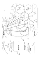
図5は、基地局BS1(110−1)およびBS8(110−8)の送信電波を図1に比べて下げた場合の無線通信網の構成および動作例を示すブロック図である。図1では基地局BS1(110−1)のセルラ(100−1)は、隣接する基地局BS2〜7(110−2〜7)のセルラ(100−2〜7)とオーバーラップしていたが、図5に示すような状態では基地局BS1(110−1)の送信電波を下げたためにセルラ(100−1)が狭まり、他のセルラとオーバーラップしない。基地局BS8(110−8)のセルラ(100−8)も同様に基地局BS2およびBS3(110−2と3)のセルラ(100−2と3)とオーバーラップしない。
【0038】
これにより、端末MS1(300−1)は基地局BS1(110−1)との通信路(900−2)を設定できなくなり、基地局BS2(110−2)とのみ通信路を設定可能になる。端末MS1(300−1)は図1では通信品質のよい通信路(900−2)を選択していたが、図5に示すような状態では設定できなくなったため、基地局制御部(200−1)に備えられているDHT(210−2)により通信路(910−2)に切換えられる。端末MS2についても同様の理屈で通信路(900−1)から通信路(910−1)に切換えられる。また、基地局制御部(200−1)は、切り換えられた通信路からの信号(920−1、2)を用いて着信先端末と通信する。
【0039】
このように基地局の送信電波を制御することにより、通信サービス提供中の通信路を特定の基地局から隣接の基地局に無瞬断で切換え、該基地局では通信サービスが提供されていない状態を作り出すことが可能になる。このような状態においてソフトウェアの更新を行い、ソフトウェア更新後は送信電波を元に戻す。この処理を、所定の規則でソフトウェアを更新する基地局の選択を繰返し行い、選択された基地局に対して実行することによって、通信サービスが途断することなく無線通信網内の基地局ソフトウェア更新が可能になる。
【0040】
図6は、基地局のソフトウェア更新動作の一例を説明する動作説明図である。網管理装置(250)はまずソフトウェアを更新する基地局を所定の規則で選択する(グループ化)処理(7−1)を行う。以下、処理(7−1)において選択した基地局の集まりを基地局グループ1(800−1)と称する。なお、基地局選択の詳細については後述する。網管理装置(250)が基地局グループ1に対してソフトウェア転送を要求する処理(7−2)を行うと、基地局グループ1(800−1)に属する各基地局は新しいソフトウェアを網管理装置(250)から取得する処理(7−3)を行い、ソフトウェア転送完了応答を網管理装置(250)に送信する処理(7−4)を行う。網管理装置(250)は、基地局グループ1(800−1)以外の基地局(800−x)に対してサービス停止動作を禁止する処理(7−5)を行い、基地局グループ1(800−1)に対してソフトウェア更新要求を送信する処理(7−6)を行う。なお、上述の処理(7−5)は省略することもできる。
【0041】
基地局グループ1(800−1)に属する基地局は、該要求を受信すると送信電力を徐々に下げる処理(7−7)を行う。これにより該基地局に接続されていた呼は順次隣接基地局にハンドオーバする。基地局グループ1(800−1)に属する基地局は、自基地局に接続されている呼(通信サービス提供中の通信路)がゼロになったことを確認する処理(7−9)を行う。なお、各基地局は、メモリ(112)もしくは記憶装置(113)に記憶されている呼の情報を参照することにより、または、基地局制御部(200)で管理されている呼の情報を参照することにより、自基地局に接続されている呼がゼロになったことを確認することができる。呼がゼロになったことの確認後、自基地局をリセットする処理(7−10)により新しいソフトウェアを読み込む処理(7−11)を行い、基地局を再開する処理(7−12)を行う。基地局グループ1(800−1)に属する基地局は、更に自基地局の送信電力を徐々に上げる処理(7−13)を行い、元の送信電力に達したところで網管理装置(250)へソフトウェア更新完了応答を送信する処理(7−14)を行う。
【0042】
網管理装置(250)は、基地局グループ1(800−1)に属する全ての基地局からソフトウェア更新完了応答を受信した後に、ソフトウェアを更新する基地局を新たに選択(グループ化)する処理(7−15)を行う。以下、選択した基地局の集まりを基地局グループ2(800−2)と称する。網管理装置250はこの基地局グループ2(800−2)に対してソフトウェア転送を要求する処理(7−16)を行う。なお、処理(7−16)は、上述の処理(7−2)と同様である。網管理装置(250)は、基地局グループ1(800−1)に対して行った処理(7−2〜7−14)と同様の処理を基地局グループ2(800−2)に対しても行う。これらの処理をどの基地局グループにも属さない基地局がなくなるまで繰返すことによって、全ての基地局のソフトウェア更新を行うことができる。
【0043】
ソフトウェアを更新する基地局に接続され、サービスが提供中である呼の通信路を隣接基地局に切換えるためには、隣接基地局を同時にソフトウェア更新しないほうがよい。よって、ソフトウェア更新対象基地局の選択には所定の規則が必要になる。
【0044】
図7は、網管理装置における、ソフトウェアを更新する基地局の選択動作の一例を示す動作フロー図である。図7に示すフロー図は、図6における処理(7−1)および処理(7−15)の詳細フローである。図7に示す動作により、網管理装置(250)は、基地局グループn(nは1以上の整数)を選択作成する。
【0045】
まず、網管理装置(250)は、メモリ(252)から呼接続数を読み込む処理(8−1)を行う。なお、網管理装置(250)は、呼接続数を基地局制御部(200)又は各基地局(110)から読み込んでも良い。次に、網管理装置(250)は、どのグループにも属していない基地局、かつ、処理8−4および処理8−8で選択候補から除外されていない基地局を基地局グループnの候補とする処理(8−2)を行い、その候補の中から呼接続数の最も小さな基地局(もしくはあらかじめ定められた呼接続数より呼接続数が少ない基地局)を割り出し、該基地局を「基地局A」とする処理(8−3)を行う。
【0046】
次に、網管理装置(250)は、「基地局A」の呼接続数があらかじめ定められた値よりも大きい場合は、該基地局を選択候補から除外する処理(8−4)を行う。一方、大きくない場合は、網管理装置(250)は、「基地局A」を基地局グループnに属させる処理(8−6)を行い、「基地局A」の隣接基地局情報をメモリ(252)から取得する処理(8−7)を行う。「基地局A」の隣接基地局は、基地局グループnの候補から外す処理(8−8)により選択候補から除外される。なお、上述の処理(8−4)で該基地局を選択候補から除外した場合は、処理(8−6)から処理(8−8)までの処理は行わなくてもよい。
【0047】
網管理装置(250)は、その後、基地局グループnの候補となる基地局が残っているかどうか判断する処理(8−9)を行い、その結果、候補となる基地局がまだ残っていると判断した場合は処理(8−2)へ戻り、再び処理(8−2)以下の処理を行う。一方、残っていない場合、網管理装置(250)は、基地局グループnの作成選択終了処理(8−10)を行う。
【0048】
以上の処理を実行することにより、ソフトウェア更新を行う基地局の隣接基地局を同時にソフトウェア更新することがなくなるので、ソフトウェア更新を行う基地局にて通信サービス提供中の呼は、隣接基地局に通信路を切換えることが可能になる。
【0049】
図8、9、10、11および12は、図7に示した基地局選択動作の様子を説明する説明図(1)〜(5)である。網管理装置(250)のメモリ(252)には、例えば、図8、9、10、11および12のいずれかに示すような、基地局番号、基地局に接続されている呼数(呼接続数)、隣接基地局番号およびグループ情報を含むテーブルが存在する。このテーブルを用いて、図7に示した処理を行うことにより、同時にソフトウェア更新を行う基地局のグループを選択することができる。以下に図8、9、10、11および12を用いて、基地局選択動作について説明する。
【0050】
図8は、基地局グループ選択を行う前の状態を表す図である。まず、基地局グループ1の作成について説明する。図中の「グループ」列の「0」は未だその基地局がどのグループにも属していない、すなわち、選択候補となることを表している。網管理装置(250)は、図7の選択動作に従い、処理8−1〜8−6により最初に最も呼接続数が5と少ない基地局1(もしくはあらかじめ定められた呼接続数(この例では、例えば15)よりも呼接続数が少なくかつ最初にみつかった基地局1)を選択し、グループ番号欄に「1」を付与する。
【0051】
次に、図7の処理8−7〜8−8により、基地局1に対応する隣接基地局番号を参照し、該基地局番号に該当する基地局のグループ番号欄に「×」を付与する。ここで、「×」は、選択候補から除外されていることを示す。
【0052】
図9は、そのときの状態を表している。
さらに、図7の処理8−9により、網管理装置(250)は、選択候補となる基地局が残っているので、処理8−2以降の基地局の選択を再度行う。
【0053】
網管理装置(250)は、「0」が付与された基地局(あるいは「1」および「×」が付与された基地局以外の基地局)から、最も呼接続数が6と少ない基地局21(もしくはあらかじめ定められた呼接続数(この例では、例えば15)よりも呼接続数が少なくかつ最初にみつかった基地局21)を選択し(処理8−2〜8−4)、グループ番号欄に「1」を付与し(処理8−6)、基地局21の隣接基地局番号22を参照して(処理8−7)、基地局22のグループ番号欄に「×」を付与する(処理8−8)。
【0054】
更に、処理8−9を経て処理8−2以降により、グループ番号欄に「0」が付与された基地局(あるいは「1」および「×」が付与された基地局以外の基地局)から、最も呼接続数が11と少ない基地局8(もしくはあらかじめ定められた呼接続数(例えば15)よりも呼接続数が少なくかつ最初にみつかった基地局8)を選択し、グループ番号欄に「1」を付与する。この処理をグループ番号欄が「1」および「×」でない基地局がなくなるまで続けることによって基地局グループ1を作成選択することができる(その後、処理8−10へ移行)。
【0055】
図10は、基地局グループ1の選択を完了したときの図である。網管理装置(250)は、グループ番号欄に「1」が付与されている基地局に対して、ソフトウェア更新の処理を行う。また、網管理装置(250)は、基地局グループ1に対するソフトウェア更新の終了後、グループ番号欄の「×」を、例えば「0」等の更新済み又は選択候補であることを示すデータに変更し、上述と同様にして基地局グループ2を選択する。この例では、グループ番号欄に記憶されている「0」は、ソフトウェアの更新がされていないこと(選択候補であること)を示し、「1」などのグループ番号はソフトウェアの更新がされていることを示す。
【0056】
図11は、基地局グループ2の選択を完了したときの図である。図11においても、網管理装置(250)は、図10の基地局グループ1を選択した場合と同様にして、基地局を選択しグループ番号「2」もしくは「×」を付与する。図11の場合、基地局がグループ2に選択される順番は図7に示す選択動作(呼接続数が最小の基地局を選択する場合)に従うと基地局5、基地局22、基地局7、基地局3になる。
【0057】
なお、図10と図11では基地局に接続している呼の数が異なる。これは基地局グループ1のソフトウェア更新時と基地局グループ2のソフトウェア更新時では時間に開きがあるために呼が移動するなどして接続呼数が変動していることを意味している。本実施の形態では、基地局グループの選択処理中に参照する呼接続数が変動しないように、選択処理中において呼接続数を読み込み、読み込んだ呼接続数を参照して選択処理を行っている。なお、これに限らず、変動する呼接続数を参照して選択処理を行ってもよい。
【0058】
図12は、基地局グループ3の選択を完了したときの図である。図12においても網管理装置(250)は、図10および図11の基地局グループ1および2を選択した場合と同様にして、基地局を選択しグループ番号3もしくは「×」を付与する。図12の場合、基地局がグループ3に選択される順番は、図7に示す選択動作(呼接続数が最小の基地局を選択する場合)に従うと基地局6、基地局4、基地局2になる。図12のように、グループ選択を完了した時点でもはや「×」の基地局が存在しない場合は、全ての基地局にグループ番号が付与され、基地局グループ作成が完了したことを意味する。
【0059】
図13は、ソフトウェアを更新する基地局における送信電力減少処理の動作例を示す動作説明図である。図13の動作例は、図6に示す処理(7−7)の詳細処理である。ソフトウェアを更新する基地局(110)では、網管理装置(250)からのソフトウェア更新要求を受けて、CPU(111)が送信電力減少処理(12−1)を開始する。CPU(111)は、あらかじめ定められている電力減少幅だけ送信電力を減少させるよう無線IF(116)に要求する処理(12−2)を行う。無線IF(116)は、該要求を受けて送信電力を減少させる処理(12−3)を実行し、送信電力減少後の送信電力値をCPU(111)に通知する処理(12−4)を行う。CPU(111)は、無線IF(116)から通知された電力値が予め設定された送信電力の下限値か否か判断する処理(12−5)を行い、下限値でなければ処理(12−2)に戻り、処理(12−2)以下の処理を再び行う。一方、CPU(111)は、通知された電力値が下限値に達していたら、送信電力減少の終了処理(12−6)を行う。
【0060】
これらの処理により、基地局(110)は、自基地局の送信電力を徐々に下げ、自基地局にて通信サービスを提供している通信路を隣接基地局に切換え、自基地局では通信サービスが提供されていない状態を作り出すことが可能になる。
【0061】
次に本実施の形態を適用するもう一つの無線通信網について以下に述べる。
図14は、本実施の形態を適用する無線通信網の構成例を示すブロック図である。無線通信網(10’)は、以下のように構成され端末間の通信を行う。
複数の移動可能な端末MS1、MS2(300−1、2)と、複数の無線通信装置(以下、基地局と称す)BS1〜BS8(110’−1〜8)とは無線通信路(図示せず)で接続される。具体的には、各基地局BSは、複数のセクタ(130−1〜3)と呼ばれる電波の到達範囲を備え端末MSとCDMAを用いた無線通信を行う。なお、この例ではαセクタ、βセクタ、γセクタの3つが示されるが、これに限らず、基地局は適宜のセクタ数を有することができる。図示していないが、実際の各基地局のセルラは互いにオーバラップしており、端末MS1(300−1)からは基地局BS1のαセクタとγセクタで通信路(900−2と910−2)が設定可能である。尚、本実施の形態では、これら複数の基地局BS1〜8(110’−1〜8)が端末MSと通信できるエリアを移動体通信網400’と称する。
【0062】
移動体通信網(400’−1)の各基地局BS1〜8(110’−1〜8)は、基地局制御部(制御装置)(200−1)と主信号通信路(500−1)で接続される。基地局制御部(200)は、以下で詳述するが、例えば、3GPPのTR25.832の5.2.1章(非特許文献1参照)で定められたようなソフトハンドオーバを行うダイバーシティハンドオーバユニットDHT(210)を備え、複数の通信路(900、910)から通信品質の良い1つの通信路を選択して通信を行う。
端末MS1(300−1)からの着信先が同じ移動体通信網(400’−1)にあれば、基地局制御部(200−1)は、配下の基地局BS1〜8(110’−1〜8)のいずれかにDHT(210)が選択した信号(930)を戻して着信先端末MSと通信する。一方、基地局制御部(200−1)は、着信先が別の移動体通信網(400’−2:詳細構成は400’−1とほぼ同じなので省略する)の端末であれば、基地局制御部(200)同士を接続する通信網(150)を介して信号を基地局制御部(200−2)と移動体通信網(400’−2)を用いて着信先端末とを送受信する。尚、上記通信網(150)は、公衆網、専用線網、私設網のいずれであっても構わない。また、移動体通信網(400’−2)は、有線通信網とそれに固定的に設置される端末とで構成された所謂固定網であっても構わない。
【0063】
網管理装置(250)は、通信網(10’)に備えられた基地局BS(110’)及び基地局制御部(200)と監視・保守等の制御信号を送受信する制御信号通信路(600)で接続され、例えば、基地局(110’)のソフトウェアの更新を行う等、通信網(10’)の設備全体を管理・制御するための装置である。尚、基地局BS(110’)、基地局制御部(200)、網管理装置(250)、各基地局BS内のセクタ数は、図14に示す数に限らず、適宜の数備えることができる。
図15は、通信網に備えられた基地局の構成例を示すブロック図である。基地局(110’)は以下のように構成され端末および基地局制御部間の接続や、網管理装置との通信を行う。
基地局(110’)は、端末MS(300)から図示していない無線通信路を介して送信された信号(電波信号)をアンテナ(119’−1)で受信すると、無線IFユニット(116−1)で電気信号への変換等終端処理を行う。終端処理後の信号に対して各種通信サービスを行う為の処理(例えば、呼制御等の通信処理)を通信処理ユニット(117−1)で実施し、回線IFユニット(118)で基地局制御部(200)とのインタフェース整合をとった後、この信号を主信号通信路(500)を介して基地局制御部(200)に送信する。基地局(110’)は、基地局制御部(200)からの信号は上記プロセスと逆のプロセスにより端末MS(300)へ送信する。以上はセクタα制御部(120−1)が信号(電波信号)を送受信した場合であるが、セクタβ制御部(120−2)およびセクタγ制御部(120−3)が信号(電波信号)を送受信した場合も同様である。
【0064】
基地局(110’)の装置管理部(121)のCPU(111−4)は、メモリ(112−4)に蓄積された制御プログラムや、記憶装置(113)に蓄積された無線通信網(10’)の運用に必要なデータ(例えば、端末の情報他)を用いて、各セクタ制御部(120−1〜3)および回線IF(118)などの基地局(110’)全体を制御するものである。
基地局(110’)の各セクタ制御部(120−1〜3)のCPU(111−1〜3)は、メモリ(112−1〜3)に蓄積された制御プログラムを用いて、装置管理部(121)からの指示を受けて、セクタそれぞれの無線IFユニット(116−1〜3)および通信処理(117−1〜3)を制御する。
又、上記これらのユニット等は内部バス(115)で接続されている。内部バス(115)に接続されたI/O(114)は、網管理装置(250)とのインタフェースであり、通信網(10’)の運用・保守等の制御に必要な制御信号(命令他)や各種データを制御信号通信路(600)を介して送受信するものである。尚、I/O(114)を備えずに主信号通信路(500)を用いて、主信号通信路(500)を介して送受信される信号にこれらの制御信号やデータを付加し、回線IFユニット(118)経由で送受信する構成としても良い。
【0065】
この基地局(110’)は、無線通信網(10’)で提供する通信サービスの更新に伴い、装置管理部(121)のCPU(111−4)が、装置管理部(121)および各セクタ制御部(120−1〜3)のメモリ(112−1〜4)に格納されるソフトウェア(制御プログラム他)、あるいは、無線IFユニット(116−1〜3)・通信処理ユニット(117−1〜3)・回線IFユニット(118)に格納されるファームウェア(制御プログラム他)を、後述するような手順と動作で、基地局が使用中(運用中、あるいは、オンライン状態)のままで更新するものである。尚、以下の本実施の形態では、基地局が使用中のままで上述したようなソフトウェアやファームウェアを更新する動作をオンラインアップグレードと称することがある。
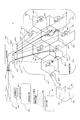
図16は各基地局BS1〜8(110’−1〜8)のαセクタ(120−1)の送信電波出力を図14に比べて下げた場合の無線通信網の構成および動作例を示すブロック図である。図14では基地局BS1(110’−1)のαセクタは、端末MS1(300−1)が位置するエリアをカバーしていたが、図16では各基地局のαセクタの送信電波出力を下げたために、基地局BS1(110’−1)のαセクタがカバーするエリアが狭まり端末MS1(300−1)が位置するエリアをカバーできなくなる。基地局BS8(110’−8)のαセクタも同様に端末MS2(300−2)が位置するエリアをカバーできない。これにより、端末MS1(300−1)は基地局BS1(110’−1)のαセクタとの通信路(900−2)を設定できなくなり、基地局BS1(110’−1)のγセクタとのみ通信路を設定可能になる。端末MS1(300−1)は図14では通信品質のよい通信路(900−2)を選択していたが、図16では設定できなくなったため、基地局制御部(200−1)に備えられているDHT(210−2)により通信路(910−2)に切換えられる。端末MS2についても同様の理屈で通信路(900−1)から通信路(910−1)に切換えられる。また、基地局制御部(200−1)は、切り換えられた通信路からの信号(920−1、2)を用いて着信先端末と通信する。
【0066】
このように基地局の送信電波を制御することにより、通信サービス提供中の通信路を各基地局の特定セクタから無瞬断で切換え、該セクタでは通信サービスが提供されていない状態を作り出すことが可能になる。このような状態においてソフトウェアの更新を行い、ソフトウェア更新後は送信電波を元に戻すという処理を各基地局共に複数のセクタ(α、βおよびγ)制御部に対して順番に行うことによって、無線通信網内の基地局のソフトウェアを通信サービスが途断することなくソフトウェア更新が可能になる。
図17は基地局のソフトウェア更新動作の一例を説明する動作説明図である。網管理装置(250)は各基地局に対してソフトウェア転送指示処理(17−1)を行う。各基地局は新しいソフトウェアを取得する処理(17−2)により新しいソフトウェアを取得し、網管理装置(250)にソフトウェア転送完了を応答する処理(17−3)を行う。次に網管理装置(250)は各基地局に対してソフトウェア更新指示処理(17−4)を行う。セクタα制御部のソフトウェア更新処理(17−5)、セクタβ制御部のソフトウェア更新処理(17−6)、セクタγ制御部のソフトウェア更新処理(17−7)を順次行い、装置管理部のソフトウェア更新処理(17−8)終了後、網管理装置へソフトウェア更新完了を応答する処理(17−9)を行う。各セクタ制御部のソフトウェア更新処理(17−5〜7)の詳細処理を図18に、更に詳細な処理を図19に示し、また装置管理部のソフトウェア更新処理(17−9)の詳細処理を図20に示している。
【0067】
図18は各セクタ制御部のソフトウェア更新処理(17−5〜7)の詳細処理を説明する動作フロー図である。まず装置管理部(121)はセクタX(Xはα、βまたはγ)制御部(120)に対して送信電力減少要求処理(18−1)を行う。セクタX制御部(120)は送信電力を徐々に下げる処理(18−2)を行う。これによりセクタXが処理していた呼は隣接するセクタにハンドオーバし、該呼の通信サービスが継続される。セクタX制御部(120)は、送信電力減少処理を完了すると、完了を装置管理部(121)に応答する処理(18−3)を行う。装置管理部(121)はセクタXに接続されている呼がゼロであることを確認する処理(18−4)を行った後にセクタX制御部(120)のソフトウェア更新をセクタX制御部(120)に要求する処理(18−5)を行う。セクタX制御部(120)はソフトウェア更新要求を受けると自身のリセット処理(18−6)を行うことによって、新しいソフトウェアを読込む処理(18−7)を行う。その後、セクタXの再開処理(18−8)およびセクタXの送信電力を徐々に上げる処理(18−9)をセクタX制御部(120)が行うことによって、セクタXの通信処理が再び可能になる。セクタXの送信電力を徐々に上げる処理(18−9)が完了したところで、セクタX制御部(120)は装置管理部(121)に対してソフトウェア更新完了を応答する処理(18−10)を行う。なお、図18の処理は、呼が隣接セクタへハンドオーバできるようにするために、各セクタ(α、βまたはγ)制御部に対して同時には行わず、図17の各セクタ制御部のソフトウェア更新処理(17−5〜7)に示すように順次行うこととする。
図19は、図18で示した送信電力を徐々に下げる処理(18−2)を詳しく説明した動作フロー図である。装置管理部のCPU(111−4)から送信電力減少要求(18−1)を受けて、セクタX制御部(120)のCPU(111−1〜3)が送信電力を減少する処理(19−1)を開始する。CPU(111−1〜3)はあらかじめ定められている電力減少幅だけ送信電力を減少させるよう無線IF(116−1〜3)に要求する処理(19−2)を行う。無線IF(116−1〜3)はそれを受けて送信電力減少処理(19−3)を実行し、送信電力減少後の送信電力値をCPU(111−1〜4)に通知する処理(19−4)を行う。CPU(111−1〜3)は無線IF(116−1〜3)から通知された電力値が送信電力の下限値か否か判断する処理(19−5)を行い、もしも下限値でなければ処理(19−2)を再び行う。もしも通知された電力値が下限値に達していたら送信電力減少の完了応答処理(18−3)を行う。
【0068】
これらの処理により、基地局は自基地局内のセクタの送信電力を徐々に下げることができ、自基地局にて通信サービスを提供している通信路を隣接セクタ若しくは隣接基地局に切換え、自基地局の該当セクタでは通信サービスが提供されていない状態を作り出した上でソフトウェアを更新することが可能になる。
図20は図17における基地局内装置管理部(121)のソフトウェア更新処理(17−9)の詳細を説明した動作フロー図である。装置管理部(121)は自身のリセット処理(20−1)により新しいソフトウェアを読込み(20−2)および装置管理部の再開処理(20−3)を行う。装置管理部(121)をリセットしても主信号通信路(500)には影響しないため、装置管理部(121)のソフトウェア更新中においても通信サービスが途断することはない。
【発明の効果】
本発明によれば、無線通信網が各種通信サービスを提供中であっても該無線通信網内の各無線通信装置に供えたソフトウェアを更新することのできる無線通信装置及び無線通信網を提供することができる。また、本発明によると、提供中の通信サービスを途絶させることなく、ソフトウェアを更新することのできる無線通信装置及び無線通信網を提供することができる。さらに、本発明によると、これら装置及び方法を簡単で経済的な構成と手順で実現することができる。
【図面の簡単な説明】
【図1】無線通信網の構成および動作例を示すブロック図である。
【図2】基地局の構成例を示すブロック図である。
【図3】基地局制御部の構成例を示すブロック図である。
【図4】網管理装置の構成例を示すブロック図である。
【図5】無線通信網の構成および基地局の送信電波を下げた場合の動作例を示すブロック図である。
【図6】基地局のソフトウェア更新動作の一例を説明する動作説明図である。
【図7】ソフトウェアを更新する基地局の選択動作の一例を示す動作フロー図である。
【図8】基地局選択動作の様子を説明する説明図(1)である。
【図9】基地局選択動作の様子を説明する説明図(2)である。
【図10】基地局選択動作の様子を説明する説明図(3)である。
【図11】基地局選択動作の様子を説明する説明図(4)である。
【図12】基地局選択動作の様子を説明する説明図(5)である。
【図13】ソフトウェアを更新する基地局の動作例を示す動作説明図である。
【図14】一つの基地局が複数セクタを有する無線通信網の構成および動作例を示すブロック図である。
【図15】複数セクタを有する基地局の構成例を示すブロック図である。
【図16】一つの基地局が複数セクタを有する無線通信網の構成および別の動作例を示すブロック図である。
【図17】基地局のソフトウェア更新動作の一例を説明する動作説明図である。
【図18】ソフトウェアを更新する基地局の動作例の一部詳細を示す動作説明図である。
【図19】ソフトウェアを更新する基地局内部のセクタ制御部の動作例を示す動作説明図である。
【図20】ソフトウェアを更新する基地局内部の装置制御部の動作例を示す動作説明図である。
【符号の説明】
10 無線通信網
100 セルラ
110 無線通信装置(基地局)
111 CPU
112 メモリ
113 記憶装置
114 I/O
115 内部バス
116 無線IFユニット
117 通信処理ユニット
118 回線IFユニット
119 アンテナ
120 セクタ制御部
121 装置管理部
130 セクタ
150 通信網
200 基地局制御部
210 ダイバーシティハンドオーバユニット
250 網管理装置
300 端末
400 移動体通信網
500 主信号通信路
600 制御信号通信路[0001]
BACKGROUND OF THE INVENTION
The present invention Wireless communication apparatus and wireless communication network In particular, for updating software without interrupting communication services. Wireless communication apparatus and wireless communication network About.
[0002]
[Prior art]
In addition to the conventional wired communication network, introduction of a wireless communication network using a wireless terminal and a wireless communication device has been rapidly promoted. Wireless communication networks began with the introduction of a TDMA (Time Division Multiple Access) communication network that performs time-division multiplexing of signals such as voice, and in the future, CDMA that performs communication by code-multiplexing signals such as voice with spreading codes. (Code Division Multiple Access) It is expected that communication networks will become widespread, and anytime, anywhere, and anyone will be able to communicate. The communication network operates by software provided in each communication device in the network and provides various communication services such as voice communication and data communication to the user of the wireless terminal. The contents of the communication service provided by the communication network are as follows. Every time it evolves, it is necessary to update the software of the communication device as appropriate.
[0003]
A wireless communication device called a base station used in a wireless communication network is an interface device between a wireless terminal and a communication network, and requires software updates as described above to provide various communication services. Various software update methods have been proposed (see, for example,
[0004]
Further, conventionally, in a system for interconnecting a wireless communication network and another communication network, an apparatus for performing diversity and handover for selectively combining signals having excellent call quality based on signals transmitted to and received from a plurality of base stations is provided. It is known (see, for example, Patent Document 5). In a CDMA communication network, a soft handover technique is known in which signals are combined or a communication path is selected by communication with a plurality of base stations when the base station is changed, and the communication path is switched without instantaneous interruption ( For example, refer nonpatent literature 1).
[0005]
[Patent Document 1]
Japanese Patent Laid-Open No. 10-63498
[Patent Document 2]
Japanese Patent No. 2980201 (Japanese Patent Laid-Open No. 10-320210)
[Patent Document 3]
JP-A-7-319683
[Patent Document 4]
JP 2001-56756 A
[Patent Document 5]
JP 2001-16227 A
[Non-Patent Document 1]
"3G TR25.832 V4.0.0", 3GPP issued, March 2001, chapter 5.2.1
[0006]
[Problems to be solved by the invention]
In general communication networks, it is important to ensure reliability to prevent communication disruption, so software that provides communication services or controls the operation of the communication network can be updated even during operation, for example, As described in
[0007]
On the other hand, in a wireless communication network, communication with a wireless terminal is performed in an area called cellular in a range where radio waves of a base station can reach, and a cellular having a radius of about several kilometers is generally used. That is, since the number of users and the coverage area to be accommodated are significantly smaller than those of a conventional wired communication network (switching network), a large number of these base stations must be arranged in a wide range in order to provide a communication service in a wide range. Therefore, installing each of these many base stations in a redundant manner as in the wired communication network equipment described in the above document significantly impairs the economics of the communication network. Furthermore, it is necessary to assign a plurality of frequency bands and CDMA spreading codes, and finite resources are wasted, and the service providing capability such as the number of users is reduced. For this reason, for example, as shown in
[0008]
However, the above-described method will further increase the burden on the operator who manages the wireless communication network in the future, which may make it difficult to provide an economical wireless communication network and communication service. For example, as the wireless communication network becomes more widespread in the future and the number of terminals used by users increases, the traffic of each base station constantly fluctuates because these terminals move and are used. Furthermore, with the globalization of communication networks, the use of communication networks that do not care about time differences will increase, and there is no guarantee that traffic will be low even in Japan at midnight. This makes it difficult to select a base station with low traffic and to protect important calls, increasing the burden on the operator. Furthermore, from the user's point of view, there is an increased chance of communication service disruption (or communication disconnection) due to software updates, and a decrease in reliability and serviceability due to delays in receiving new services due to update delays. . So-called online communication device software is provided so that the latest communication service can be provided without interrupting the communication service being provided even in a wireless communication network in which the wireless communication device (base station) does not have a redundant configuration. There is a need for a wireless communication device that can be updated, a wireless communication network, and an operation method (software update method) thereof.
[0009]
In view of the above, the present invention can update software provided to each wireless communication device in a wireless communication network even when the wireless communication network is providing various communication services. Wireless communication apparatus and wireless communication network The purpose is to provide. Another object of the present invention is to realize software update without interrupting a communication service being provided. Furthermore, it is an object of the present invention to realize these apparatuses and methods with a simple and economical configuration and procedure.
[0010]
[Means for Solving the Problems]
In order to achieve the above-mentioned object, the present invention pays attention to a soft handover technique defined in a CDMA communication network (for example, refer to Chapter 5.2.1 of 3GPP TR25.832, Non-Patent Document 1) and a wireless communication apparatus and a wireless A communication network is configured and these operation methods are provided. Specifically, in a CDMA communication network, paying attention to the fact that a communication path from a certain terminal to a plurality of base stations is set, and one having a good communication state is selected and used for communication with an actual counterpart, By switching the state of the transmitted radio wave of the base station that is trying to update the communication path, the communication path providing the communication service is switched from the corresponding base station to another base station without interruption, and the communication service is provided at the corresponding base station. The software is updated in this state, and after the software update, the state of the transmission radio wave is restored. The base station selection is repeated according to a predetermined rule, and the software of the base station in the wireless communication network is updated without interruption of the communication service.
[0011]
According to the first solution of the present invention,
In a wireless communication device that communicates between a wireless terminal and a wired communication network in a wireless communication network that can be handed over,
A wireless interface for communicating with a wireless terminal;
A wired interface for communicating with a wired communication network;
A communication processing unit for performing processing for providing a communication service to a wireless terminal via the wireless interface and the wired interface;
A control unit for controlling the device;
With
The controller is
Change the state of the radio wave transmitted by the wireless interface according to a predetermined rule,
Update the software that has been set in advance to the software received via the wired interface,
After the software update, return the radio wave transmission status of the wireless interface
The wireless communication device is provided.
[0012]
According to the second solution of the present invention,
In a wireless communication network capable of handover,
A wireless communication device for communicating between a wireless terminal and a wired communication network;
A control unit that has a handover unit that selects one or a plurality of signals according to a radio wave state from signals received through a plurality of settable communication paths, and that communicates with the wireless communication device;
A network management device for managing the network;
With
The network management device
A wireless communication device group is created by selecting one or a plurality of wireless communication devices whose software is to be updated according to a predetermined rule,
Sending update software and an update request to the wireless communication devices belonging to the created wireless communication device group,
The wireless communication device
Receiving software and an update request transmitted from the network management device;
In accordance with the received update request, change the state of the transmitted radio wave so that the communication device providing the communication service is switched to the other wireless communication device without interruption by the control device,
Update the set software to the received software,
After the software update, return the transmitted signal status
The wireless communication network is provided.
[0013]
According to the third solution of the present invention,
A wireless communication device comprising: a wireless communication device that communicates between a wireless terminal and a wired communication network; a control device that has a handover unit for performing handover; communicates with the wireless communication device; and a network management device that manages the network. A software update method for updating software of a wireless communication device in a communication network,
The network management device or the control device creates a wireless communication device group by selecting one or more wireless communication devices whose software is to be updated according to a predetermined rule;
The network management device or the control device transmits software for updating and an update request to the wireless communication devices belonging to the created wireless communication device group;
The wireless communication device receives the update request, and changes the state of the transmission radio wave so as to switch the communication path providing the communication service to other wireless communication devices without interruption.
The wireless communication device updates the set software to the received software;
The wireless communication device includes a step of returning the state of the transmitted radio wave after updating the software.
The software update method is provided.
According to the fourth solution of the present invention,
In a wireless communication network capable of handover,
A wireless communication device having a plurality of sectors and communicating between a wireless terminal and a wired communication network;
A control unit that has a handover unit that selects one or a plurality of signals according to a radio wave state from signals received through a plurality of settable communication paths, and that communicates with the wireless communication device;
A network management device for managing the network;
With
The network management device
Sending software and update request for updating to one or a plurality of the wireless communication devices for updating software;
Each of the wireless communication devices
Receiving software and an update request transmitted from the network management device;
In accordance with the received update request, at least one sector of the plurality of sectors is sequentially selected and selected so that the wireless communication device can be switched to the other wireless communication device without interruption by the control device. Change the status of the transmitted signal for
Update the set software to the received software,
After the software update, return the transmitted signal status
The wireless communication network is provided.
According to the fifth solution of the present invention,
A wireless communication device having a plurality of sectors and communicating between a wireless terminal and a wired communication network, a control device having a handover unit for performing handover, and communicating with the wireless communication device, and a network for managing the network In a wireless communication network comprising a management device, a software update method for updating software of a wireless communication device,
The network management device or the control device transmits the software for updating and the update request to one or a plurality of wireless communication devices that update the software;
Each wireless communication device receives the update request, and sequentially selects at least one of a plurality of sectors so that the communication path providing the communication service can be switched to another wireless communication device without interruption. Changing the state of the transmitted radio wave for the selected sector;
The wireless communication device updates the set software to the received software;
The wireless communication device includes a step of returning the state of the transmitted radio wave after updating the software.
The software update method is provided.
[0014]
DETAILED DESCRIPTION OF THE INVENTION
Hereinafter, a configuration of a wireless communication apparatus and a wireless communication network and a software update method according to the present embodiment will be described in detail with reference to the drawings.
FIG. 1 is a block diagram illustrating a configuration example of a wireless communication network to which the present embodiment is applied. The wireless communication network (10) is configured as follows and performs communication between terminals.
[0015]
A plurality of mobile terminals MS1, MS2 (300-1, 2) and a plurality of wireless communication apparatuses (hereinafter referred to as base stations) BS1 to BS8 (110-1 to 8) are wireless communication paths (not shown). ). Specifically, each base station BS has a radio wave reachable range called cellular (100-1 to 8), and performs radio communication using, for example, the terminal MS and CDMA. Although not shown, the cellular of each base station actually overlaps, for example, communication from the terminal MS1 (300-1) via a plurality of base stations BS1 and 2 (110-1 and 2). Paths (900-2 and 910-2) can be set. In the present embodiment, an area where the plurality of base stations BS1 to BS8 (110-1 to 8) can communicate with the terminal MS is referred to as a
[0016]
Each base station BS1 to 8 (110-1 to 8) of the mobile communication network (400-1) is connected to the base station control unit (control device) (200-1) via the main signal communication path (500-1). Is done. The base station control unit (200), which will be described in detail below, is a diversity handover unit that performs soft handover as defined in, for example, Chapter 5.2.1 of 3GPP TR25.832 (see Non-Patent Document 1). A DHT (210) is provided, and communication is performed by selecting one communication path with good communication quality from a plurality of communication paths (900, 910).
[0017]
If the destination of the terminal MS1 (300-1) is in the same mobile communication network (400-1), the base station controller (200-1) controls the subordinate base stations BS1-8 (110-1-8). ), The signal (930) selected by the DHT (210) is returned to communicate with the destination terminal MS. On the other hand, the base station control unit (200-1) is a base station control unit if the destination is a terminal of another mobile communication network (400-2: detailed configuration is almost the same as 400-1). (200) Through the communication network (150) that connects the two, the destination station by transmitting and receiving the signal (930-2) using the base station controller (200-2) and the mobile communication network (400-2) Communicate with the terminal. The communication network (150) may be a public network, a private line network, or a private network. Further, the mobile communication network (400-2) may be a so-called fixed network composed of a wired communication network and terminals fixedly installed therein.
[0018]
The network management device (250) is a control signal communication path (600) that transmits and receives control signals such as monitoring and maintenance to and from the base station BS (110) and the base station control unit (200) provided in the communication network (10). For example, it is a device for managing and controlling the entire equipment of the communication network (10) such as updating software of the base station (110). The base station BS (110), the base station control unit (200), and the network management apparatus (250) are not limited to the numbers shown in FIG.
[0019]
FIG. 2 is a block diagram illustrating a configuration example of a base station provided in the communication network. The base station (110) is configured as follows, and performs connection between the terminal and the base station control unit and communication with the network management device.
[0020]
When the base station (110) receives a signal (radio signal) transmitted from the terminal MS (300) via a wireless communication path (not shown) by the antenna (119), the base station (110) converts the signal to an electrical signal by the wireless IF unit (116). Terminal processing such as conversion is performed. Processing for performing various communication services (for example, communication processing such as call control) on the signal after termination processing is performed by the communication processing unit (117), and the base station control unit (200) by the line IF unit (118). ), The signal is transmitted to the base station control unit (200) via the main signal communication path (500). The base station (110) transmits a signal from the base station control unit (200) to the terminal MS (300) by a process reverse to the above process.
[0021]
The CPU (111) of the base station (110) stores the control program stored in the memory (112) and data necessary for operation of the wireless communication network (10) stored in the storage device (113) (for example, the terminal The entire base station (110) is controlled using information and the like. These units are connected by an internal bus (115). The I / O (114) connected to the internal bus (115) is an interface with the network management device (250), and control signals (commands, etc.) necessary for control such as operation and maintenance of the communication network (10). And various data are transmitted and received via the control signal communication path (600). Note that these control signals and data are added to signals transmitted / received via the main signal communication path (500) using the main signal communication path (500) without the I / O (114), and the line IF It is good also as a structure which transmits / receives via a unit (118).
[0022]
In this base station (110), the CPU (111) has software (such as a control program) stored in the memory (112) or a wireless IF unit as the communication service provided by the wireless communication network (10) is updated. (116)-The communication processing unit (117)-The firmware (control program, etc.) stored in the line IF unit (118) is being used (in operation or online) by the procedure and operation as described later. The status is updated as it is. In the following embodiment, the operation of updating software or firmware as described above while the base station is in use may be referred to as online upgrade.
[0023]
FIG. 3 is a block diagram illustrating a configuration example of the base station control unit. The base station control unit (200) is configured as follows, connects the communication network (150) connecting the base station control units (200) and the base station, and also controls the base station (110).
[0024]
The base station control unit (200) includes a plurality of line IF units (206-1 to n) that are interfaces with the base stations (110) and a plurality of lines that are interfaces with the communication network (FIG. 1: 150). Switch between IF units (208-1 to m) and a plurality of diversity handover units DHT (210-1, 2) that perform soft handover processing defined by standards such as 3GPP (see
[0025]
The CPU (201) of the base station control unit (200) is a control program stored in the memory (202) or data required for operation of the wireless communication network (10) stored in the storage device (203) (for example, a terminal The base station controller (200) as a whole and the base station (110) connected to the base station controller (200) are controlled using the base station information and the like. These units are connected by an internal bus (205).
[0026]
Further, the memory (202) or the storage device (203) temporarily stores programs (software and firmware) necessary for online upgrade at the base station (110). An I / O (204) connected to the internal bus (205) is an interface with the network management device (250), and is a control signal (for controlling operation / maintenance of the wireless communication network (10)). Command) and various data are transmitted / received via the control signal communication path (600). The main signal communication path (500) or the like is not provided with the I / O (204), and these control signals and data are added to signals transmitted and received via the main signal communication path (500). It may be configured to transmit and receive via the IF unit (206 or 208).
[0027]
Next, handover will be described. In the present embodiment, the base station control unit (200) performs soft handover processing defined by a standard such as 3GPP (for example, see Non-Patent Document 1). This will be described with reference to FIG. As the DHT (210), one that performs diversity handover (soft handover) with the configuration and method disclosed in Japanese Patent Laid-Open No. 2001-16227 (see Patent Document 5) can be used (see It corresponds to DH (30) in the drawing). Although this publication is described in ATM, non-ATM signals can be processed with the same configuration and method, and the radio communication apparatus and radio communication network of the present invention are limited to those that handle ATM signals. It is not a thing.
[0028]
A signal from terminal MS1 (300-1) reaches the base station control unit (200) via at least two base stations. For example, in FIG. 1, the signal reaches the base station control unit (200-1) via the communication paths (900-2, 910-2). The base station control unit (200) inputs at least two signals received by the line IF (206) to the same DHT (either 210-1 or 210) via the switch (207).
[0029]
The DHT (210) selects a signal received from a radio wave having a better radio wave condition based on information on the state of the wireless communication path included in at least two input signals. For example, the DHT (210) is the base station BS1 ( 110-1 ), The signal from the communication path (910-2) with the good radio wave condition is selected from the signals received via the communication paths (900-2, 910-2). The signal selected by the DHT (210) is output to the destination via the switch (207) and the line IF (206 or 208). Specifically, if the destination is in the same
[0030]
The DHT (210) accumulates the selection result (from which base station (110) the signal is selected) as call information in the memory (202) or the storage device (203), and the base station (110) described later. It is used as information for selecting a base station when the software is changed. Also, each base station (110) and / or network management device (250) that has transmitted a signal using a route via the line IF (206) or a route via the network management device (250) by the I / O (204). The selection result may be notified to the base station (110) and / or the memory (112, 252) or the storage device (113, 253) of the network management device (250) and stored as call information.
[0031]
Note that call information stored in the memory (202) or the storage device (203) includes control signals such as call setting and disconnection actually transmitted and received between the base station (110) and the base station control unit (200). It is good also as a structure produced and accumulate | stored based on this. In this case, since the base station (110) itself can manage the call state, it is not necessary to notify each base station (110) of the selection result (call information) from the base station control unit (200).
[0032]
FIG. 4 is a block diagram illustrating a configuration example of the network management apparatus. The network management device (250) is configured as follows, and communicates with and controls the base station (110) or the base station control unit (200) via the control signal communication path (600).
[0033]
This network management device (250) is a device that manages the maintenance operation of the entire wireless communication network (10) that includes a plurality of mobile communication networks (400) that accommodate a plurality of base stations (110). Specifically, the network management device (250) includes, for example, a plurality of I / O (254), a CPU (251), a memory (252), a storage device (253), a keyboard (256), And a monitor (257), which are connected by an internal bus (255).
[0034]
The I / O (254) is a communication interface of the base station (110) and the base station control unit (200) provided in the wireless communication network (10). The CPU (251) controls the entire network management device (250), and transmits and receives control signals (commands, etc.) and data via the I / O (254), thereby including mobile communication including the base station (110). The entire network (400) is also maintained and operated.
[0035]
The memory (252) stores an operation program of the CPU (251) and the like. The storage device (253) is a network management device (250) that is required to operate the wireless communication network (10) (for example, information on terminals and base stations) and a new one at the base station (110). Stores software and firmware to be updated. The keyboard (256) is an input means for inputting an instruction from a maintenance person, for example, and the monitor (257) is a display means for notifying the maintenance person of the operation state of the wireless communication network (10). .
[0036]
For example, after storing software or firmware to be updated by online upgrade in the storage device (253) in accordance with the instructions of the maintenance person, online upgrade of the base station (110) is supported by the procedure described below.
[0037]
FIG. 5 is a block diagram showing a configuration and an operation example of the wireless communication network when the transmission radio waves of the base stations BS1 (110-1) and BS8 (110-8) are lowered as compared with FIG. In FIG. 1, the cellular station (100-1) of the base station BS1 (110-1) overlaps with the cellular stations (100-2 to 7) of the adjacent base stations BS2 to 7 (110-2 to 7). In the state shown in FIG. 5, the cellular (100-1) is narrowed because the transmission radio wave of the base station BS1 (110-1) is lowered and does not overlap with other cellular. Similarly, cellular (100-8) of base station BS8 (110-8) does not overlap with cellular (100-2 and 3) of base stations BS2 and BS3 (110-2 and 3).
[0038]
As a result, the terminal MS1 (300-1) cannot set the communication path (900-2) with the base station BS1 (110-1), and can set the communication path only with the base station BS2 (110-2). . Although the terminal MS1 (300-1) has selected the communication path (900-2) with good communication quality in FIG. 1, it cannot be set in the state shown in FIG. 5, so the base station control unit (200-1) ) Is switched to the communication path (910-2) by the DHT (210-2) included in the network. The terminal MS2 is also switched from the communication channel (900-1) to the communication channel (910-1) by the same reason. Further, the base station control unit (200-1) communicates with the destination terminal using the signal (920-1, 2) from the switched communication path.
[0039]
In this way, by controlling the transmission radio wave of the base station, the communication path providing the communication service is switched from a specific base station to an adjacent base station without interruption, and the communication service is not provided in the base station Can be created. In such a state, the software is updated, and the transmitted radio wave is restored after the software is updated. The base station software in the wireless communication network is updated without interruption of the communication service by repeatedly selecting the base station whose software is to be updated according to a predetermined rule and executing it on the selected base station. Is possible.
[0040]
FIG. 6 is an operation explanatory diagram illustrating an example of the software update operation of the base station. The network management device (250) first performs a process (7-1) for selecting a base station whose software is to be updated according to a predetermined rule (grouping). Hereinafter, the group of base stations selected in the process (7-1) is referred to as base station group 1 (800-1). Details of the base station selection will be described later. When the network management device (250) performs processing (7-2) for requesting software transfer to the
[0041]
When receiving the request, the base station belonging to the base station group 1 (800-1) performs processing (7-7) for gradually reducing the transmission power. As a result, the call connected to the base station is sequentially handed over to the adjacent base station. The base station belonging to the base station group 1 (800-1) performs processing (7-9) for confirming that the call (communication channel providing communication service) connected to the base station becomes zero. . Each base station refers to call information stored in the memory (112) or the storage device (113), or refers to call information managed by the base station control unit (200). By doing so, it can be confirmed that the number of calls connected to the base station becomes zero. After confirming that the number of calls is zero, a process (7-11) for reading new software is performed by a process (7-10) for resetting the own base station, and a process (7-12) for restarting the base station is performed. . The base station belonging to the base station group 1 (800-1) further performs a process (7-13) of gradually increasing the transmission power of the own base station, and when the original transmission power is reached, the network management apparatus (250) Processing for transmitting a software update completion response (7-14) is performed.
[0042]
The network management device (250) receives a software update completion response from all the base stations belonging to the base station group 1 (800-1), and then newly selects (groups) a base station whose software is to be updated (grouped). 7-15). Hereinafter, the group of selected base stations is referred to as base station group 2 (800-2). The
[0043]
In order to switch a communication channel of a call that is connected to a base station that updates software and that is providing a service to an adjacent base station, it is preferable not to update the software of the adjacent base stations at the same time. Therefore, a predetermined rule is required for selecting the software update target base station.
[0044]
FIG. 7 is an operation flowchart showing an example of the operation of selecting a base station for updating software in the network management apparatus. The flowchart shown in FIG. 7 is a detailed flow of processing (7-1) and processing (7-15) in FIG. With the operation shown in FIG. 7, the network management device (250) selectively creates a base station group n (n is an integer of 1 or more).
[0045]
First, the network management device (250) performs processing (8-1) for reading the number of call connections from the memory (252). The network management device (250) may read the number of call connections from the base station control unit (200) or each base station (110). Next, the network management apparatus (250) sets a base station that does not belong to any group and a base station that is not excluded from the selection candidates in process 8-4 and process 8-8 as a candidate for base station group n. The base station having the smallest number of call connections (or a base station having a smaller number of call connections than a predetermined number of call connections) is determined from the candidates. The processing (8-3) for “station A” is performed.
[0046]
Next, when the number of call connections of “base station A” is larger than a predetermined value, the network management apparatus (250) performs processing (8-4) for excluding the base station from selection candidates. On the other hand, if not larger, the network management device (250) performs processing (8-6) for assigning “base station A” to the base station group n, and stores the adjacent base station information of “base station A” in the memory ( 252) is performed (8-7). The adjacent base station of “base station A” is excluded from the selection candidates by the process (8-8) of removing from the base station group n candidates. If the base station is excluded from the selection candidates in the above process (8-4), the processes from the process (8-6) to the process (8-8) may not be performed.
[0047]
Thereafter, the network management device (250) performs a process (8-9) for determining whether or not the base station group n candidate remains, and as a result, the candidate base station still remains. If it is determined, the process returns to the process (8-2), and the process following the process (8-2) is performed again. On the other hand, if not, the network management device (250) performs a creation selection end process (8-10) for the base station group n.
[0048]
By performing the above processing, software updates are not performed simultaneously on the adjacent base station of the base station performing software update. Therefore, a call that is providing a communication service at the base station performing software update is communicated to the adjacent base station. It is possible to switch the path.
[0049]
8, 9, 10, 11 and 12 are explanatory diagrams (1) to (5) for explaining the state of the base station selection operation shown in FIG. In the memory (252) of the network management device (250), for example, as shown in any of FIGS. 8, 9, 10, 11 and 12, the base station number and the number of calls connected to the base station (call connection) Number), adjacent base station number and group information exists. By using this table and performing the processing shown in FIG. 7, it is possible to select a group of base stations that perform software update at the same time. The base station selection operation will be described below with reference to FIGS.
[0050]
FIG. 8 is a diagram illustrating a state before base station group selection is performed. First, creation of the
[0051]
Next, by the processes 8-7 to 8-8 in FIG. 7, the adjacent base station number corresponding to the
[0052]
FIG. 9 shows the state at that time.
Further, the network management apparatus (250) performs selection of the base station after the process 8-2 again because the base station as a selection candidate remains by the process 8-9 of FIG.
[0053]
The network management device (250) is the
[0054]
Furthermore, from the base station to which “0” is assigned to the group number column (or the base stations other than the base stations to which “1” and “x” are assigned) through the process 8-9 and the process 8-2 and later, The
[0055]
FIG. 10 is a diagram when the selection of the
[0056]
FIG. 11 is a diagram when the selection of the
[0057]
10 and 11 differ in the number of calls connected to the base station. This means that the number of connected calls fluctuates due to, for example, the movement of a call because there is a time gap between the software update of the
[0058]
FIG. 12 is a diagram when the selection of the
[0059]
FIG. 13 is an operation explanatory diagram illustrating an operation example of transmission power reduction processing in the base station for updating software. The operation example of FIG. 13 is a detailed process of the process (7-7) shown in FIG. In the base station (110) that updates the software, the CPU (111) starts the transmission power reduction process (12-1) in response to the software update request from the network management device (250). The CPU (111) performs processing (12-2) for requesting the wireless IF (116) to reduce the transmission power by a predetermined power reduction range. In response to the request, the wireless IF (116) executes a process (12-3) for reducing the transmission power, and performs a process (12-4) for notifying the CPU (111) of the transmission power value after the transmission power is reduced. Do. The CPU (111) performs a process (12-5) for determining whether or not the power value notified from the wireless IF (116) is a preset lower limit value of transmission power. Returning to 2), the process (12-2) and subsequent processes are performed again. On the other hand, if the notified power value has reached the lower limit value, the CPU (111) performs a transmission power reduction end process (12-6).
[0060]
Through these processes, the base station (110) gradually lowers the transmission power of the base station, switches the communication path providing the communication service in the base station to the adjacent base station, and the base station (110) It is possible to create a state where is not provided.
[0061]
Next, another wireless communication network to which this embodiment is applied will be described below.
FIG. 14 is a block diagram illustrating a configuration example of a wireless communication network to which the present embodiment is applied. The wireless communication network (10 ′) is configured as follows and performs communication between terminals.
A plurality of mobile terminals MS1 and MS2 (300-1 and 2) and a plurality of wireless communication apparatuses (hereinafter referred to as base stations) BS1 to BS8 (110′-1 to 8) are wireless communication paths (not shown). Connected). Specifically, each base station BS has radio wave reach ranges called a plurality of sectors (130-1 to 130-3), and performs radio communication with the terminal MS using CDMA. In this example, three sectors, an α sector, a β sector, and a γ sector are shown. However, the present invention is not limited to this, and the base station can have an appropriate number of sectors. Although not shown, the actual cellular stations of the base stations overlap each other, and the terminals MS1 (300-1) communicate with the communication paths (900-2 and 910-2) between the α sector and the γ sector of the base station BS1. ) Can be set. In the present embodiment, an area in which the plurality of base stations BS1 to BS8 (110′-1 to 8) can communicate with the terminal MS is referred to as a
[0062]
Each of the base stations BS1 to 8 (110′-1 to 8) of the mobile communication network (400′-1) includes a base station control unit (control device) (200-1) and a main signal communication path (500-1). Connected with. The base station control unit (200), which will be described in detail below, is a diversity handover unit that performs soft handover as defined in, for example, Chapter 5.2.1 of 3GPP TR25.832 (see Non-Patent Document 1). A DHT (210) is provided, and communication is performed by selecting one communication path with good communication quality from a plurality of communication paths (900, 910).
If the destination from terminal MS1 (300-1) is in the same mobile communication network (400′-1), base station controller (200-1) will control base stations BS1-8 (110′-1) under control. -8), the signal (930) selected by the DHT (210) is returned to communicate with the destination terminal MS. On the other hand, the base station control unit (200-1) is a base station if the destination is a terminal of another mobile communication network (400′-2: detailed configuration is almost the same as 400′-1). Signals are transmitted / received to / from the destination terminal using the base station control unit (200-2) and the mobile communication network (400′-2) via the communication network (150) connecting the control units (200). The communication network (150) may be a public network, a private line network, or a private network. Further, the mobile communication network (400′-2) may be a so-called fixed network composed of a wired communication network and a terminal fixedly installed on the wired communication network.
[0063]
The network management device (250) ' And the base station BS (110 ′) and the base station control unit (200) provided in the control signal communication path (600) for transmitting and receiving control signals for monitoring and maintenance, for example, the base station (110 ′) Update the software of the communication network (10 ' ) To manage and control the entire equipment. Note that the number of sectors in the base station BS (110 ′), the base station control unit (200), the network management device (250), and each base station BS is not limited to the number shown in FIG. it can.
FIG. 15 is a block diagram illustrating a configuration example of a base station provided in a communication network. The base station (110 ′) is configured as follows and performs connection between the terminal and the base station control unit and communication with the network management apparatus.
When the base station (110 ′) receives a signal (radio wave signal) transmitted from the terminal MS (300) via a wireless communication path (not shown) by the antenna (119′-1), the base station (110 ′) In 1), termination processing such as conversion to an electric signal is performed. Processing (for example, communication processing such as call control) for performing various communication services on the signal after termination processing is performed by the communication processing unit (117-1), and the base station control unit by the line IF unit (118) After matching the interface with (200), this signal is transmitted to the base station controller (200) via the main signal communication path (500). The base station (110 ′) transmits a signal from the base station control unit (200) to the terminal MS (300) by a process reverse to the above process. The above is the case where the sector α control unit (120-1) transmits and receives a signal (radio signal). control The same applies when the unit (120-2) and the sector γ control unit (120-3) transmit and receive signals (radio wave signals).
[0064]
The CPU (111-4) of the device management unit (121) of the base station (110 ′) has a control program stored in the memory (112-4) and a wireless communication network (10 stored in the storage device (113)). ' ) Is used to control the entire base station (110 ′) such as the sector control units (120-1 to 3) and the line IF (118) using data necessary for operation (eg, terminal information and the like). is there.
The CPU (111-1 to 3) of each sector control unit (120-1 to 3) of the base station (110 ′) uses the control program stored in the memory (112-1 to 3) to use the device management unit. In response to the instruction from (121), the wireless IF units (116-1 to 116) and the communication processing (117-1 to 117) of each sector are controlled.
These units are connected by an internal bus (115). The I / O (114) connected to the internal bus (115) is an interface with the network management device (250), and the communication network (10 ' ) Control signals (commands, etc.) and various data necessary for control of operation / maintenance etc. are transmitted / received via the control signal communication path (600). Note that these control signals and data are added to signals transmitted / received via the main signal communication path (500) using the main signal communication path (500) without the I / O (114), and the line IF It is good also as a structure which transmits / receives via a unit (118).
[0065]
This base station (110 ′) is connected to the wireless communication network (10 ' ), The CPU (111-4) of the device management unit (121) causes the memory (112-1) of the device management unit (121) and the sector control units (120-1 to 3) to be updated. To 4), software stored in the wireless IF unit (116-1 to 3), communication processing unit (117-1 to 3), and line IF unit (118). The control program, etc.) is updated while the base station is in use (in operation or in an online state) by procedures and operations as will be described later. In the following embodiment, the operation of updating software or firmware as described above while the base station is in use may be referred to as online upgrade.
FIG. 16 is a block diagram showing a configuration and an operation example of the wireless communication network when the transmission radio wave output of the α sector (120-1) of each of the base stations BS1 to 8 (110′-1 to 8) is lower than that in FIG. FIG. In FIG. 14, the α sector of the base station BS1 (110′-1) covers the area where the terminal MS1 (300-1) is located. However, in FIG. 16, the transmission radio wave output of the α sector of each base station is lowered. Therefore, the area covered by the α sector of the base station BS1 (110′-1) is narrowed, and the area where the terminal MS1 (300-1) is located cannot be covered. Similarly, the α sector of the base station BS8 (110′-8) cannot cover the area where the terminal MS2 (300-2) is located. As a result, the terminal MS1 (300-1) cannot set the communication path (900-2) with the α sector of the base station BS1 (110′-1), and the γ sector of the base station BS1 (110′-1) Only the communication path can be set. The terminal MS1 (300-1) has selected the communication channel (900-2) with good communication quality in FIG. 14, but cannot be set in FIG. 16, so it is provided in the base station control unit (200-1). The DHT (210-2) is switched to the communication path (910-2). The terminal MS2 is also switched from the communication channel (900-1) to the communication channel (910-1) by the same reason. Further, the base station control unit (200-1) communicates with the destination terminal using the signal (920-1, 2) from the switched communication path.
[0066]
By controlling the transmission radio waves of the base station in this way, the communication path providing the communication service can be switched from a specific sector of each base station without interruption, and a state where the communication service is not provided in the sector can be created. It becomes possible. In such a state, the software is updated, and after the software update, the process of returning the transmission radio wave to the original state is performed in order for each base station in order to the plurality of sector (α, β and γ) control units. The software of the base station in the communication network can be updated without interrupting the communication service.
FIG. 17 is an operation explanatory diagram illustrating an example of the software update operation of the base station. The network management device (250) performs software transfer instruction processing (17-1) for each base station. Each base station acquires new software by a process (17-2) of acquiring new software, and performs a process (17-3) of responding to the network management device (250) that the software transfer is completed. Next, the network management device (250) performs software update instruction processing (17-4) for each base station. Software update processing (17-5) of sector α control unit, software update processing (17-6) of sector β control unit, software update processing (17-7) of sector γ control unit management After completion of the software update process (17-8), a process (17-9) for responding the completion of the software update to the network management apparatus is performed. Detailed processing of software update processing (17-5 to 7) of each sector control unit is shown in FIG. 18, and further detailed processing is shown in FIG. management FIG. 20 shows the detailed process of the software update process (17-9) of the part.
[0067]
FIG. 18 is an operation flowchart for explaining detailed processing of software update processing (17-5 to 7) of each sector control unit. First equipment management The unit (121) performs a transmission power reduction request process (18-1) to the sector X (X is α, β, or γ) control unit (120). The sector X control unit (120) performs processing (18-2) for gradually reducing the transmission power. As a result, the call processed by the sector X is handed over to the adjacent sector, and the communication service of the call is continued. When the transmission power reduction processing is completed, the sector X control unit (120) management The process (18-3) responding to the unit (121) is performed. apparatus management The unit (121) performs the process (18-4) for confirming that the call connected to the sector X is zero, and then updates the software of the sector X control unit (120) to the sector X control unit (120). The requested process (18-5) is performed. Upon receiving the software update request, the sector X control unit (120) performs its own reset process (18-6), thereby performing a process (18-7) for reading new software. Thereafter, the sector X control unit (120) performs the sector X restart process (18-8) and the process of gradually increasing the transmission power of the sector X (18-9), thereby enabling the communication process of the sector X again. Become. When the process (18-9) of gradually increasing the transmission power of sector X is completed, the sector X control unit (120) management The process (18-10) for responding the completion of software update to the unit (121) is performed. Note that the processing in FIG. 18 is not performed simultaneously for each sector (α, β, or γ) control unit so that a call can be handed over to an adjacent sector, and the software update of each sector control unit in FIG. The steps are sequentially performed as shown in the processing (17-5 to 7).
FIG. 19 is an operation flowchart illustrating in detail the process (18-2) for gradually decreasing the transmission power shown in FIG. In response to a transmission power reduction request (18-1) from the CPU (111-4) of the device management unit, the CPU (111-1 to 3) of the sector X control unit (120) reduces the transmission power (19- Start 1). The CPU (111-1 to 3) performs a process (19-2) for requesting the wireless IF (116-1 to 3) to reduce the transmission power by a predetermined power reduction range. In response, the wireless IF (116-1 to 3) executes a transmission power reduction process (19-3), and notifies the CPU (111-1 to 4) of the transmission power value after the transmission power reduction (19-19). -4). The CPU (111-1 to 3) performs a process (19-5) for determining whether or not the power value notified from the wireless IF (116-1 to 3) is the lower limit value of the transmission power. The process (19-2) is performed again. If the notified power value has reached the lower limit value, transmission power reduction completion response processing (18-3) is performed.
[0068]
Through these processes, the base station Sectors within The transmission power of the base station can be lowered gradually, Adjacent sector or Switch to adjacent base station, own base station Corresponding sector Then, it becomes possible to update the software after creating a state where the communication service is not provided.
FIG. 20 shows the equipment in the base station in FIG. management It is an operation | movement flowchart explaining the detail of the software update process (17-9) of a part (121). The device management unit (121) reads new software (20-2) by its own reset processing (20-1) and performs resumption processing (20-3) of the device management unit. apparatus management Since resetting the unit (121) does not affect the main signal communication path (500), the communication service is not interrupted even during the software update of the device management unit (121).
【The invention's effect】
According to the present invention, software provided to each wireless communication device in the wireless communication network can be updated even when the wireless communication network is providing various communication services. Wireless communication apparatus and wireless communication network Can be provided. Also, according to the present invention, software can be updated without disrupting the communication service being provided. Wireless communication apparatus and wireless communication network Can be provided. Furthermore, according to the present invention, these devices and methods can be realized with a simple and economical configuration and procedure.
[Brief description of the drawings]
FIG. 1 is a block diagram illustrating a configuration and an operation example of a wireless communication network.
FIG. 2 is a block diagram illustrating a configuration example of a base station.
FIG. 3 is a block diagram illustrating a configuration example of a base station control unit.
FIG. 4 is a block diagram illustrating a configuration example of a network management device.
FIG. 5 is a block diagram showing a configuration of a wireless communication network and an operation example when the transmission radio wave of the base station is lowered.
FIG. 6 is an operation explanatory diagram illustrating an example of a software update operation of a base station.
FIG. 7 is an operation flowchart showing an example of a selection operation of a base station for updating software.
FIG. 8 is an explanatory diagram (1) illustrating a state of a base station selection operation.
FIG. 9 is an explanatory diagram (2) illustrating a state of a base station selection operation.
FIG. 10 is an explanatory diagram (3) illustrating a state of a base station selection operation.
FIG. 11 is an explanatory diagram (4) illustrating a state of a base station selection operation.
FIG. 12 is an explanatory diagram (5) illustrating a state of a base station selection operation.
FIG. 13 is an operation explanatory diagram illustrating an operation example of a base station for updating software.
FIG. 14 is a block diagram illustrating a configuration and an operation example of a wireless communication network in which one base station has a plurality of sectors.
FIG. 15 is a block diagram illustrating a configuration example of a base station having a plurality of sectors.
FIG. 16 is a block diagram showing a configuration of a wireless communication network in which one base station has a plurality of sectors and another example of operation.
FIG. 17 is an operation explanatory diagram illustrating an example of a software update operation of a base station.
FIG. 18 is an operation explanatory diagram illustrating a part of an operation example of a base station that updates software.
FIG. 19 is an operation explanatory diagram showing an operation example of a sector control unit in the base station for updating software.
FIG. 20 is an operation explanatory diagram illustrating an operation example of an apparatus control unit in the base station that updates software.
[Explanation of symbols]
10 Wireless communication network
100 cellular
110 Wireless communication device (base station)
111 CPU
112 memory
113 storage device
114 I / O
115 Internal bus
116 Wireless IF unit
117 Communication processing unit
118 Line IF unit
119 antenna
120 Sector control unit
121 Device management unit
130 sectors
150 communication network
200 Base station controller
210 Diversity Handover Unit
250 Network management device
300 terminals
400 Mobile communication network
500 Main signal communication path
600 Control signal communication path
Claims (4)
無線端末と有線通信網との間で通信する複数の無線通信装置と、
複数の設定可能な通信路により受信した信号の中から、電波の状態に応じてひとつ又は複数の信号を選択するハンドオーバーユニットを有し、前記複数の無線通信装置と通信する制御装置と、
網を管理する網管理装置とを備え、
前記網管理装置は、
前記無線通信装置を識別するための装置識別子に対応して、前記無線通信装置に隣接する前記無線通信装置を識別するための隣接識別子が記憶されるメモリを有し、
前記網管理装置は、前記複数の無線通信装置のソフトウェアを更新する際、
所定の規則に従って、ソフトウェアを更新する無線通信装置を選択し、前記メモリを参照して該選択した無線通信装置に隣接する無線通信装置を識別し、該識別された無線通信装置が含まれないように前記無線通信網内の他の無線通信装置をさらに選択して、選択された前記無線通信装置を含む無線通信装置グループを作成し、
該作成された無線通信装置グループに属する前記無線通信装置に対して、更新するためのソフトウェア及び更新要求を送信し、
前記無線通信装置グループに属する無線通信装置は、
前記網管理装置から送信されたソフトウェア及び更新要求を受信し、
受信した更新要求に従い、通信サービス提供中の通信路を前記制御装置により隣接する前記無線通信装置にハンドオーバさせるように、送信電波の状態を変更し、
設定されているソフトウェアを、受信したソフトウェアに更新し、
ソフトウェアの更新後、送信電波の状態を戻す前記無線通信網。In a wireless communication network capable of handover,
A plurality of wireless communication devices communicating between a wireless terminal and a wired communication network;
A control unit that has a handover unit that selects one or a plurality of signals according to a radio wave state from signals received through a plurality of configurable communication paths, and that communicates with the plurality of wireless communication devices;
A network management device for managing the network,
The network management device
Corresponding to a device identifier for identifying the wireless communication device, a memory in which an adjacent identifier for identifying the wireless communication device adjacent to the wireless communication device is stored,
When the network management device updates software of the plurality of wireless communication devices,
According to a predetermined rule, a wireless communication device whose software is updated is selected, a wireless communication device adjacent to the selected wireless communication device is identified with reference to the memory, and the identified wireless communication device is not included. Further selecting another wireless communication device in the wireless communication network, creating a wireless communication device group including the selected wireless communication device,
To the radio communication devices belonging to the created radio communication device group, and transmits a software and update request for updating,
Wireless communication devices belonging to the wireless communication device group are:
Receiving software and an update request transmitted from the network management device;
In accordance with the received update request, the state of the transmission radio wave is changed so that the communication path providing the communication service is handed over to the adjacent wireless communication apparatus by the control apparatus,
Update the set software to the received software,
The wireless communication network that returns a state of a transmission radio wave after software update.
前記無線通信装置を識別するための装置識別子に対応して、前記無線通信装置における呼接続数と、前記無線通信装置が属する無線通信装置グループの識別子及び/又はどの無線通信装置グループにも属していないことを示す識別子とがさらに記憶され、
前記網管理装置は、前記メモリを参照して、どの無線通信装置グループにも属していない前記無線通信装置の中から、呼接続数が最小又は所定数以下の前記無線通信装置を選択して、無線通信装置グループを作成する請求項1に記載の無線通信網。The memory of the network management device is
Corresponding to the device identifier for identifying the wireless communication device, the number of call connections in the wireless communication device , the identifier of the wireless communication device group to which the wireless communication device belongs, and / or any wireless communication device group an identifier indicating that there is further stored,
The network management device refers to the memory and selects the wireless communication device having a minimum number of call connections or a predetermined number or less from the wireless communication devices that do not belong to any wireless communication device group, The wireless communication network according to claim 1 , wherein a wireless communication device group is created.
前記無線通信装置を識別するための装置識別子に対応して、(i)前記無線通信装置における呼接続数と、(ii)前記無線通信装置に隣接する前記無線通信装置を識別するための隣接識別子と、(iii)前記無線通信装置が属する無線通信装置グループの識別子、又は、選択候補から除外されていることを示す情報、又は、選択候補を示す情報のいずれかを含むグループ情報と、が記憶され、
前記メモリを参照し、グループ情報が選択候補を示す前記無線通信装置の中から、呼接続数が最小の前記無線通信装置、又は、呼接続数が所定数以下の前記無線通信装置のひとつを検索して、該当する前記無線通信装置の装置識別子を取得し、
取得された装置識別子に対応したグループ情報に、当該無線通信装置グループの識別子を記憶し、
取得された装置識別子に対応する隣接識別子を取得し、
取得された隣接識別子に基づき装置識別子を検索し、該当する装置識別子に対応したグループ情報に、選択候補から除外されていることを示す情報を記憶する請求項1に記載の無線通信網。The memory of the network management device is
Corresponding to the device identifier for identifying the wireless communication device, (i) the number of call connections in the wireless communication device, and (ii) the adjacent identifier for identifying the wireless communication device adjacent to the wireless communication device And (iii) group information including either an identifier of a wireless communication device group to which the wireless communication device belongs, information indicating that the wireless communication device is excluded from a selection candidate, or information indicating a selection candidate. It is,
Referring to the memory, search for one of the wireless communication devices with the smallest number of call connections or the wireless communication device with the number of call connections equal to or less than a predetermined number from the wireless communication devices whose group information indicates selection candidates. And obtaining a device identifier of the corresponding wireless communication device,
In the group information corresponding to the acquired device identifier, the identifier of the wireless communication device group is stored,
Acquire an adjacent identifier corresponding to the acquired device identifier,
The wireless communication network according to claim 1 , wherein a device identifier is searched based on the acquired adjacent identifier, and information indicating that the device identifier is excluded from the selection candidates is stored in the group information corresponding to the corresponding device identifier.
Priority Applications (18)
| Application Number | Priority Date | Filing Date | Title |
|---|---|---|---|
| JP2003157584A JP3987460B2 (en) | 2003-04-22 | 2003-06-03 | Wireless communication apparatus and wireless communication network |
| US10/636,806 US7447497B2 (en) | 2003-04-22 | 2003-08-08 | Wireless communication apparatus, wireless communication network and software upgrading method |
| KR20030059837A KR100687684B1 (en) | 2003-04-22 | 2003-08-28 | Wireless communication device, wireless communication network and method of updating software |
| CN2006101534995A CN1933673B (en) | 2003-04-22 | 2003-08-29 | Wireless communication apparatus, wireless communication network and software upgrading method |
| CNB031556183A CN1284321C (en) | 2003-04-22 | 2003-08-29 | Wireless communicator, wireless communication network, software updating method |
| US11/037,283 US7310519B2 (en) | 2003-04-22 | 2005-01-19 | Wireless communication apparatus, wireless communication network and software upgrading method |
| US11/240,462 US7194258B2 (en) | 2003-04-22 | 2005-10-03 | Wireless communication apparatus, wireless communication network and software upgrading method |
| US11/240,458 US7190952B2 (en) | 2003-04-22 | 2005-10-03 | Wireless communication apparatus, wireless communication network and software upgrading method |
| US11/483,775 US7406310B2 (en) | 2003-04-22 | 2006-07-11 | Network management apparatus and method of selecting base station for software update |
| US11/798,517 US7647039B2 (en) | 2003-04-21 | 2007-05-15 | Wireless communication apparatus, wireless communication network and software upgrading method |
| US11/898,678 US7640013B2 (en) | 2003-04-22 | 2007-09-14 | Wireless communication apparatus, wireless communication network and software upgrading method |
| US12/081,255 US8081961B2 (en) | 2003-04-22 | 2008-04-14 | Network management apparatus and method of selecting base station for software update |
| US12/250,706 US7751808B2 (en) | 2003-04-22 | 2008-10-14 | Wireless communication apparatus, wireless communication network and software upgrading method |
| US12/250,702 US7773981B2 (en) | 2003-04-22 | 2008-10-14 | Wireless communication apparatus, wireless communication network and software upgrading method |
| US12/271,071 US7937078B2 (en) | 2003-04-21 | 2008-11-14 | Wireless communication apparatus, wireless communication network and software upgrading method |
| US12/816,407 US7937079B2 (en) | 2003-04-22 | 2010-06-16 | Wireless communication apparatus, wireless communication network and software upgrading method |
| US12/955,003 US8204493B2 (en) | 2003-04-21 | 2010-11-29 | Wireless communication apparatus, wireless communication network and software upgrading method |
| US13/071,631 US8285270B2 (en) | 2003-04-22 | 2011-03-25 | Wireless communication apparatus, wireless communication network and software upgrading method |
Applications Claiming Priority (2)
| Application Number | Priority Date | Filing Date | Title |
|---|---|---|---|
| JP2003117281 | 2003-04-22 | ||
| JP2003157584A JP3987460B2 (en) | 2003-04-22 | 2003-06-03 | Wireless communication apparatus and wireless communication network |
Related Child Applications (2)
| Application Number | Title | Priority Date | Filing Date |
|---|---|---|---|
| JP2004305338A Division JP4295194B2 (en) | 2003-04-22 | 2004-10-20 | Software update method |
| JP2007152338A Division JP4490457B2 (en) | 2003-04-22 | 2007-06-08 | Wireless communication system |
Publications (3)
| Publication Number | Publication Date |
|---|---|
| JP2005010821A JP2005010821A (en) | 2005-01-13 |
| JP2005010821A5 JP2005010821A5 (en) | 2005-06-30 |
| JP3987460B2 true JP3987460B2 (en) | 2007-10-10 |
Family
ID=33302248
Family Applications (1)
| Application Number | Title | Priority Date | Filing Date |
|---|---|---|---|
| JP2003157584A Expired - Lifetime JP3987460B2 (en) | 2003-04-21 | 2003-06-03 | Wireless communication apparatus and wireless communication network |
Country Status (4)
| Country | Link |
|---|---|
| US (8) | US7447497B2 (en) |
| JP (1) | JP3987460B2 (en) |
| KR (1) | KR100687684B1 (en) |
| CN (1) | CN1284321C (en) |
Families Citing this family (66)
| Publication number | Priority date | Publication date | Assignee | Title |
|---|---|---|---|---|
| US9134989B2 (en) | 2002-01-31 | 2015-09-15 | Qualcomm Incorporated | System and method for updating dataset versions resident on a wireless device |
| US9092286B2 (en) | 2002-12-20 | 2015-07-28 | Qualcomm Incorporated | System to automatically process components on a device |
| US7310519B2 (en) | 2003-04-22 | 2007-12-18 | Hitachi Communication Technologies, Ltd. | Wireless communication apparatus, wireless communication network and software upgrading method |
| JP3987460B2 (en) | 2003-04-22 | 2007-10-10 | 株式会社日立コミュニケーションテクノロジー | Wireless communication apparatus and wireless communication network |
| US7406310B2 (en) | 2003-04-22 | 2008-07-29 | Hitachi Communication Technologies, Ltd. | Network management apparatus and method of selecting base station for software update |
| CN1933673B (en) * | 2003-04-22 | 2010-06-23 | 株式会社日立制作所 | Wireless communication apparatus, wireless communication network and software upgrading method |
| US7546361B2 (en) * | 2003-10-10 | 2009-06-09 | Nortel Networks Limited | Method and network for delivering management software for a network element |
| US8626146B2 (en) | 2003-10-29 | 2014-01-07 | Qualcomm Incorporated | Method, software and apparatus for performing actions on a wireless device using action lists and versioning |
| US20070253351A1 (en) * | 2006-05-01 | 2007-11-01 | Oswal Anand K | Automatically Discovering Devices Of A Wimax Network System |
| JP4699944B2 (en) * | 2006-05-29 | 2011-06-15 | 京セラ株式会社 | Communication management method and management server |
| US8359061B2 (en) * | 2006-06-06 | 2013-01-22 | Panasonic Corporation | Radio communication system, radio terminal, base station, and base station search method |
| US7640367B2 (en) * | 2006-09-06 | 2009-12-29 | Seiko Epson Corporation | Method for executing a software updating process and computer for implementing the method |
| TW200824477A (en) * | 2006-10-03 | 2008-06-01 | Interdigital Tech Corp | Enhanced node B configuration with a universal integrated circuit card |
| US8111674B2 (en) * | 2006-12-07 | 2012-02-07 | Cisco Technology, Inc. | Maintaining network availability for wireless clients in a wireless local area network |
| US8116323B1 (en) | 2007-04-12 | 2012-02-14 | Qurio Holdings, Inc. | Methods for providing peer negotiation in a distributed virtual environment and related systems and computer program products |
| RU2438263C2 (en) | 2007-06-19 | 2011-12-27 | Квэлкомм Инкорпорейтед | Methods and apparatus for dataset synchronisation in wireless environment |
| KR20080112914A (en) * | 2007-06-22 | 2008-12-26 | 삼성전자주식회사 | Method of receiving/transmitting event message, controlled device, and control point |
| EP2424194B1 (en) * | 2007-07-27 | 2017-04-19 | BlackBerry Limited | Method and system for resource sharing |
| US8626867B2 (en) | 2007-07-27 | 2014-01-07 | Blackberry Limited | Apparatus and methods for operation of a wireless server |
| EP2031912B1 (en) | 2007-07-27 | 2013-01-09 | Research In Motion Limited | Wireless communication systems |
| US20090031250A1 (en) * | 2007-07-27 | 2009-01-29 | Jesse Boudreau | Administration of wireless devices in a wireless communication system |
| EP2034776B1 (en) | 2007-07-27 | 2013-02-13 | Research In Motion Limited | Wireless communication system installation |
| US8965992B2 (en) | 2007-07-27 | 2015-02-24 | Blackberry Limited | Apparatus and methods for coordination of wireless systems |
| DE602008004805D1 (en) | 2007-07-27 | 2011-03-17 | Research In Motion Ltd | Management of wireless systems |
| US8086677B2 (en) | 2007-07-27 | 2011-12-27 | Research In Motion Limited | Information exchange in wireless servers |
| ATE538608T1 (en) | 2007-07-27 | 2012-01-15 | Research In Motion Ltd | MANAGEMENT OF POLICIES FOR WIRELESS DEVICES IN A WIRELESS COMMUNICATIONS SYSTEM |
| US7857222B2 (en) | 2007-08-16 | 2010-12-28 | Hand Held Products, Inc. | Data collection system having EIR terminal interface node |
| JP4958692B2 (en) * | 2007-08-31 | 2012-06-20 | キヤノン株式会社 | Distribution apparatus, distribution method, and computer program |
| US8214470B2 (en) * | 2007-11-02 | 2012-07-03 | Telefonaktiebolaget L M Ericsson (Publ) | Upgrading software in radio base station nodes |
| US20090129333A1 (en) * | 2007-11-16 | 2009-05-21 | Qualcomm Incorporated | Preamble design for a wireless signal |
| US9264976B2 (en) * | 2007-11-16 | 2016-02-16 | Qualcomm Incorporated | Preamble design for a wireless signal |
| US9215669B2 (en) * | 2007-11-16 | 2015-12-15 | Qualcomm Incorporated | Preamble design for a wireless signal |
| US8918112B2 (en) | 2007-11-16 | 2014-12-23 | Qualcomm Incorporated | Preamble design for a wireless signal |
| WO2009088327A1 (en) * | 2008-01-08 | 2009-07-16 | Telefonaktiebolaget Lm Ericsson (Publ) | Software distribution between radio base stations |
| US9246541B2 (en) | 2008-02-01 | 2016-01-26 | Qualcomm Incorporated | UTRAN enhancements for the support of inter-cell interference cancellation |
| US9801188B2 (en) * | 2008-02-01 | 2017-10-24 | Qualcomm Incorporated | Backhaul signaling for interference avoidance |
| US8768372B2 (en) * | 2008-02-13 | 2014-07-01 | Qualcomm Incorporated | Sector interference management based on inter-sector performance |
| US8516095B2 (en) * | 2008-05-23 | 2013-08-20 | Research In Motion Limited | Remote administration of mobile wireless devices |
| EP2285161A4 (en) * | 2008-06-06 | 2014-06-04 | Ntt Docomo Inc | Mobile communication method and network apparatus |
| CN102119547B (en) * | 2008-08-08 | 2015-04-29 | 株式会社Ntt都科摩 | Mobile communication method and server device |
| WO2010098403A1 (en) * | 2009-02-25 | 2010-09-02 | 京セラ株式会社 | Wireless communication system, radio base station and blockade control method |
| US9407686B2 (en) | 2009-02-27 | 2016-08-02 | Blackberry Limited | Device to-device transfer |
| US8065361B2 (en) | 2009-02-27 | 2011-11-22 | Research In Motion Limited | Apparatus and methods using a data hub server with servers to source and access informational content |
| EP2406975B1 (en) | 2009-03-11 | 2013-01-23 | Telefonaktiebolaget LM Ericsson (publ) | Setup and configuration of relay nodes |
| US9402193B2 (en) * | 2009-03-19 | 2016-07-26 | Qualcomm Incorporated | Systems, apparatus and methods for interference management in wireless networks |
| JP5212213B2 (en) * | 2009-03-25 | 2013-06-19 | 富士通株式会社 | Management device, wireless communication device, wireless communication system, and wireless communication method |
| CN101932045B (en) | 2009-06-24 | 2014-11-05 | 中兴通讯股份有限公司 | Reporting method for measurement result in carrier aggregation and user equipment |
| CN101674586B (en) * | 2009-10-13 | 2014-03-19 | 中兴通讯股份有限公司 | Measurement processing method and system in carrier wave polymerization |
| US9497092B2 (en) | 2009-12-08 | 2016-11-15 | Hand Held Products, Inc. | Remote device management interface |
| JP5523867B2 (en) * | 2010-02-23 | 2014-06-18 | 京セラ株式会社 | COMMUNICATION SYSTEM, CONTROL DEVICE, AND BASE STATION DEVICE |
| JP2012029268A (en) * | 2010-06-25 | 2012-02-09 | Ntt Docomo Inc | Network device |
| CN102110005A (en) * | 2011-02-28 | 2011-06-29 | 上海华为技术有限公司 | Software upgrading method, device and system |
| US8621123B2 (en) | 2011-10-06 | 2013-12-31 | Honeywell International Inc. | Device management using virtual interfaces |
| US8539123B2 (en) | 2011-10-06 | 2013-09-17 | Honeywell International, Inc. | Device management using a dedicated management interface |
| CN103117865A (en) * | 2011-11-16 | 2013-05-22 | 上海贝尔股份有限公司 | Method and device used for managing various communication devices |
| JP2013161401A (en) * | 2012-02-08 | 2013-08-19 | Fujitsu Ltd | Update controlling method for firmware, base station apparatus, communication system and program |
| US8995966B2 (en) * | 2012-12-05 | 2015-03-31 | Google Technology Holdings LLC | Radio interface layer design for smartphones |
| WO2014189354A1 (en) * | 2013-05-20 | 2014-11-27 | Mimos Berhad | Method and system for performing a bulk reboot operation in a group of relay access points |
| CN103825756B (en) * | 2013-12-06 | 2017-07-07 | 华为技术有限公司 | Site monitoring method, site controller, gateway center and site monitoring system |
| ES2647484T3 (en) * | 2014-08-01 | 2017-12-21 | Deutsche Telekom Ag | Method for providing communication services of a mobile communication network to a plurality of telecommunication devices, mobile communication network, telecommunication device, system, program and computer program product |
| JP2016187112A (en) * | 2015-03-27 | 2016-10-27 | 日本電気株式会社 | Communication system, management device, software update method, and program |
| DE102017107277A1 (en) * | 2017-04-05 | 2018-10-11 | Hanon Systems | Arrangement and method for updating a control software in a high-voltage control unit |
| CN107395419A (en) * | 2017-07-21 | 2017-11-24 | 太仓美宅姬娱乐传媒有限公司 | A kind of job network handover management system |
| JP6966702B2 (en) * | 2018-04-16 | 2021-11-17 | 日本電信電話株式会社 | Wireless communication method, control device and wireless communication system |
| CN110399153B (en) * | 2019-07-25 | 2023-11-03 | Oppo广东移动通信有限公司 | System upgrading method, device, terminal and computer readable storage medium |
| CN111328082B (en) * | 2020-02-26 | 2023-03-28 | 中国联合网络通信集团有限公司 | Base station planning method, device, equipment and storage medium |
Family Cites Families (42)
| Publication number | Priority date | Publication date | Assignee | Title |
|---|---|---|---|---|
| DE3722159A1 (en) | 1987-07-04 | 1989-01-19 | Erno Raumfahrttechnik Gmbh | Recoverable winged and unmanned space vehicle |
| US5365516A (en) * | 1991-08-16 | 1994-11-15 | Pinpoint Communications, Inc. | Communication system and method for determining the location of a transponder unit |
| FI96157C (en) * | 1992-04-27 | 1996-05-10 | Nokia Mobile Phones Ltd | Digital cellular radio telephone network based on time multiplexing to move a radio connection from the base station to a new base station |
| FI98974C (en) * | 1993-09-24 | 1997-09-10 | Nokia Telecommunications Oy | Procedure for securing the function of a base station divided into sectors as well as a base station |
| JP3344043B2 (en) | 1993-12-20 | 2002-11-11 | 松下電器産業株式会社 | Wireless telephone equipment |
| JPH07319683A (en) | 1994-05-30 | 1995-12-08 | Nippon Telegr & Teleph Corp <Ntt> | In-operation program updating system |
| US5553137A (en) * | 1994-12-05 | 1996-09-03 | Motorola, Inc. | Method and apparatus for echo canceling in a communication system |
| JPH1063498A (en) | 1996-08-13 | 1998-03-06 | Nippon Denki Ido Tsushin Kk | Operation program modifying method for radio base station |
| JPH1079692A (en) | 1996-09-02 | 1998-03-24 | Hitachi Ltd | Automatic diagnosing method for radio base station |
| GB2320652B (en) * | 1996-12-23 | 2001-10-10 | Ericsson Telefon Ab L M | Telecommunications systems |
| EP0856955A3 (en) * | 1997-01-29 | 2000-09-06 | YRP Mobile Telecommunications Key Technology Research Laboratories Co., Ltd. | CDMA power control system |
| KR100241894B1 (en) | 1997-05-07 | 2000-02-01 | 윤종용 | Software managing method in cdma base station system of personal communication system |
| US6324411B1 (en) * | 1997-05-20 | 2001-11-27 | Telefonaktiebolaget Lm Ericsson (Publ) | Background software loading in cellular telecommunication systems |
| GB2328581B (en) * | 1997-08-20 | 2002-07-31 | Ericsson Telefon Ab L M | Network |
| US6411825B1 (en) * | 1997-09-09 | 2002-06-25 | Samsung Electronics, Co., Ltd. | Distributed architecture for a base station transceiver subsystem |
| JP3107042B2 (en) | 1998-04-15 | 2000-11-06 | 日本電気株式会社 | Method and apparatus for downloading operation program of mobile communication station |
| KR100298346B1 (en) | 1998-04-23 | 2001-08-07 | 윤종용 | Software upgrading method for base station system in mobile telecommunication |
| DE69941256D1 (en) * | 1998-05-04 | 2009-09-24 | Nokia Corp | METHOD FOR SYNCHRONIZING A BASE STATION NETWORK |
| US6289511B1 (en) * | 1998-09-29 | 2001-09-11 | Telephonaktiebolaget Lm Ericsson | Method and system for distributing software in a telecommunications network |
| JP2978920B1 (en) * | 1998-11-09 | 1999-11-15 | 埼玉日本電気株式会社 | Transmission power control method and system in CDMA base station |
| US6570489B1 (en) * | 1999-03-17 | 2003-05-27 | Avaya Technology Corp. | Telephone communication system with integrated pager functionality |
| JP2001016227A (en) | 1999-04-26 | 2001-01-19 | Hitachi Ltd | Diversity/hand-over processor, communication control system and diversity synthesis method |
| US6542754B1 (en) * | 1999-05-12 | 2003-04-01 | Cisco Systems, Inc. | Synchronizing clock signals in wireless networks |
| JP2000324043A (en) | 1999-05-13 | 2000-11-24 | Hitachi Ltd | Downloading method and software radio system |
| JP2001056759A (en) | 1999-08-18 | 2001-02-27 | Matsushita Electric Ind Co Ltd | Method and device for rewriting software |
| JP3706279B2 (en) | 1999-08-19 | 2005-10-12 | 株式会社沖データ | Network printing system, client device, printing device, and network printing control method |
| JP3288359B2 (en) | 1999-11-22 | 2002-06-04 | エヌイーシーモバイリング株式会社 | Mobile communication system |
| JP2001154896A (en) | 1999-11-26 | 2001-06-08 | Ntt Docomo Inc | Computer and method for updating file |
| US20020152305A1 (en) * | 2000-03-03 | 2002-10-17 | Jackson Gregory J. | Systems and methods for resource utilization analysis in information management environments |
| US6772209B1 (en) * | 2000-04-06 | 2004-08-03 | International Business Machines Corporation | Efficient method for rule-based distribution and management of content in a distributed hierarchy of storage devices |
| JP4246356B2 (en) | 2000-08-08 | 2009-04-02 | 富士通株式会社 | Multimedia signal processing device |
| US20020075824A1 (en) * | 2000-12-14 | 2002-06-20 | Willekes Tom J. | System and method for distributing files in a wireless network infrastructure |
| US20020087668A1 (en) * | 2000-12-29 | 2002-07-04 | San Martin Raul S. | Automatic upgrade of live network devices |
| GB2375460B (en) * | 2001-05-09 | 2004-09-29 | Motorola Inc | Cellular radio communication systems and methods and equipment for use therein |
| US7305238B2 (en) * | 2002-05-01 | 2007-12-04 | Agere Systems Inc. | Position-based capacity reservation in a mobile wireless system |
| JP3914844B2 (en) | 2002-08-22 | 2007-05-16 | 日本電気株式会社 | Non-instantaneous hard handover control apparatus and method |
| US7260397B2 (en) * | 2002-12-27 | 2007-08-21 | Nokia Corporation | Reconfiguration of a mobile telecommunications network element |
| JP3987460B2 (en) | 2003-04-22 | 2007-10-10 | 株式会社日立コミュニケーションテクノロジー | Wireless communication apparatus and wireless communication network |
| JP4464774B2 (en) | 2004-09-06 | 2010-05-19 | 株式会社日立製作所 | Wireless communication apparatus, wireless communication network, and software update method |
| US7406310B2 (en) | 2003-04-22 | 2008-07-29 | Hitachi Communication Technologies, Ltd. | Network management apparatus and method of selecting base station for software update |
| JP4295194B2 (en) | 2003-04-22 | 2009-07-15 | 株式会社日立コミュニケーションテクノロジー | Software update method |
| JP2005136811A (en) | 2003-10-31 | 2005-05-26 | Kyocera Corp | Device and method for diagnosis on base station |
-
2003
- 2003-06-03 JP JP2003157584A patent/JP3987460B2/en not_active Expired - Lifetime
- 2003-08-08 US US10/636,806 patent/US7447497B2/en not_active Expired - Fee Related
- 2003-08-28 KR KR20030059837A patent/KR100687684B1/en not_active IP Right Cessation
- 2003-08-29 CN CNB031556183A patent/CN1284321C/en not_active Expired - Fee Related
-
2005
- 2005-10-03 US US11/240,458 patent/US7190952B2/en not_active Expired - Fee Related
- 2005-10-03 US US11/240,462 patent/US7194258B2/en not_active Expired - Fee Related
-
2007
- 2007-09-14 US US11/898,678 patent/US7640013B2/en not_active Expired - Fee Related
-
2008
- 2008-10-14 US US12/250,706 patent/US7751808B2/en not_active Expired - Fee Related
- 2008-10-14 US US12/250,702 patent/US7773981B2/en not_active Expired - Fee Related
-
2010
- 2010-06-16 US US12/816,407 patent/US7937079B2/en not_active Expired - Fee Related
-
2011
- 2011-03-25 US US13/071,631 patent/US8285270B2/en not_active Expired - Fee Related
Also Published As
| Publication number | Publication date |
|---|---|
| US7751808B2 (en) | 2010-07-06 |
| US7447497B2 (en) | 2008-11-04 |
| KR20040093355A (en) | 2004-11-05 |
| US7194258B2 (en) | 2007-03-20 |
| US20060030308A1 (en) | 2006-02-09 |
| US20090042554A1 (en) | 2009-02-12 |
| US20040216099A1 (en) | 2004-10-28 |
| US7190952B2 (en) | 2007-03-13 |
| KR100687684B1 (en) | 2007-02-28 |
| US20080064384A1 (en) | 2008-03-13 |
| CN1284321C (en) | 2006-11-08 |
| US7640013B2 (en) | 2009-12-29 |
| US7937079B2 (en) | 2011-05-03 |
| JP2005010821A (en) | 2005-01-13 |
| US20100248705A1 (en) | 2010-09-30 |
| US7773981B2 (en) | 2010-08-10 |
| US20110171947A1 (en) | 2011-07-14 |
| US20060030325A1 (en) | 2006-02-09 |
| US8285270B2 (en) | 2012-10-09 |
| CN1540899A (en) | 2004-10-27 |
| US20090111450A1 (en) | 2009-04-30 |
Similar Documents
| Publication | Publication Date | Title |
|---|---|---|
| JP3987460B2 (en) | Wireless communication apparatus and wireless communication network | |
| US7310519B2 (en) | Wireless communication apparatus, wireless communication network and software upgrading method | |
| KR100615005B1 (en) | Wireless communication device, wireless communication network and method of updating software | |
| JP4295194B2 (en) | Software update method | |
| JP2012120092A (en) | Cellular system and handoff quality improving method | |
| JP4490457B2 (en) | Wireless communication system | |
| JP4847570B2 (en) | Wireless communication network and software update method | |
| JP4824742B2 (en) | How to update software | |
| US9462621B2 (en) | Mobile communication system and band control method for flexibly accommodating the positional bias of radio terminals | |
| JP2007228212A (en) | Wireless communication apparatus and software updating method | |
| JP2003199153A (en) | Mobile communication system, service providing method thereof, and program | |
| KR20050062981A (en) | The growing method of sector by on line in the mobile system |
Legal Events
| Date | Code | Title | Description |
|---|---|---|---|
| A521 | Request for written amendment filed |
Free format text: JAPANESE INTERMEDIATE CODE: A523 Effective date: 20041020 |
|
| A621 | Written request for application examination |
Free format text: JAPANESE INTERMEDIATE CODE: A621 Effective date: 20041020 |
|
| A977 | Report on retrieval |
Free format text: JAPANESE INTERMEDIATE CODE: A971007 Effective date: 20070315 |
|
| A131 | Notification of reasons for refusal |
Free format text: JAPANESE INTERMEDIATE CODE: A131 Effective date: 20070410 |
|
| A521 | Request for written amendment filed |
Free format text: JAPANESE INTERMEDIATE CODE: A523 Effective date: 20070608 |
|
| TRDD | Decision of grant or rejection written | ||
| A01 | Written decision to grant a patent or to grant a registration (utility model) |
Free format text: JAPANESE INTERMEDIATE CODE: A01 Effective date: 20070710 |
|
| A61 | First payment of annual fees (during grant procedure) |
Free format text: JAPANESE INTERMEDIATE CODE: A61 Effective date: 20070712 |
|
| R150 | Certificate of patent or registration of utility model |
Ref document number: 3987460 Country of ref document: JP Free format text: JAPANESE INTERMEDIATE CODE: R150 Free format text: JAPANESE INTERMEDIATE CODE: R150 |
|
| FPAY | Renewal fee payment (event date is renewal date of database) |
Free format text: PAYMENT UNTIL: 20100720 Year of fee payment: 3 |
|
| S111 | Request for change of ownership or part of ownership |
Free format text: JAPANESE INTERMEDIATE CODE: R313111 |
|
| FPAY | Renewal fee payment (event date is renewal date of database) |
Free format text: PAYMENT UNTIL: 20100720 Year of fee payment: 3 |
|
| R350 | Written notification of registration of transfer |
Free format text: JAPANESE INTERMEDIATE CODE: R350 |
|
| FPAY | Renewal fee payment (event date is renewal date of database) |
Free format text: PAYMENT UNTIL: 20100720 Year of fee payment: 3 |
|
| FPAY | Renewal fee payment (event date is renewal date of database) |
Free format text: PAYMENT UNTIL: 20110720 Year of fee payment: 4 |
|
| FPAY | Renewal fee payment (event date is renewal date of database) |
Free format text: PAYMENT UNTIL: 20110720 Year of fee payment: 4 |
|
| FPAY | Renewal fee payment (event date is renewal date of database) |
Free format text: PAYMENT UNTIL: 20120720 Year of fee payment: 5 |
|
| FPAY | Renewal fee payment (event date is renewal date of database) |
Free format text: PAYMENT UNTIL: 20130720 Year of fee payment: 6 |
|
| EXPY | Cancellation because of completion of term |