EP1542259B1 - Verfahren zum automatischen Ausrichten einer Serie von relativ zueinander gekippten Bildern in einem Elektronmikroskop - Google Patents
Verfahren zum automatischen Ausrichten einer Serie von relativ zueinander gekippten Bildern in einem Elektronmikroskop Download PDFInfo
- Publication number
- EP1542259B1 EP1542259B1 EP03028796A EP03028796A EP1542259B1 EP 1542259 B1 EP1542259 B1 EP 1542259B1 EP 03028796 A EP03028796 A EP 03028796A EP 03028796 A EP03028796 A EP 03028796A EP 1542259 B1 EP1542259 B1 EP 1542259B1
- Authority
- EP
- European Patent Office
- Prior art keywords
- markers
- candidate
- marker
- images
- tilt series
- Prior art date
- Legal status (The legal status is an assumption and is not a legal conclusion. Google has not performed a legal analysis and makes no representation as to the accuracy of the status listed.)
- Expired - Lifetime
Links
Images


Classifications
-
- H—ELECTRICITY
- H01—ELECTRIC ELEMENTS
- H01J—ELECTRIC DISCHARGE TUBES OR DISCHARGE LAMPS
- H01J37/00—Discharge tubes with provision for introducing objects or material to be exposed to the discharge, e.g. for the purpose of examination or processing thereof
- H01J37/26—Electron or ion microscopes; Electron or ion diffraction tubes
-
- G—PHYSICS
- G06—COMPUTING OR CALCULATING; COUNTING
- G06V—IMAGE OR VIDEO RECOGNITION OR UNDERSTANDING
- G06V20/00—Scenes; Scene-specific elements
- G06V20/60—Type of objects
- G06V20/69—Microscopic objects, e.g. biological cells or cellular parts
- G06V20/693—Acquisition
-
- G—PHYSICS
- G06—COMPUTING OR CALCULATING; COUNTING
- G06V—IMAGE OR VIDEO RECOGNITION OR UNDERSTANDING
- G06V2201/00—Indexing scheme relating to image or video recognition or understanding
- G06V2201/12—Acquisition of 3D measurements of objects
- G06V2201/122—Computational image acquisition in electron microscopy
-
- H—ELECTRICITY
- H01—ELECTRIC ELEMENTS
- H01J—ELECTRIC DISCHARGE TUBES OR DISCHARGE LAMPS
- H01J2237/00—Discharge tubes exposing object to beam, e.g. for analysis treatment, etching, imaging
- H01J2237/26—Electron or ion microscopes
- H01J2237/2611—Stereoscopic measurements and/or imaging
Definitions
- the invention relates to a method for automatic alignment of tilt series in an electron microscope, comprising:
- TEM Transmission Electron Microscope
- a tilt series is a series of images of one sample in which individual images are recorded while the sample is irradiated at various angles of incidence of the electron beam exposing the sample, e.g. a series of 141 images in a tilt interval from -70° to +70° in steps of 1°.
- marker particles e.g. gold particles having a size of typically a few tens of nanometers
- Each marker particle appears in each image of the tilt series, thus offering a position reference for each image.
- these markers should preferably be recognized and identified automatically.
- Algorithms for automatically recognizing markers in an image have the ability to indicate a structure in an image as a marker without providing surety that such structure is indeed a marker. For this reason the indicated structure is labelled as a candidate marker, with some probability that such labelled structure is indeed a marker.
- a method for identifying a set of candidate markers in an image and for attributing at least one probability parameter to each candidate marker in the image is known from an article entitled " Scale-Space Signatures for the Detection of Clustered Microcalcifications in Digital Mammograms", IEEE Transactions on Medical Imaging, Vol. 18, No. 9, September 1999, pp.774-786 .
- This article describes the way in which candidate markers are found in an image: see, for example, section III, subsection C of the article.
- how to attribute a reliability parameter may be derived from this article: see, for example, section IIIC, Figure 9 and the corresponding description on page 779 left column, first full section, in which the size and the contrast are used to decide whether or not an indicated structure is recognized. No further indications for recognizing markers can be derived from this article.
- the method of finding the markers in the images of the tilt series one may start by identifying candidate markers in each of the images in the tilt series in a rough manner.
- this rough selection method many candidate markers that are not real markers (false positive candidates) will be part of its selection result.
- the selection step on the basis of the probability parameter according to the invention, a lot of false positive candidates can be deleted, thus providing a higher amount of reliability in the second set of candidate markers, the second set being a subset of the first set of candidate markers.
- the real markers By projecting the candidate markers in the second set onto a sole image, the real markers will be situated on a set of parallel straight lines, the direction of these straight lines being perpendicular to the rotation axis used as the tilt axis in obtaining the tilt series of images of the sample.
- the other candidate markers i.e. the remaining false positive ones
- the parallel straight lines or very elongate ellipses fitting the candidate markers in the sole image can be determined, preferably by using a computer. Sometimes it may happen that very elongate ellipses, instead of real straight lines, will occur in the sole image.
- This artefact is caused by the tilt axis not being exactly perpendicular to the optical axis of the electron beam.
- the direction of the tilt axis is known and the true markers (i.e. the ones that are situated on the set of straight lines) can be identified as such and subsequently used for aligning the images in the tilt series. This alignment may then be carried out in a manner known per se.
- the fitting algorithm used to determine the set of parallel straight lines comprises the Hough transformation.
- the Hough transformation (known per se) has proven to be a reliable and stable algorithm for this recognition process.
- the fitting algorithm used to determine the set of parallel straight lines or to determine a set of very elongate ellipses is constituted by the Generalized Hough transformation. It may happen that candidate markers belonging to one straight line are scattered in such a way that they are not aligned according to a straight line but ⁇ due to some undesirable influences ⁇ they are approximately arranged according to very elongated ellipses. In such circumstances the Generalized Hough transformation (known per se) is a good algorithm to find the directions of the long axes of the ellipses best fitting the candidate markers so arranged.
- a cross correlation process is applied to the images of the tilt series before identifying candidate markers in each of the images in the tilt series.
- One may start with a rough mutual alignment of the individual images of the tilt series, which has the effect that the projections of the markers onto the sole image are approximately situated on straight lines rather than being scattered more or less at random over the sole image; this rough first alignment step provides a concentration of the markers on the straight lines, and has the advantage that the set of straight lines found by the fitting algorithm will contain very few false positive ones.
- This rough first alignment step may be constituted by said cross correlation process.
- the probability parameter is derived from at least one of the quantities: size of the marker and local contrast of the marker.
- the fitting algorithm further comprises:
- the above set of technical measures describes in more detail the way in which the parameters identifying the set of straight lines containing the true marker positions are determined. Such process can be executed in a convenient way by using a computer.
- Figure 1 shows a schematic view of a sample 2 being exposed by an electron beam 4 during a tilt series.
- the sample may have a thickness typically of the order of magnitude of a few hundred nanometers.
- the sample is rotated about a tilt axis 6, which in this Figure is perpendicular to the plane of drawing. The rotation takes place through some fixed angle, e.g. from -70° to +70° with steps of 1°, which means that, in such a tilt series, 141 exposures are made.
- the various orientations of the sample during the tilt series are indicated as 2-1, 2-2, 2-3 etc.
- the sample is provided in a known way with marker particles (markers) in the form of gold particles having a size of typically a few tens of nanometers.
- the invention offers an easy and reliable method of recognizing the markers in the individual images.
- Figure 1b illustrates the principle as to how the markers contribute to projected lines, such that individual markers may be recognized.
- the figure provides a view of the sample 2 as seen from the direction of the incident electron beam.
- the rotation axis 6 is located in the plane of the drawing, as well as the image plane 2 on which all markers are projected.
- Some markers 8-1, 8-2, 8-3, 8-4 etc. are shown in the figure.
- the markers 8-i are turned about the axis, thereby describing part of a circle having a plane that is perpendicular to the axis of rotation 6.
- the orbits of the markers along the circle are projected onto the image plane 2, which is illustrated with reference to marker 8-3.
- Each image i of the tilt series provides a projection 12-i on image plane 2.
- the set of projections 12-i are arranged along a straight line 10-3; in real circumstances the set of projections 12-i are not exactly arranged along that straight line 10-3, but more or less scattered about this line. It is an object of the invention to identify such a straight line fitting the scattered projections 12-i.
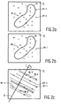
- Figures 2a, 2b and 2c illustrate a sample to be studied by means of a tilt series.
- the sample 2 consists of an object 14, and is provided with gold particles as markers. These markers may be identified by applying a first (rough) selection method known per se. However, as a result of this first rough recognition step many candidate markers that are not real markers may be identified as true markers (false positive candidates).
- the first set of markers so obtained is represented in Figure 2a by references 8-1, 8-2, ... in general 8-i.
- a following selection step is made; in this latter step one or two probability parameters are attributed to each candidate marker in each image, and a second set is selected as a subset of candidate markers from the first set of candidate markers on the basis of said probability parameters.
- FIG. 2b The result of this selection step is represented in Figure 2b , in which some markers of the first set considered to be false positive candidates are indicated by dashes 18-i, and the markers of the first set that are selected as true markers (the second set of markers) are indicated by crosses 16-i.
- Figure 2c the result of the projection of the true markers 16-i onto a single image plane 2 is illustrated.
- markers 16-i rotate about the tilt axis 6.
- each marker will produce a rectilinear trace 20-i in said image plane, but some markers are positioned in such a way that their traces coincide, see, for example, marker pairs 16-1, 16-2 and 16-3, 16-4.
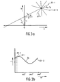
- the straight lines obtained in this way are detected by means of an algorithm comprising the Hough transformation, as will be described with reference to Figures 3a and 3b .
- a straight line 22-1 is represented in a usual system of (x,y) axes.
- a point of this line is denoted as x 0 , y 0 .
- a bundle of straight lines all going through point x 0 , y 0 is denoted in general as 22-i.
- So line 22-1 having one particular value of r and of ⁇ , is represented by one point 22-1 in Figure 3b .
- all other lines going through point x 0 , y 0 in Figure 3a are represented by a point in Figure 3b , all lines 22-i in Figure 3a providing points 22-i in Figure 3b , and all points 22-i together constituting a sine-shaped line 24.
- a bundle of lines all going through another point x 1 , y 1 in Figure 3a will give rise to another sine-shaped line in Figure 3b ; if these two sine curves intersect, it means that the two points x 0 , y 0 and x 1 , y 1 are situated on the same line in Figure 3a , which is always true for two points.
- Finding points that are all situated on the same line means ⁇ in terms of the Hough representation of Figure 3b ⁇ that one should look for intersection points of all sine curves corresponding to those points. If these sine curves all have the same intersection point, it means that all points x i , y i are situated on the same line in Figure 3a .
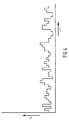
- the quantity S is, as is generally known, a measure of the divergence of the distribution of the numbers of markers over the various values of r; in other words S is a measure of the "peakiness" of the histogram.
- S is a measure of the "peakiness" of the histogram.
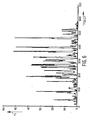
- Figure 6 shows the histogram corresponding to the extremal value of S referred to above, i.e. the line direction perpendicular to the tilt axis. Comparing the histogram according to Figure 6 with the histogram of Figure 4 it is clear that the first histogram is much more "peaky", and thus has a very high probability of being the one that corresponds to the direction perpendicular to the tilt axis. From Figure 6 one may identify the various parallel lines of markers as schematically depicted in Figure 1b , 2c or 5a .
Landscapes
- Engineering & Computer Science (AREA)
- Physics & Mathematics (AREA)
- Life Sciences & Earth Sciences (AREA)
- Biomedical Technology (AREA)
- General Health & Medical Sciences (AREA)
- Molecular Biology (AREA)
- Health & Medical Sciences (AREA)
- General Physics & Mathematics (AREA)
- Multimedia (AREA)
- Theoretical Computer Science (AREA)
- Chemical & Material Sciences (AREA)
- Analytical Chemistry (AREA)
- Image Analysis (AREA)
- Image Processing (AREA)
Claims (6)
- Verfahren zur automatischen Ausrichtung von Kippserien (2-i) in einem Elektronenmikroskop mit:- Auftragen von Markern (8-i) auf eine durch das Elektronenmikroskop abzubildende Probe (2);- Bereitstellen einer Kippserie von Bildern (2-i) der Probe;- Identifizieren eines ersten Satzes von Kandidatenmarkern (8-i) in jedem der Bilder in der Kippserie;- Attributieren jedes Kandidatenmarkers in jedem Bild mit mindestens einem Wahrscheinlichkeitsparameter;dadurch gekennzeichnet, daß das Verfahren ferner aufweist:- Auswählen eines zweiten Satzes (16-i) als Teilsatz von Kandidatenmarkern aus dem ersten Satz von Kandidatenmarkern auf der Grundlage des mindestens einen Wahrscheinlichkeitsparameters;- Projizieren der Kandidatenmarker im zweiten Satz auf ein einziges Bild;- Anwenden eines Anpaßalgorithmus, um einen Satz paralleler Geraden oder sehr langer Ellipsen (20-i) zu bestimmen, die an die Kandidatenmarker im einzigen Bild am besten angepaßt sind;- Ausrichten der Bilder in der Kippserie auf der Grundlage der identifizierten Kandidatenmarker.
- Verfahren nach Anspruch 1, wobei der Anpaßalgorithmus, der zum Bestimmen des Satzes paralleler Geraden verwendet wird, die Hough-Transformation aufweist.
- Verfahren nach Anspruch 1, wobei der Anpaßalgorithmus, der zum Bestimmen des Satzes paralleler Geraden oder zum Bestimmen eines Satzes sehr langer Ellipsen verwendet wird, durch die generalisierte Hough-Transformation gebildet ist.
- Verfahren nach Anspruch 1, wobei vor Identifizieren von Kandidatenmarkern in jedem der Bilder in der Kippserie ein Kreuzkorrelationsverfahren auf die Bilder der Kippserie angewendet wird.
- Verfahren nach einem der vorstehenden Ansprüche, wobei der Wahrscheinlichkeitsparameter aus mindestens einer der folgenden Größen abgeleitet wird: Größe des Markers und lokaler Kontrast des Markers.
- Verfahren nach Anspruch 2, wobei der Anpaßalgorithmus ferner aufweist:- Ableiten einer sinusförmigen Kurve (24) für jeden Kandidatenmarker auf der Grundlage der Koordinaten des entsprechenden Kandidatenmarkers gemäß der Hough-Transformation;- Ableiten einer Anzahl von Histogrammen (Fig. 4) aus den sinusförmigen Kurven, die für jede Richtung (α) die Beziehung zwischen der Dichte von Kandidatenmarkern und dem Linienabstandsparameter (r) angeben, gemäß der Hough-Transformation;- Anwenden einer Entropie- (S) Operation auf jedes der Histogramme, die zu einem Satz von Entropieparametern (Si) mit einem Entropieparameter für jedes Histogramm führt;- Ermitteln des Minimalwerts im Satz von Entropieparametern;- Identifizieren des Histogramms, das dem Minimalwert entspricht, als jenes, das den höchsten Peak-Diversitätsgrad zeigt;- Auswählen einer Anzahl von Peaks aus dem letztgenannten Histogramm;- Ableiten des entsprechenden Linienabstandsparameters aus jeder Peakposition im Histogramm gemäß der Hough-Transformation.
Priority Applications (4)
| Application Number | Priority Date | Filing Date | Title |
|---|---|---|---|
| JP2003411944A JP4451647B2 (ja) | 2002-12-11 | 2003-12-10 | 電子顕微鏡におけるチルト系列の自動配置決定方法 |
| US10/733,741 US7463791B2 (en) | 2002-12-11 | 2003-12-11 | Method for automatic alignment of tilt series in an electron microscope |
| DE60322399T DE60322399D1 (de) | 2003-12-13 | 2003-12-13 | Verfahren zum automatischen Ausrichten einer Serie von relativ zueinander gekippten Bildern in einem Elektronmikroskop |
| EP03028796A EP1542259B1 (de) | 2002-12-11 | 2003-12-13 | Verfahren zum automatischen Ausrichten einer Serie von relativ zueinander gekippten Bildern in einem Elektronmikroskop |
Applications Claiming Priority (2)
| Application Number | Priority Date | Filing Date | Title |
|---|---|---|---|
| EP02080689 | 2002-12-11 | ||
| EP03028796A EP1542259B1 (de) | 2002-12-11 | 2003-12-13 | Verfahren zum automatischen Ausrichten einer Serie von relativ zueinander gekippten Bildern in einem Elektronmikroskop |
Publications (2)
| Publication Number | Publication Date |
|---|---|
| EP1542259A1 EP1542259A1 (de) | 2005-06-15 |
| EP1542259B1 true EP1542259B1 (de) | 2008-07-23 |
Family
ID=34796677
Family Applications (1)
| Application Number | Title | Priority Date | Filing Date |
|---|---|---|---|
| EP03028796A Expired - Lifetime EP1542259B1 (de) | 2002-12-11 | 2003-12-13 | Verfahren zum automatischen Ausrichten einer Serie von relativ zueinander gekippten Bildern in einem Elektronmikroskop |
Country Status (3)
| Country | Link |
|---|---|
| US (1) | US7463791B2 (de) |
| EP (1) | EP1542259B1 (de) |
| JP (1) | JP4451647B2 (de) |
Families Citing this family (9)
| Publication number | Priority date | Publication date | Assignee | Title |
|---|---|---|---|---|
| EP1801593A1 (de) * | 2005-12-22 | 2007-06-27 | Koninklijke Philips Electronics N.V. | Abbildungsmethode von biologischen Proben unter Verwendung von inorganischen Nanopartikeln als Markierungsagentien |
| EP1890136A1 (de) * | 2006-08-16 | 2008-02-20 | FEI Company | Verfahren zum Erhalt von Bilderen für Abschnitte einer Probe |
| US20090060348A1 (en) * | 2007-08-28 | 2009-03-05 | Donald Martin Monro | Determination of Image Similarity |
| KR100902403B1 (ko) | 2007-09-11 | 2009-06-11 | 한국기초과학지원연구원 | 투과전자현미경 3차원 관찰 전용 문 그리드 및 그 제조방법 |
| JP5555653B2 (ja) * | 2011-03-29 | 2014-07-23 | 日本電子株式会社 | 電子顕微鏡および3次元像構築方法 |
| US9064170B2 (en) * | 2012-01-11 | 2015-06-23 | Nokia Technologies Oy | Method, apparatus and computer program product for estimating image parameters |
| US8605972B2 (en) | 2012-03-02 | 2013-12-10 | Sony Corporation | Automatic image alignment |
| US8912488B2 (en) * | 2012-11-15 | 2014-12-16 | Fei Company | Automated sample orientation |
| CN113808190B (zh) * | 2021-09-23 | 2023-07-28 | 西南石油大学 | 一种基于电成像测井图像的页岩纹层信息定量提取方法 |
Family Cites Families (1)
| Publication number | Priority date | Publication date | Assignee | Title |
|---|---|---|---|---|
| CA2446853A1 (en) * | 2001-05-15 | 2002-11-21 | Psychogenics Inc. | Systems and methods for monitoring behavior informatics |
-
2003
- 2003-12-10 JP JP2003411944A patent/JP4451647B2/ja not_active Expired - Lifetime
- 2003-12-11 US US10/733,741 patent/US7463791B2/en not_active Expired - Lifetime
- 2003-12-13 EP EP03028796A patent/EP1542259B1/de not_active Expired - Lifetime
Also Published As
| Publication number | Publication date |
|---|---|
| US7463791B2 (en) | 2008-12-09 |
| JP4451647B2 (ja) | 2010-04-14 |
| JP2004193128A (ja) | 2004-07-08 |
| US20040119016A1 (en) | 2004-06-24 |
| EP1542259A1 (de) | 2005-06-15 |
Similar Documents
| Publication | Publication Date | Title |
|---|---|---|
| Moberg et al. | Distance maps to estimate cell volume from two‐dimensional plankton images | |
| Gubins et al. | SHREC 2020: Classification in cryo-electron tomograms | |
| Emerson et al. | Individual fibre segmentation from 3D X-ray computed tomography for characterising the fibre orientation in unidirectional composite materials | |
| Xu et al. | High-throughput subtomogram alignment and classification by Fourier space constrained fast volumetric matching | |
| Brandt et al. | Automatic alignment of transmission electron microscope tilt series without fiducial markers | |
| EP0641020A2 (de) | Mehrfachabtastungsmethode für eine Partikelanalyse auf halbleitenden Scheiben | |
| US20060226359A1 (en) | Method and apparatus for quantitative three-dimensional reconstruction in scanning electron microscopy | |
| EP3611695A1 (de) | Erzeugung von anmerkungsdaten von gewebebildern | |
| EP1542259B1 (de) | Verfahren zum automatischen Ausrichten einer Serie von relativ zueinander gekippten Bildern in einem Elektronmikroskop | |
| Alpers et al. | Geometric reconstruction methods for electron tomography | |
| Krieger Lassen | The relative precision of crystal orientations measured from electron backscattering patterns | |
| CN118429440A (zh) | 一种并行共焦系统的针孔标定方法 | |
| Lukashchuk | Method of automatic identification of ruler scales on images to solve the problem of estimating the geometric dimensions of certain objects | |
| Ueda et al. | 3D shape estimation of wires from 3D x-ray CT images of electrical cables | |
| CN118465816A (zh) | X射线源焦点测试方法、测试卡、装置、设备和存储介质 | |
| Bock et al. | Efficient and robust image registration for two-dimensional micro-X-ray fluorescence measurements | |
| Gremillet et al. | Dedicated image analysis techniques for three-dimensional reconstruction from serial sections in electron microscopy | |
| Moore | Recent progress in automatic image analysis | |
| Xu et al. | Validation and reliability of the 3D calibration evaluation algorithm for SPM | |
| CN118536881B (zh) | 一种工程建设施工质量动态评估方法、系统及存储介质 | |
| CN115909307B (zh) | 一种基于语义分割的指针式仪表自动读数方法 | |
| US12456600B2 (en) | Scanning electron microscopy-based tomography of specimens | |
| JP2004212277A (ja) | パターンを検査するための方法 | |
| Shirazi et al. | Nonlinear stereology: Estimation of morphological features of anisotropic ellipsoids with various spatial distributions | |
| Küçükyilmaz et al. | Investigation of Geometric Invariance Properties of Hu Moments for Image Processing Applications |
Legal Events
| Date | Code | Title | Description |
|---|---|---|---|
| PUAI | Public reference made under article 153(3) epc to a published international application that has entered the european phase |
Free format text: ORIGINAL CODE: 0009012 |
|
| 17P | Request for examination filed |
Effective date: 20031213 |
|
| AK | Designated contracting states |
Kind code of ref document: A1 Designated state(s): AT BE BG CH CY CZ DE DK EE ES FI FR GB GR HU IE IT LI LU MC NL PT RO SE SI SK TR |
|
| AX | Request for extension of the european patent |
Extension state: AL LT LV MK |
|
| AKX | Designation fees paid |
Designated state(s): DE FR GB NL |
|
| GRAP | Despatch of communication of intention to grant a patent |
Free format text: ORIGINAL CODE: EPIDOSNIGR1 |
|
| GRAS | Grant fee paid |
Free format text: ORIGINAL CODE: EPIDOSNIGR3 |
|
| GRAA | (expected) grant |
Free format text: ORIGINAL CODE: 0009210 |
|
| AK | Designated contracting states |
Kind code of ref document: B1 Designated state(s): DE FR GB NL |
|
| REG | Reference to a national code |
Ref country code: GB Ref legal event code: FG4D |
|
| REF | Corresponds to: |
Ref document number: 60322399 Country of ref document: DE Date of ref document: 20080904 Kind code of ref document: P |
|
| NLV1 | Nl: lapsed or annulled due to failure to fulfill the requirements of art. 29p and 29m of the patents act | ||
| PG25 | Lapsed in a contracting state [announced via postgrant information from national office to epo] |
Ref country code: NL Free format text: LAPSE BECAUSE OF FAILURE TO SUBMIT A TRANSLATION OF THE DESCRIPTION OR TO PAY THE FEE WITHIN THE PRESCRIBED TIME-LIMIT Effective date: 20080723 |
|
| PLBE | No opposition filed within time limit |
Free format text: ORIGINAL CODE: 0009261 |
|
| STAA | Information on the status of an ep patent application or granted ep patent |
Free format text: STATUS: NO OPPOSITION FILED WITHIN TIME LIMIT |
|
| 26N | No opposition filed |
Effective date: 20090424 |
|
| REG | Reference to a national code |
Ref country code: FR Ref legal event code: PLFP Year of fee payment: 13 |
|
| REG | Reference to a national code |
Ref country code: FR Ref legal event code: PLFP Year of fee payment: 14 |
|
| REG | Reference to a national code |
Ref country code: FR Ref legal event code: PLFP Year of fee payment: 15 |
|
| PGFP | Annual fee paid to national office [announced via postgrant information from national office to epo] |
Ref country code: GB Payment date: 20221219 Year of fee payment: 20 Ref country code: FR Payment date: 20221222 Year of fee payment: 20 Ref country code: DE Payment date: 20221130 Year of fee payment: 20 |
|
| REG | Reference to a national code |
Ref country code: DE Ref legal event code: R071 Ref document number: 60322399 Country of ref document: DE |
|
| REG | Reference to a national code |
Ref country code: GB Ref legal event code: PE20 Expiry date: 20231212 |
|
| PG25 | Lapsed in a contracting state [announced via postgrant information from national office to epo] |
Ref country code: GB Free format text: LAPSE BECAUSE OF EXPIRATION OF PROTECTION Effective date: 20231212 |
|
| PG25 | Lapsed in a contracting state [announced via postgrant information from national office to epo] |
Ref country code: GB Free format text: LAPSE BECAUSE OF EXPIRATION OF PROTECTION Effective date: 20231212 |